1
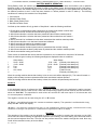
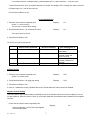
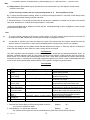
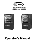
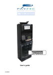
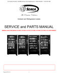
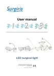
To Purchase This Item, Visit BMI Gaming | www.bmigaming.com | 1-800-746-2255 | + 1-561-391-7200 SL5000 Operator’s Manual Rev. 2012.02.27 1 To Purchase This Item, Visit BMI Gaming | www.bmigaming.com | 1-800-746-2255 | + 1-561-391-7200 INTRODUCTION Congratulations on the purchase of your new SL5000. This SL5000 has been designed to give you many years of dependable service. It requires little maintenance and is easy to set up and operate. READ THIS MANUAL COMPLETELY Your SL5000 is designed to operate simply and reliably, but to take full advantage of your vendor, please read this owner’s manual thoroughly. It contains important information regarding installation and operations, as well as a brief trouble-shooting guide. EQUIPMENT INSPECTION After you have received your machine and have it out of the box, place it on a secure surface for further inspection. Note: Any damages that may have occurred during shipping must be reported to the delivery carrier immediately. Reporting damages and the seeking of restitution is the responsibility of the equipment owner. The factory is willing to assist you in this process in any way possible. Feel free to contact our Customer Care Department with questions you may have on this process. It is important that you keep the original packaging for your vending machine at least through the warranty period. If your machine needs to be returned for repair, you may have to purchase this packaging if it is not retained. Once your have your vendor located, we suggest that you keep this manual for future reference, or you can view this manual online at www.seagamfg.com. Should any problems occur, refer to the section entitled “COMMON QUESTIONS AND ANSWERS”. It is designed to help you quickly identify a problem and correct it. For Service and Customer Care: 9:00 a.m. - 5:30 p.m. Mon thru Fri +44(0)1492 874010 +44(0)1492 874644 Fax email: [email protected] For Service and Customer Care: 8:30 a.m. - 4:00 p.m. CST. Mon thru Fri 815.297.9500 ext 160 815.297.1758 Fax email: [email protected] Seaga UK Ltd. Unit 8, Caebach, Off Builders Street Llandudno North Wales LL30 1DR seaga.co.uk Seaga Manufacturing, Inc. 700 Seaga Drive Freeport, IL 61032 U.S.A. seagamfg.com IMPORTANT NOTICES Your vendor (s) are intended for indoor use only Your vendor (s) must be set on a level, well-supported location. Always unload vendor before transporting it. Do not load your vendor with disfigured or damaged product. Rev. 2012.02.27 2 To Purchase This Item, Visit BMI Gaming | www.bmigaming.com | 1-800-746-2255 | + 1-561-391-7200 Section 1 Brief Description of your SL5000 Locks LCD Display Selection Pads Coin Validator Vend Area Fig.1 Coils Coin Box HOW TO LOCK & UNLOCK THE DOOR OF VENDOR Your SL5000 has 2 locks. To open the door, unlock the top and bottom locks by turning the keys clockwise. ELECTRICAL CONNECTION The SL5000 may be driven by a 12-volt battery or via a permanent 12 VDC supply obtained through an AC/DC adapter. The SL5000 incorporates a Multi Functional Controller Board with a range of features such as 5 individual selections and multiple coin handling in a compact size. PRODUCT SELECTION PRICING AND LABELS Product selection is made using the 5 selection pads (see photo above). The prices can be set by entering the Service Mode. DELIVERY SYSTEM The delivery system of your SL5000 incorporates a Selection Pad, an LCD Display and helix coils. The customer inserts money into the coin slot and enters their selection on the Selection Pad; the selected Driver Motor turns the helix coil and vends the product. KEYPAD AND LCD DISPLAY The Selection Pad has touch-sensitive operation. Light pressure will be necessary to activate the appropriate motor/helix coil relating to any particular shelf. The Selection Pad is used by the customer to make their selection, and by the operator to set and test the many functions of the vendor (Fig.1). The LCD Display shows the customer the amount of money entered into the vendor and the cost of their selection, it shows the operator the Service Mode function for setting and testing the various functions of the vendor. Rev. 2012.02.27 3 To Purchase This Item, Visit BMI Gaming | www.bmigaming.com | 1-800-746-2255 | + 1-561-391-7200 BATTERY MODE OF OPERATION During Battery mode, the machine operates in ‘Sleep Mode’. This means that when the machine is not in operation (between vends), it will automatically shut down in order to save battery power, thus prolonging the life of the battery. During ‘Sleep Mode’ the machine display turns off its left hand digit (unless there is a value greater than 0 present) and the machine monitors to see if a coin has been inserted or a button pressed in order to ‘wake-up’. The following conditions will ‘wake-up’ the machine from ‘Sleep Mode’. 1. Coin Insertion 2. Selection Button Press 3. Black (Reset) Button Press 4. Red Service Button Press On Wake-up the machine will only go back to ‘Sleep Mode ‘ under the following conditions: 1. Directly after a vend has been made (Unless there is excess credit present in which case the machine will wait a further 60 seconds before going to sleep]. 2. After 30 seconds after a selection has been pressed and the machine contains product. 3. After 20 seconds after a selection has been pressed and the machine does not contain a product. 4. After 5 seconds if an invalidated coin has been inserted and the machine contains product. 5. After 60 seconds after a coin has been inserted and validated. 6. After 5 seconds if the machine is completely empty. 7. After 5 seconds after if the machine is out of order. 8. After 5 seconds after the black (reset) button is pressed and the machine is empty. 9. After 20 seconds after the black (reset) button is pressed and the machine contains product. 10. After 8 seconds after leaving service mode These values are extended each time a selection is pressed or coin is inserted to a maximum of 60 seconds. When the machine goes to sleep, the following messages are displayed under set conditions i. ii. iii. iv. v. vi. When Awake 00.00 – 09.00 10.00 – 99.99 Free Test Out of Ordr - - .- - When Asleep 0.00 – 9.99 (Decimal points always on) 10.00 – 99.99 (Decimal points always on) Fr.ee (Decimal points always on) Te.st (Decimal points always on) F-Er (Fatal Error set) -.- (Decimal point always on) When the vending machine detects that a battery is low an error code will be displayed (51). This code will remain on display until the battery has been replaced and the black reset button has been pressed. When the vending machine detects that a battery is dead, the machine will permanently turn itself off. Section 2 SERVICE MODE In this dedicated version of software the VMC is limited to 5 columns, each with a dedicated “negative counters” to count down the stock in each column. When the corresponding negative counter reaches zero the selection is shown as “Sold Out”. The capacities for each column are set with the “nC“ menu option. If all columns are sold out coin acceptance is inhibited. The negative counters can be reset using the “A” or “B” buttons: “A” Button – unconditionally resets ALL counters to maximum capacity. The operation is confirmed with a long bleep and ALL r-ld on the display. “B” Button – only resets any counters that are zero (i.e. fully vended)to their maximum capacity. Counters that are not fully vended are not changed. The operation is confirmed with a long bleep and r-ld on the display. Operation The operation of the machine can be adjusted by entering service mode by pressing the red button on the VMC circuit board and then accessing the appropriate operation. Price setting, coin value setting, and vend-credit criteria can be read and adjusted from here. The user can also perform tests on the machine through this mode. Note: any Credit will be cancelled on entry to Service Mode. Rev. 2012.02.27 4 To Purchase This Item, Visit BMI Gaming | www.bmigaming.com | 1-800-746-2255 | + 1-561-391-7200 1. Enter Service Mode by pressing the Service Button on the VMC Circuit board. On entry to Service Mode, up to 8 Error Codes may be displayed. These can be cleared using the Clear Errors menu option. Error Code Display Er.** where ** is the error number 2. Each Service Code can then be accessed by repeat pressing of the Service Button Pressing Service Button (AUDIT) Displays Au.-- Pressing Service Button (PRICE SETTING) Displays PS.-- Pressing Service Button (COIN VALUE SETTING) Displays Cn.-- Pressing Service Button (CONTROL WORD SETTING) Pressing Service Button (TEST MODE) Displays Ct.** Where ** is the current word Displays So.0* Where * is the current state (0 or 1) Displays St.0* Where * is the current state (0 or 1) OR Displays tE.-- Pressing Service Button (TEST ALL MOTORS) Displays AL.-- Pressing Service Button (CLEAR ERRORS) Displays CL.-- Pressing Service Button (FACTORY RESET) Displays Fr.-- Pressing Service Button (EXIT) Machine goes to Sleep Pressing Service Button (SOUND On/Off) Pressing Service Button (STOCK MODE On/Off) OR SL5000 – (NEGATIVE COUNTERS) 3. Service Mode can be exited by stepping through all the menu options using the Service Button, or automatically if there is no activity for 30 seconds. On Exit the software version number is displayed as u2.10 Audit Within Service Code AU (Audit) readings can be taken from the Display with regards to cash taken, and number of products vended. The following details can be obtained on the Display. 1 2 3 4 Total Cash Taken (up to 9999.99) Total Product Vended (up to 9999) Individual Product Vended (from each selection) up to 999 Total Cash Out as change (up to 9999.99) # Press the Red Service Button repeatedly till the LCD Displays Au. You are now in Audit Mode Press Selection 1 to reveal the total cash ($) and (c) taken. Displays 88.88 for 0.75 seconds before showing the cash values: Displays ****and--. ** Press Selection 2 to reveal the total product vended Displays **** Press Selection 3 to reveal the individual product vended The display scrolls through each selection displaying the quantity vended 1.*** to 9.***, then A.*** through to F.*** and then 0.*** for selections 1 to 16 respectively. Press any selection key to end this sequence immediately. Returns to Au- at end of routine. Press Selection 4 to clear all the Audit data Rev. 2012.02.27 Displays Clr 5 To Purchase This Item, Visit BMI Gaming | www.bmigaming.com | 1-800-746-2255 | + 1-561-391-7200 Press Selection 5 to : show the total cash OUT($) and (c) # Displays ****and--. ** then negative counter values (selection n, count xx) Displays 0n.xx then the “no load” battery voltage Displays **.*0 then the “under load” battery voltage Displays **.*0 Press Service Button to scroll to exit. Price Setting Price Setting can be done by entering Service Code PS. Each selection can be allocated any price from 00.00 to 99.99, and is achieved by inserting coins to the vend amount and allocating that amount to the desired selection(s). 1 Press the Red Service Button repeatedly until the LCD You are now in Price Setting Mode Displays PS.— 2 Insert coins to the first desired price (for simplicity set the lowest price first) Credit will accumulate on the display. Displays **. ** 3 Press desired selection button to store displayed credit to that selection – a long bleep and a “Set” display will confirm that the price has been programmed. 4 Insert additional coins if required and repeat for other selections. 5 Press Service Button to scroll to exit. Prices may be set from 00.00 to 99.99 (depending upon coin values). The default price setting is 1.00 Coin Value Setting Coin Value setting allows for the changing of the individual values for the 6 coin outputs from the Coin Acceptor. Values can be adjusted from 00.00 to 99.99 or can be set as a free vend token. 1.Press the Red Service button repeatedly until Displays Cn.-- Displays 00.** Displays 00.** 4. Press Selection Button 3 to increment the **.- Value Displays **.?? 5. Press Selection Button 4 to decrement the **.-Value Displays **.?? 6. Press Selection Button 5 to set the coin as a Free vend Displays Token (pressing any other key reverts to a value) FrEE You are now in the Coin Value setting Mode You first need to set the value for the coin 2. Press Selection Button 1 to increment the --.** Value 3. Press Selection Button 2 to decrement the --.** Value That is the cent/pence value set, now we need the dollar/euro/pound value Now with the value on the display, insert the coin for which the value must be assigned Rev. 2012.02.27 6 To Purchase This Item, Visit BMI Gaming | www.bmigaming.com | 1-800-746-2255 | + 1-561-391-7200 7. Insert Required Coin until it is accepted and the unit “bleeps” and displays “Set” to assign the value to that coin 8. Repeat steps 3 to 7 until all coins are set. 9. Press Service Button to exit Control Word Setting 1. Press the service button repeatedly until (where ** is current value) You are now in Control Word Setting Displays Ct. ** 2. Press Selection Button 1 to increment the value Displays Ct.** The control word is now set 4. Press Service Button to exit The control word options supported are: Code 03 Credit vs. Vend Price Before vend is performed Credit >= Vend Price Excess Credit (G13 Coin Acceptor) Cancelled immediately 04 Credit >= Vend Price Held until power removed 05 Credit >= Vend Price Held for 60 seconds 06 None – Free Vend Mode Not applicable Excess Credit (Coin Changegiver) # Given as change immediately Returned when ER pressed or held until power removed Returned when ER pressed or held for 60 seconds Not applicable SOUND (On/Off) 1. Press the service button repeatedly until (where * is current value) Displays So.0* 2. Press Selection Button 1 to toggle the setting Displays So.0* 3. Press Service Button to exit A value of 1 enables the sound, 0 disables the sound. Sounds within the menus cannot be disabled. Negative Counter Setting This menu option, only available within the SL5000 version of the software allows the maximum capacity to be set for each selection. When the stock is “filled” (A or B button) these are the numbers that are loaded into the negative counters. 1.Press the Red Service button repeatedly until Displays Press any selection : You are now in the Negative Counter setting Mode Rev. 2012.02.27 7 nC.-- To Purchase This Item, Visit BMI Gaming | www.bmigaming.com | 1-800-746-2255 | + 1-561-391-7200 2. Press Selection Button 1 to increment the 0s.--. Value (the selection number, 01 – 05, nn is the current negative counter capacity for this selection) 3. Press Selection Button 2 to decrement the 0s.--. Value (the selection number, 1 – 5, nn is the current negative counter capacity for this selection) 4. Press Selection Button 3 to increment the counter capacity nn (maximum value 40) 5. Press Selection Button 4 to decrement the counter capacity nn Displays 0s.nn Displays 0s.nn Displays 0s.nn Displays 0s.nn 6. Press the Red Service Button to exit the mode TEST MODE 1. Press the service button repeatedly until Displays tE.- - 2. Press Service Button to exit In Test Mode, pressing a selection switch will operate the selected motor. If a coin is inserted its value will be displayed for 1 second. ALL MOTORS MODE 1. Press the service button repeatedly until Displays AL.- - 2. Press Service Button to exit In this mode, press selection button 1 to commence a single test vend on all fitted motors. CLEAR ERRORS 1. Press the service button repeatedly until Displays CL.- - 2. Press Service Button to exit In this mode, press any selection button to clear all errors – confirmed with a “CLr” display. FACTORY RESET OF SETTINGS 1. Press the service button repeatedly until Displays Fr.- - 2. Press Service Button to exit In this mode, press selection button 2 for two seconds to reset to these factory default settings (confirmed with a “Set” display). Rev. 2012.02.27 8 To Purchase This Item, Visit BMI Gaming | www.bmigaming.com | 1-800-746-2255 | + 1-561-391-7200 Prices ; Depends on software version Coin Values: 0.05, 0.10, 0.20, 0.50, 1.00, 2.00 Control Word: 05 Sound: ON Stock Mode: OFF Payment Devices: 00 (Changegiver and Bill Reader disabled) Negative Counters All 12 Error Codes Error Code Number 01 .. 16 Fault detected Action Hard/Soft fault Soft 20 EEPROM Checksum Error Hard 30 Coin Mech fault Hard Repair/replace motor/home switch Factory Reset through the menus to clear the fault, then set up prices etc again Repair/replace Coin Mech Keypad fault (key 1..16 respectively) Hard Repair/replace keypad Battery Low – no load voltage too low Battery Low – under load voltage too low Battery Low – battery internal resistance too high Battery nearly low Hard* Replace/recharge the battery Hard* Replace/recharge the battery Hard* Replace the battery 41 – 57 70 71 72 73 Motor 01..16 respectively Warning Replace/recharge the battery soon Soft Errors – unit will continue to operate though failed motors will show as “Sold Out” and be blocked from operation if selected. If the unit has detected 8 different soft faults it will become a Hard fault. Hard Errors – the unit is put out of service. This mode can only be cleared via the service button. Hard* Errors – the unit is put out of service until the battery is replaced/recharged and the service button is pressed to clear the error conditions. MOTOR ASSIGNMENT The following details would be helpful in a proper assignment of the Motor version. The SL5000 uses Seaga 3 wire 12v DC gray motor. Motor Version Map Version Name Description 1 2 3 4 5 6 Spiral Motor Spiral Motor Reserved Reserved Reserved Reserved Seaga 3 Wire Motor 24V white Seaga 3 Wire Motor 12V grey Start Sense Open Open Operation How to Set up your Motor Version: Rev. 2012.02.27 9 Home Time-out Assignment Indicator Yes Yes ** ** Individual Individual ------- To Purchase This Item, Visit BMI Gaming | www.bmigaming.com | 1-800-746-2255 | + 1-561-391-7200 To Change .. do the following: 1. Press the Red Service Button till AS where * is the current version # 2. Press Button 1 (or 2) to increment/decrement Version # 3. Press Button 3 to store Version Value 4. Press Red Service Button or Reject to scroll to exit Displays AS-* Displays AS.0? where ? is version 1 to 6 Displays set Displays 00.00 Notes - When setting up a Motor Version a default Timing value will be assigned automatically, (see default value). This may need to be changed (see timing value setting). The default motor version is Version 2. The VMC will return to Normal Mode (00.00) 60 seconds after the last button has been pressed unless the Red Service Button has been pressed or the reject is pressed. Timing Value The timing value is a measure of time that allows the VMC to either ignore any signals from the motor until the time has expired, or if the time has expired without any signals. Depending on the Version, the timing Value has different characteristics. Generally speaking the timing value is set to the normal vend time. For example, if the vend normally takes 6 seconds to complete, then set the timing value to 6. This allows for the VMC to ‘expect’ a home signal at the required time and to ignore any spurious signals in the meantime. It also sets an appropriate delay after a ‘home’ should be expected, disabling power to the motor if this home wasn’t reached. In this case the motor is inhibited, the appropriate error code is set and the money entered is returned to the user. The Vend cycle is Voltage and Load dependent so an approximate setting of the timing value needs to be set. The vend cycle, is the time from motor start (when at home) to motor end (return to Home) in seconds. This translates directly to the timing value that re-conditions the value for correct operation. Operation 1. Press the Red Service Button to scroll to 2. Press Button 1 (or 2) to increment/decrement Value 3. Press Button 4 to store Timing Value Displays AS.— Displays AS.** where ** is value 01 to 99 Displays set Notes - The current timing value is displayed whilst doing a test as Pl.**, where ** is current value The timing Value can be set from 00 to 99. For Version 1 Motors the default timing value is 7 For Version 2 Motors the default timing value is 7 The timing value reverts back to default every time a version change is set The timing value cannot be individually assigned and applies to all outputs when set. The VMC will return to Normal Mode (00.00) 60 seconds after the last button has been pressed unless the Red Service Button has been pressed or the reject is pressed. Negative Counter Sold Out Feature Negative Counter can only be set and calibrated for each selection by entering Service Code nc . Selection can be incremented or decremented from 1 to 5 using buttons 1 and 2 respectively and each shelf can be allocated a negative counter from --.00 to --.99, where - - belongs to the shelf number. Negative counter value is incremented by button 3 and decremented by button 4. Each configuration can be saved by button no. 5. 1.Operation 1. Press the Red Service Button Repetitively till LCD Displays:- nC .- You are now in Negative Counter Setting Mode. 2.Press Selection Button 1 to increment the **.- - Value i.e shelf selection no (** no. of shelf). The LCD will now display the incremented selection no. Rev. 2012.02.27 10 To Purchase This Item, Visit BMI Gaming | www.bmigaming.com | 1-800-746-2255 | + 1-561-391-7200 3.Press Selection Button 2 to decrement the **.- - Value i.e shelf selection no (** no. of shelf). The LCD will now display the decremented shelf selection no. The Shelf for which the Negative Counter has to be set has now been decided ; We now need to set the value of the Negative Counter for the selected shelf. 4. Press Selection Button 3 to increment the - - .** Value i.e negative counter value (** negative counter setting). 5. Press Selection Button 4 to decrement the - - .** Value i.e negative counter value (** negative counter setting). Press button 5 to store the decided negative counter value assigned to the selected shelf. The Display will show C.set 6. Repeat steps 2 to 5 till all the shelves have been assigned the desired negative counter value. 7.Press Reject Button to exit Note: Default values of all Negative Counters are factory set as per the No. of spaces in each coil. If the user changes a coil to one which has different number of spaces then the Negative Counter pertaining to that coil will have to be reprogrammed as per procedure mentioned earlier. 2. Negative Counter Display : To see the current status of all the Negative Counters assigned to different shelves , enter the service Audit mode. ( Au- - ). In the Audit mode Press button 5 , the Negative Counter value along with the selection no ( **.- - where ** represents the shelf that has been selected and the - - represents the current value of the Negative Counter that has been assigned to that shelf.) is displayed in scrolling mode from shelf 1 to 5. 3. Sold out Feature: After setting the Negative Counter for each selection, the Negative Counter will get decremented by 1 each time that a valid vend is made. Negative Counters for each shelf thus keep on decrementing as and when a vend is made, from the set value to zero. When the value of any Negative Counter reaches zero, pressing the selection button assigned to that Negative Counter will then prompt the display to show SOLD OUT. No vend can then be made from that shelf. Vends from other shelves will not be interrupted and can be made as normal Note: If a coil has 7 spaces/products, it will show SOLD OUT after vending 7 products. 4. Resetting of Negative Counters of fully vended shelves: Button no. B (fig.2) has been assigned for the resetting of the Negative Counter of fully vended shelves. If one or more selection(s) is /are sold out, then keeping the button B pressed for 3-4 seconds will reset all the Negative Counters of the shelves which were fully sold out at that moment. Button A & B Fig.2 A long beep with r-ld will appear on the display indicating that partial resetting has taken place and that the Negative Counters which were zero prior to resetting have been restored to set value. The Negative Counters of all other selections which were not fully sold out at that moment will not be disturbed and will maintain the value they had reached. Rev. 2012.02.27 11 To Purchase This Item, Visit BMI Gaming | www.bmigaming.com | 1-800-746-2255 | + 1-561-391-7200 Note: a). Safety Feature : Button B will only be operational from the moment that any of the Negative Counters have reached to zero value. If none of the neg. counters are zero, then pressing button no. B will not yield any results. b). To prevent accidental partial resetting, button no. B needs to be kept pressed for 3-4 seconds, till the display shows r-ld, confirming the partial resetting has been executed. 5. All Reset Feature: If it is desired to totally reset all the shelves, irrespective of whether any of them have reached zero value, then button no. A needs to be kept pressed for 3-4 seconds. A long beep with ALL r-ld, on display will confirm that the resetting/reloading of all the 5 Negative Counters to their preset value has taken place Note : a) To avoid accidental reloading of all the neg. counters, button no. A (fig.2) needs to be pressed for 3-4 seconds, till the display shows ALL r-ld, thereby confirming the reloading of all Negative Counters. b) It is desirable to indicate on an Instruction label on the front of the machine that the customer should first press the selection button on the machine to check product availability before inserting money into the coin validator. If money is first inserted into the validator and all the shelf selections are empty i.e. ‘Sold Out’ and then a selection is made, then the display will show ‘Sold Out’ and the money will not be returned. Test Sequence The VMC constantly tests the operation of the machine, the data stored and the peripherals attached. Every .01 seconds, a self-test analysis is done to verify correct operation of the machine. Further tests are done on Power Up, Button Press, Coin Insertion and entering/exiting Service mode. These tests will generate the relevant fault code as necessary. However, it is possible to do a thorough analysis through Service Code AP, which will individually test each motor as well as escrows and other related functions. This is useful to re-align any jammed motors. Test Code Map 1 2 3 4 5 6 7 8 9 10 11 12 13 14 15 16 17 TEST Escrow Return Power LEDS Price Setting Escrow Keep WHAT IS VISIBLE Displays ’ TEST’ Motor 1 Control word Motor 2 Motor Assignment Motor 3 Coin count value Motor 4 Audit Motor 5 Timing belt End of Test Displays 01.-* where * is motor Version Displays ‘ 88.88 ‘ all Column LEDS on Displays PL.** [Timing Value] Displays 02.-* where * is motor Version Displays 03.-* where * is motor Version Displays 04.-* where * is motor Version Displays 05.-* where * is motor Version Displays 0-.** ACTION Escrow Return Opens [if present] Power Status Checked Ensure all LED Segments Illuminate Confirm Prices are set Escrow Keep Opens [if present] Confirms Coin Values Motor 1 operates [if present] Confirms that a valid control word is set Motor 2 operates [if present] Confirms that a valid motor assignment is set Motor 3 operates Confirm that a valid coin count value is set Motor 4 operates [if present] Confirms that all audit registers are valid Motor 5 operates [if present] Confirms that valid timing belt value is set Where ** is a fault found during test 1. Press the Red Service Button to Enter Service Mode to scroll to Displays AP.– You are now in applications Mode 2. Press Selection 1 to activate test sequence Displays test The machine will now perform a test as outlined below any faults that occurred will be indicated Rev. 2012.02.27 12 To Purchase This Item, Visit BMI Gaming | www.bmigaming.com | 1-800-746-2255 | + 1-561-391-7200 by a 2 digit code at the end of the Test Sequence. Displays Er.** where ** may be a 2 digit code 3. Press Red Service Button to exit or Press Reject Button to exit. Notes: - The test sequence may activate a motor for two cycles; this is normal. - If after a test a fault code appears, correct the fault and test again. - The Display will return Normal Mode 60 seconds after the last button has been pressed unless the Red Service has been pressed or the reject is pressed. FACTORY DEFAULT SETTING The SL5000 can be reverted back to factory defaults by the user by entering service code AP.-- Care must be taken while doing this as all data will be lost and will have to be entered again. A list of factory defaults is as follows: DATA DEFAULT VALUE Standard Audit Totals Prices Coin Value Settings Coin Count Value 0000.00 Factory set Factory set 15 [if escrow present] 99 [if no escrow present] 00.00 5 [excess credit carried forward for 60 seconds] Version 2 [all motors] 7 Selection 1 – Motor 1 etc No-Individual Assignment (1) Factory set Credit [Display] Control Word Motor Version Motor Timing Value Motor Assignment Motor Backup Negative Counter TO CHANGE Service Code PS Service Code Cn Service Code Cn Service Code Ct Service Code AS Service Code AS Service Code AS Service Code AS 1. Press the Red Service Button to enter Application Mode Displays Ap.You are now in application mode 2. Press and hold selection 2 for seconds till Displays set The machine will automatically exit from service mode and display ‘ Out Of Ord(e)r ‘ 3. Press Red Service Button to re-enter Service Mode and re-configure settings. Fault Analysis Within the machine there is an internal fault analysis. Every 0.1 second the machine will do a self analysis test. This test does not affect the normal operation of the machine. There will be no change of status of the machine from a users point of view. The machine will still accept coins, display prices and vend products even during self-analysis test. If the machine observes a problem it will double verify the cause and store the error, which will be displayed during service mode. To display an error code, simply enter service mode by pressing the red button. The error code will be displayed intermittently. To clear an error code, simply exit service mode (rectify error if necessary). Note: If more than 5 normal error codes have been detected the machine will assume ‘Fatal error’ status putting the machine ‘Out of Ord(e)r’. Fault Code Map Code Description Remedy -00 01 02 03 04 05 30 31 No error present Empty Error Location Motor 1 Error Motor 2 Error Motor 3 Error Motor 4 Error Motor 5 Error Zero Price Setting Zero Coin Count Value None None Remove Jam-Activate Test Sequence-Exit Service Mode Remove Jam-Activate Test Sequence-Exit Service Mode Remove Jam-Activate Test Sequence-Exit Service Mode Remove Jam-Activate Test Sequence-Exit Service Mode Remove Jam-Activate Test Sequence-Exit Service Mode Reset all prices - Exit Service Mode Reset Coin Count Value - Exit Service Mode Rev. 2012.02.27 13 32 33* 35 40 41 42 43 44 45 46 47* 48 49* 51* 52 53* 55* 56* 57* 58* 59* 60* 61* 62* 70* 71* 99* To Purchase This Item, Visit BMI Gaming | www.bmigaming.com | 1-800-746-2255 | + 1-561-391-7200 Zero Control Word Reset Control Word Value - Exit Service Mode Zero Coin Value Reset Coin Value - Exit Service Mode Incorrect Motor Version Motor Version outside of norm. Confirm Motor Version Data Corrupt Price Reset all Prices [Fatal error] - Exit Service Mode Data Corrupt Coin Reset Coin Values [Fatal error] - Exit Service Mode Data Corrupt Control Reset Control Code [Fatal error] - Exit Service Mode Data Corrupt Selection Reset Motor selection [Fatal error] - Exit Service Mode Fatal Power Up Confirm Prices, Product codes and Coin values - Exit Service Mode Power Interrupt Possible Fraud attempt - Exit Service Mode Invalid Coin Output Code Replace/Reprogram Coin Acceptor Button Panel fault Check all buttons are operating currently - Exit Service Mode Coin Validator Error/Fault Check operation of Coin acceptor - Exit Service Mode Coin Validator alarm Possible fraud on Coin acceptor – Check operation of Coin Acceptor Battery Low Replace Battery - Exit Service Mode – Press any selection button 5 times Coin Acceptor Rate Low Check Coin Acceptor- Check battery - Exit Service Mode Battery Dead Replace Battery - Exit Service Mode - Press any selection button 5 times Printer Communication Error Check Printer operation – Disconnect printer Change giver Comm’s Error Check Change giver operation Modem Communication Error Check Modem Operation Note/Bill reader Comm’s Error Check Note/Bill reader operation Cash-Less device Comm’s error Check Cash-Less device operation External Alarm Activation Alarm has been activated – check for machine tampering Escrow Keep Time-out Check Escrow Unit- Activate Test Sequence – Exit Service Mode Escrow Return Time-out Check Escrow unit- Activate Test Sequence – Exit Service Mode EEPROM Write Error Check Prices and Coin data EEPROM Read Error Check Prices and Coin data Machine Lock-up Code Required-Consult Machine Supplier Note: * Reserved Codes – Not present in current SL5000 model SOFTWARE VERSION Currently the VMC is powered by a Flash Based Micro-Controller Integrated Circuit. Flash based technology is the latest of its kind and is unique in that all data is retained within the IC even on power loss. Flash based systems also have the advantage of being able to be re-programmed with relevant updates. The software version is displayed for a fraction of a second on exiting from service mode. SOFTWARE RESET As with all microprocessor based devices, a device reset must be incorporated in case the device goes into loop state. The VMC has incorporated on board an internal device reset or watchdog which pulls the device out of any loop state. A loop state occurs when the software locks itself on a particular branch code, thus preventing the VMC from operating correctly. Occurences of this are extremely rare and are usually a result of Voltage Spikes or strong Electro-Magnetic Interferances. The Device may also be reset by depressing the Black Reset Button on the Circuit Board. This does not affect any of the overall operations of the VMC, it purely pulls the device back as if it were initially powered up. The only information lost on pressing the Black Button is the following:1.Any Credit on the display will be cleared 2.Any error Codes that occurred are cleared. Summary Of Software Versions Motor Version Numbers Ver 1 2 3 4 5 6 1.01 X X FLASH TAS NOTES X Negative Counter, improved motor handling & Battery performance **. Includes 00—07. minor device changes TAS Token Access System ACC: Accumulated Audit Readings Rev. 2012.02.27 14 DATE Nov ’04 To Purchase This Item, Visit BMI Gaming | www.bmigaming.com | 1-800-746-2255 | + 1-561-391-7200 Section 3 MONEY MECHANISM COIN VALIDATOR The Coin Validator receives the coin from customers. The Coin Validator will accept quarters, dimes, and nickels. The Coin Validator can be set to accept the new golden dollar One (1) coin box is provided with your SL5000, it is stored in the bottom left side inside the machine (Fig. 3). Once the front door is opened, pull out the coin box to empty it. Fig. 3 Coin Box CLEANING Your Coin Validator needs to be cleaned only when the Coin Validator no longer reads the coin values. 1.Cleaning the Optics. You will need cotton swabs [Q-tips], and a 50/50 water/isopropyl [rubbing] alcohol solution. a. Unlock and open the front door b. Remove the Coin Box, and Pull the Vertical shelf out. c. Swab the lenses with the solution, and reassemble. COMMON QUESTIONS AND ANSWERS Q. How High Can I set my Prices? A. Each selection can be priced individually up to $99.99 Q. Can Customers reach down and help themselves to product? A. No, They Can’t. The product door is a Triangle shaped flap designed to deter reach and theft. When pushed, the back of the triangle flap will come in contact with the bottom product tray and will become an anti-theft wall to act as a block. Q. In the event of a power outage, will I have to reprogram my Vendor? A. No, Your selection prices are safely stored. Q. Coin Validator is not accepting Coins A. Lenses may be dirty Coins may be damaged or worn out Wire harness may not be connected properly Coin Validator may not have power Special Note: We suggest that you always partially fill the vendor with product and perform at least five (5) test vends. Test vends can be performed easily by entering Service Mode and running “Individual motors testing”. Rev. 2012.02.27 15 To Purchase This Item, Visit BMI Gaming | www.bmigaming.com | 1-800-746-2255 | + 1-561-391-7200 LIMITED WARRANTY Seaga warrants to the original purchaser that the equipment is free from defects in material and factory workmanship for a period of one (1) year from date of shipment. Repair or replacement of proven defective parts is limited to manufacturing defects demonstrated under normal use and service during warranty period. Prior to returning any parts with transportation charges prepaid for replacement, the customer is to contact Seaga’s Customer Care Department at 815.297.9500 and be assigned an RA number. Seaga will refuse any collect shipment. To obtain an RA number, contact Seaga with complete information including the serial number(s), date of purchase and description of the part and/or suspected defect to: Seaga Manufacturing, Inc. 700 Seaga Drive Freeport IL 61032 We may also be contacted, with complete information, as follows: phone: 815.297.9500 fax: 815.297.1700 email: [email protected] Seaga will repair or replace, at our option, any covered part which meets the provisions herein during the warranty period. It is our discretion to replace defective parts with remanufactured parts. Seaga reserves the right to make changes or improvements in its products without notice and without obligation, and without being required to make corresponding changes or improvements in equipment already manufactured or sold. This warranty applies only if the equipment has been serviced and maintained in strict accordance with the instructions presented in the Operator’s Manual and no unauthorized service, repair, alteration or disassembly has been performed. Any defects caused by improper power source, poor water quality or pressure, an installed water filtration system not fully functioning, abuse of the product, accident, alteration, vandalism, improper service and maintenance schedules, neglecting to de-scale and sanitize on a regular basis, use of products or ingredients not allowed in the machine, corrosion due to use of non-approved detergents or cleaning solutions, or damage incurred during return shipment will not be covered by this warranty. Further, equipment that has had the serial number removed, altered or otherwise defaced will not be covered by this warranty. Lighting components, refrigerant, glass, paint, decals, fuses, filters or hygiene replacement parts, labor and/or installation are not covered by this warranty. Follow proper maintenance procedures and use of equipment, as described in the Operator’s Manual provided on Seaga’s web site at seagamfg.com, which include but are not limited to: Cleaning of equipment including regular maintenance Proper installation and location of equipment with respect for the indicated temperature and humidity levels Proper use of equipment including loading, programming and setup THIS WARRANTY IS IN LIEU OF ALL OTHER WARRANTIES, EXPRESSED OR IMPLIED, TO INCLUDE, BUT NOT LIMITED TO, WARRANTIES OF MERCHANTABILITY AND FITNESS FOR A PARTICULAR PURPOSE AS TO THE UNIT AND ACCESSORIES. UNDER NO CIRCUMSTANCES SHALL SEAGA BEAR RESPONSIBILITY FOR ANY INCIDENTAL, CONSEQUENTIAL, PUNITIVE OR SPECIAL LOSSES OR EXPENSES. Seaga neither assumes nor authorizes any person to assume for it any obligation or liability in connection with the sale of said unit(s) or any part(s) thereof. SMI2455562 Rev. 2012.02.27 16