1
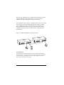
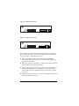
LFH4-M/LFH8-M
Mini Fast Hubs
Installation Guide
Table of Contents
CHAPTER 1. Introduction
1.1 Product Introduction . . . . . . . . . . . . . . . . . . . . . . . . . . . . . . . 2
1.2 Features . . . . . . . . . . . . . . . . . . . . . . . . . . . . . . . . . . . . . . . . . 3
1.3 Product Specifications . . . . . . . . . . . . . . . . . . . . . . . . . . . . . . 4
CHAPTER 2. Using the LFH Hub
2.1
2.2
2.3
2.4
2.5
Packing Checklist. . . . . . . . . . . . . . . . . . . . . . . . . . . . . . . . . . 5
Planning 100BASE-TX Networks . . . . . . . . . . . . . . . . . . . . . 5
Installation . . . . . . . . . . . . . . . . . . . . . . . . . . . . . . . . . . . . . . . 6
Mounting . . . . . . . . . . . . . . . . . . . . . . . . . . . . . . . . . . . . . . . . 8
Connecting LFH Hub . . . . . . . . . . . . . . . . . . . . . . . . . . . . . . 9
CHAPTER 3. LED Indicators
3.1
3.2
3.3
3.4
3.5
Power LED . . . . . . . . . . . . . . . . . . . . . . . . . . . . . . . . . . . . . . 11
Collision LED . . . . . . . . . . . . . . . . . . . . . . . . . . . . . . . . . . . . 11
Link/Activity LEDs. . . . . . . . . . . . . . . . . . . . . . . . . . . . . . . 12
Partition LED . . . . . . . . . . . . . . . . . . . . . . . . . . . . . . . . . . . . 12
System Status LEDs . . . . . . . . . . . . . . . . . . . . . . . . . . . . . . . 12
Limited Warranty. . . . . . . . . . . . . . . . . . . . . . . . . . . . . . . . . 13
Technical Support . . . . . . . . . . . . . . . . . . . . . . . . . . . . . . . . 13
Declaration of Conformity . . . . . . . . . . . . . . . . . . . . . . . 15
1
CHAPTER 1 Introduction
1.1 Product Introduction
Congratulations on your purchase of the LFH 4-port or 8-port Mini Fast
Ethernet Hub! The LFH4-M and LFH8-M are designed to give you the
ultimate in flexibility, ease-of-use, and reliability.
The LFH4-M and LFH8-M Mini Fast Ethernet Hubs are 100BASE-TX
multiport Class II repeaters for use with networks using Unshielded
Twisted Pair (UTP) category 5 cable or Shielded Twisted Pair (STP)
cable. The LFH hubs are simple to install, and Link/Activity, Partition,
and Collision LEDs provide convenient monitoring of the status of the
hub and of each port. For additional expansion, the hub offers an
Uplink port that makes it easy to cascade the hub to another Fast
Ethernet hub.
The LFH4-M/LFR8-M hubs can be placed on a tabletop or wallmounted, and provide the ideal solution for small to medium
100BASE-TX Fast Ethernet networks. The LFH hubs are designed
to comply with the IEEE 802.3u Fast Ethernet standard.
To insure network reliability, the LFH4-M and LFH8-M monitor each
port for signal quality and automatically disconnect stations transmitting noise, reconnecting them when the problem is resolved. Data
packets that exceed the maximum legal length for IEEE802.3 Ethernet
packets are automatically truncated. This prevents a device from
blocking the network by transmitting a continuous data stream or
excessively long packet. The LFH hubs completely retime and restore
full-amplitude waveforms for each retransmitted packet. A full-length
preamble is also generated, insuring packet integrity across the
network.
2
1.2 Features
▼ The LFH4-M provides four 100BASE-TX ports and the LFH8-M
provides eight 100BASE-TX ports for Fast Ethernet connectivity
▼ The LFH4-M/LFH8-M comply with the IEEE 802.3u Fast Ethernet
standard
▼ Supports Category 5 Unshielded Twisted Pair (UTP) or Shielded
Twisted Pair (STP) cable
▼ An Uplink port on the front panel enables the LFH4-M/LFH8-M to
be connected to another 100BASE-TX hub using a straight-through
cable
▼ Performs preamble regeneration, signal retiming and restoration,
extension of fragmented packets, automatic partitioning, and jabber
truncation
▼ Global Power and Collision LEDs and individual Partition and
Link/Activity LEDs indicate system status
▼ Comes with external AC/DC power supply (120VAC or 220VAC)
▼ FCC Class A, CE, UL, CUL, TUV certifications
▼ Five year limited warranty
3
1.3 Product Specifications
Standards
IEEE 803.3u 100BASE-TX Ethernet
Network Media 100BASE-TX Unshielded Twisted Pair cabling
(Category 5 UTP)
Max. Lengths
100 meter hub-to-station connection
5 meter hub-to-hub connection
Connectors
8/16 RJ45 connectors, one crossover ÒUplinkÓ port
LED indicators
Power, Collision, Partition, Link/Activity
Dimensions
221mm x 111mm x 26mm (L x W x H)
Environment
Temperature:
Humidity
Operating: 10 to 80%RH
Storage: 5 to 90%RH
Certifications
FCC Class A, CE, UL, CUL, TUV
Warranty
5-year limited
Operating: 0¡C to 40¡C
Storage: -20¡C to 70¡C
4
Chapter 2 Using the LFH Hub
2.1 Packing Checklist
Your LFH package should contain the following:
✓ An LFH4-M or LFH8-M Mini Fast Hub
✓ Mounting brackets and screws
✓ External AC/DC power adapter (120VAC or 220VAC)
✓ Installation Guide
If any of these items are missing, contact your dealer immediately.
2.2 Planning 100BASE-TX Networks
100BASE-TX networks need to be planned out slightly differently from
10BASE-T networks, because new hubs and new wiring configurations
are necessary. (10BASE-T hubs are incapable of sending or receiving data
at 100Mbps, so a 100BASE-TX network requires a 100BASE-TX hub.)
100BASE-TX supports a maximum length of 100 meters from a network
station to a hub. The total network diameter (the maximum cable
distance between any two stations on the network) is 205 meters for
100BASE-TX, as opposed to 500 meters for 10Mbps Ethernet. Because
100BASE-TX sends signals ten times faster than 10BASE-T, the collision
window (the time during which the network can detect a collision
between packets) is reduced to one-tenth the duration of the 10BASE-T
collision window, making the maximum network diameter smaller.
In a repeater environment, 100BASE-TX only allows a single layer of
cascaded hubs.
Switching hubs, such as LantronixÕs LSW8FA, may increase the
network diameter for 100BASE-TX networks by buffering data packets.
Each port can be connected to a separate LAN segment, each with a
maximum diameter of 205 meters, thereby increasing the overall
100BASE-TX network diameter.
5
Not only does 100BASE-TX have a different data transmission scheme,
it also has different cabling requirements. As previously noted,
100BASE-TX requires data-grade (Category 5) UTP cable.
Some installations have Category 5 cabling but do not have wall outlets
and wiring closet punch-down blocks that meet Category 5 requirements. 100BASE-TX requires that all wiring and accessories meet
EIA/TIA 568B specifications for proper operation. When wiring a
100BASE-TX network, make sure that the entire cable plant meets
specifications.
Figure 2-1 LFH4-M 100BASE-TX Network Example
LFH4-M
L
O
4
3
2
1
ON
PARTITI
LINK/ACT
PORT NO.
4
3
2
1
Uplink
L
O
4
3
2
1
ON
PARTITI
LINK/ACT
PORT NO.
4
3
2
1
Uplink
C
P
W
R
C
P
W
R
LFH4-M
2.3 Installation
The LFH Mini Fast Ethernet Hubs are easy to install and require no
special training. You should, however, read the following instructions
carefully before proceeding to install your hub. Figures 2-2 and 2-3
show the layout of the front panels.
6
Figure 2-2 LFH4-M Front Panel
L
O
C
PW
R
LFH4-M
4
3
2
1
PARTITION
LINK/ACT
PORT NO.
4
3
2
1
Uplink
Figure 2-3 LFH8-M Front Panel
L
O
C
PW
R
LFH4-M
4
3
2
1
PARTITION
LINK/ACT
PORT NO.
4
3
2
1
Uplink
The LFH Mini Fast Ethernet Hubs were designed for easy Òplug and
playÓ installation. Before you connect the LFH to other devices, there
are several issues you should keep in mind:
▼ When connecting the LFH to a workstation using unshielded
twisted pair cable, you must make sure that the cable length is not
greater than 100 meters
▼ When you connect two LFH hubs, you must make sure that the link
between them is not longer than 5 meters
▼ Network cable segments can be connected to, or disconnected from
the hub while the power is on. Plugging in or removing network
cables while your hub is operating will not interrupt the operation
of the hub
▼ When placing your LFH hub, you need to avoid dusty locations and
electromagnetically noisy areas
7
2.4 Mounting
Your LFH4-M or LFH8-M hub is delivered with a mounting bracket.
The LFH hub can be mounted to the wall or to the surface of a countertop by using the bracket and hanging the LFH hub on the wall using
the keyholes provided on the bottom of the hub.
If mounting the LFH hub is not your preference, you may choose to
place the LFH hub on a table or wiring closet shelf. Use the four selfadhesive rubber feet, which are provided with the hub for cushioning
purposes. Place them on the four corners of the bottom surface of the
hub.
8
2.5 Connecting the LFH Hub
Use the following procedures to connect 100BASE-TX network devices
to the hub:
LFH4-M
LFH8-M
Ports 1-4
Ports 1-8
Uplink Port
PC, Workstation
S
C
Server
S
C
Hub, Switch port
C
S
Hub, Switch uplink port
S
C
S = Straight Cable C = Crossover cable
NOTE: If the Uplink Port is being utilized on the LFH hub, the adjacent Port may not be used. Conversely, if that Port is being utilized, the
Uplink Port may not be connected.
The following table describes the two cable types:
Straight cable
Crossover cable
Pin 1
TD+
RD+
Pin 2
TD-
RD-
Pin 3
RD+
TD+
Pin 6
RD-
TD-
Make sure that the length of the straight-through cable between the
LFH hub and the other device does not exceed 100 meters, including all
patch cables and cross-connect wires.
Make sure that the length of the straight-through cable between two
hubs does not exceed 5 meters.
9
Chapter 3 LED Indicators
Figure 3-1 and Figure 3-2 show the LED indicators which indicate the
link status of each of the ports, whether the LFH hub is receiving
power, and the presence of network activity and collisions on the
network.
Figure 3-1 LFH4-M Front Panel LED Indicators
L
O
C
PW
R
LFH4-M
4
3
2
1
Partition
Link/Activity
PARTITION
LINK/ACT
PORT NO.
Figure 3-2 LFH8-M Front Panel LED Indicators
L
O
C
PW
R
LFH4-M
4
3
2
1
Partition
Link/Activity
PARTITION
LINK/ACT
PORT NO.
10
3.1 Power LED
The green LED on the front panel labeled PWR is used to indicate that
the LFH hub is receiving power and is turned on. If the LED is off,
check the following to isolate the problem:
▼ Make sure the power cord is properly connected to the power outlet
and is properly inserted into the power connection on the LFH hub
▼ Determine whether or not the outlet is functional by plugging
another device into the receptacle
3.2 Collision LED
The yellow collision LED is located on the front panel and is labeled
COL. This indicates that two (or more) stations on the network
attempted to transmit at the same time. When a collision occurs, all of
the stations involved will recognize the collision, wait a random
amount of time, and re-transmit. Collisions are normal in Ethernet
networks, though excessive collisions may indicate that your network
is overly congested. Other network problems can cause excessive collisions, including:
▼ Workstation cables exceeding the maximum length of 100 meters
▼ A total network diameter exceeding the maximum 205 meters
▼ Faulty Fast Ethernet adapters or other equipment on the network
11
3.3 Link/Activity LEDs
The Link/Activity LEDs on the front panel are associated with individual ports, indicating whether a device is detected on the other end
and whether or not the port has been automatically partitioned off.
The LFH hub monitors each port on the hub to determine whether or
not there is a device on the other end. If the cable is connected to a port
and a link is detected, the LED will light; otherwise the LED will not
light and the transmit and receive functions of the port will be disabled.
3.4 Partition LED
The yellow Partition LED is located on the front panel and labeled as
PARTITION. When there are too many collisions received from a
specific station(s), the hub will automatically partition it to prevent the
data transmission from other ports to those specific ports. When this
port is partitioned, the LED will be turned on.
3.5 System Status LEDs
LED summary table
PWR
Green
ON=Unit is receiving power
PARTITION
Yellow
ON=Port is partitioned
COL
Yellow
ON=Collision occurred
OFF=No collisions
LINK/ACT
Green
ON=Good link; Flashing=Activity
12
Limited Warranty
The LFH4-M and LFH8-M come with 5-year limited warranties. To
obtain LantronixÕs full warranty statement or if you experience problems with your unit, check our website (www.lantronix.com) or call
Lantronix for assistance.
Copyright © 1998, Lantronix. All rights reserved. No part of the
contents of this guide may be transmitted or reproduced in any
form or by any means without the written permission of Lantronix.
Technical Support
If problems occur during product operation, please check the hub
configuration settings, cables, connectors, network terminators and other
network components for compatibility.
Write a description of the problem, including what problems occurred and
when they occurred. Also, please have the following information ready
if calling for support services:
Model number & serial number
Purchase date
Network configuration
Application environment
Hardware, software (NOS) and the DOS version
Contact Lantronix technical support at 800-422-7044 within the United
States or 949-453-3990 outside of the United States. LantronixÕs technical support can also be reached via email at [email protected],
and via www.lantronix.com or via fax at 949-450-7226.
13
WARNING!
This device complies with part 15 of the FCC rules. Operation is subject
to the following conditions: (1) this device may not cause harmful
interference, and (2) this device must accept any interference received,
including that which may cause undesired operation. Operation of this
equipment in a residential area is likely to cause interference in which
case the user, at his or her own expense, will be required to take whatever measures may be required to correct the interference.
NOTE: The RJ45 ports are not for telephone use.
CAUTION:
Not for installation in air ducts, plenums or other environmental
air handling spaces. Changes or modifications to this device not
explicitly approved by Lantronix will void the userÕs authority
to operate this device.
14
Declaration of Conformity
(according to ISO/IEC Guide 22 and EN 45014)
ManufacturerÕs Name: Lantronix
ManufacturerÕs Address: 15353 Barranca Parkway
Irvine, CA 92618 USA
declares, that the product:
Product Name: Mini Fast Hubs
Model Number: LFH4-M, LFH8-M
conforms to the following standards:
EMC: EN55022(1988)/CISPR 22(1985)
Class B
EN60555-2(1987)
Class A
prEN55024-2(1990)/IE801-2(1991)
4KV CD, 8KV AD
prEN55024-3(1991)/IE801-3(1984)
3V V/m
prEN55024-4(1992)/IE801-4(1988)
1KV - (power line)
0.5KV - (signal line)
ManufacturerÕs Contact: Director of Quality Assurance
Lantronix
15353 Barranca Parkway
Irvine, CA 92618 USA
Tel: 949-453-3990
Fax: 949-453-3995
15
NOTES
16
15353 Barranca Parkway, Irvine, CA 92618
949-453-3990 ▼ Fax: 949-453-3995 ▼ Sales: 800-422-7055 ▼ Support: 800-422-7044
PART NO. 900-142 Rev.A