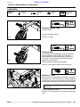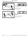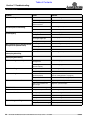
1
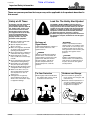
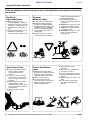
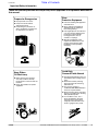
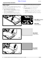
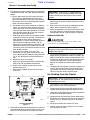
Table of Contents
Rotary Cutters
RCS3596, RCSM3596, RCS3510 & RCSM3510 Series
20521
312-708M
Operator’s Manual
!
Read the Operator’s manual entirely. When
you see this symbol, the subsequent
instructions and warnings are serious - follow
without exception. Your life and the lives of
others depend on it!
© Copyright 2006 Printed
6/26/06
Cover photo may show optional equipment
not supplied with standard unit.
Land Pride
Table of Contents
Table of Contents
Important Safety Information . . . . . . . . . . .1
Section 3: Operating Instructions . . . . . .15
Safety at All Times . . . . . . . . . . . . . . . . . . . . . . . . . 1
Look For The Safety Alert Symbol . . . . . . . . . . . . . 1
Safety Labels . . . . . . . . . . . . . . . . . . . . . . . . . . . . . 4
Operating Check List . . . . . . . . . . . . . . . . . . . . . . 15
Transporting . . . . . . . . . . . . . . . . . . . . . . . . . . . . . 15
Offset Function . . . . . . . . . . . . . . . . . . . . . . . . . . . 15
Cutting Instructions . . . . . . . . . . . . . . . . . . . . . . . 16
Crossing Steep Ditches & Banks . . . . . . . . . . . . . 16
General Operating Instructions . . . . . . . . . . . . . . 17
Introduction . . . . . . . . . . . . . . . . . . . . . . . .8
Application . . . . . . . . . . . . . . . . . . . . . . . . . . . . . . . 8
Using This Manual . . . . . . . . . . . . . . . . . . . . . . . . . 8
Terminology . . . . . . . . . . . . . . . . . . . . . . . . . . . 8
Definitions . . . . . . . . . . . . . . . . . . . . . . . . . . . . . 8
Owner Assistance . . . . . . . . . . . . . . . . . . . . . . . . . 8
Further Assistance . . . . . . . . . . . . . . . . . . . . . . 8
Section 1: Assembly and Set-Up . . . . . . . .9
Tractor Requirements . . . . . . . . . . . . . . . . . . . . . . 9
Weight & Horsepower . . . . . . . . . . . . . . . . . . . . 9
PTO Type & Speed . . . . . . . . . . . . . . . . . . . . . . 9
3-Point Hitch . . . . . . . . . . . . . . . . . . . . . . . . . . . 9
Dealer Preparations . . . . . . . . . . . . . . . . . . . . . . . . 9
Hitch Assembly . . . . . . . . . . . . . . . . . . . . . . . . . . 10
Tailwheel Assembly . . . . . . . . . . . . . . . . . . . . . . . 10
Driveline Installation . . . . . . . . . . . . . . . . . . . . . . . 10
Safety Guards (Optional) . . . . . . . . . . . . . . . . . . . 11
Front Chain Guards . . . . . . . . . . . . . . . . . . . . . 11
Rear Chain Guards . . . . . . . . . . . . . . . . . . . . . 11
Front Rubber Guards . . . . . . . . . . . . . . . . . . . 11
Rear Rubber Guards . . . . . . . . . . . . . . . . . . . . 11
Vent Plug Installation . . . . . . . . . . . . . . . . . . . . . . 12
Tractor Hook-Up . . . . . . . . . . . . . . . . . . . . . . . . . 12
PTO Hook-up . . . . . . . . . . . . . . . . . . . . . . . . . . . . 12
Hydraulic Hook-Up . . . . . . . . . . . . . . . . . . . . . 13
Un-Hooking from the Tractor . . . . . . . . . . . . . . . . 13
Section 4: Maintenance and Lubrication 18
Maintenance . . . . . . . . . . . . . . . . . . . . . . . . . . . . 18
Service Cutting Blades . . . . . . . . . . . . . . . . . . . . . 18
Driveline Clutch . . . . . . . . . . . . . . . . . . . . . . . . . . 19
Clutch Run-In . . . . . . . . . . . . . . . . . . . . . . . . . . . . 19
Clutch Assembly and Disassembly . . . . . . . . . . . 19
Flex Couplers . . . . . . . . . . . . . . . . . . . . . . . . . . . . 20
Skid Shoe Maintenance . . . . . . . . . . . . . . . . . . . . 20
Tractor Maintenance . . . . . . . . . . . . . . . . . . . . . . 20
Storage . . . . . . . . . . . . . . . . . . . . . . . . . . . . . . . . 20
Lubrication . . . . . . . . . . . . . . . . . . . . . . . . . . . . . . 21
Tailwheel Spindle Tube . . . . . . . . . . . . . . . . . . 21
Tailwheel Hub . . . . . . . . . . . . . . . . . . . . . . . . . 21
Gearbox & T-Box . . . . . . . . . . . . . . . . . . . . . . . 21
Offset Arms . . . . . . . . . . . . . . . . . . . . . . . . . . . 22
Driveline U-Joints . . . . . . . . . . . . . . . . . . . . . . 22
Driveline . . . . . . . . . . . . . . . . . . . . . . . . . . . . . 22
Flex Coupler . . . . . . . . . . . . . . . . . . . . . . . . . . 23
Ratchet Jack . . . . . . . . . . . . . . . . . . . . . . . . . . 23
Section 5: Specifications & Capacities . .24
Section 6: Features and Benefits . . . . . .25
Section 7: Troubleshooting . . . . . . . . . . .26
Section 2: Adjustments . . . . . . . . . . . . . .14
Section 8: Appendix . . . . . . . . . . . . . . . . .28
Leveling Procedure . . . . . . . . . . . . . . . . . . . . . . . 14
Minimum Cutting Height . . . . . . . . . . . . . . . . . 14
Cutter Height Adjustment . . . . . . . . . . . . . . . . . . . 14
Torque Values Chart for Common Bolt Sizes . . . . 28
Warranty . . . . . . . . . . . . . . . . . . . . . . . . . . . . . . . 29
© Copyright 2006 All rights Reserved
Land Pride provides this publication “as is” without warranty of any kind, either expressed or implied. While every precaution has been taken in the preparation of this manual, Land
Pride assumes no responsibility for errors or omissions. Neither is any liability assumed for damages resulting from the use of the information contained herein. Land Pride reserves
the right to revise and improve its products as it sees fit. This publication describes the state of this product at the time of its publication, and may not reflect the product in the future.
Land Pride is a registered trademark.
All other brands and product names are trademarks or registered trademarks of their respective holders.
Printed in the United States of America.
RCS3596, RCSM3596, RCS3510 & RCSM3510 Series Rotary Cutters 312-708M
6/26/06
Land Pride
▲
Table of Contents
Important Safety Information
Important Safety Information
These are common practices that may or may not be applicable to the products described in
this manual.
Safety at All Times
Look For The Safety Alert Symbol
Thoroughly read and understand
the instructions given in this
manual before operation. Refer to
the “Safety Label” section, read
all instructions noted on them.
Do not allow anyone to operate
this equipment who has not fully
read and comprehended this
manual and who has not been
properly trained in the safe
operation of the equipment.
The SAFETY ALERT SYMBOL indicates there is a
potential hazard to personal safety involved and extra
safety precaution must be taken. When you see this
symbol, be alert and carefully read the message that
follows it. In addition to design and configuration of
equipment, hazard control and accident prevention
are dependent upon the awareness, concern,
prudence and proper training of personnel involved in
the operation, transport, maintenance and storage of
equipment.
▲ Operator should be familiar with
all functions of the unit.
▲ Operate implement from the
driver’s seat only.
▲ Make sure all guards and shields
are in place and secured before
operating the implement.
▲ Do not leave tractor or implement
unattended with engine running.
▲ Dismounting from a moving
tractor could cause serious injury
or death.
▲ Do not stand between the tractor
and implement during hitching.
▲ Keep hands, feet, and clothing
away from power-driven parts.
▲ Wear snug fitting clothing to avoid
entanglement with moving parts.
▲ Watch out for wires, trees, etc.,
when raising implement. Make
sure all persons are clear of
working area.
▲ Turning tractor too tight may
cause implement to ride up on
wheels. This could result in injury
or equipment damage.
!
Be Aware of
Signal Words
A Signal word designates a degree or
level of hazard seriousness. The
signal words are:
! DANGER
Indicates an imminently hazardous
situation which, if not avoided, will
result in death or serious injury. This
signal word is limited to the most
extreme situations, typically for
machine components that, for
functional purposes, cannot be
guarded.
! WARNING
Indicates a potentially hazardous
situation which, if not avoided, could
result in death or serious injury, and
includes hazards that are exposed
when guards are removed. It may also
be used to alert against unsafe
practices.
! CAUTION
Indicates a potentially hazardous
situation which, if not avoided, may
result in minor or moderate injury. It
may also be used to alert against
unsafe practices.
For Your Protection
Shutdown and Storage
▲ Thoroughly read and understand
the “Safety Label” section, read all
instructions noted on them.
▲ Lower machine to ground, put
tractor in park, turn off engine, and
remove the key.
▲ Detach and store implements in a
area where children normally do
not play. Secure implement by
using blocks and supports.
OFF
REMO
VE
6/26/06
RCS3596, RCSM3596, RCS3510 & RCSM3510 Series Rotary Cutters 312-708M
1
Table of Contents
Land Pride
Important Safety Information
These are common practices that may or may not be applicable to the products described in
this manual.
Use Safety
Lights and Devices
Transport
Machinery Safely
▲ Slow moving tractors, selfpropelled equipment, and towed
implements can create a hazard
when driven on public roads. They
are difficult to see, especially at
night.
▲ Flashing warning lights and turn
signals are recommended
whenever driving on public roads.
▲ Comply with state and local laws.
▲ Maximum transport speed for
implement is 20 mph. DO NOT
EXCEED. Never travel at a speed
which does not allow adequate
control of steering and stopping.
Some rough terrains require a
slower speed.
▲ Sudden breaking can cause a
towed load to swerve and upset.
Use A Safety Chain
▲ A safety chain will help control
drawn machinery should it
separate from the tractor
drawbar.
▲ Use a chain with the strength
rating equal to or greater than
the gross weight of the towed
machinery.
▲ Attach the chain to the tractor
drawbar support or other
specified anchor location. Allow
only enough slack in the chain to
permit turning.
▲ Do not use safety chain for
towing.
2
Practice Safe Maintenance
▲ Understand procedure before
doing work. Use proper tools and
equipment, refer to Operator’s
Manual for additional information.
▲ Work in a clean dry area.
▲ Lower the implement to the
ground, put tractor in park, turn off
engine, and remove key before
performing maintenance.
RCS3596, RCSM3596, RCS3510 & RCSM3510 Series Rotary Cutters 312-708M
▲
▲
▲
▲
Reduce speed if towed load is not
equipped with breaks.
Use the following maximum
speed - tow load weight ratios as
a guideline:
20 mph when weight is less than
or equal to the weight of tractor.
10 mph when weight is double
the weight of tractor.
IMPORTANT: Do not tow a load
that is more than double the
weight of tractor.
▲ Allow implement to cool
completely.
▲ Do not grease or oil implement
while it is in operation.
▲ Inspect all parts. Make sure parts
are in good condition & installed
properly.
▲ Remove build-up of grease, oil or
debris.
▲ Remove all tools and unused
parts from implement before
operation.
6/26/06
Table of Contents
Land Pride
Important Safety Information
These are common practices that may or may not be applicable to the products described in
this manual.
Prepare for Emergencies
▲ Be prepared if a fire starts.
▲ Keep a first aid kit and fire
extinguisher handy.
▲ Keep emergency numbers for
doctor, ambulance, hospital and
fire department near phone.
Wear
Protective Equipment
▲ Protective clothing and equipment
should be worn.
▲ Wear clothing and equipment
appropriate for the job. Avoid
loose fitting clothing.
▲ Prolonged exposure to loud noise
can cause hearing impairment or
hearing loss. Wear suitable
hearing protection such as
earmuffs or earplugs.
▲ Operating equipment safely
requires the full attention of the
operator. Avoid wearing radio
headphones while operating
machinery.
911
Keep Riders
Off Machinery
▲ Riders obstruct the operator’s
view, they could be struck by
foreign objects or thrown from the
machine.
▲ Never allow children to operate
equipment.
6/26/06
Avoid High
Pressure Fluids Hazard
▲ Escaping fluid under pressure can
penetrate the skin causing serious
injury.
▲ Avoid the hazard by relieving
pressure before disconnecting
hydraulic lines.
▲ Use a piece of paper or
cardboard, NOT BODY PARTS, to
check for suspected leaks.
▲ Wear protective gloves and safety
glasses or goggles when working
with hydraulic systems.
▲ If an accident occurs, see a
doctor immediately. Any fluid
injected into the skin must be
surgically removed within a few
hours or gangrene may result.
RCS3596, RCSM3596, RCS3510 & RCSM3510 Series Rotary Cutters 312-708M
3
Table of Contents
Land Pride
Important Safety Information
Safety Labels
Your Rotary Cuttder comes equipped with all safety labels in
place. They were designed to help you safely operate your implement. Read and follow their directions.
1. Keep all safety labels clean and legible.
2. Replace all damaged or missing labels. To order new
labels go to your nearest Land Pride dealer or visit our
dealer locator at landpride.com.
3. Some new equipment installed during repair requires
safety labels to be affixed to the replaced component as
4.
specified by Land Pride. When ordering new components
make sure the correct safety labels are included in the
request.
Refer to this section for proper label placement.
To install new labels:
a. Clean the area the label is to be placed.
b. Spray soapy water on the surface where the label is to
be placed.
c. Peel backing from label. Press firmly onto the surface.
d. Squeeze out air bubbles with the edge of a credit card.
818-130C (Shown)
Caution 540 RPM
20701
818-240C
Caution 1000 RPM
818-229C
Amber Reflector
20701
818-230C
Red Reflector
20701
4
RCS3596, RCSM3596, RCS3510 & RCSM3510 Series Rotary Cutters 312-708M
6/26/06
Land Pride
Table of Contents
Important Safety Information
818-543C
Danger Guard Missing
20701
ROTATING DRIVELINE
KEEP AWAY!
818-552C
20701
20701
20701
6/26/06
Danger PTO Driveline
818-556C
Danger Thrown Object
818-798C
Warning Pinch Point
RCS3596, RCSM3596, RCS3510 & RCSM3510 Series Rotary Cutters 312-708M
5
Table of Contents
Land Pride
Important Safety Information
20701
818-564C
Chain Guard
818-830C
20701
Safety Combo
818-142C
20701
20701
6
RCS3596, RCSM3596, RCS3510 & RCSM3510 Series Rotary Cutters 312-708M
Rotating Driveline
838-094C
Warning: High Pressure
6/26/06
Land Pride
Table of Contents
Important Safety Information
818-540C
Danger Guard Missing
19958
20701
ROTATING DRIVELINE
KEEP AWAY!
818-552C
19958
20701
6/26/06
Danger PTO Driveline
RCS3596, RCSM3596, RCS3510 & RCSM3510 Series Rotary Cutters 312-708M
7
Table of Contents
Land Pride
Introduction
Introduction
Land Pride welcomes you to the growing family of new
product owners.
This Cutter has been designed with care and built by
skilled workers using quality materials. Proper assembly,
maintenance, and safe operating practices will help you
get years of satisfactory use from the machine.
Application
The Land Pride RCS(M)3596 and RCS(M)3510 Series
Side Shift Rotary Cutters are designed and built to clear
grass, weeds, and light brush up to two inches in
diameter from areas under orchard and grove trees,
beneath over-hanging hedge rows, or under fence lines
and guard railings. Both units have 14" side shift
capability to either side of the tractor with rear mounted
360 degree rotating tailwheels. These cutters are also
well suited for operation on gentle slopes and mildly
contoured approaches immediately adjacent to ponds,
lakes, streams, drainage ditches, and roadways. The
eight or ten foot cutting width and 2" to 12" cutting height
make them well suited for mowing pastures, set aside
acres, and row crop fields.
The RCS3596 is adapted for Category 1 or 2 semi-hitch
mounting and 50 to 120 horsepower tractors. The Model
RCS3510 is approved for Category 2 or 3 semi-hitch
attachment and 60-120 horsepower tractors. Due to the
offset nature of the hitch, this cutter utilizes a
“semi-mount” hitch configuration. The top link will not be
used and the tailwheels will always be in contact with the
ground. Both models are available with either 540 rpm or
1000 rpm PTO capability and offer standard driveline
clutch protection. A stump jumper is standard equipment
and safety guards are available. See “Features and
Benefits”, “Section 5” for additional information.
Using This Manual
• This Operator’s Manual is designed to help familiarize
•
•
you with safety, assembly, operation, adjustments,
troubleshooting, and maintenance. Read this manual
and follow the recommendations to help ensure safe
and efficient operation.
The information contained within this manual was
current at the time of printing. Some parts may change
slightly to assure you of the best performance.
To order a new Operator’s or Parts Manual contact
your authorized dealer. Manuals can also be
downloaded, free-of-charge from our website at
www.landpride.com or printed from the Land Pride
Service & Support Center by your dealer.
Terminology
“Right” or “Left” as used in this manual is determined by
facing the direction the machine will operate while in use
unless otherwise stated.
Definitions
IMPORTANT: A special point of information related
to its preceding topic. Land Pride’s intention is that
this information should be read and noted before
continuing.
Owner Assistance
The Warranty Registration card should be filled out by
the dealer at the time of purchase. This information is
necessary to provide you with quality customer service.
If customer service or repair parts are required contact a
Land Pride dealer. A dealer has trained personnel, repair
parts and equipment needed to service the Cutter.
The parts on your Cutter have been specially designed
and should only be replaced with genuine Land Pride
parts. Therefore, should your Cutter require replacement
parts go to your Land Pride Dealer.
Serial Number Plate
For prompt service always use the serial number and
model number when ordering parts from your Land Pride
dealer. Be sure to include your serial and model numbers in
correspondence also. Refer to Figure 1 for the location of
your serial number plate.
20701
Serial Number Plate Location
Figure 1
Further Assistance
Your dealer wants you to be satisfied with your new
Cutter. If for any reason you do not understand any part
of this manual or are not satisfied with the service
received, the following actions are suggested:
1. Discuss the matter with your dealership service
manager making sure he is aware of any problems
you may have and that he has had the opportunity to
assist you.
2. If you are still not satisfied, seek out the owner or
general manager of the dealership, explain the
problem and request assistance.
3. For further assistance write to:
Land Pride Service Department
1525 East North Street
P.O. Box 5060
Salina, Ks. 67402-5060
NOTE: A special point of information that the
operator must be aware of before continuing.
8
RCS3596, RCSM3596, RCS3510 & RCSM3510 Series Rotary Cutters 312-708M
E-mail address
[email protected]
6/26/06
Table of Contents
Land Pride
Section 1: Assembly and Set-Up
Section 1: Assembly and Set-Up
Tractor Requirements
Dealer Preparations
Weight & Horsepower
Read and understand the operator’s manual for your
cutter. An understanding of how it works will aid in the
assembly and setup of your cutter.
Tractor horsepower and weight must be capable of
controlling the cutter under all operating conditions.
Tractors outside the horsepower range must not be
used.
• RCS3596 cutters & RCSM3596
Semi-Mount
It is best to go through the Pre-Assembly Checklist
before assembling the cutter. Speed up your assembly
task and make the job safer by having all the needed
parts and equipment readily at hand.
30-120 HP
• RCS3510 & RCSM3510 cutters
Semi-Mount
50-120 HP
NOTE: Ballast may need to be added to your tractor
to maintain steering control. Refer to your tractor’s
operator manual to determine if one needs
additional ballast.
PTO Type & Speed
Tractor’s rear power take-off (PTO) speed and spline
type must be capable of matching the cutter’s PTO type
and speed.
• RCS3596 and RCS3510 cutters
540 RPM 1 3/8”-6 spline rear power take-off
• RCSM3596 and RCSM3510 cutters
1000 RPM 1 3/8”-21 spline rear power take-off
3-Point Hitch
The lower 3-Point arms of the 3-Point hitch must be
stabilized to prevent side-to-side movement. Most
tractors have sway blocks or adjustable chains for this
purpose. Category of hitch is dependent upon the series
of cutter being used.
• RCS3596 & RCSM3596 (Category l or ll hitch)
• RCS35510 & RCSM3510 (Category ll or lll hitch)
6/26/06
This Rotary Cutter has been partially assembled at the
factory. However, some assembly will be necessary to
attach the hitch, driveline and guards to the cutter.
Pre-Assembly Checklist
Check
Fasteners and pins that were shipped
with the cutter. NOTE: All hardware from
the factory has been installed in the
location where it will be used. If a part or
fastener is temporarily removed for
assembly reasons, remember where it
goes.Keep the parts separated.
Reference
Operator’s
Manual
Be sure the parts get used in the correct
location. By double checking while you
assemble, you will lessen the chance of
using a bolt incorrectly that may be
needed later.
Operator’s
Manual
All grease fittings are in place and
lubricated.
Section 4
Page 21
Safety labels are correctly located and
legible. Replace if damaged.
Safety
Information
Page 1
Red and amber reflectors are correctly
located and visible when the cutter is in
the transport position.
Safety
Information
Page 1
Have a minimum of 2 people at hand
while assembling the cutter.
Operator’s
Manual
Have a fork lift or loader along with
chains and safety stands that are sized
for the job ready for the assembly task.
Operator’s
Manual
RCS3596, RCSM3596, RCS3510 & RCSM3510 Series Rotary Cutters 312-708M
9
Table of Contents
Land Pride
Section 1: Assembly and Set-Up
Hitch Assembly
NOTE: Do not tighten hardware until assembly
is complete. Refer to “Torque Values Chart for
Common Bolt Sizes” on page 28.
Refer to Refer to Figure 1-1:
1. Install the offset arms (#2) to the cutter making sure
the pinch decals on the arms are to the top and front of
the cutter and assemble the mounting caps (#5).
Secure with bolts (#7) lockwashers (#11) and nuts (#9).
2. Assemble the hitch (#1) to offset arms (#2) inserting
the tubes (#6) in the offset arms and secure with bolts
(#8) lockwashers (#12) and nuts (#10).
3. Assemble rod end of cylinder (#3) to hitch lug with pin
(#13). Cylinder’s hydraulic elbows should be facing
away from offset arms.
4. Assemble the lift cylinder (#3) or ratchet jack (#14) to
lift lug on the deck and the rear axle and secure with
pins as shown.
20703
Tailwheel Assembly
Figure 1-2
Driveline Installation
Tailwheel Assembly
Refer to Refer to Figure 1-2:
1. Assemble tailwheel arms (#3) to rear axle with u-bolts
(#7) and flange nuts (#4).
2. Install tailwheel washer (#2) (larger diameter washer)
on the tire yoke (#1) and insert yoke into tailwheel
arms.
3. Place washer (#5) on yoke on top side of tailwheel
arms (#3) and secure with roll pin (#6).
1. Attach the slip-clutch end of the driveline to the
gearbox input shaft securely. Make certain that the
slip-clutch is fully onto the input shaft splines. Tighten
the conical dog pin on back side of slip-clutch to 45-50
ft-lb torque.
2. Secure the chain on the driveline to the driveline cone
to restrict outer shield from rotating.
20702
Hitch Assembly
Figure 1-1
10
RCS3596, RCSM3596, RCS3510 & RCSM3510 Series Rotary Cutters 312-708M
6/26/06
Table of Contents
Land Pride
Section 1: Assembly and Set-Up
Safety Guards (Optional)
!
Front Rubber Guards
DANGER!
Rotary Cutters have the ability to discharge objects at high
speeds; therefore, the use of front and rear safety guards is
strongly recommended when cutting along highways or in an
area where people may be present.
Refer to Figure 1-5:
Install each guard of the front rubber guards (#1) with the
carriage bolts (#2) and flange nuts (#3). RCS3596 is
shown. The RCS3510 has a center rubber guard that
will assemble between the left hand and right hand
rubber guards.
NOTE: Do not tighten hardware until assemblies
are complete. Refer to “Torque Values Chart for
Common Bolt Sizes” on page 28.
Front Chain Guards
Refer to Figure 1-3
Install the left hand (#2) and right hand (#1) front chain
guards with carriage bolts (#3), and flange nuts (#4). The
narrow end of the chain guards goes to the outside.
RCS3596 is shown. The RCS3510 has a center chain
guard that will assemble between the left hand and right
hand chain guards.
20706
Front Rubber Guards (RCS3596 Shown)
Figure 1-5
Rear Rubber Guards
Refer to Figure 1-6
Install the rear rubber guard (#1) and rear guard strap
(#2) with the carriage bolts (#3) and flange nuts (#4).
20704
Front Chain Guard
Figure 1-3
Rear Chain Guards
Refer to Figure 1-4
Install the rear chain guard (#1) with 1/2” -13 x 1 1/2” long
carriage bolts (#2), and 1/2” flange nuts (#3).
20711
Rear Rubber Guard
Figure 1-6
20705
Rear Chain Guard
Figure 1-4
6/26/06
RCS3596, RCSM3596, RCS3510 & RCSM3510 Series Rotary Cutters 312-708M
11
Table of Contents
Land Pride
Section 1: Assembly and Set-Up
Vent Plug Installation
Refer to Figure 1-7:
IMPORTANT: Cutters are shipped with a red plug in
the splitter gear box to prevent loss of oil during
shipping and handling. This plug must be replaced
with a vent plug before operating the cutter.
A vent plug for the splitter gearbox is included in a bag
with the manual. See your nearest Land Pride Dealer if
vent plug is missing. Remove temporary red plug from
top of splitter gearbox and replace with supplied vent
plug.
3. Remove lower linch pins and hitch pins from the deck.
4. Slowly back tractor up to the cutter while using the
tractor’s 3-point hydraulic control to adjust the lower
link arms up or down to match the tractor’s lower arm
pin holes to the cutter hitch pin holes. The lower lift
arms of a Category 2 tractor will be positioned to the
outside of the cutters lower hitch lugs on RCS35596 &
RCSM35596 cutters.
5. Re-insert hitch pins and secure with linch pins.
PTO Hook-up
If the cutter is to be used on more than one tractor, an
additional PTO shaft may be required - especially if a
quick hitch is used.
!
CAUTION!
Do not use a PTO adaptor with a quick hitch. A PTO adapter
will increase the strain on the tractor’s PTO shaft and can
damage the PTO shaft and mower driveline.
IMPORTANT: Avoid premature driveline
breakdown. A driveline that is operating must not
exceed an angle of 25 degrees up or down while
operating the 3-point lift. See Figure 1-8 below.
Vent Plug Location
Figure 1-7
Tractor Hook-Up
!
DANGER!
Crushing Hazard between tractor and implement. Do not allow
anyone to stand between the tractor and implement while
backing-up to an implement. Never operate the hydraulic
3-point lift controls while someone is directly behind the tractor.
!
DANGER!
Engage parking brake, shut off tractor and remove key before
dismounting from the tractor.
1. Locate the cutter on a flat level surface.
2. Determine the hitch category of the tractor that will be
used:
a. Category I tractors will have a lower hitch link
hole diameter of 7/8”. The top link hole diameter
(cutter end) will be 3/4".
b. Category II tractors will have a lower hitch link
hole diameter of 1 1/8”. The top link hole diameter
(cutter end) will be 1".
c. Category III tractors will have a lower hitch link
hole diameter of 1 7/16”. The top link hole
diameter (cutter end) will be 1 5/16".
12
13800
Maximum PTO driveline Movement During Operation
Figure 1-8
IMPORTANT: Do not attempt to operate a 540 RPM
driveline at 1,000 RPM or a 1,000 RPM driveline at
540 RPM. Many tractors provide both 540 and 1,000
RPM PTO speeds. Check your tractor’s manual to
determine its capabilities.
IMPORTANT: The PTO driveline may be too long for
some tractors. If the cutter is used on more than one
tractor, an additional PTO driveline may be required.
Refer to Figure 1-9 on page 13:
1. Start tractor and slowly engage tractor’s hydraulic
3-point to lift the lower arms until the cutter’s driveline
shaft is approximately level with tractor's PTO shaft.
2. Slide outer yoke end of driveline over the tractor's
PTO shaft and secure with the locking collar. Skip to
step 4 if driveline fits between tractor and cutter.
RCS3596, RCSM3596, RCS3510 & RCSM3510 Series Rotary Cutters 312-708M
6/26/06
Table of Contents
Land Pride
Section 1: Assembly and Set-Up
3. The driveline will require shortening if it is too long to
fit between the tractor and cutter. Shorten driveline as
follows:
a. Raise 3-point lower arms until cutter and tractor
PTO shafts are approximately level with each
other. Securely block cutter frame in this position.
Set tractor in park, shut tractor engine off, set park
brake and remove switch key.
b. Pull driveline apart into two sections as shown in
Figure 1-9. Attach the outer driveline universal
joint to the tractor PTO shaft and inner driveline
universal joint to the cutter gearbox shaft. Pull on
each driveline section to be sure the universal
joints are secured to the shafts.
c. Hold the driveline sections parallel to each other
to determine if they are too long. The inner and
outer shields on each section should end
approximately 1" short of reaching the universal
joint shield on the adjacent section (see “B”
dimension). If they are too long, measure 1" (“B”
dimension) back from the universal joint shield
and make a mark at this location on the inner and
outer driveline shields.
d. Cut off the inner shield at the mark (“X”
dimension). Cut the same amount off the inner
shaft (“X1” dimension). Repeat cut off procedure
(“Y” & “Y1” dimensions) to the outer driveline
half.
e. Remove all burrs and cuttings.
f. Apply multi-purpose grease to the inside of the
outer shaft and reassemble the driveline.
g. Attach inner driveline yoke end to the cutter
gearbox input shaft.
h. Attach outer driveline yoke end to the tractor's
PTO shaft.
IMPORTANT: A small chain is supplied with the
driveline. This chain must be attached to the inner
driveline shield and to the cutter to restrict shield
rotation.
5. Hook driveline safety chain in the hole in the inner
driveline guard. Attach the other end to the cutter’s
main frame.
6. Start tractor and raise cutter just enough to remove
blocks used to support the deck in step 3a.
7. Slowly engage the tractor’s hydraulic 3-point to lower
the cutter. Check for sufficient drawbar clearance.
Move drawbar ahead, aside or remove if required.
Hydraulic Hook-Up
!
CAUTION!
Do not over speed PTO. The cutter can be damage when
operated above its rated PTO RPM.
IMPORTANT: Do not engage tractor PTO until PTO
driveline is fully connected and hydraulic fluid has been
added to the reservoir.
1. If the cutter is equipped with a hydraulic cylinder for
height control, locate the hose from the cylinder, and
plug it into one of your tractor’s hydraulic outlets. This
is a one way cylinder, and as such, you only have one
hydraulic hose operation. You will now be able to
operate this cylinder from your tractor’s hydraulic
lever.
2. The offset hydraulic cylinder is a two way cylinder, and
as such, will have two hoses. Plug each hose into a
set of outlets. You now can offset your cutter left or
right by using your tractor’s hydraulic lever.
Un-Hooking from the Tractor
IMPORTANT: Always engage parking brake, shut
tractor engine off and remove switch key before
dismounting from tractor.
22311
Driveline Shortening
Figure 1-9
4. The driveline should now be moved back and forth to
insure that both ends are secured to the tractor and
cutter PTO shafts. Reattach any end that is loose.
6/26/06
1. Park cutter on a level solid hard surface. Place tractor
gear selector in park and set park brake.
2. Engage parking brake, shut tractor engine off and
remove switch key before dismounting from tractor.
3. Lower deck to level ground or onto blocks supporting
the deck just above ground level.
4. Disconnect hydraulic hose from tractor duplex outlet.
5. Disconnect any safety chains that may be connected
to the tractor. (i.e. driveline safety chain and check
chains)
6. Disconnect driveline from tractor PTO shaft.
7. Unhitch cutter from tractor 3-point arms and center
link if center link is used.
RCS3596, RCSM3596, RCS3510 & RCSM3510 Series Rotary Cutters 312-708M
13
Table of Contents
Land Pride
Section 2: Adjustments
Section 2: Adjustments
Leveling Procedure
There are three primary adjustments that should be
made prior to actual field operations:
a. Deck level from left to right
b. Tractor lower link height
c. Tailwheel height
Proper adjustment of each of these items will provide for
higher efficiency, improved cutting performance and
longer blade life. The following tools will be needed:
a. Pliable tape measure
b. Spirit or carpenter’s level
c. Open end or hex end wrench or socket set
d. Protective gloves
Having completed the “Tractor Hook-up”, locate the
tractor on a flat, level surface.
1. Use the tractor’s hydraulic 3-point control to lower the
cutter until the front of the skid shoes barely touch the
ground.
2. Place a spirit level or other suitable leveling device left
to right on the front of the cutter deck. Adjust either
one or both of the tractor’s lower link height
adjustments to level the deck from left to right. Some
tractors have only a single adjusting crank.
3. Similarly, place a level front to rear on either of the
main deck channels. Lower or raise tailwheel to level
the cutter deck from front to rear.
!
DANGER!
!
CAUTION!
Engage parking brake, disengage PTO, shut off tractor and
remove key before proceeding. Ensure that all moving parts
have come to a complete stop before dismounting from the
tractor.
Wear a pair of gloves when performing this operation. Go to the
back of the cutter and carefully rotate one dishpan and attached
two blades to the position shown in Figure 2-1. Avoid direct
contact with the cutting edge of the blade.
Minimum Cutting Height
Refer to Figure 2-1
Measure the distance from the end (cutting tip) of the
blade to the ground surface. This distance is the
minimum cutting height.
Cutter Height Adjustment
The unit is equipped with a ratchet jack or hydraulic
cylinder for cutting height adjustment. The hydraulic
selection includes stroke control spacers to set cutting
height. Stroke control spacers consist of cast steel
halves and a spring clip. To adjust height, simply extend
the hydraulic cylinder with the tractor hydraulics and
remove or replace the stroke control spacers for the
desired height. Each spacer is 1”. Retract the hydraulic
cylinder. Store stroke control spacers on hydraulic hose
near hydraulic cylinder.
Cutting Height
20712
Cutting Height
Figure 2-1
14
RCS3596, RCSM3596, RCS3510 & RCSM3510 Series Rotary Cutters 312-708M
6/26/06
Table of Contents
Land Pride
Section 3: Operating Instructions
Section 3: Operating Instructions
Operating Check List
It is absolutely essential that no one operates the Rotary
Cutter without first having read, fully understood and
become totally familiar with the Operator’s Manual. Make
sure the operator has paid particular attention to:
• Important Safety Information, pages 1 to 7
• Section 1: Assembly and Set-Up, page 9
• Section 2: Adjustments, page 14
• Section 3: Operating Instructions, page 15
• Section 4: Maintenance and Lubrication, page 18
In addition to design and configuration of equipment,
hazard control and accident prevention are dependent
upon the awareness, concern, prudence and proper
training involved in the operation, transport,
maintenance and storage of equipment. Before
beginning to cut, the following inspection should be
performed.
8. With the PTO disengaged and completely stopped,
check cutting blades for sharpness.
9. (Lift-Type Cutter) Adjust tractor lower 3-point arms
such that the PTO driveline is approximately level.
10. Set tractor throttle to idle or slightly above idle and
slowly engage PTO. Initial start-up vibration is normal
and should stop after a few revolutions. Stop PTO
rotation if vibration continues. Wait for the PTO to
come to a complete stop and then dismount from the
tractor to check for probable causes.
11. Once the cutter is running smoothly, increase tractor
PTO speed to the rated PTO speed. Stop PTO
rotation immediately if vibration occurs and wait for
PTO to come to a complete stop and then dismount
from the tractor to check for probable causes.
IMPORTANT: Do not exceed rated PTO speed of
the cutter. Excessive engine speed will cause
damage to the power train components.
Transporting
Operating Checklist
!
Check
“Important Safety Information” in
this Manual.
Reference
page 1 - 7
Be certain all guards and shields
are in place.
Section 1
Check oil level in gearboxes.
Section 4
Page 21
IMPORTANT: Always disengage the tractor’s PTO
before raising the cutter to transport position.
Check that all plugs in gearbox
have been replaced properly.
Section 4
Page 21
Lubricate the cutter as needed.
Refer to “Maintenance and
Lubrication”.
Section 4
Page 21
Be sure nuts and bolts are tight.
Section 8
1. When raising the cutter to the transport position be
sure that driveline does not contact tractor or cutter.
2. Be sure to reduce tractor ground speed when turning;
and leave enough clearance so the cutter does not
contact obstacles such as buildings, trees or fences.
3. Limit transport speed to 20 mph. Transport only with a
tractor of sufficient size and horsepower. When
traveling on roadways, transport in such a way that
faster moving vehicles may pass you safely.
4. When traveling over rough or hilly terrain, shift tractor
to a lower gear.
CAUTION!
When traveling on public roads at night or during the day, use
accessory lights and devices for adequate warning to operators
of other vehicles. Comply with all federal, state and local laws
.
Make the following inspections after hooking-up to the
cutter. See Tractor Hook-Up instructions beginning on
page 10. Make certain the PTO is disengaged and
completely stopped before continuing.
4. Inspect tractor safety equipment to make sure it is in
good working condition.
5. Carefully raise and lower the implement to ensure that
the drawbar, tires, and other equipment on the tractor
do not contact the frame or PTO driveline.
6. Check all hoses and wires to be sure that they will not
contact PTO driveline. Check PTO guards to make
certain they are in good condition and in place.
7. Inspect Hydraulic hoses for wear, damage and
hydraulic leaks. See “Avoid High Pressure Fluids Hazard”
on page 3. Replace damaged and worn hoses with
genuine Land Pride parts.
6/26/06
Offset Function
The main feature of your RCS35 Series Rotary Cutter is
the hydraulic offset design. Being able to offset the cutter
on the go increases your cutting efficiencies. Being able
to maneuver the cutter versus steering around obstacles
greatly increases your productivity. Easily operated by
your tractor’s hydraulic lever, offsetting the cutter is at
your fingertips. See “Hydraulic Hook-Up” on page 13.
RCS3596, RCSM3596, RCS3510 & RCSM3510 Series Rotary Cutters 312-708M
15
Table of Contents
Land Pride
Section 3: Operating Instructions
Cutting Instructions
!
DANGER!
!
DANGER!
The use of front & rear safety guards is strongly recommended
to prevent injury or death caused by thrown objects! Gearbox
shields must be secured in place when operating to avoid injury
or death from entanglement in rotating drivelines.
Rotary Cutters have the ability to discharge objects at high
speeds. Therefore, the use of front & rear safety guards is
strongly recommended when cutting along highways or in an
area where people may be present!
!
CAUTION!
Damage to the tractor’s PTO components and/or driveline
components can cause the driveline to come loose and cause
bodily injury to the operator and others.
WARNING!
The RCS35 series cutter is designed to cut grass and brush up
to 1” in diameter. Using his cutter for any other type of work
can damage the drive components, deck and support frame.
!
5. This cutter was designed to cut grass and medium
brush in right-of-ways, pastures and for shredding row
crop residues.
Crossing Steep Ditches & Banks
Do not over speed PTO or machine damage may result. The 8’
model in this series is available in 540 RPM. The 10’ model in
this series is available in 540 RPM or 1000 RPM. Know what
your tractor requirements are.
!
• Size of the tractor operating the cutter.
CAUTION!
Damage may occur if exceeding the rated cutting capacity of
the cutter!
!
1. Thoroughly Inspect the area to be cut for debris and
unforeseen objects. Mark any potential hazards.
2. Start the machine slowly allowing the cutter blades to
become aligned properly before going to full power.
3. It is important to maintain correct RPM PTO speed.
Loss of PTO speed will allow the blades to hinge back
and result in ragged, uneven cutting.
4. Never run fast enough to overload the tractor or cutter.
Ground speed depends on two things:
• The density of the material being cut.
DANGER!
Do not use deck as a fan. Cutting blades are not properly
designed or guarded for this use. Using the deck as a fan can
result in injury and/or death.
! DANGER!
Do not operate and/or travel across steep inclines where a
tractor can roll-over resulting in serious injury or death.
Consult your tractor’s manual for acceptable inclines the
tractor is capable of traveling across.
IMPORTANT: Avoid catching the hydraulic hoses on
brush, post, stumps, and other protrusions that
could damage and/or break them.
Refer to Figure 3-1:
!
WARNING!
IMPORTANT: Always cross steep ditches and
banks at a diagonal. Never cross straight across
and/or never back into a steep ditch or bank.
Cutting over ditches and backing up hills can tilt the
cutter’s back side up excessively resulting in the driveline
“Bottoming Out” and causing serious damage to the
tractor PTO components, cutter gearbox and driveline.
Bottoming out is when the driveline shaft has shorten to
the point it is pressing against the gearbox and tractor
PTO shafts. Do not operate the cutter at an angle
exceeding 25 degrees up or down or at any angle that will
force the driveline to bind and/or hit the tractor drawbar.
Right
Ditch / Bank
Ditch / Bank
NOTE: Your cutter is equipped with free swinging
cutting blades to reduce shock loads to the cutter if
striking obstacles.
16
RCS3596, RCSM3596, RCS3510 & RCSM3510 Series Rotary Cutters 312-708M
Wrong
Crossing Steep Ditches and Banks
Figure 3-1
6/26/06
Table of Contents
Land Pride
Section 3: Operating Instructions
General Operating Instructions
Now that you have familiarized yourself with the
Operator’s Manual, completed the Operator’s Checklist,
properly attached your Cutter to your tractor, made the
right leveling adjustments, and preset your cutting
height, you’re almost ready to begin using your Land
Pride Side Shift Cutter.
It’s now time to do a running operational safety check. If
at any time during this safety check you detect a
malfunction in either the cutter or tractor, shut the tractor
off immediately, remove the key, and make necessary
repairs or adjustments before continuing on. With the
tractor’s park brake engaged, the tractor PTO
disengaged, and the cutter resting on the ground, start
the tractor and back the tractor throttle off until the engine
is at low idle.
With the tractor’s rear hydraulic lift control lever, raise the
cutter to transport position making sure that the driveline
is not in a bind and does not come in contact with the
cutter frame. Lower the cutter to the ground and, with the
tractor still at low idle, engage the PTO. If everything is
running smoothly at this point increase the engine rpm
until the tractor’s engine reaches full PTO operating
speed which will be either 540 or 1000 rpm.
Slowly raise the cutter to transport height to make sure
the driveline does not bind or chatter. Return the engine
to low idle, disengage the PTO, and position the
adjustable stops on the tractor’s hydraulic lift lever so the
cutter can be consistently returned to the same cutting
and transport height.
and cutter. Slow down in turns and avoid sharp turns if at
all possible. Remember to look back often.
Now you’re prepared and well briefed so lets begin
cutting. Reduce the tractor’s engine rpm, lower the cutter
to the ground, engage the PTO, raise the engine rpm to
the appropriate PTO speed, and begin mowing. As you
travel forward, use your auxiliary hydraulic control lever
to shift your cutter from side to side so you can develop
a feeling for side shift response time. Avoid making side
shifts when not in forward motion as this is hard on the
cutter and tractor.
When you can’t make a wide turn and you need to
reverse direction, you will need to lift the cutter into
transport position to make a tight turn. Try increasing or
decreasing ground speed to determine the effect on
quality of cut. With a little practice you will be pleased
with what you and your Land Pride Side Shift Cutter can
do.
When you are done mowing, need to take a break, or just
need to make a few adjustments to the cutter, remember
to always do the following: Reduce the tractor’s engine
rpm, disengage the PTO, stop on level ground, set the
park brake, turn off the engine, and remove the key. If
your tractor does not have a “live PTO” and you are trying
to stop, the tractor can be pushed forward by the
momentum of the cutter’s rotating blades.
You should now be ready to move to the cutting site to
begin mowing. You should have inspected and only be
cutting in an area you are familiar with which is free of
debris and unseen objects. Never assume an area is
clear. Extremely tall grass should be cut twice to detect
potential hazards. In the event you do strike an object,
stop the tractor and cutter immediately to inspect the
cutter and make any necessary repairs before resuming
operation. It pays to inspect a new area and to develop a
plan before you cut.
Normal mowing speed will be between 2-5 mph and you
will need to maintain 540 or 1000 rpm PTO speed to
produce a clean cut. Make a tractor gear and range
selection that will maintain this combination. Generally,
the quality of cut will be better at lower ground speeds
and cutting denser ground cover will create the need to
slow down.
In certain conditions tractor tires will roll grasses down,
resulting in an uneven cutting height when the grass fails
to rebound before being cut. When this happens you may
need to reverse the cutting direction and double cut to
achieve the desired finish. You will want to avoid very low
cutting heights especially on extremely uneven terrain.
Always cut downward on slopes and avoid crossing the
face of steep slopes. Avoid sharp drops and cross
diagonally through dips to prevent hanging up the tractor
6/26/06
RCS3596, RCSM3596, RCS3510 & RCSM3510 Series Rotary Cutters 312-708M
17
Table of Contents
Land Pride
Section 4: Maintenance and Lubrication
Section 4: Maintenance and Lubrication
Maintenance
Proper servicing and adjustment is the key to the long life
of any implement. With careful and systematic
inspection, you can avoid costly maintenance, time and
repair.
After using your cutter for several hours, check all bolts
to be sure they are tight.
Replace any worn, damaged or illegible safety labels by
obtaining new labels from your Land Pride Dealer.
!
DANGER!
!
WARNING!
Always disconnect main driveline from tractor PTO before
servicing the underside of the cutter deck. Cutter can be
engaged if tractor is started resulting in damage to the cutter,
bodily injury and/or death.
Always secure cutter deck in the up position with solid supports
before servicing the underside of the cutter. Never work under
equipment supported by hydraulics. Hydraulics can drop
equipment if controls are actuated or if hydraulic lines burst.
Either situation can drop the cutter instantly even when power
to the hydraulics is shut off.
f. Both blades should weigh the same after
sharpening with not more than 1 oz. difference.
IMPORTANT: Unbalanced blades will cause
excessive vibration which can damage gearbox
bearings and create structural cracks in cutter
housing.
9. Make certain when installing cutter blades that the
blades on one spindle is positioned 90 degrees to the
blades on the other spindle as shown in Figure 4-1.
10. Examine blade bolts for excessive wear and replace if
necessary. To replace blade bolts:
a. Order Land Pride blade bolt part #802-277C and
lock nut #803-170C.
b. Refer to Figure 4-1. Carefully check the cutting
edges of the blades in relation to the blade carrier
rotation to ensure correct blade placement.
c. Torque blade lock nut to 450 ft. pounds. An
extended cheater bar may be required.
CCW
CC
Service Cutting Blades
IMPORTANT: Blades must be ordered and replaced
in pairs. Order only genuine Land Pride blades.
Land Pride blades are made of special heat treated
alloy steel. Substitute blades may not meet Land
Pride’s specifications and may be dangerous to
operate.
6. Always disconnect main driveline from tractor PTO
and secure cutter deck in the up position with solid
supports before servicing the underside of the cutter.
7. Always inspect cutting blades before each use. Make
certain they are properly installed and are in good
working condition. Replace any blade that is
damaged, worn, bent, or excessively nicked. Small
nicks can be ground out when sharpening.
8. Both blades should be sharpened at the same angle
as the original cutting edge and must be replaced or
re-ground at the same time to maintain proper
balance in the cutting unit. The following precautions
should be taken when sharpening the blades:
a. Do not remove more material than necessary.
b. Do not heat and pound out a cutting edge.
c. Do not grind blades to a razor edge. Leave a blunt
cutting edge approximately 1/16” thick.
d. Always grind the cutting edge so that the end of the
blade remains square to the cutting edge and not
rounded.
e. Do not sharpen the back side of the blade.
18
Blade Positioning and Rotational Directional
Figure 4-1
Land Pride Cutter Blade Parts
Part No.
Part Description
820-195C
820-196C
820-137C
820-112C
802-277C
803-170C
804-147C
RCR3596 CUTTER BLADE 1/2 x 4 x 20 CCW
RCR3596 CUTTER BLADE 1/2 x 4 x 20 CW
RCR3510 CUTTER BLADE 1/2 x 4 x 25 CCW
RCR3510 CUTTER BLADE 1/2 x 4 x 25 CW
BLADE BOLT 1 1/8-12 x 3 7/16 WITH KEY
NUT HEX TOP LOCK 1 1/8-12 PLATE
WASHER FLAT 1 HARD ASTMF436 PN
Land Pride Optional Low Lift Cutter Blades
820-210C
820-211C
820-193C
820-209C
RCS3596, RCSM3596, RCS3510 & RCSM3510 Series Rotary Cutters 312-708M
RCR3596 BLADE 1/2X4X20.5 LL CCW
RCR3596 BLADE 1/2X4X20.5 LL CW
RCR3510 BLADE 1/2X4X25 LL CCW
RCR3510 BLADE 1/2X4X25 LL CW
6/26/06
Table of Contents
Land Pride
Section 4: Maintenance and Lubrication
Driveline Clutch
Clutch Assembly and Disassembly
Cutter drive components are protected from shock loads
by a slip-clutch. The clutch must be capable of slippage
during operation to protect the gearbox, driveline and
other drivetrain parts.
Refer to Figure 4-3:
If the clutch run-in procedure, see “Clutch Run-In” above,
indicated that one or more friction discs did not slip, the
clutch must be disassembled to separate the friction discs.
Prior to initial operation and after long periods of
inactivity, the clutch should be “run-in” to remove any
oxidation that may have accumulated on the friction
surfaces.
Disassembly of the clutch is simply a matter of first
removing the spring retainer nuts (#1), springs (#2) and
bolts (#3) from the assembly. Each friction disc (#4) must
then be separated from the metal surface adjacent to it.
Inspect all parts for excessive wear and condition. Clean
all parts that do not require replacement.
!
CAUTION!
Engage parking brake, disengage PTO, shut off tractor, and
remove key before making any of the following adjustments.
4-Plate Slip Clutch
540 RPM (shown)
Clutch Run-In
Refer to Figure 4-2:
1. Using a pencil or other marker, scribe a line across the
exposed edges of the clutch plates and friction discs.
14714
Clutch Disassembly
Figure 4-3
13693
Clutch
Figure 4-2
2. Carefully loosen each of the 8 spring retainer nuts on
the clutch housing a total of EXACTLY 2 revolutions. It
will be necessary to hold the hex end of the retainer
bolt in order to count the exact number of revolutions.
3. Start the tractor and engage the PTO drive for 2-3
seconds to permit slippage of the clutch surfaces.
Disengage the PTO, then re-engage a second time for
2-3 seconds. Disengage the PTO, shut off tractor and
remove key. Wait for all components to stop before
dismounting from tractor.
4. Inspect the clutch and ensure that the scribed
markings made on the clutch plates have changed
position. If any two marks on a friction disc and plate
are still aligned, such indicates that slippage has not
occurred and the clutch must be disassembled to
separate the friction discs, see “Clutch Assembly
and Disassembly” below.
5. Tighten each of the 8 spring retainer nuts on the clutch
housing EXACTLY 2 revolutions to restore the original
clutch setting pressure.
6. The clutch should be checked during the first hour of
cutting and periodically each week. An additional set
of scribe marks can be added to check for slippage.
See “Clutch Assembly and Disassembly” below to
adjust for proper spring length.
6/26/06
The original friction disc thickness is 1/8" (3.2mm) and
should be replaced if the thickness falls below 3/64"
(1.1mm). If the clutches have been slipped to the point of
“smoking”, the friction discs may be damaged and should
be replaced. Heat build-up may also affect the yoke
joints.
Refer to Figure 4-4:
Install new friction discs if needed and reassemble all
components in proper order. Progressively tighten each
spring retainer bolt until the spring length is between 1.120
to 1.110 inches for 540 RPM and 1.020 to 1.010 inches
for 1000 RPM.
20903
Clutch Adjustment
Figure 4-4
RCS3596, RCSM3596, RCS3510 & RCSM3510 Series Rotary Cutters 312-708M
19
Table of Contents
Land Pride
Section 4: Maintenance and Lubrication
Flex Couplers
4. Repeat on opposite side.
Refer to Figure 4-5:
Replace two rubber discs (#1) (Land Pride Part No.
1785273) as follows: Refer to land Pride’s Parts Manual
312-708P if additional repair parts are required.
1. Insert three bolts (#3) through the holes in flange
weldment (#7).
2. Place beaded washers (#2) over the three bolts with
bead facing rubber disc (#1).
3. Place bushings (#6), rubber disc (#1), washers (#5),
2nd rubber disc (#1), 2nd bushing (#6) and 2nd
washer (5) over the three bolts as shown.
4. Secure with nuts (#4). Do not tighten.
5. Insert three bolts (#3) through the holes in flanged
hub (#8).
6. Repeat steps 2 through 4.
7. Tighten nuts (#4) evenly with nuts torqued 35 to
40 ft-lb. Beaded washers (#2) should be imbedded
halfway into the rubber disc.
Land Pride Skid Shoe Replacement Parts
Part No.
Part Description
312-602D
802-466C
803-198C
SKID SHOE
PLOW 3/8” - 16 x 1 1/4” GR5
NUT HEX WHIZ 3/8-16 PLT
22454
Skid Shoe Replacement
Figure 4-6
Tractor Maintenance
One of the most important things you can do to prevent
hydraulic system problems is to ensure that your tractor's
reservoir remains free of dirt and contamination.
Use a clean cloth to wipe the hose ends before attaching
them to your tractor. Replace the filter element for your
tractor’s hydraulic system at the prescribed intervals.
These simple maintenances will go a long way to prevent
the occurrence of cartridge valve and hydraulic cylinder
problems on the Rotary Cutter.
Storage
14560
Flex Couplers
Figure 4-5
Skid Shoe Maintenance
!
WARNING!
Excessive wear on skid shoes may cause inadequate operation
of cutter and create a safety hazard!
There are two skid shoes mounted on the cutter sides.
Check both skid shoes for wear and replace if necessary.
Order only genuine Land Pride parts from your local
Land Pride Dealer.
Refer to Figure 4-6:
1. Remove 3/8" hex whiz nuts (#3), 3/8" plow bolts (#2)
and skid shoe (#1) as shown.
2. Plow bolts should be checked for wear and replaced if
necessary.
3. Attach new skid shoe (#1) to cutter with existing
3/8” plow bolts (#2) and secure with 3/8" hex whiz
nuts. Torque to 31 ft. lbs.
20
At the end of the working season or when the cutter will
not be used for a long period, it is good practice to clean
off any dirt or grease that may have accumulated on the
cutter and any of the moving parts.
1. Clean the cutter as necessary.
2.Check the blades for wear and replace if necessary, see
“Service Cutting Blades”, Page 18.
3. Inspect the cutter for loose, damaged or worn parts
and adjust or replace as needed.
4. Lubricate as noted in “Lubrication”, page 21.
5. Store the cutter inside if possible for longer cutter life.
6. Repaint parts where paint is worn or scratched to
prevent rust. Ask your dealer for Aerosol Land Pride
touch-up paint.
Land Pride Touch-up Paints
Part No.
Part Description
821-011C
821-002C
821-054C
821-058C
PAINT LP BEIGE SPRAY CAN
PAINT GP BLACK SPRAY CAN
PAINT MEDIUM RED SPRAY CAN
PAINT GREEN SPRAY CAN
RCS3596, RCSM3596, RCS3510 & RCSM3510 Series Rotary Cutters 312-708M
6/26/06
Table of Contents
Land Pride
Section 4: Maintenance and Lubrication
Lubrication
Lubrication
Legend
Multi-purpose
spray lube
Multi-purpose
grease lube
Multi-purpose
oil lube
50
Intervals in hours
at which lubrication
is required
24
Hours
Tailwheel Spindle Tube
Lift-Type Cutter
Type of Lubrication: Grease
20701
Quantity = 6 pumps
8
Hours
Tailwheel Hub
20701
The tailwheel hub is equipped with a relief hole located
directly opposite the grease fitting. The relief hole
releases pressure from inside the hub casting when it
is greased. The hub should be greased until grease
purges from the relief hole.
Type of Lubrication: Multi-purpose Grease
Quantity = Until grease purges from the relief hole
8
Hours
Gearbox & T-Box
Check oil level in the gearbox by removing the side plug in
the gearbox case. If the oil level is low, remove the top plug
in the gearbox case and fill with EP90 oil until oil flows from
the side port of gearbox case. Reinstall plugs and tighten.
20701
NOTE: Do not overfill! Cutter should be level when
checking oil.
Type of Lubrication: EP90 Oil
Quantity = Fill until oil flows from the side port of gearbox
case.
6/26/06
RCS3596, RCSM3596, RCS3510 & RCSM3510 Series Rotary Cutters 312-708M
21
Table of Contents
Land Pride
Section 4: Maintenance and Lubrication
24
Hours
Offset Arms
Type of Lubrication: Grease
20701
Quantity = 6 pumps
8
Hours
Driveline U-Joints
Type of Lubrication: Grease
13755
Quantity = 6 pumps
20
Hours
Driveline
19964
22
Quantity = Clean & coat the inner tube of the driveline
with a light film of grease and then reassemble.
RCS3596, RCSM3596, RCS3510 & RCSM3510 Series Rotary Cutters 312-708M
6/26/06
Land Pride
Table of Contents
Section 4: Maintenance and Lubrication
8
Hours
Flex Coupler
Type of Lubrication: Grease
16276
Quantity = As required
As
Required
Ratchet Jack
(If equipped)
Type of Lubrication: Multi-Purpose
14176
6/26/06
Quantity = As required
RCS3596, RCSM3596, RCS3510 & RCSM3510 Series Rotary Cutters 312-708M
23
Table of Contents
Land Pride
Section 5: Specifications & Capacities
Section 5: Specifications & Capacities
RCS(M)3596 & RCS(M)3510 Series
Hitch
RCS3596 (540 RPM)
RCSM3596 (1000 RPM)
RCS3510 (540 RPM)
RCSM3510 (1000 RPM)
Category 1 & 2, Semi-Mount
Quick Hitch adaptable
Category 2 & 3, Semi-Mount
Quick-Hitch adaptable
Offset Capability
13"
Working Width
8’ 2”
10’
Overall Width
8’ 6 1/2”
10’ 5”
Overall Length
Machine Weight
(With Front & Rear Chain Guards &
Hydraulic Cylinders)
Blade Tip Speed
105”
110”
2062 lbs.
2400 lbs.
540 RPM 14,223 fpm
1000 RPM 14,442 fpm
540 RPM 17,291 fpm
1000 RPM 17,569 fpm
Deck Material Thickness
10 gauge
Gearbox Rating H.P.
Gearbox (Speed up beveled gears)
H.P. Rating (PTO)
Center - 120 HP Outboard 100 HP
540 rpm or 1000 rpm PTO Driven Gearbox
Cast Iron Housing, Beveled Gears
30 - 120
50 - 120
Cutting Height
2” - 12”
Cutting Capacity
Safety Guards
2”
Front & Rear Chain/ Front & Rear Rubber
Skids
Replaceable
Deck Height
Blades
Stump Jumper
Driveline
24
9 5/8”
1/2" x 4" Heat Treated
Free-Swinging Suction Blades
Round Pan 3/16”
Cat 4, w/Equal Angle U-Joint
Cat 4, w/Equal Angle U-Joint
Driveline Safety Protection
540 rpm - 4 plate slip-clutch
1000 rpm - 2 plate slip-clutch
Tailwheel
2 ea. 6” X 9” X 21” Laminated
RCS3596, RCSM3596, RCS3510 & RCSM3510 Series Rotary Cutters 312-708M
6/26/06
Table of Contents
Land Pride
Section 6: Features and Benefits
Section 6: Features and Benefits
RCS(M)3596 & RCS(M)3510 Series
Features
Surpassed rugged
industry standards
Benefits
All Land Pride Cutters have been designed and tested and meet rigorous voluntary testing
procedures specified by ANSI.
Tractor HP range
30-120 HP.
540 or 1000 RPM
Fits wider variety of tractors.
5 Year limited
gearbox warranty
3 Gearboxes
Gearbox HP rating
Splined rubber flex-couplers
between center and
outboard gearboxes
Slip-clutch protection
on main driveline
Semi-mount categories
Offset capability
Cutting Width
10 Gauge deck, fully welded
1/4” Thick sidewalls
Obstacle free underside
Round back design
Chain or rubber guards
Full length skids with
replaceable shoes
Splined blade hub
Shows our confidence in the gearbox integrity.
Allows equal torque to be spread to left and right gearbox.
120 Horsepower on splitter gearbox and 100 HP on wing gearboxes.
Protects the driveline and gearboxes from hard objects in the blade path.
Slip-clutch is more convenient than shear-bolt, protects gearbox against sudden impact.
Semi-mount allows for hydraulic offset. (Cat. 1 & 2 on 96” & Cat 2 & 3 on 10’-0”)
Offset 13” right and left, hydraulically for time saving maneuverability.
8’-2” on RCS3596 and 10’-0” on RCS3510.
Fully welded deck adds rigidity.
Protects sidewalls from thrown objects.
Underside of deck is free of reinforcement members which tend to allow material to lodge.
Allows for cleaner and efficient discharge of material, helps eliminate damage to rear
corners by not sticking out.
Reduces flying debris.
Adds reinforcement to side panels. Replaceable shoes allow for change before wearing
through to weld-on piece.
Splined blade hub offers tight non-slipping attachment to output shaft.
3/16” Round stump jumper
Standard stump jumper aids in sliding over obstructions, which helps protect gearbox
output shaft.
1/2” x 4” Blade bar
Heavy-duty blade bar adds support to stump jumper as well as gearbox output shaft.
1/2” x 4” Heat-treated blades
Heat-treated blades last longer than non heat-treated blades.
2” Diameter cutting capacity
Aids in cutting brush.
High Blade tip speed
96” deck width - (540 rpm = 14,223 fpm; 1000 rpm = 14,442 fpm)
10’-0” deck width (540 rpm = 17,291 fpm; 1000 rpm = 17,569 fpm)
Allows clean cutting of material.
Laminated tires
Laminated tires can handle almost any condition and don’t go flat.
Quick hitch adaptable
6/26/06
Both 96” and 10’-0” models are Quick Hitch Adaptable.
RCS3596, RCSM3596, RCS3510 & RCSM3510 Series Rotary Cutters 312-708M
25
Table of Contents
Land Pride
Section 7: Troubleshooting
Section 7: Troubleshooting
Problem
Cause
Solution
Oil seal leaking
Gearbox overfilled
Drain to side plug hole
Seals damaged
Replace seals
Grass or wire wrapped on
shaft in seal area
Check seal areas daily
Shock load
Avoid hitting solid objects
Needs lubrication
Lubricate every 8 hours
Scalping the ground
Raise cutting height
Cutting too fast
Reduce travel speed
PTO being engaged too
fast at high engine rpm
Slowly engage PTO at low engine rpm
Cutting over solid objects
Avoid solid objects
Contacting frame
Reduce lift height in transport position
Contacting drawbar
Reposition drawbar
Bottoming out
Shorten driveline
Driveline
telescoping tube failing
Shock load
Avoid hitting solid objects
Driveline
telescoping tube wearing
Needs lubrication
Lubricate every 20 hours
Blades wearing excessively
Cutting on
sandy ground
Raise cutting height
Contacting
ground frequently
Raise cutting height
Hitting solid objects
Avoid hitting solid objects
Blades hitting each other
Blade carriers need to be timed
Blades not
tightened properly
Tighten blade hardware (refer to
“Service Cutting Blades” on page 18)
Improper deck attitude
Lower front of deck (see page 14)
Running loose in the past
Replace gearbox output shaft and blade carrier
Blade carrier hardware not
tight enough
Tighten to specified torque
Blade bolt holes worn
Blade hardware running loose
Replace blades and blade bolts if worn
Blade carrier bent
Hitting solid objects
Avoid hitting solid objects and replace blade carrier
Excessive side skid wear
Cutting height not level
Adjust cutter height
Soil abrasive
Adjust cutter height
Cutting too low
Adjust cutter height
Lowering too fast
Adjust rate of drop
Hitting objects when turning
Reduce speed on turns
Driveline yoke or cross failing
Driveline
clutch slipping
Bent Driveline (NOTE: driveline should
be repaired or replaced if bent)
Blades breaking
Blades coming loose
Blade carrier becomes loose
Tailwheel support failing
26
RCS3596, RCSM3596, RCS3510 & RCSM3510 Series Rotary Cutters 312-708M
6/26/06
Land Pride
Table of Contents
Section 7: Troubleshooting
Problem
Cause
Solution
Excessive vibration
Driveline bent
Replace driveline
Blades loose
Tighten blade bolts
Blade carrier bent
Replace blade carrier
Blade broken
Replace blade
Blade will not swing
Remove and inspect blade
Blades have unequal weight
Replace both blades
6/26/06
RCS3596, RCSM3596, RCS3510 & RCSM3510 Series Rotary Cutters 312-708M
27
Table of Contents
Land Pride
Section 8: Appendix
Section 8: Appendix
Torque Values Chart for Common Bolt Sizes
Bolt Head Identification
Bolt Size
(Inches)
in-tpi1
1/4" - 20
1/4" - 28
5/16” - 18
5/16" - 24
3/8" - 16
3/8" - 24
7/16" - 14
7/16" - 20
Grade 2
Grade 5
Bolt Head Identification
Grade 8
N · ft-lb3 N · m ft-lb N · m ft-lb
7.4
8.5
15
17
27
31
43
49
5.6
6
11
13
20
22
32
36
11
13
24
26
42
47
67
75
8
10
17
19
31
35
49
55
16
18
33
37
59
67
95
105
12
14
25
27
44
49
70
78
Bolt Size
(Metric)
mm x
M 5 X 0.8
M6X1
M 8 X 1.25
M8X1
M10 X 1.5
M10 X 0.75
M12 X 1.75
M12 X 1.5
5.8
8.8
10.9
Class 5.8
Class 8.8
Class 10.9
N · m ft-lb N · m ft-lb N · m ft-lb
4
7
17
18
33
39
58
60
3
5
12
13
24
29
42
44
6
11
26
28
52
61
91
95
5
8
19
21
39
45
67
70
9
15
36
39
72
85
125
130
7
11
27
29
53
62
93
97
1/2" - 13
66
49
105
76
145
105
M12 X 1
90
66
105
77
145
105
1/2" - 20
75
55
115
85
165
120
M14 X 2
92
68
145
105
200
150
9/16" - 12
95
70
150
110
210
155
M14 X 1.5
99
73
155
115
215
160
9/16" - 18
105
79
165
120
235
170
M16 X 2
145
105
225
165
315
230
5/8" - 11
130
97
205
150
285
210
M16 X 1.5
155
115
240
180
335
245
5/8" - 18
150
110
230
170
325
240
M18 X 2.5
195
145
310
230
405
300
3/4" - 10
235
170
360
265
510
375
M18 X 1.5
220
165
350
260
485
355
3/4" - 16
260
190
405
295
570
420
M20 X 2.5
280
205
440
325
610
450
7/8" - 9
225
165
585
430
820
605
M20 X 1.5
310
230
650
480
900
665
7/8" - 14
250
185
640
475
905
670
M24 X 3
480
355
760
560
1050 780
1" - 8
340
250
875
645
1230 910
M24 X 2
525
390
830
610
1150 845
1" - 12
370
275
955
705
1350 995
M30 X 3.5
960
705
1510 1120 2100 1550
1-1/8" - 7
480
355
1080 795
1750 1290
M30 X 2
1060 785
1680 1240 2320 1710
1 1/8" - 12
540
395
1210 890
1960 1440
M36 X 3.5
1730 1270 2650 1950 3660 2700
1 1/4" - 7
680
500
1520 1120 2460 1820
M36 X 2
1880 1380 2960 2190 4100 3220
1 1/4" - 12
750
555
1680 1240 2730 2010
1 in-tpi = nominal thread dia. in inches-threads per inch
1 3/8" - 6
890
655
1990 1470 3230 2380
2
1 3/8" - 12
1010 745
2270 1670 3680 2710
N· m = newton-meters
3
1 1/2" - 6
1180 870
2640 1950 4290 3160
ft-lb= foot pounds
4 mm x pitch = nominal thread dia. in millimeters x thread pitch
1 1/2" - 12
1330 980
2970 2190 4820 3560
Torque tolerance + 0%, -15% of torquing values. Unless otherwise specified use torque values listed above.
28
RCS3596, RCSM3596, RCS3510 & RCSM3510 Series Rotary Cutters 312-708M
6/26/06
Table of Contents
Land Pride
Section 8: Appendix
Warranty
Land Pride warrants to the original purchaser that this Land Pride product will
be free from defects in material and workmanship beginning on the date of
purchase by the end user according to the following schedule when used as
intended and under normal service and conditions for personal use.
Overall Unit and Drivelines: One year Parts and Labor
Gearbox:
(S/N 375614+)
Five years on housing, gears, and shaft.
Three years on seals and bearings.
(S/N 375613-)
One year on housing, gears, and shaft.
Seals and bearings considered wear items.
Hydraulic Cylinder: One year Parts and Labor
Hoses and seals considered wear items
Blades, Tires, and Driveline Friction Discs: Considered wear items.
This Warranty is limited to the replacement of any defective part by Land Pride
and the installation by the dealer of any such replacement part, and does not cover
common wear items such as blades, belts, tines, etc. Land Pride reserves the right
to inspect any equipment or parts which are claimed to have been defective in
material or workmanship.
This Warranty does not apply to any part or product which in Land Pride’s
judgment shall have been misused or damaged by accident or lack of normal
maintenance or care, or which has been repaired or altered in a way which
adversely affects its performance or reliability, or which has been used for a
purpose for which the product is not designed. Misuse also specifically includes
failure to properly maintain oil levels, grease points, and driveline shafts.
Claims under this Warranty must be made to the dealer which originally sold the
product and all warranty adjustments must be made through such dealer. Land
Pride reserves the right to make changes in materials or design of the product at
any time without notice.
This Warranty shall not be interpreted to render Land Pride liable for damages
of any kind, direct, consequential, or contingent to property. Furthermore, Land
Pride shall not be liable for damages resulting from any cause beyond its
reasonable control. This Warranty does not extend to loss of crops, any expense
or loss for labor, supplies, rental machinery or for any other reason.
No other warranty of any kind whatsoever, express or implied, is made
with respect to this sale; and all implied warranties of merchantability and
fitness for a particular purpose which exceed the obligations set forth in this
written warranty are hereby disclaimed and excluded from this sale.
This Warranty is not valid unless registered with Land Pride within 30 days from
the date of purchase by the end user.
6/26/06
RCS3596, RCSM3596, RCS3510 & RCSM3510 Series Rotary Cutters 312-708M
29
Corporate Office: P.O. Box 5060
Salina, Kansas 67402-5060 USA
www.landpride.com