1
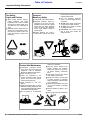
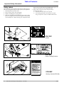
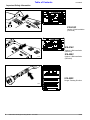
Table of Contents
Operator’s Manual
FDR15
Rear Discharge Grooming
Mowers
13600
Cover photo may show optional equipment not supplied with standard unit.
!
Read the Operator’s manual entirely. When you see this
symbol, the subsequent instructions and warnings are
serious - follow without exception. Your life and the lives
of others depend on it!
© Copyright 2000 Printed 5/01/08
310-188M
Land Pride
Table of Contents
Table of Contents
Important Safety Information . . . . . . . . . . .1
Safety Labels . . . . . . . . . . . . . . . . . . . . . . . . . . . 4
Section 4 Troubleshooting . . . . . . . . . . .13
Introduction . . . . . . . . . . . . . . . . . . . . . . . .8
Maintenance . . . . . . . . . . . . . . . . . . . . . . . . . . . . 14
Service Mowing Blades . . . . . . . . . . . . . . . . . . . . 14
Blade Sharpening . . . . . . . . . . . . . . . . . . . . . . 14
Blade Replacement . . . . . . . . . . . . . . . . . . . . . 14
V-Belt Installation . . . . . . . . . . . . . . . . . . . . . . 14
Storage . . . . . . . . . . . . . . . . . . . . . . . . . . . . . . . . 14
AIR TIRES (AIR PRESSURE): . . . . . . . . . . . . . . . 14
Lubrication . . . . . . . . . . . . . . . . . . . . . . . . . . . . . . 15
Driveline Shaft U-Joints . . . . . . . . . . . . . . . . . . 15
Wheel Support Bushings & Wheel Bearings . . 15
Bearing in Blade Spindle Hubs . . . . . . . . . . . . 15
Gearbox . . . . . . . . . . . . . . . . . . . . . . . . . . . . . 16
Driveline Profiles . . . . . . . . . . . . . . . . . . . . . . . 16
Using This Manual . . . . . . . . . . . . . . . . . . . . . . . . . 8
Terminology: . . . . . . . . . . . . . . . . . . . . . . . . . . . 8
Definitions: . . . . . . . . . . . . . . . . . . . . . . . . . . . . 8
Owner Assistance . . . . . . . . . . . . . . . . . . . . . . . . . 8
Section 1 Assembly and Setup . . . . . . . . .9
Tractor Requirements . . . . . . . . . . . . . . . . . . . . . . 9
Upper Hitch Arms . . . . . . . . . . . . . . . . . . . . . . . . . 9
Tractor Hook-Up . . . . . . . . . . . . . . . . . . . . . . . . . 10
Driveline Installation . . . . . . . . . . . . . . . . . . . . . . . 10
Section 2 Operating Instructions . . . . . .11
Transporting . . . . . . . . . . . . . . . . . . . . . . . . . . . . 11
Mowing Instructions . . . . . . . . . . . . . . . . . . . . . . . 11
Operating Instructions . . . . . . . . . . . . . . . . . . . . . 11
Section 3 Adjustments . . . . . . . . . . . . . . .12
Leveling the Mower . . . . . . . . . . . . . . . . . . . . . . . 12
Cutting Height Adjustment . . . . . . . . . . . . . . . . . . 12
3-Point Hitch Adjustments . . . . . . . . . . . . . . . . . . 12
Belt Tension . . . . . . . . . . . . . . . . . . . . . . . . . . . . . 12
Section 5 Maintenance and Lubrication .14
Section 6 Specifications and Capacities 17
Section 7 Appendix . . . . . . . . . . . . . . . . .18
Torque Values Chart for Common Bolt Sizes . . . . 18
Tire Inflation Chart . . . . . . . . . . . . . . . . . . . . . . . . 18
Warranty . . . . . . . . . . . . . . . . . . . . . . . . . . . . . . . 19
© Copyright 2000 All rights Reserved
Land Pride provides this publication “as is” without warranty of any kind, either expressed or implied. While every precaution has been taken in the preparation of this manual,
Land Pride assumes no responsibility for errors or omissions. Neither is any liability assumed for damages resulting from the use of the information contained herein. Land
Pride reserves the right to revise and improve its products as it sees fit. This publication describes the state of this product at the time of its publication, and may not reflect
the product in the future. The illustrations in this manual are not intended for safe and proper assembly or disassembly of equipment. The illustrations are intended for ordering parts only.
Land Pride is registered trademark.
All other brands and product names are trademarks or registered trademarks of their respective holders.
Printed in the United States of America.
FDR15 Rear Discharge Grooming Mowers 310-188M
5/8/08
Table of Contents
Land Pride
Important Safety Information
Important Safety Information
Be Aware of Signal Words
The word that designates a degree
or level of hazard seriousness. The
signal words are:
! DANGER!
Indicates an imminently hazardous
situation which, if not avoided, will
result in death or serious injury. This
signal word is limited to the most
extreme situations, typically for
machine components that, for functional purposes, cannot be guarded.
! WARNING!
Indicates a potentially hazardous situation which, if not avoided, could
result in death or serious injury, and
includes hazards that are exposed
when guards are removed. It may
also be used to alert against unsafe
practices.
! CAUTION!
Indicates a potentially hazardous situation which, if not avoided, may
result in minor or moderate injury. It
may also be used to alert against
unsafe practices.
Keep Riders
Off Machinery
▲ Riders obstruct the operator’s
view they could be struck by foreign objects or thrown from the
machine.
▲ Never allow children to operate
equipment.
!
For Your Protection
▲ Thoroughly read and understand
Shutdown and Storage
OFF
▲ Lower machine to ground, put
the “Safety Label” section, read all
instructions noted on them.
tractor in park, turn off engine,
and remove the key.
▲ Detach and store implements in a
area where children normally do
not play. Secure implement by
using blocks and supports.
ON
5/8/08
FDR15 Rear Discharge Grooming Mowers 310-188M
1
Table of Contents
Land Pride
Important Safety Information
Use Safety
Lights and Devices
Transport
Machinery Safely
▲ Slow moving tractors, self-pro-
▲ Comply with state and local laws.
▲ Maximum transport speed for
pelled equipment, and towed
implements can create a hazard
when driven on public roads. They
are difficult to see, especially at
night.
▲ Flashing warning lights and turn
signals are recommended whenever driving on public roads. Use
lights and devices provided with
implement.
implement is 20 mph. DO NOT
EXCEED. Never travel at a speed
which does not allow adequate
control of steering and stopping.
Some rough terrains require a
slower speed.
▲ Sudden breaking can cause a
towed load to swerve and upset.
Practice Safe Maintenance
▲ Understand
procedure before
doing work. Use proper tools and
equipment, refer to Operator’s
Manual for additional information.
▲ Work in a clean dry area.
▲ Lower the implement to the
ground, put tractor in park, turn off
engine, and remove key before
preforming maintenance.
▲ Allow implement to cool completely.
▲ Install all transport locks on raised
drill before working underneath, refer
to the Operator’s Manual for quantity
and location of transport locks.
▲ Do not grease or oil implement
2
FDR15 Rear Discharge Grooming Mowers 310-188M
Reduce speed if towed load is not
equipped with breaks.
▲ Use the following maximum
speed - tow load weight ratios as
a guideline:
▲ 20 mph when weight is less than
or equal to the weight of tractor.
▲ 10 mph when weight is double
the weight of tractor.
▲ IMPORTANT: Do not tow a load
that is more than double the
weight of tractor.
while it is in operation.
▲ Move the opener handle to the
“ROAD” position and complete
raising the openers to lock them
up before working underneath
them.
▲ Disk edges are sharp. Be careful
when working in this area.
▲ Disconnect battery ground cable
(-) before servicing or adjusting
electrical systems or before welding on implement.
▲ Inspect all parts. Make sure parts
are in good condition & installed
properly.
▲ Remove buildup of grease, oil or
debris.
▲ Remove all tools and unused pars
5/8/08
Table of Contents
Land Pride
Important Safety Information
Prepare for Emergencies
▲ Be prepared if a fire starts.
▲ Keep a first aid kit and fire extinguisher handy.
▲ Keep emergency numbers for
doctor, ambulance, hospital and
fire department near phone.
Wear
Protective Equipment
▲ Protective clothing and equipment
should be worn.
▲ Wear clothing and equipment
appropriate for the job. Avoid
loose fitting clothing.
▲ Prolonged exposure to loud noise
can cause hearing impairment or
hearing loss. Wear suitable hearing protection such as earmuffs or
earplugs.
▲ Operating
equipment
safely
requires the full attention of the
operator. Avoid wearing radio
headphones
while
operating
machinery.
Tire Safety
▲ Tire changing can be dangerous
and should be preformed by
trained personnel using the correct tools and equipment.
▲ When inflating tires, use a clip-on
chuck and extension hose long
enough to allow you to stand to
one side and NOT in front of or
over the tire assembly. Use a
safety cage if available.
▲ When removing and installing
wheels, use wheel handling
equipment adequate for the
weight involved.
911
Safety at All Times
Thoroughly read and understand the
instructions given in this manual
before operation. Refer to the “Safety
Label” section, read all instructions
noted on them.
▲ Operator should be familiar with
all functions of the unit.
▲ Operate implement from the
driver’s seat only.
▲ Do not leave tractor or implement
unattended with engine running.
▲ Dismounting from a moving trac-
5/8/08
tor could cause serious injury or
death.
▲ Do not stand between the tractor
and implement during hitching.
▲ Keep hands, feet, and clothing
away from power-driven parts.
▲ Wear snug fitting clothing to avoid
entanglement with moving parts.
▲ Watch out for wires, trees, etc.,
when folding and raising implement. Make sure all persons are
clear of working area.
▲ Turning tractor too tight may
cause implement to ride up on
wheels. This could result in injury
FDR15 Rear Discharge Grooming Mowers 310-188M
3
Table of Contents
Land Pride
Important Safety Information
Safety Labels
Your implement comes equipped with all safety labels in place.
They were designed to help you safely operate your implement.
1. Read and follow label directions.
2. Keep all safety labels clean and legible.
3. Replace all damaged or missing labels.
4. Some new equipment installed during repair require safety
labels to be affixed to the replaced component as specified
by the manufacturer. When ordering new components make
sure the correct safety labels are included in the request. To
order new labels go to your Land Pride dealer.
5. Refer to this section for proper label placement.
To install new labels:
a. Clean the area the label is to be placed.
b. Peel backing from label. Press firmly on surface
being careful not to cause air bubbles under label.
818-130C
Caution
13304
818-142C
13307
Danger: Rotating Driveline
818-554C
13306
4
FDR15 Rear Discharge Grooming Mowers 310-188M
Warning: General (FDR1548)
5/8/08
Land Pride
Table of Contents
Important Safety Information
818-554C
13721
Warning: General (FDR1560)
818-554C
13716
Warning: General (FDR1572)
818-555C
13850
13850
5/8/08
Danger: Rotating Blade
818-556C
Danger: Thrown Object
FDR15 Rear Discharge Grooming Mowers 310-188M
5
Table of Contents
Land Pride
Important Safety Information
818-293C
13310
Caution: V-Belt Installation
(FDR1548)
818-514C
Caution: V-Belt Installation
(FDR1572)
818-529C
13719
Caution: V-Belt Installation
(FDR1560)
ROTATING DRIVELINE
KEEP AWAY!
818-552C
Danger: Rotating Driveline
13314
6
FDR15 Rear Discharge Grooming Mowers 310-188M
5/8/08
Land Pride
Table of Contents
Important Safety Information
13314
13711
5/8/08
818-540C
Danger: Guard Missing
818-230C
Red Reflector
FDR15 Rear Discharge Grooming Mowers 310-188M
7
Table of Contents
Land Pride
Introduction
Introduction
Land Pride welcomes you to the growing family of new
product owners.
This implement has been designed with care and built by
skilled workers using quality materials. Proper assembly,
maintenance, and safe operating practices will help you
get years of satisfactory use from the machine.
Serial Number Plate
Refer to the Figure 1 for the location of your serial number
plate.
The parts on your FDR15 Grooming Mower have been
specially designed and should only be replaced with genuine Land Pride parts. Therefore, should your Rotary Cutter require replacement parts go to your Land Pride
Dealer.
Using This Manual
This Operator’s Section is designed to help familiarize you
with safety, assembly, operation, adjustments, troubleshooting, and maintenance. Read this manual and follow
the recommendations to help ensure safe and efficient
operation.
The warranty Registration card should be filled out by the
dealer at the time of purchase.
To order a new Operator or Parts Manual contact your authorized dealer. You may obtain parts information from our
website at www.landpride.com.
The information contained within this manual was current
at the time of printing. Some parts may change slightly to
assure you of the best performance.
Terminology:
"Right " or "Left" as used in this manual is determined by
facing the direction the machine will travel while in use unless otherwise stated.
Definitions:
IMPORTANT: A special point of information related to
its preceding topic. The author’s intention is that this information should be read and noted before continuing.
NOTE: A special point of information that the author feels
an operator must be aware of before continuing.
Owner Assistance
If customer service or repair parts are required contact an
Land Pride dealer. A dealer has trained personnel, repair
parts and equipment needed to service the implement.
Serial Number Plate Location
Figure 1
15030
For prompt service always use the serial number and model
number when ordering parts from your Land Pride dealer.
Be sure to include your serial and model numbers in correspondence also.
Your dealer wants you to be satisfied with your new machine. If for any reason you do not understand any part of
this manual or are not satisfied with the service received,
the following actions are suggested:
1. Discuss the matter with your dealership service manager make sure he is aware of any problems you may
have and that he has had the opportunity to assist you.
2. If you are still not satisfied, seek out the owner or general manager of the dealership, explain the problem
and request assistance.
3. For further assistance write to:
Product Support
Land Pride, Service Department
1525 East North Street
P.O. Box 5060
Salina, Ks. 67402-5060
These parts have been specially designed and should
only be replaced with genuine Land Pride parts.
8
FDR15 Rear Discharge Grooming Mowers 310-188M
5/8/08
Table of Contents
Land Pride
Section 1 Assembly and Setup
Section 1 Assembly and Setup
Tractor Requirements
Upper Hitch Arms
This mower is designed with a 3-Point category I hitch.
Horse power rating of tractor should not exceed 26 PTO
horse power for FDR1548 mowers and 35 PTO for
FDR1560 & FDR1572 mowers.
Refer to Figure 1-1:
1. Remove the upper hitch bars (#1), upper hitch braces
(#2), and upper pivoting hitch subassembly (#3) from
the storage position on top of the mower deck.
2. Bolt the upper hitch braces to the mounting tabs on
back of the deck using 1/2" bolts (#4), lock washer
(#5), and hex nut (#6).
3. Mount the upper hitch bars (#1), to the inside of front
hitch plates on the mower frame using the 5/8" x 1 3/
4" long bolts (#7), lock washers (#8) and hex nuts (#9).
4. Remove 5/8" x 5" long bolt (#10), lock washer (#8),
and hex nut (#9) from the upper pivoting hitch subassembly.
5. Swing the upper hitch bars (#1) up to a vertical position. Raise the upper hitch braces (#2) up inside the
upper hitch bars as shown.
6. Assemble upper pivoting hitch (#3), spacer top hitch
(#11), 5/8" x 5" long bolt (#10), lock washer (#12), and
hex nut (#13) as shown.
NOTE: In order to maintain steering control, ballast
may need to be added to your tractor. To determine
whether or not to add the ballast, refer to your tractors’ operator manual.
FDR1548
FDR1560 & FDR1572
15028
Upper Hitch Arms Assembly
Figure 1-1
5/8/08
FDR15 Rear Discharge Grooming Mowers 310-188M
9
Table of Contents
Land Pride
Section 1 Assembly and Setup
Tractor Hook-Up
Driveline Installation
1. Be certain that tractor draw bar will not interfere. Move
draw bar ahead or remove if required. Draw bar
should also be checked for clearance when unit is being raised for the first time.
2. Align lower link arms of tractor to hitch clevises on
mower. Insert lower hitch pins into lower ball swivels
and attach lynch pins.
3. Attach tractor top link to upper floating hitch on mower
with pin supplied. Secure with lock pin Refer to Figure
1-2.
4. Adjust the tractor top link in or out to place the upper
hitch pin vertically above the lower hitch pins as
shown in Figure 1-2, to allow mower flotation.
1. Slide driveline end with extended safety cone over
splined shaft of the gearbox and secure with attaching
device.
2. Slide driveline over the tractor’s splined PTO shaft
and secure with locking device of powershaft.
3. Driveline should now be moved back and forth to insure that it is secure on the PTO shaft of the tractor
and mower gearbox.
4. Attach the chain from the PTO shield to one of the upper hitch braces to ensure that the shield does not rotate.
5. Should the driveline require shortening:
a. Hold the half-shafts next to each other in the
shortest working position and mark them.
b. Shorten inner and outer guard tubes equally.
c. Shorten inner and outer sliding profiles by the
same length as the guard tubes.
d. Proper overlap is a minimum of one-half the
length of each tube, with both tubes being of equal
length.
e. Round off all sharp edges and remove burrs.
Grease sliding profiles.
Tractor Hook-Up
Figure 1-2
10
FDR15 Rear Discharge Grooming Mowers 310-188M
13816
!
CAUTION!
Tractor PTO shield and all mower guards must be in place at
all times during operation!
5/8/08
Land Pride
Table of Contents
Section 2 Operating Instructions
Section 2 Operating Instructions
Transporting
NOTE: Always disengage PTO before raising the
mower to transport position.
2. When raising the mower to the transport position, be
sure that powershaft does not contact tractor or mower. Adjust and set the tractor’s 3-point hitch lift height
so that the PTO shaft does not contact mower deck, in
the fully raised position.
3. Be sure to reduce tractor ground speed when turning;
and, leave enough clearance so the mower does not
contact obstacles such as buildings, trees
or fences.
4. Select a safe ground travel speed when transporting
from one area to another. When traveling on roadways, transport in such a way that faster moving vehicles may pass you safely.
5. When traveling over rough or hilly terrain, shift tractor
to a lower gear.
!
CAUTION!
When traveling on public roads, whether at night or during the
day, use accessory lights and devices for adequate warning to
operators of other vehicles. Comply with all Federal, State, and
local laws.‘
Mowing Instructions
6. Clear the area to be mowed of objects and debris that
might be picked up and thrown by the mower blades.
7. Grass is best cut when it is dry. Mowing wet grass can
cause plugging resulting in grass clumps behind the
mower.
8. Grass should be mowed frequently as shorter clippings deteriorate faster.
9. If mowing extremely tall grass, it is best to raise cutting
height and mow the area, then lower cutting height
and mow a second time at the desired height.
5/8/08
!
CAUTION!
When mowing in sandy soil areas, wear may occur to your
mower blades caused from sand erosion. Frequent inspection
should be made and blades replaced if damaged.
Operating Instructions
Proper Servicing and adjustments is the key to the long life
of any machine. With careful and systematic inspection of
the mower, you can avoid costly maintenance, time and
repair.
Before beginning to mow, the following inspection should
be performed:
1. Check oil level in gearbox. Refer to "Section 5 Maintenance and Lubrication”starting on page 14.
2. Check that all plugs in gearbox have been replaced
and tightened properly.
3. Be sure all mower blades, bolts and nuts are tight.
4. Be certain all guards and shields are in place and secure.
5. Grease PTO shaft and all other grease fittings.
6. Clear the area to be mowed of rocks, branches and
other foreign objects.
7. Lower mower to ground. Set tractor throttle at approximately 1/4 open. Engage PTO to start blades rotating.
8. Operate with 540 rpm PTO tractor.
9. At first begin mowing at a slow forward speed and shift
up until the desired speed is achieved - maintaining
540 PTO rpm.
10. Mower blades will cut better at a faster blade speed
than at reduced throttle.
11. After mowing the first 50 feet, stop and check to see
that the mower is adjusted properly.
12. Do not make sharp turns or attempt to back up while
mower is on the ground.
13. Do not engage PTO with mower in the fully raised position. Do not engage PTO at full throttle.
FDR15 Rear Discharge Grooming Mowers 310-188M
11
Table of Contents
Land Pride
Section 3 Adjustments
Section 3 Adjustments
Leveling the Mower
3-Point Hitch Adjustments
The 3-point hitch system on this mower has been designed for front to back flotation when mowing on uneven
terrain. Adjust the tractor’s top link to place the upper hitch
pin vertically above the lower hitch pins as shown below.
NOTE: Tractor and mower should be on level
ground.
14. Set lower hitches and upper floating hitch, as shown
below in Figure 3-1.
15. Start tractor and raise mower, watching that tractor
draw bar (if not removed) does not interfere with mower.
16. Slowly lower the mower until gauge wheels touch the
ground and the lower mower 3-point hitch bars are
parallel to the ground in floating position. Set tractor 3point stop.
17. Set park brake and turn off tractor. Remove key from
ignition.
18. Rotate blades parallel to direction of travel.
19. Measure the clearance from the cutting edge to the
ground at front and rear of the blade. This measurement should be equal or have the blade at the front of
the mower not more than 1/2" lower than the blade at
the rear of the mower.
!
CAUTION!
Engage parking brake, shut off tractor, remove key and disengage PTO before making any height adjustments!
Belt Tension
Refer to Figure 3-2:
!
CAUTION!
Belt drive system under spring tension; use care to avoid bodily
harm!
1. To check tension apply force at arrow A. With a tension tester and deflect the belt 1/4". The force required
to get this deflection should range from 7 to 10 lbs.
2. To adjust belt tension, adjust eyebolt (#1), as necessary. This adjustment will increase or decrease the
tension on spring (#2).
3. Excessive tension on the belt may lead to premature
failure of belt and drive components. Excessive tension on the belt may also lead to a safety hazard to the
operator or bystanders. Not enough tension on the
belt may lead to premature failure of the belt due to excessive slipping.
!
WARNING!
Excessive tension on the belt may lead to premature failure of
belt and drive components. Excessive tension on the belt may
also lead to a safety hazard to the operator or bystanders.
13816
3-Point Hitch
Figure 3-1
Cutting Height Adjustment
1. Using the tractor, raise the mower off the ground and
support under it with secure blocking so not to let the
mower drift down during maintenance.
2. Holding wheel and yoke assembly up, remove quicklock pin from top of gauge wheel spindle. Position full
length spacers and half spacer as required. All spacers on top of spindle tube allows for approximately 3/
4" cutting height. Adjustments range from 3/4" to a
maximum of 3-1/4" in 1/2" increments on FDR1548
mowers and 5 1/4” in 1/2” increments on FDR1560 &
FDR1572 mowers. Refer to “Leveling the Mower”
beginning on this page.
12
FDR15 Rear Discharge Grooming Mowers 310-188M
Belt Tension
Figure 3-2
13663
5/8/08
Land Pride
Table of Contents
Section 4 Troubleshooting
Section 4 Troubleshooting
Problem
Solution
Discharge chute plugged
Check installation of belt.
Wait until grass dries.
Raise cutting height of mower and cut grass twice.
Mow at full throttle (540 PTO rpm), check PTO speed and tractor engine.
Shift transmission to a lower gear.
!
CAUTION!
Do not try to clean discharge chute when mower is running. Bodily harm may occur!
Belt slipping
Unplug and clean mower deck.
Remove belt guard shields and clean sheaves.
Tighten spring take-up eyebolt.
Replace belt.
Patches of uncut grass
Mow at full throttle (540 PTO rpm), check PTO speed and tractor engine.
Shift transmission to a lower gear.
Tighten spring take-up eyebolt.
Sharpen and balance or replace blade.
Excessive vibration
Remove belt guard shield and clean debris from belt area and sheaves.
Replace drive belt.
Replace sheaves or align.
Remove belt guard shields & clean debris from belt area & sheaves.
Readjust 3-point hitch to raise mower to maximum of 14 inches.
Gearbox noisy
Check lubricant level.
Blades scalping grass
Raise cutting height by adjusting wheels.
Change mowing pattern.
Reduce speed turns.
Uneven cut
Shift to a lower gear.
Level mower.
Sharpen blades & balance or replace.
Tractor loaded down by mower
Mow at full throttle (540 PTO rpm).
Shift to a lower gear.
Clean mower.
5/8/08
FDR15 Rear Discharge Grooming Mowers 310-188M
13
Table of Contents
Land Pride
Section 5 Maintenance and Lubrication
Section 5 Maintenance and Lubrication
Maintenance
Proper servicing and adjustment is the key to the long life
of any implement. With careful and systematic inspection,
you can avoid costly maintenance, time and repair.
After using the unit for several hours, check all bolts to be
sure they are tight.
Replace any worn, damaged or illegible safety labels by
obtaining new labels from your Land Pride Dealer.
!
CAUTION!
For safety reasons, each maintenance operation must be performed with tractor PTO disengaged, the mower lowered completely to the ground or folded with the transport locks engaged
and the tractor engine shut off with ignition key removed.
• After using the mower for several hours, check all bolts
to be sure they are tight and check the tension of the
drive belt. Refer to Belt Tension in the “Adjustments”
section on page 12.
• Lubricate items as listed under Lubrication, this section,
starting on page 15.
• Always maintain the proper air pressure in the tires. The
Tire Inflation Chart is located in the “Appendix” section
on page 18.
• Replace any worn, damaged or illegible safety labels by obtaining new labels from your Land Pride Dealer. Information
about labels is located under Safety Labels in the “Important Safety Information” section starting on page 1.
Service Mowing Blades
Blade Sharpening
Blades should be sharpened at each end to the same angle as the original cutting edge.
NOTE: Care should be taken in order not to remove
any more material than necessary to sharpen blade.
Balance each blade after sharpening.
Blade Replacement
IMPORTANT: Always install blade with the cutting edge
facing direction of rotation. Refer to Figure 3-2 on page 12
for proper blade placement due to different rotations on
decks.
1. Remove the bolt and blade washer from the bottom of
the blade to be replaced. Remove blade.
2. Install the blade washer into the center hole on blade.
14
FDR15 Rear Discharge Grooming Mowers 310-188M
3. Replace the bolt. Tighten to the proper torque as listed
in the Torque Values Chart in the “Appendix” section
on page 18.
IMPORTANT: Replace blades with Land Pride blades only.
V-Belt Installation
These illustrations are also on the labels located on the
top of the mower decks.
1. Remove the right hand and the left hand belt covers.
2. Disengage belt tensioning latch by turning release nut
with a 3/4" socket or wrench.
3. With tension relieved from belt remove old belt from
pulleys.
4. To install a new belt be sure the belt is positioned in all
the pulley grooves. Engage belt tensioning latch by
turning release nut with a 3/4" socket or wrench to apply tension to new belt. Check the belt tension, refer to
Figure 3-2 on page 12.
5. Reinstall all belt covers and secure in place with hardware.
Storage
At the end of the working season or when the mower will
not be used for a long period, it is good practice to clean off
any dirt or grease that may have accumulated on the
mower and any of the moving parts.
1. Clean as necessary.
2. Check the blades for wear and replace if necessary,
see Service Mowing Blades, this section on page 14.
3. Inspect the mower for loose, damaged or worn parts
and adjust or replace as needed.
4. Lubricate as noted in the Lubrication portion of this
section starting on page 15.
5. Store unit inside if possible for longer life.
Repaint parts where paint is worn or scratched to prevent
rust. Ask your dealer for Aerosol Land Pride Beige touchup paint #821-011C.
AIR TIRES (AIR PRESSURE):
Tire Sealant: Heavy Duty tire sealant has been added in
Air tires to help reduce air loss from punchers due to nails/
thorns etc....
NOTE: Under inflated tires can roll off of rim. Maintaining air pressure within 5 PSI of maximum tire pressure
reduces the risk of tires rolling off of rim.
5/8/08
Table of Contents
Land Pride
Section 5 Maintenance and Lubrication
Lubrication
Lubrication
Legend
Multipurpose
spray lube
Multipurpose
grease lube
Multipurpose
oil lube
50
Intervals at which
lubrication is required
25
Driveline Shaft U-Joints
Type of Lubrication: Multipurpose Grease
13545
25
Wheel Support Bushings & Wheel Bearings
Type of Lubrication: Multipurpose Grease
13717
25
Bearing in Blade Spindle Hubs
Type of Lubrication: Multipurpose Grease
13600
5/8/08
FDR15 Rear Discharge Grooming Mowers 310-188M
15
Table of Contents
Land Pride
Section 5 Maintenance and Lubrication
As
Required
DO NOT
OVERFILL!
Gearbox
Type of Lubrication: SAE 90W Gear Lube
Check the oil level in the gearbox by removing the plug in the
top of the box. Add oil if necessary into the biggest plug at
the back of the box. Retighten both plugs.
Do not overfill! Should your gearbox require service, take it to
your LAND PRIDE dealer.
16648
IMPORTANT: Mower should be level when checking oil in
gearbox!
Inner
Tube
20
Driveline Profiles
Type of Lubrication: Multipurpose Grease
13648
16
FDR15 Rear Discharge Grooming Mowers 310-188M
5/8/08
Table of Contents
Land Pride
Section 6 Specifications and Capacities
Section 6 Specifications and Capacities
FDR1548, FDR1560 and FDR1572 Rear Discharge Grooming Mowers
FDR1548
FDR1572
Cutting Width
48"
60"
72"
Overall Width
51"
62"
74"
Height
36"
Length
51”
61”
Weight
325#
492#
Cutting Height
Blades-3
1/4” x 2 1/2” x 16-3/4” Heat
Treated Alloy Steel
16,260 FPM
1/4” x 2 1/2” x 20 3/4” Heat
Treated Alloy Steel
1/4” x 2 1/2” x 25” Heat
Treated Alloy Steel
18,264 FPM
18,340 FPM
Greasable
Hitch
Category l Floating Clevis
Castered 8” x 3” Air Tire
Caster Wheel Spindle
Castered 10” x 4” Air Tire
1” Diameter with Greasable Bushing
Drive Train
Recommended Tractor PTO HP
594#
3/4” - 5 1/4” (1/2” increments)
1 1/4”
Blade Spindles
Gauge Wheels
64”
10 Gauge
Blade Overlap
Blade Tip Speed
36" to 39 1/2”
3/4” - 3 1/4” (1/2” increments)
Deck Material Thickness
5/8/08
FDR1560
540 RPM PTO
Gearbox
1:2.83 Ratio
Cast Iron Housing
Spring Loaded Single V-Belt
26 Maximum
35 Maximum
FDR15 Rear Discharge Grooming Mowers 310-188M
17
Table of Contents
Land Pride
Section 7 Appendix
Section 7 Appendix
Torque Values Chart for Common Bolt Sizes
Bolt Head Identification
Bolt Size
(Inches)
in-tpi1
Grade 2
Grade 5
Bolt Head Identification
5.8
Bolt Size
(Metric)
Grade 8
N · m2
ft-lb3
N·m
ft-lb
N·m
ft-lb
mm x pitch4
1/4" - 20
7.4
5.6
11
8
16
12
1/4" - 28
8.5
6
13
10
18
8.8
Class 5.8
10.9
Class 8.8
Class 10.9
N·m
ft-lb
N·m
ft-lb
N·m
M 5 X 0.8
4
3
6
5
9
ft-lb
7
14
M6X1
7
5
11
8
15
11
5/16 - 18
15
11
24
17
33
25
M 8 X 1.25
17
12
26
19
36
27
5/16" - 24
17
13
26
19
37
27
M8X1
18
13
28
21
39
29
3/8" - 16
27
20
42
31
59
44
M10 X 1.5
33
24
52
39
72
53
3/8" - 24
31
22
47
35
67
49
M10 X 0.75
39
29
61
45
85
62
7/16" - 14
43
32
67
49
95
70
M12 X 1.75
58
42
91
67
125
93
7/16" - 20
49
36
75
55
105
78
M12 X 1.5
60
44
95
70
130
97
1/2" - 13
66
49
105
76
145
105
M12 X 1
90
66
105
77
145
105
1/2" - 20
75
55
115
85
165
120
M14 X 2
92
68
145
105
200
150
9/16" - 12
95
70
150
110
210
155
M14 X 1.5
99
73
155
115
215
160
9/16" - 18
105
79
165
120
235
170
M16 X 2
145
105
225
165
315
230
5/8" - 11
130
97
205
150
285
210
M16 X 1.5
155
115
240
180
335
245
5/8" - 18
150
110
230
170
325
240
M18 X 2.5
195
145
310
230
405
300
3/4" - 10
235
170
360
265
510
375
M18 X 1.5
220
165
350
260
485
355
3/4" - 16
260
190
405
295
570
420
M20 X 2.5
280
205
440
325
610
450
7/8" - 9
225
165
585
430
820
605
M20 X 1.5
310
230
650
480
900
665
7/8" - 14
250
185
640
475
905
670
M24 X 3
480
355
760
560
1050
780
1" - 8
340
250
875
645
1230
910
M24 X 2
525
390
830
610
1150
845
1" - 12
370
275
955
705
1350
995
M30 X 3.5
960
705
1510
1120
2100
1550
1710
1-1/8" - 7
480
355
1080
795
1750
1290
M30 X 2
1060
785
1680
1240
2320
1 1/8" - 12
540
395
1210
890
1960
1440
M36 X 3.5
1730
1270
2650
1950
3660
2700
1 1/4" - 7
680
500
1520
1120
2460
1820
M36 X 2
1880
1380
2960
2190
4100
3220
1 1/4" - 12
750
555
1680
1240
2730
2010
1 3/8" - 6
890
655
1990
1470
3230
2380
1
in-tpi = nominal thread dia .in inches-threads per inch
1 3/8" - 12
1010
745
2270
1670
3680
2710
2
N· m = newton-meters
ft-lb= foot pounds
1 1/2" - 6
1180
870
2640
1950
4290
3160
3
1 1/2" - 12
1330
980
2970
2190
4820
3560
4 mm
x pitch = nominal thread dia. in millimeters x thread pitch
Torque tolerance + 0%, -15% of torquing values. Unless otherwise specified use torque values listed above.
Tire Inflation Chart
Tire Size
18
Inflation PSI
8” x 3” Air Tire
30
10” x 4” Air Tire
50
FDR15 Rear Discharge Grooming Mowers 310-188M
5/8/08
Warranty
Land Pride warrants to the original purchaser that this Land Pride product will
be free from defects in material and workmanship for a period of one year, from
the date of purchase by the end user, when used as intended and under normal
service and conditions for personal use. This Warranty is limited to the replacement of any defective part by Land Pride and the installation by the dealer of any
such replacement part, and does not cover common wear items such as blades,
belts, tines, etc. Land Pride reserves the right to inspect any equipment or parts
which are claimed to have been defective in material or workmanship.
This Warranty does not apply to any part or product which in Land Pride’s judgment shall have been misused or damaged by accident or lack of normal maintenance or care, or which has been repaired or altered in a way which adversely
affects its performance or reliability, or which has been used for a purpose for
which the product is not designed. Misuse also specifically includes failure to properly maintain oil levels, grease points, and driveline shafts.
Claims under this Warranty must be made to the dealer which originally sold
the product and all warranty adjustments must be made through such dealer. Land
Pride reserves the right to make changes in materials or design of the product at
any time without notice.
This Warranty shall not be interpreted to render Land Pride liable for damages
of any kind, direct, consequential, or contingent to property. Furthermore, Land
Pride shall not be liable for damages resulting from any cause beyond its reasonable control. This Warranty does not extend to loss of crops, any expense or loss
for labor, supplies, rental machinery or for any other reason.
No other warranty of any kind whatsoever, express or implied, is made
with respect to this sale; and all implied warranties of merchantability and
fitness for a particular purpose which exceed the obligations set forth in this
written warranty are hereby disclaimed and excluded from this sale.
This Warranty is not valid unless registered with Land Pride within 30 days from
the date of purchase by the end user.
In addition to the Standard Limited Warranty Land Pride also provides:
A Five - Year Limited Warranty on Gearbox Components, on RC6015,
RCM6015, RC5015, RCM5015, RC5010, RCM5010, PD15, PD25, PD35 and
RCR3515, RCRM3515 Divider Boxes. A Three - Year Limited Warranty on Gearbox Components on RCR3596, RCR3510, RCRM3510 and RCR3515,
RCRM3515 wing Gear Boxes, provided they have been properly maintained, and
not subjected to misuse or abuse. Misuse specifically includes, but is not limited
to, maintaining proper oil levels of the correct lubricant, and adjusting slip-clutches
to provide proper protection to Gearbox Components. Warranty is One Year for
seals. Seals are viewed as normal wear items and replacement will be the customer’s responsibility. Gearboxes will either be replaced or rebuilt at Land Pride’s
discretion.
Corporate Office: P.O. Box 5060
Salina, Kansas 67402-5060 USA