1
Table of Contents
Operator’s Manual
RC15, RC25, and RC35 Series
Rotary Cutter
Manufacturing, Inc.
P.O. Box 5060 ● Salina, Kansas 67402-5060
!
Model RC15
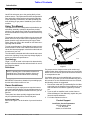
Read the Operator’s manual entirely. When you see this symbol, the subsequent instructions and warnings are serious - follow without exception. Your life and the lives of others
depend on it!
Model RC25
14484
Model RC35
14489
14490
Cover illustration may show optional equipment not supplied with standard unit.
© Copyright 2008 Printed 9/25/08
312-298M
Land Pride
Table of Contents
Table of Contents
Important Safety Information . . . . . . . . . . .1
Section 5 Maintenance and Lubrication .17
Introduction . . . . . . . . . . . . . . . . . . . . . . . .8
Maintenance . . . . . . . . . . . . . . . . . . . . . . . . . . . . 17
Service Cutting Blades . . . . . . . . . . . . . . . . . . . . . 17
Shearbolt Driveline . . . . . . . . . . . . . . . . . . . . . . . . 17
Walterscheid Slip Clutch Run-In . . . . . . . . . . . . . . 17
Eurocardan Clutch Run-In . . . . . . . . . . . . . . . . . . 17
Eurocardan Clutch Assembly & Disassembly . . . . 18
Storage . . . . . . . . . . . . . . . . . . . . . . . . . . . . . . . . 18
4-Plate Slip Clutch . . . . . . . . . . . . . . . . . . . . . . . . 19
Disassembly . . . . . . . . . . . . . . . . . . . . . . . . . . 19
Assembly . . . . . . . . . . . . . . . . . . . . . . . . . . . . . 19
2-Plate Slip Clutch . . . . . . . . . . . . . . . . . . . . . . . . 20
Disassembly . . . . . . . . . . . . . . . . . . . . . . . . . . 20
Assembly . . . . . . . . . . . . . . . . . . . . . . . . . . . . . 20
Lubrication . . . . . . . . . . . . . . . . . . . . . . . . . . . . . . 21
Tailwheel Spindle Hub . . . . . . . . . . . . . . . . . . . 21
Tailwheel hub . . . . . . . . . . . . . . . . . . . . . . . . . 21
Driveline U-Joints . . . . . . . . . . . . . . . . . . . . . . 21
Gearbox . . . . . . . . . . . . . . . . . . . . . . . . . . . . . 22
Driveline . . . . . . . . . . . . . . . . . . . . . . . . . . . . . 22
Using This Manual . . . . . . . . . . . . . . . . . . . . . . . . . 8
Terminology: . . . . . . . . . . . . . . . . . . . . . . . . . . . 8
Definitions: . . . . . . . . . . . . . . . . . . . . . . . . . . . . 8
Owner Assistance . . . . . . . . . . . . . . . . . . . . . . . . . 8
Section 1 Assembly and Setup . . . . . . . . .9
Tractor Requirements . . . . . . . . . . . . . . . . . . . . . . 9
Hitch Assembly . . . . . . . . . . . . . . . . . . . . . . . . . . . 9
RC15 Tailwheel . . . . . . . . . . . . . . . . . . . . . . . . . . 10
RC25 & RC35 Tailwheel . . . . . . . . . . . . . . . . . . . 10
Driveline Installation . . . . . . . . . . . . . . . . . . . . . . . 10
3-Point Tractor Hookup . . . . . . . . . . . . . . . . . . . . 10
Safety Guards . . . . . . . . . . . . . . . . . . . . . . . . . . . 11
Section 2 Operating Instructions . . . . . .12
Transporting . . . . . . . . . . . . . . . . . . . . . . . . . . . . 12
Operating Check List . . . . . . . . . . . . . . . . . . . . . . 12
Cutting Instructions . . . . . . . . . . . . . . . . . . . . . . . 12
Section 3 Adjustments . . . . . . . . . . . . . . .13
Cutting Height . . . . . . . . . . . . . . . . . . . . . . . . . . . 13
Section 4 Troubleshooting . . . . . . . . . . .15
Section 6 Specifications and Capacities 23
Section 7 Appendix . . . . . . . . . . . . . . . . .26
Torque Values Chart for Common Bolt Sizes . . . . 26
Warranty . . . . . . . . . . . . . . . . . . . . . . . . . . . . . . . 27
© Copyright 2008 All rights Reserved
Land Pride provides this publication “as is” without warranty of any kind, either expressed or implied. While every precaution has been taken in the preparation of this manual,
Land Pride assumes no responsibility for errors or omissions. Neither is any liability assumed for damages resulting from the use of the information contained herein. Land
Pride reserves the right to revise and improve its products as it sees fit. This publication describes the state of this product at the time of its publication, and may not reflect
the product in the future. The illustrations in this manual are not intended for safe and proper assembly or disassembly of equipment. The illustrations are intended for ordering parts only.
Land Pride is registered trademark.
All other brands and product names are trademarks or registered trademarks of their respective holders.
Printed in the United States of America.
RC15, RC25, and RC35 Series Rotary Cutter 312-298M
9/25/08
Table of Contents
Land Pride
Important Safety Information
Important Safety Information
For your safety and to develop a better understanding of
your equipment, thoroughly read the Operator’s Sections
of this manual before operation.
Safety Notations
!
The SAFETY ALERT SYMBOL indicates that there is a
potential hazard to personal safety involved and extra
safety precautions must be taken. When you see this symbol, be alert and carefully read the message that follows it.
In addition to design and configuration of equipment; hazard control and accident prevention are dependent upon
the awareness, concern, prudence and proper training of
personnel involved in the operation, transport, maintenance and storage of equipment.
Watch for the following Safety Notations throughout
your Operator’s Manual:
avoided, will result in death or serious injury. This signal word
is limited to the most extreme situations.
WARNING!
Indicates a potentially hazardous situation which, if not avoided, could result in death or serious injury.
!
CAUTION!
Indicates a potentially hazardous situation which, if not avoided, may result in minor or moderate injury. It may also be used
to alert against unsafe practices
Safety Rules
These rules and instructions
must be reviewed at least annually
by all operators!
Most accidents are the result of negligence and carelessness, caused by failure of the operator to follow safety precautions. Even though your implement is designed with
many built-in safety features, the following precautions are
mandatory to prevent such accidents.
Make sure everyone that uses this machine has read the
Operator’s Manual and understands how to operate it
safely.
9/25/08
Prior To Operation
1. Do not allow anyone to operate this machine who has not
been properly trained in its safe operation.
2. Wear proper eye protection to prevent injury from
flying objects.
3. To prevent personal injury caused by thrown objects,
the use of front safety shields is strongly recommended.
4. Do not let children operate the implement.
5. Never allow passengers.
6. Do not leave the tractor or the implement unattended with
the engine running.
7. Before cutting, clear the area of objects and debris that
could become entangled in the blades or thrown from the
cutter.
!
! DANGER!
Indicates an imminently hazardous situation which, if not
!
This Operator’s Manual is considered a part of the implement and should remain so when loaned or sold.
During Operation
1. Never operate the cutter near people and do not stand near
the cutter while blades are in motion.
2. After striking an object, disengage PTO, shut off tractor and
inspect for damage before continuing.
3. Do not operate the cutter in reverse unless necessary. Debris may be thrown from the front of the cutter; therefore, increasing the risk of injury to the operator.
4. Check the cutter periodically for loose hardware and tighten
if necessary.
5. Never operate the cutter while in the raised transport position.
6. Disengage the PTO when raised for transport or backing
up.
7. Travel slowly over rough terrain and be alert to holes and
gullies.
8. Use warning flags or approved warning lights at night and
during other periods of poor visibility. Do your best to prevent highway accidents.
9. Be alert to traffic when crossing or cutting near roadways.
Always maintain complete control of the machine. Know
your state and local laws concerning highway safety and
regulations. Comply with these laws when transporting machinery.
10. Keep PTO shielding in place and in good condition. Do not
operate cutter with shields missing.
11. Always use proper PTO speed or machine damage may result. This cutter is designed to be used with a tractor using a
540 rpm rear PTO.
12. In order to maintain steering control, add ballast to tractor.
To determine the amount of ballast required refer to your
tractor operator’s manual.
During Maintenance
1. Before performing maintenance, disconnect PTO driveline
and securely block cutter on safe supporting stands. Do not
position stands under axle or wheel supports.
RC15, RC25, and RC35 Series Rotary Cutter 312-298M
1
Table of Contents
Land Pride
Important Safety Information
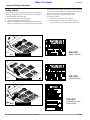
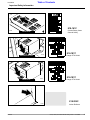
Safety Labels
Your implement comes equipped with all safety labels in place.
They were designed to help you safely operate your implement.
1. Read and follow label directions.
2. Keep all safety labels clean and legible.
3. Replace all damaged or missing labels.
4. Some new equipment installed during repair require safety
labels to be affixed to the replaced component as specified
14217
14493
Model RC15 & RC25
by the manufacturer. When ordering new components make
sure the correct safety labels are included in the request. To
order new labels go to your Land Pride dealer.
5. Refer to this section for proper label placement.
To install new labels:
a. Clean the area the label is to be placed.
b. Peel backing from label. Press firmly on surface
being careful not to cause air bubbles under label.
818-130C
Caution 540 RPM
818-130C
Model RC35
Caution 540 RPM
818-161C
14217
2
Model RC15 & RC25
RC15, RC25, and RC35 Series Rotary Cutter 312-298M
Caution Rotary Cutter
General Safety
9/25/08
Table of Contents
Land Pride
Important Safety Information
818-161C
14493
Caution Rotary Cutter
General Safety
Model RC35
Model RC25 & RC35
14242
14218
Model RC15
818-187C
Danger PTO Shield
818-187C
Danger PTO Shield
818-229C
14239
9/25/08
Amber Reflector
RC15, RC25, and RC35 Series Rotary Cutter 312-298M
3
Table of Contents
Land Pride
Important Safety Information
818-540C
Danger Guard Missing
13042
ROTATING DRIVELINE
KEEP AWAY!
818-552C
13042
Danger PTO Driveline
ROTATING DRIVELINE
KEEP AWAY!
818-552C
14242
4
RC15, RC25, and RC35 Series Rotary Cutter 312-298M
Danger PTO Driveline
9/25/08
Table of Contents
Land Pride
Important Safety Information
818-554C
Model RC15 & RC25
14217
Warning General
Cutter Safety
818-554C
14493
Model RC15 & RC25
9/25/08
Warning General
Cutter Safety
Model RC35
818-555C
14217
Danger Rotating Blade
RC15, RC25, and RC35 Series Rotary Cutter 312-298M
5
Table of Contents
Land Pride
Important Safety Information
14493
818-555C
Model RC35
Model RC15 & RC25
14493
6
Danger Rotating Blade
818-556C
14217
Thrown Object Hazard
818-556C
Model RC35
RC15, RC25, and RC35 Series Rotary Cutter 312-298M
Thrown Object Hazard
9/25/08
Table of Contents
Land Pride
Important Safety Information
818-564C
Model RC15 & RC25
14493
14217
818-564C
Model RC35
Danger Chain Guard
14493
Model RC15 & RC25
14493
9/25/08
Danger Chain Guard
818-557C
Peligro
818-557C
Model RC35
Peligro
RC15, RC25, and RC35 Series Rotary Cutter 312-298M
7
Table of Contents
Land Pride
Introduction
Introduction
Land Pride welcomes you to the growing family of new
product owners. This implement has been designed with
care and built by skilled workers using quality materials.
Proper assembly, maintenance, and safe operating practices will help you get years of satisfactory use from the
machine.
Using This Manual
This Operator’s Section is designed to help familiarize you
with safety, assembly, operation, adjustments, troubleshooting, and maintenance. Read this manual and follow
the recommendations to help ensure safe and efficient operation.
The warranty sheet should be filled out by the owner and
dealer at the time of purchase. After completion give the
dealer the white copy and send the pink copy to Great
Plains. Keep your copy in the manual for use when corresponding with the dealer.
15025
Model RC15 & RC25
To order a new Operator or Parts Manual contact your authorized dealer or write to the address listed below in the
Owner Assistance paragraph. Include the model and serial numbers of your unit.
The information contained within this manual was current
at the time of printing. Some parts may change slightly to
assure you of the best performance.
14495
Terminology:
"Right " or "Left" as used in this manual is determined by
facing the direction the machine will travel while in use unless otherwise stated.
Model RC35
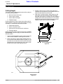
Serial Number Plate Location
Figure 1
Definitions:
NOTE: A special point of information related to it’s
preceding topic. The author’s intention is that you
read and note this information before continuing.
IMPORTANT: Information, related to it’s proceeding topic,
that the author feels would be of use.
Owner Assistance
If customer service or repair parts are required contact
your local Land Pride dealer. He has trained personnel, repair parts, and the equipment needed to service your implement.
These parts have been specially designed and should
only be replaced with genuine Land Pride parts.
Serial Number Plate
Refer to the Figure 1 for the location of your serial number
plate.
8
RC15, RC25, and RC35 Series Rotary Cutter 312-298M
For prompt service always use the serial number and
model number when ordering parts from your Land Pride
dealer. Be sure to include your serial and model numbers
in correspondence also.
Your dealer wants you to be satisfied with your new machine. If for any reason you do not understand any part of
this manual or are not satisfied with the service received,
the following actions are suggested:
1. Discuss the matter with your dealership Service Manager make sure he is aware of any problems you may
have and that he has had the opportunity to assist
you.
2. If you are still not satisfied, seek out the Owner or
General Manager of the dealership, explain the problem and request assistance.
3. For further assistance write to:
Product Support
Land Pride, Service Department
1525 East North Street
P.O. Box 5060
Salina, Ks. 67402-5060
9/25/08
Table of Contents
Land Pride
Section 1 Assembly and Setup
Section 1 Assembly and Setup
Tractor Requirements
Hitch Assembly
The RC15, RC25 and RC35 Rotary Cutters are designed
for use with tractors that are equipped with a Type 1 (540
RPM; 1 3/8" - 6 spline) rear power take-off (PTO) per
ASAE (American Society of Agricultural Engineers)
S203.12 APR93.
Refer to Figure 1-1:
NOTE: There are two mounting holes in each lower
hitch angle. The top hole is for standard category
hitch tractors; the lower hole is for smaller horsepower rated tractors without adequate ground clearance
when cutter is raised for transport.
The tractor must also provide for 3-point hitch attachments
that fall within the scope set forth by ASAE S217.11.
RC15: Category l with tractors' rated PTO horsepower no
less than 15 nor more than 50; RC25: Category I standard
or II with tractors' rated PTO horsepower no less than 20
nor more than 75; RC35: Category II with tractors' rated
PTO horsepower no less than 30 nor more than 120
NOTE: In order to maintain steering control, ballast
may need to be added to your tractor. To determine
whether or not to add the ballast, refer to your tractor’s
operator manual.
!
CAUTION!
Do not overspeed PTO or machine damage may result. This cutter is designed to be used with a tractor using a 540 RPM rear
PTO.
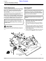
NOTE: Do not tighten hardware until assembly is
complete.
1. Assemble hitch straps (#1) to inside of lower hitch angles welded to cutter deck with hitch pin (#2), lock
washers (#3), and nuts (#4).
2. Attach hitch braces (#5) to inside of lugs welded to
deck using 3/4” bolt (#6), lock washer (#7), and nut
(#8).
3. Install pivoting upper hitch (#9) to inside of hitch straps
(#1) with hitch braces (#5) on the outside. Install 1”
bolt (#10) and nut (#11). Do not overtighten as upper
must be allowed to pivot.
4. Tighten all hardware to torque listed in the Torque Values Chart in the “Appendix” section on page 26.
Hitch Assembly Diagram
Figure 1-1
9/25/08
14244
RC15, RC25, and RC35 Series Rotary Cutter 312-298M
9
Table of Contents
Land Pride
Section 1 Assembly and Setup
RC15 Tailwheel
Driveline Installation
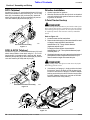
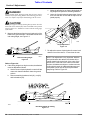
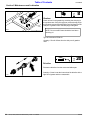
As shown in Figure 1-3, attach tailwheel boom (#1) in tailwheel risers welded to cutter deck using 1/2” x 3 1/4” long
bolts (#2), lock washers (#3), and nuts (#4). Attach tailwheel yoke spindle (#5) to boom weldment (#1) and secure with washers (#6) and cotter pin (#7).
1. Grease input shaft on gearbox.
2. Slide the driveline end with the slip clutch or shearbolt
over splined shaft of the gearbox and secure with locking device on driveline.
3-Point Tractor Hookup
!
DANGER!
Tractor hook-up can be hazardous to your health or that of your
helper. Do not allow anyone to stand between the cutter and the
tractor during hook-up operations. Do not operate the hydraulic 3-point lift controls while someone is directly behind the
tractor.
14221
RC15 Tailwheel Assembly
Figure 1-3
RC25 & RC35 Tailwheel
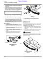
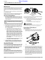
As shown in Figure 1-3, attach tailwheel boom (#1) in tailwheel risers welded to cutter deck using 3/4” -10 x 4 1//2”
long bolts (#2), lock washers (#3), and nuts (#4). Attach
tailwheel yoke spindle (#5) to boom weldment (#1) and secure with washers (#6 & #8) and roll pin (#7).
Refer to Figure 1-5:
1. Locate the cutter on a flat, level surface.
2. Determine the hitch category of the tractor that will be used:
A Category I tractor will have a lower hitch link
hole diameter of 7/8". The top link hole diameter
(implement end) will be 3/4".
A Category II tractor will have a lower hitch link
hole diameter of 1 1/8". The top link hole diameter (implement end) will be 1".
3. Slowly back the tractor up to the cutter and use the tractors 3point hydraulic control to adjust the lower link arms up or
down to match the height of the cutter hitch pins.
!
DANGER!
Engage parking brake, shut off tractor and remove key before
dismounting from the tractor.
4. If the tractor is a Category I, simply position the lower
link arms to "insert" the hitch pin into the lower hitch
link hole. If the tractor is Category II, install the adaptor
bushing on the hitch pin before insertion into the lower
link hole. (Adapter bushing not required on RC2584
and all RC35 series rotary cutters.)
RC25 & RC35 Tailwheel Assembly
Figure 1-3
14245
Tractor 3-Point Hitch
Figure 1-4
10
RC15, RC25, and RC35 Series Rotary Cutter 312-298M
14249
9/25/08
Table of Contents
Land Pride
Section 1 Assembly and Setup
5. Install a 7/16" lynch pin or other fastener (supplied by
customer) thru the hitch pin hole to lock the lower links
into position.
6. Connect the driveline to the tractor’s PTO output shaft
and secure with locking device on driveline. Connect
the safety chain to the hitch brace on the cutter to restrict outer shield of driveline from rotating.
NOTE: Chain should be attached at implement end
of driveline.
7. Connect the top link to the upper pivot hitch using the
3/4" hitch pin supplied.
8. Start the tractor and slowly engage the tractors hydraulic 3-point to lift the cutter. Check for sufficient
drawbar clearance. Move the drawbar ahead, aside,
or remove if required. Watch the telescoping movement of the driveline to ensure that it does not bottom
out while lifting the 3-point. If the driveline does bottom
out, it will require shortening:
Refer to Figure 1-5:
a. Hold the half shafts next to each other in the shortest working position and mark them.
b. Shorten the inner and outer guard tubes equally.
c. Shorten the inner and outer profiles by the same
length as the guard tubes.
d. Proper overlap is a minimum of one-half the
length of each tube, with both tubes being of equal
length.
e. Round off all sharp edges and remove burrs.
grease sliding profiles before re-assembly.
14247
Check Chain Installation
Figure 1-6
9. If check chain kit is added. install as shown in
Figure 1-6.
Safety Guards
Refer to Figure 1-7:
After Rotary Cutter assembly is complete, tighten all hardware to the torque listed on Torque Values Chart in the
“Appendix” section on page 26.
1. Install chain guard assembly (#1) to the cutter front
angle using 1/2” -13 x 1 1/2” long bolts (#2) and whiz
nuts (#3).
2. Install side chain guards (#4) to the bottom of cutter
front angle using bolts (#2) and whiz nuts (#3).
!
DANGER!
Rotary cutters have the ability to discharge objects at high
speeds; therefore, the use of front safety shields is strongly recommended when cutting along highways or in an area where
people may be present.
13588
Cutting the PTO Shafts
Figure 1-5
Safety Guard Assembly
Figure 1-7
9/25/08
RC15, RC25, and RC35 Series Rotary Cutter 312-298M
14246
11
Table of Contents
Land Pride
Section 2 Operating Instructions
Section 2 Operating Instructions
Transporting
!
!
CAUTION!
When traveling on public roads at night or during the day, use
accessory lights and devices for adequate warning to operator’s of other vehicles. Comply with all federal, state and local
laws.
NOTE: Always disengage the tractor’s PTO before
raising the cutter to transport position.
1. When raising the cutter to the transport position be
sure that driveline does not contact tractor or cutter.
2. Be sure to reduce tractor ground speed when turning;
and, leave enough clearance so the cutter does not
contact obstacles such as buildings, trees or fences.
3. Select a safe ground speed when transporting from
one area to another. When traveling on roadways,
transport in such a way that faster moving vehicles
may pass you safely.
4. When traveling over rough or hilly terrain, shift tractor
to a lower gear.
Operating Check List
In addition to design and configuration of equipment; hazard control and accident prevention are dependent upon
the awareness, concern, prudence and proper training involved in their operation, transport, maintenance and storage of equipment. Before beginning to cut the following
inspection should be performed.
Check
“Safety Rules” in this Manual.
Check oil level in gearboxes. Refer to
"Maintenance & Lubrication".
12
!
Reference
DANGER!
Rotary cutters have the ability to discharge objects at high
speeds; therefore, the use of front safety shields is strongly recommended when cutting along highways or in an area where
people may be present.
Cutting Instructions
1. Your cutter is equipped with free swinging cutting
blades to reduce shock loads to the cutter if striking
obstacles.
2. Start the machine slowly; do not use full throttle. Allow
10 seconds for cutter blades to become aligned properly before going to full power.
3. The ground speed depends on two things; the density
of the material to be cut, and the size of the tractor.
Never run fast enough to overload the tractor.
4. It is important to maintain 540 RPM PTO speed. Loss
of PTO speed will allow the blades to hinge back and
result in ragged, uneven cutting.
5. This cutter was designed to cut grass and light brush
in right-of-ways, pastures and for shredding row crop
residues.
!
Operating Checklist
CAUTION!
To prevent personal injury caused by thrown objects, the use of
front & rear safety guards is strongly recommended! To avoid
injury or death from entanglement in rotating drivelines, the
drive gearbox shields must be in place and secure when operating.
CAUTION!
Damage may occur if exceeding the cutting capacity of the cutter!
page 1
Section 5
page 22
Check that all plugs in gearbox have
been replaced properly.
Section 5
page 22
Be sure nuts and bolts are tight.
Section 1
Be certain all guards and shields are in
place.
Section 1
Lubricate the cutter as needed. Refer to
"Maintenance & Lubrication".
Section 5
page 17
RC15, RC25, and RC35 Series Rotary Cutter 312-298M
!
CAUTION!
Do not over speed PTO or machine damage may result. This
cutter is designed to be used only with a tractor having a 540
RPM rear PTO.
9/25/08
Table of Contents
Land Pride
Section 3 Adjustments
Section 3 Adjustments
Cutting Height
There are 4 primary adjustments that should be made prior to actual field operations:
a. Deck level from left to right
b. Tractor top link length
c. Tractor lower link height
d. Tailwheel height
Proper adjustment of each of these items will provide for
higher efficiency, improved cutting performance and longer blade life. The following tools will be needed:
3. Similarly, place a level on either of the main deck
channels. Use the tractors 3-point hydraulic control to
level the cutter deck from front to rear.
4. With cutter in cutting position, adjust tractor lop link
until upper hitch pin is aligned vertically with lower
hitch pins, see Figure 3-2. Position "A" is for standard
category hitch tractors and position "B" is for smaller
horsepower rated tractors without adequate ground
clearance when cutter is raised for transport.
a. Pliable tape measure
b. Spirit or carpenters level
c. Open end or hex end wrench or socket set
d. Protective gloves
Having completed 3-Point Tractor Hookup in the “Assembly and Setup” section on page 10 locate the tractor on a
flat level surface.
1. Use the tractor’s hydraulic 3-point control to lower the
cutter until the tailwheel contacts ground surface.
2. Place a spirit level or other suitable leveling device on
the front of the cutter deck as shown in Figure 3-1. Adjust either one or both of the tractors lower link height
adjustments to level the deck from left to right. Some
tractors have only a single adjusting crank.
10419
Top Link Adjustment
Figure 3-2
14240
Deck Leveling
Figure 3-1
9/25/08
RC15, RC25, and RC35 Series Rotary Cutter 312-298M
13
Table of Contents
Land Pride
Section 3 Adjustments
!
c.
DANGER!
Engage parking brake, disengage PTO, shut off tractor and remove key before proceeding. Ensure that all moving parts have
come to a complete stop before dismounting from the tractor.
!
Adjust the tailwheel up or down to the desired cutting height and replace the attaching hardware.
d. Lower the 3-point hitch and repeat steps 3 and 4
to be sure the deck is level and the top link is adjusted properly.
CAUTION!
Wear a pair of gloves when performing this operation. Go to the
back of the cutter and carefully rotate each blade to the position
shown in Figure 3-1. Avoid direct contact with the cutting edge
of the blade.
5. Measure the distance from the end (cutting tip) of the
blade to the ground surface. This distance is the nominal cutting height, see Figure 3-3.
14223
Height Adjustment
Figure 3-4
7. Re-adjust the tractors 3-point hydraulic control such
that the front of the cutter is 1" lower than the rear.
14253
Nominal Cutting Height
Figure 3-3
Refer to Figure 3-4:
6. If the cutting height is too high or too low, the tailwheel
must be adjusted as follows:
a. Use the tractors 3-point hydraulic control to lift the
cutter such that the tailwheel clears the ground
surface.
b. Remove attaching hardware; bolt (#1), nut (#2),
and lock washer (#3).
NOTE: This adjustment is very important. With the
deck positioned at this attitude, the blades will be
cutting material only at the front of the cutter. If the
deck is level, or the rear of the cutter is lower than
the front, the blades are subject to continuous material flow which results in additional blade wear and
horsepower loss as well as more frequent blade
sharpening. Refer to Figure 3-5.
14254
Best Deck Attitude for Cutting
Figure 3-5
14
RC15, RC25, and RC35 Series Rotary Cutter 312-298M
9/25/08
Land Pride
Table of Contents
Section 4 Troubleshooting
Section 4 Troubleshooting
Problem
Cause
Solution
Oil seal leaking
Gearbox overfilled
Drain to side plug hole.
Seals damaged
Replace seals
Grass or wire wrapped on
shaft in seal area
check seal areas daily
Shock load
Avoid hitting solid objects
Needs lubrication
Lubricate every 8 hours.
Scalping the ground
Raise cutting height
Cutting too fast
Reduce travel speed
PTO being engaged too
fast at high engine rpm
Slowly engage PTO at low engine rpm
Cutting over solid objects
Avoid solid objects
Contacting frame
Reduce lift height in transport position
Contacting drawbar
Reposition drawbar
Bottoming out
Shorten driveline
Driveline
telescoping tube failing
Shock load
Avoid hitting solid objects
Driveline
telescoping tube wearing
Needs lubrication
Lubricate every 50 hours
Blades wearing excessively
Cutting on
sandy ground
Raise cutting height
Contacting
ground frequently
Raise cutting height
Hitting solid objects
Avoid solid objects
Blades hitting each other
Blade carrier needs to be timed
Blades coming loose
Blades not
tightened properly
Tighten blade hardware (refer to
"Servicing Cutter Blades" on page 16.
Blade carrier becomes loose
Running loose in the past
Replace gearbox output shaft and blade carrier
Blade carrier hardware not
tight enough
Tighten to specified torque
Blade bolt holes worn
Blade hardware running loose
Replace blades and blade bolts if worn
Blade carrier bent
Hitting solid objects
Avoid hitting solid objects and replace blade carrier
Excessive side skid wear
Cutting height not level
Adjust cutter height
Soil abrasive
Adjust cutter height
Cutting too low
Adjust cutter height
Lowering too fast
Adjust rate of drop
Hitting objects when turning
Reduce speed on turns
Driveline yoke or cross failing
Driveline clutch slipping or
Shear bolt breaking
Bent Driveline (NOTE: driveline should
be repaired or replaced if bent)
Blades Breaking
Tail wheel support failing
9/25/08
RC15, RC25, and RC35 Series Rotary Cutter 312-298M
15
Table of Contents
Land Pride
Section 4 Troubleshooting
Problem
Cause
Solution
Excessive vibration
Blades locked together
Unlock blades
Driveline bent
Replace driveline
Blades loose
Tighten blade bolts
Blade carrier bent
Replace blade carrier
Blade broken
Replace blade
Blade will not swing
Remove and inspect blade
Blades have unequal weight
Replace both blades
16
RC15, RC25, and RC35 Series Rotary Cutter 312-298M
9/25/08
Land Pride
Table of Contents
Section 5 Maintenance and Lubrication
Section 5 Maintenance and Lubrication
Maintenance
Proper servicing and adjustment is the key to the long life
of any farm implement. With careful and systematic inspection, you can avoid costly maintenance, time and repair.
After using your cutter for several hours, check all bolts to
be sure they are tight.
Replace any worn, damaged or illegible safety decals by
obtaining new decals from your Land Pride Dealer.
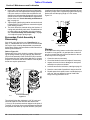
Slip Clutch Driveline
Figure 5-1
Service Cutting Blades
1. Both blades should be sharpened at the same angle
as the original cutting edge and must be replaced or
reground at the same time to maintain proper balance
in the cutting unit.
NOTE: Care should be taken in order not to remove
any more material than necessary when sharpening
blades.
2. Both blades should weigh the same after sharpening.
3. When replacing or sharpening the cutter blades, examine bolts for excessive wear and replace if necessary. To replace blades:
a. Order blade bolt Land Pride part # 802-277C.
b. Blade shim (#30), must be installed to insure a
tight and proper fit between the blade bolt and
blade. Too tight a fit may cause blade to not swing
back into proper cutting position after striking obstacles. Too loose a fit will cause play between
blade bolt and blade resulting in excessive wear
on blade carrier, blade bolts and blades. Three
sizes of shims are available: 16 ga., part no. 312075D; 18 ga., part no. 312-082D; & 20 ga., part
no. 312-089D.
c. Torque blade bolt lock nut to 450 ft. pounds. Use a
3’ long pipe to achieve proper torque.
4. If replacing dishpan, nut on gearbox output shaft
should be torqued to 450 foot/pounds and cotter pin
installed in nut with legs securely bent around nut.
14221
Prior to initial operation and after long periods of inactivity,
the Friction Clutch should be "run-in".
a. Tighten all 4 nuts uniformly until the spring load is
low enough that the clutch slips freely with the
PTO engaged.
b. Turn nuts fully back. Clutch is ready for use.
!
CAUTION!
Engage parking brake, disengage PTO, shut off tractor, and remove key before making any of the following adjustments.
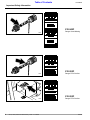
Eurocardan Clutch Run-In
Refer to Figure 5-2:
1. Using a pencil or other marker, scribe a line across the
exposed edges of the clutch plates and friction disks.
Shearbolt Driveline
Cutter drive components are protected from shock loads
by a 1/2" shear bolt. If shear bolt fails, replace with a 1/2"
x 3 1/2" long hex bolt, grade 2. Shear bolt failure can be
avoided by engaging the PTO slowly at low engine rpm.
Walterscheid Slip Clutch Run-In
Refer to Figure 5-1:
RC15 and RC25 Rotary Cutters drive components are
protected from shock loads by a two plate slip clutch and
the RC35 Rotary Cutters are protected by a four plate slip
clutch. The clutch should slip during operation to protect
the cutter from excessive loads.
9/25/08
13693
Clutch
Figure 5-2
2. Carefully loosen each of the 8 spring retainer nuts on
the clutch housing a total of EXACTLY 2 revolutions. It
will be necessary to hold the hex end of the retainer
bolt in order to count the exact number of revolutions.
3. Start the tractor and engage the PTO drive for 2-3 seconds to permit slippage of the clutch surfaces. Disengage the PTO, then re-engage a second time for 2-3
seconds. Disengage the PTO, shut off tractor and remove key. Wait for all components to stop before dismounting from tractor.
RC15, RC25, and RC35 Series Rotary Cutter 312-298M
17
Table of Contents
Land Pride
Section 5 Maintenance and Lubrication
4. Inspect the clutch and ensure that the scribed markings made on the clutch plates have changed position.
If any two marks on a friction disk and plate are still
aligned, such indicates that slippage has not occurred
and the clutch must be disassembled to separate the
friction disks, see "Clutch Assembly and Disassembly", on page 18.
5. Tighten each of the 8 spring retainer nuts on the clutch
housing EXACTLY 2 revolutions to restore the original
clutch setting pressure.
6. The clutch should be checked during the first hour of
cutting and periodically each week. An additional set
of scribe marks can be added to check for slippage.
See "Clutch Assembly and Disassembly", on page
18, to adjust for proper spring length.
Install new friction discs if needed and reassemble all components in proper order. Progressively tighten each spring
retainer bolt until the spring length is 1.010 inches,
Figure 5-4.
Eurocardan Clutch Assembly &
Disassembly
If the clutch run-in procedure, see "Clutch Run-In" on
page 17, indicated that one or more of the friction disks did
not slip, the clutch must be disassembled to separate the
friction discs. Refer to the Parts Section of this manual for a
detailed parts breakdown.
Refer to Figure 5-3:
Disassembly of the clutch is simply a matter of first removing the spring retainer nuts (#1), springs (#2) and bolts
(#3) from the assembly. Each friction disc (#4) must then
be separated from the metal surface adjacent to it. Inspect
all parts for excessive wear and condition. Clean all parts
that do not require replacement.
14714
13741
Clutch Adjustment
Figure 5-4
Storage
At the end of the working season or when the cutter will not
be used for a long period, it is good practice to clean off
any dirt or grease that may have accumulated on the cutter and any of the moving parts.
1. Clean the cutter as necessary.
2. Check the blades for wear and replace if necessary.
3. Inspect the cutter for loose, damaged or worn parts
and adjust or replace as needed.
4. Lubricate as noted in Lubrication, starting on page 21.
5. Store the cutter inside if possible for longer cutter life.
6. Repaint parts where paint is worn or scratched to prevent rust. Ask your dealer for Aerosol Land Pride
Beige touch-up paint #821-011C.
Clutch Disassembly
Figure 5-3
The original friction disc thickness is 1/8" (3.2mm) and
should be replaced if the thickness falls below 3/64"
(1.1mm). If the clutches have been slipped to the point of
"smoking", the friction discs may be damaged and should
be replaced. Heat build-up may also affect the yoke joints.
18
RC15, RC25, and RC35 Series Rotary Cutter 312-298M
9/25/08
Table of Contents
Land Pride
Section 5 Maintenance and Lubrication
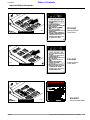
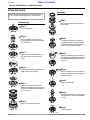
4-Plate Slip Clutch
Assembly
NOTE: Before proceeding, secure the clutch firmly in
a vise or other clamping device to prevent injury.
Step 1
Disassembly
Place the hub and friction disks into
the housing.
Step 1
Remove snap ring.
Step 2
Step 2
Remove backup ring, lock collar,
compression spring, bottom backup
ring, and balls.
Compress the Belleville Springs to
the pressure plate by tightening the
four hex nuts and then placing the assembly into the clutch housing.
Step 3
Step 3
Tighten the four hex nuts uniformly
until the clutch pack and hub are
loose.
Bend the retaining lugs inward over
the Belleville Spring edges to secure
the spring before backing the four hex
nuts off.
Step 4
Step 4
Bend all four retaining lugs out on the
edge of the clutch housing.
With the lugs bent in, loosen the four
hex nuts completely to the end of the
threaded studs.
Step 5
Insert greased balls.
Step 5
Remove the thrust plate with the
Belleville Springs and lug rings to access friction disks and hub for inspection or service.
Step 6
Install bottom backup ring, compression spring, lock collar, and top backup ring.
Step 6
Inspect friction disks and hub.
Step 7
Install snap ring.
14232
15353
9/25/08
RC15, RC25, and RC35 Series Rotary Cutter 312-298M
19
Table of Contents
Land Pride
Section 5 Maintenance and Lubrication
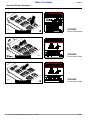
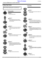
2-Plate Slip Clutch
Assembly
NOTE: Before proceeding, secure the clutch firmly in
a vise or other clamping device to prevent injury.
Step 1
Disassembly
Place the hub and friction disks into
the housing.
Step 1
Remove snap ring.
Step 2
Step 2
Remove backup ring, lock collar,
compression spring, bottom backup
ring, and balls.
Compress the Belleville Springs to
the pressure plate by tightening the
four hex nuts and then placing the assembly into the clutch housing.
Step 3
Step 3
Tighten the four hex nuts uniformly
until the clutch pack and hub are
loose.
Bend the retaining lugs inward over
the Belleville Spring edges to secure
the spring before backing the four hex
nuts off.
Step 4
Step 4
Bend all four retaining lugs out on the
edge of the clutch housing.
With the lugs bent in, loosen the four
hex nuts completely to the end of the
threaded studs.
Step 5
Insert greased balls.
Step 5
Remove the thrust plate with the
Belleville Springs and lug rings to access friction disks and hub for inspection or service.
Step 6
Install bottom backup ring, compression spring, lock collar, and top backup ring.
Step 6
Inspect friction disks and hub.
Step 7
10435
10449
20
RC15, RC25, and RC35 Series Rotary Cutter 312-298M
Install snap ring.
9/25/08
Table of Contents
Land Pride
Section 5 Maintenance and Lubrication
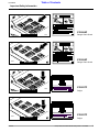
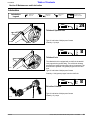
Lubrication
Lubrication
Legend
Multipurpose
spray lube
Multipurpose
grease lube
Multipurpose
oil lube
50
Intervals at which
lubrication is required
24
Tailwheel Spindle Hub
Type of Lubrication: Multipurpose Grease
14250
Quantity = 6 pumps
8
Tailwheel hub
14251
The tailwheel hub is equipped with a relief hole located directly opposite the grease fitting. The relief hole releases
pressure from inside the hub casting when it is greased. The
hub should be greased until grease purges from the relief
hole.
Type of Lubrication: Multipurpose Grease
Quantity = Until grease purges from the relief hole
8
Driveline U-Joints
Type of Lubrication: Multipurpose Grease
14190
9/25/08
Quantity = 6 pumps
RC15, RC25, and RC35 Series Rotary Cutter 312-298M
21
Table of Contents
Land Pride
Section 5 Maintenance and Lubrication
8
Gearbox
Check oil level in the gearbox by removing the side plug in
the gearbox case. If the oil level is low, remove the top plug in
the gearbox case and fill with EP90 oil until oil flows from the
side port of gearbox case. Reinstall plugs and tighten.
14252
NOTE: Do not overfill! Cutter should be level when
checking oil.
Type of Lubrication: EP90 Oil
Quantity = fill until oil flows from the side port of gearbox
case.
20
Driveline
Disconnect driveline from the tractor and slide apart
Quantity = Clean & coat the inner tube of the driveline with a
light film of grease and then reassemble
14191
22
RC15, RC25, and RC35 Series Rotary Cutter 312-298M
9/25/08
Table of Contents
Land Pride
Section 6 Specifications and Capacities
Section 6 Specifications and Capacities
RC15 Series Rotary Cutter
RC1548
RC1560
RC1572
Cutting Width
45 1/2"
57"
69"
Overall Width
50"
62"
74"
Overall Length (Including Tailwheel)
84"
96"
108"
13,096 fpm /
1,042 rpm
12,469 fpm /
794 fpm
14,955 fpm /
794 rpm
540 RPM PTO Driven Gearbox 1.93:1 Speed-Up Beveled Gears Cast Iron
Housing
540 RPM PTO Driven Gearbox 1.47:1 Speed-Up Beveled Gears Cast Iron
Housing
540 RPM PTO Driven Gearbox 1.47:1 Speed-Up Beveled Gears Cast Iron
Housing
420#
489#
641#
Recommended Tractor PTO HP
15-50
20-50
25-50
Cutting Height
1" - 9"
1" - 9"
1" - 9"
Hitch
Category I
Category I
Category I
Deck Material Thickness
12 Gauge
12 Gauge
10 Gauge
7 1/2"
7 1/2"
7 1/2"
1/2" x 3" Heat Treated Alloy
Steel Free-Swinging Suction
Blades
1/2" x 3" Heat Treated Alloy
Steel Free-Swinging Suction
Blades
1/2" x 3" Heat Treated Alloy
Steel Free-Swinging Suction
Blades
Round Pan 3/16" x 21 1/2"
Round Pan 3/16" x 21 1/2"
Round Pan 3/16" x 21 1/2"
ASAE Category 3
ASAE Category 3
ASAE Category 3
Slip Protection
Standard - 1/2" Center Shear
Bolt Protection Optional Center Bolt 2 Plate Slip
Clutch
Standard - 1/2" Center Shear
Bolt Protection Optional Center Bolt 2 Plate Slip
Clutch
Standard - 1/2" Center Shear
Bolt Protection Optional Center Bolt 2 Plate Slip
Clutch
Tailwheel
4.00 x 8 x 15 Laminated Tire
or 16" Solid Rubber Tire
4.00 x 8 x 15 Laminated Tire
or 16" Solid Rubber Tire
4.00 x 8 x 15 Laminated Tire
or 16" Solid Rubber Tire
Blade Tip Speed
Gearbox
Machine Weight (with Chain Guards)
Deck Height
Blades (2)
Blade Holders
Drive Shaft
9/25/08
RC15, RC25, and RC35 Series Rotary Cutter 312-298M
23
Table of Contents
Land Pride
Section 6 Specifications and Capacities
RC25 Series Rotary Cutter
Model
RC2560
RC2572/RCO2572
RC2584/RCO2584
Cutting Width
60”
72”
84”
Overall Width
63”
75”
87”
107”
119”
131”
-
18” {RCO2572 Only}
18” {RCO2584 Only}
Blade Tip Speed
12,384 fpm / 788 rpm
14,861 fpm / 788 rpm
14,369 fpm / 653 rpm
Gearbox
540 RPM PTO Driven
Gearbox
1.46:1 Speed-Up
Beveled Gears
Cast Iron Housing
540 RPM PTO Driven
Gearbox
1.46:1 Speed-Up
Beveled Gears
Cast Iron Housing
540 RPM PTO Driven
Gearbox
1.21:1 Speed-Up
Beveled Gears
Cast Iron Housing
725#
905#
1165#
20-75
25-75
30-75
2” - 11”
2” - 11”
2” - 11”
Category II
Category II
Category II
Category I (With Bushing to
Category II)
Category I (With Bushing to
Category II)
Category II
10 Gauge
10 Gauge
10 Gauge
8 1/2”
8 1/2”
8 1/2”
1/2” x 3” Heat Treated
Alloy Steal
Free-Swinging
Suction Blades
1/2” x 3” Heat Treated
Alloy Steal
Free-Swinging
Suction Blades
1/2” x 3” Heat Treated
Alloy Steal
Free-Swinging
Suction Blades
Round Pan 3/16” x 21 1/2”
Round Pan 3/16” x 21 1/2”
Round Pan 3/16” x 39”
ASAE Category 4
ASAE Category 4
ASAE Category 4
4 Plate Slip Clutch
4 Plate Slip Clutch
4 Plate Slip Clutch
4.00 x 8 x 15 Laminated Tire
4.00 x 8 x 15 Laminated Tire
4.00 x 8 x 15 Laminated Tire
Overall Length (Including Tailwheel)
Offset Distance
Machine Weight (with Chain Guards)
Recommended Tractor PTO HP
Cutting Height
Hitch
Hitch Pins
Deck Material Thickness
Deck Height
(Bottom of Deck to Bottom of Skid Shoe)
Blades (2)
Blade Holders
Drive Shaft
Slip Protection
Tailwheel
24
RC15, RC25, and RC35 Series Rotary Cutter 312-298M
9/25/08
Table of Contents
Land Pride
Section 6 Specifications and Capacities
RC35 Series Rotary Cutter
Model
RC3560
RC3572
RC3584
Cutting Width
57 1/2”
69”
81”
Overall Width
63”
75”
87”
110”
118”
130”
Blade Tip Speed
12,384 fpm / 788 rpm
14,861 fpm / 788 rpm
14,369 fpm / 653 rpm
Gearbox
540 RPM PTO Driven
Gearbox
1.46:1 Speed-Up
Beveled Gears
Cast Iron Housing
540 RPM PTO Driven
Gearbox
1.46:1 Speed-Up
Beveled Gears
Cast Iron Housing
540 RPM PTO Driven
Gearbox
1.21:1 Speed-Up
Beveled Gears
Cast Iron Housing
1168#
1341#
1514#
Recommended Tractor PTO HP
30-120
30-120
35-120
Cutting Height
2” - 14”
2” - 14”
2” - 14”n
Overall Length (Including Tailwheel)
Machine Weight (with Chain Guards)
Hitch
Category II
Category II
Category II
Deck Material Thickness
3/16”
3/16”
3/16”
Deck Height
(Bottom of Deck to Bottom of Skid Shoe)
9 1/2”
9 1/2”
9 1/2”
1/2” x 3” Heat Treated
Alloy Steal
Free-Swinging
Suction Blades
1/2” x 3” Heat Treated
Alloy Steal
Free-Swinging
Suction Blades
1/2” x 3” Heat Treated
Alloy Steal
Free-Swinging
Suction Blades
Round Pan 3/16” x 39”
Round Pan 3/16” x 39”
Round Pan 3/16” x 39”
ASAE Category 4
ASAE Category 4
ASAE Category 4
4 Plate Slip Clutch
4 Plate Slip Clutch
4 Plate Slip Clutch
6.00 x 9 x 21 Laminated Tire
6.00 x 9 x 21 Laminated Tire
6.00 x 9 x 21 Laminated Tire
Blades (2)
Blade Holders
Drive Shaft
Slip Protection
Tailwheel
9/25/08
RC15, RC25, and RC35 Series Rotary Cutter 312-298M
25
Table of Contents
Land Pride
Section 7 Appendix
Section 7 Appendix
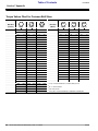
Torque Values Chart for Common Bolt Sizes
Bolt Head Identification
Bolt Size
(Inches)
in-tpi1
Grade 2
Grade 5
Bolt Head Identification
Bolt Size
(Metric)
Grade 8
N · m2
ft-lb3
N·m
ft-lb
N·m
ft-lb
mm x pitch4
1/4" - 20
7.4
5.6
11
8
16
12
M 5 X 0.8
5.8
8.8
Class 5.8
10.9
Class 8.8
Class 10.9
N·m
ft-lb
N·m
ft-lb
N·m
ft-lb
4
3
6
5
9
7
1/4" - 28
8.5
6
13
10
18
14
M6X1
7
5
11
8
15
11
5/16 - 18
15
11
24
17
33
25
M 8 X 1.25
17
12
26
19
36
27
5/16" - 24
17
13
26
19
37
27
M8X1
18
13
28
21
39
29
3/8" - 16
27
20
42
31
59
44
M10 X 1.5
33
24
52
39
72
53
3/8" - 24
31
22
47
35
67
49
M10 X 0.75
39
29
61
45
85
62
7/16" - 14
43
32
67
49
95
70
M12 X 1.75
58
42
91
67
125
93
7/16" - 20
49
36
75
55
105
78
M12 X 1.5
60
44
95
70
130
97
1/2" - 13
66
49
105
76
145
105
M12 X 1
90
66
105
77
145
105
1/2" - 20
75
55
115
85
165
120
M14 X 2
92
68
145
105
200
150
9/16" - 12
95
70
150
110
210
155
M14 X 1.5
99
73
155
115
215
160
9/16" - 18
105
79
165
120
235
170
M16 X 2
145
105
225
165
315
230
5/8" - 11
130
97
205
150
285
210
M16 X 1.5
155
115
240
180
335
245
5/8" - 18
150
110
230
170
325
240
M18 X 2.5
195
145
310
230
405
300
3/4" - 10
235
170
360
265
510
375
M18 X 1.5
220
165
350
260
485
355
3/4" - 16
260
190
405
295
570
420
M20 X 2.5
280
205
440
325
610
450
7/8" - 9
225
165
585
430
820
605
M20 X 1.5
310
230
650
480
900
665
7/8" - 14
250
185
640
475
905
670
M24 X 3
480
355
760
560
1050
780
1" - 8
340
250
875
645
1230
910
M24 X 2
525
390
830
610
1150
845
1" - 12
370
275
955
705
1350
995
M30 X 3.5
960
705
1510
1120
2100
1550
1-1/8" - 7
480
355
1080
795
1750
1290
M30 X 2
1060
785
1680
1240
2320
1710
1 1/8" - 12
540
395
1210
890
1960
1440
M36 X 3.5
1730
1270
2650
1950
3660
2700
1 1/4" - 7
680
500
1520
1120
2460
1820
M36 X 2
1880
1380
2960
2190
4100
3220
1 1/4" - 12
750
555
1680
1240
2730
2010
1 3/8" - 6
890
655
1990
1470
3230
2380
1
N· m = newton-meters
ft-lb= foot pounds
in-tpi = nominal thread dia .in inches-threads per inch
1 3/8" - 12
1010
745
2270
1670
3680
2710
2
1 1/2" - 6
1180
870
2640
1950
4290
3160
3
1 1/2" - 12
1330
980
2970
2190
4820
3560
4 mm
x pitch = nominal thread dia. in millimeters x thread pitch
Torque tolerance + 0%, -15% of torquing values. Unless otherwise specified use torque values listed above.
26
RC15, RC25, and RC35 Series Rotary Cutter 312-298M
9/25/08
Warranty
Land Pride warrants to the original purchaser that this Land Pride product will
be free from defects in material and workmanship for a period of one year, from
the date of delivery to the end user, when used as intended and under normal service and conditions for personal use; and 6 months for municipalities, golf courses, sod farms and rental purposes. This Warranty is limited to the replacement of
any defective part by Land Pride and the installation by the dealer of any such replacement part, and does not cover common wear items such as blades, belts,
tines, etc. Land Pride reserves the right to inspect any equipment or parts which
are claimed to have been defective in material or workmanship.
This Warranty does not apply to any part or product which in Land Pride’s judgment shall have been misused or damaged by accident or lack of normal maintenance or care, or which has been repaired or altered in a way which adversely
affects its performance or reliability, or which has been used for a purpose for
which the product is not designed. Misuse also specifically includes failure to
properly maintain oil levels, grease points, and driveline shafts.
Claims under this Warranty must be made to the dealer which originally sold
the product and all warranty adjustments must be made through such dealer.
Land Pride reserves the right to make changes in materials or design of the product at any time without notice.
This Warranty shall not be interpreted to render Land Pride liable for damages
of any kind, direct, consequential, or contingent to property. Furthermore, Land
Pride shall not be liable for damages resulting from any cause beyond its reasonable control. This Warranty does not extend to loss of crops, any expense or loss
for labor, supplies, rental machinery or for any other reason.
No other warranty of any kind whatsoever, express or implied, is made
with respect to this sale; and all implied warranties of merchantability and
fitness for a particular purpose which exceed the obligations set forth in this
written warranty are hereby disclaimed and excluded from this sale.
This Warranty is not valid unless registered with Land Pride within 30 days from
the date of delivery to the end user.
Land Pride Division
Great Plains Manufacturing, Inc.
Corporate Office: PO. Box 5060
Salina, Kansas 67402-5060 USA