1
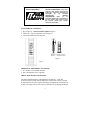
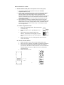
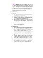
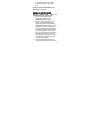
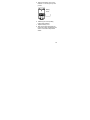
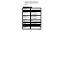
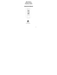
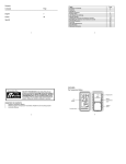
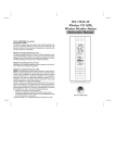
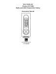
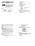
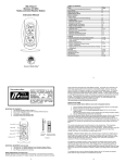
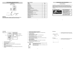
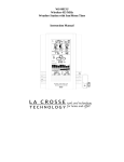
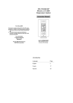
WS-7394U-IT
Wireless 915 MHz
Wireless Weather Station
Instruction Manual
TABLE OF CONTENTS
Topic
Inventory of Contents/ Additional Equipment
About WWVB
Quick Set Up Guide
Detailed Set Up Guide
Battery Installation
Start Up Sequence
Explanation of LCD Information
Function Key Layout
Program Mode
Overview of Programming Sequence
LCD Contrast Setting
Time Zone Setting
DST ON/OFF Setting
Radio-controlled Time ON/OFF Setting
12/24-hour Time Mode Setting
Setting the Time/Date Manually
Temperature Measuring Units (ºF/ºC)
Air Pressure Measuring Units (inHg/hPa)
Relative Pressure Setting
Forecast Sensitivity Setting
Features and Operation
Minimum/Maximum Temperature/Humidity
Multiple Remote Temperature/Humidity Sensors
Comfort Icon
Weather Forecast and Pressure Trend Indicators
Weather Icons
Weather Tendency Arrows
Barometric Air Pressure Reading
Air Pressure History Bar Chart
Mounting
Maintenance and Care
Troubleshooting Guide
Specifications
Warranty Information
2
Page
3
3
4
5
6
7
8
8
8
9
9
9-10
10
10-11
12
12
12
13
14
15-16
16
16
16-17
17
17
17-18
19-20
20
21
22
23-24
This product offers:
INSTANT TRANSMISSION is the stateof-the-art new wireless transmission
technology, exclusively designed and
developed
by
LA
CROSSE
TECHNOLOGY.
INSTANT
TRANSMISSION
offers
you
an
immediate update (every 4 seconds!) of
all your outdoor data measured from
the sensors: follow your climatic
variations in real-time!
INVENTORY OF CONTENTS
1. WS-7394U-IT— Wireless Weather Station (Figure 1)
2. TX29U-IT—remote temperature sensor (figure 2)
3. Instruction manual and warranty card
Mounting TX29U-IT remote
Bracket
temperature sensor
Figure 2
Figure 1
ADDITIONAL EQUIPMENT (not included)
1. Five fresh AA 1.5V alkaline batteries.
2. One wall-mounting screw (optional)
ABOUT WWVB (radio-controlled time)
The NIST (National Institute of Standards and Technology—Time and
Frequency Division) radio station, WWVB, is located in Ft. Collins, Colorado
and transmits the exact time signal continuously throughout the United States at
60 kHz. The signal can be received up to 2,000 miles away through the internal
3
antenna in the Wireless Weather Station. However, due to the nature of the
Earth’s Ionosphere, reception is very limited during daylight hours. The
Wireless Weather Station will search for a signal every night when reception is
best. The WWVB radio station derives its signal from the NIST Atomic clock
in Boulder, Colorado. A team of atomic physicists continually measure every
second of every day to an accuracy of ten billionths of a second a day. These
physicists have created an international standard, measuring a second as
9,192,631,770 vibrations of a Cesium 133 atom in a vacuum. For more
information about WWVB please see the NIST website at
http://www.boulder.nist.gov/timefreq/stations/wwvb.htm
QUICK SET-UP GUIDE
Hint: Use good quality Alkaline Batteries and avoid rechargeable batteries.
Have the Wireless Weather Station and remote temperature sensor 3 to 5
feet apart.
2. Batteries should be out of both units for 10 minutes.
3. Place the batteries into the remote temperature sensor first then Wireless
Weather Station.
(All remote temperature sensors must be started before the Wireless Weather
Station)
4. DO NOT PRESS ANY BUTTONS FOR 15 MINUTES.
In this time the Wireless Weather Station and remote temperature sensor will start to
talk to each other and the display will show both the indoor temperature and humidity, and
an outdoor temperature. If the Wireless Weather Station does not display both
temperatures after the 15 minutes please retry the set up as stated above. After both
indoor and outdoor temperatures are displayed for 15 minutes you can place your remote
temperature sensor outdoor and set your time.
1.
The remote temperature sensor should be placed in a dry, shaded area. The temperature
sensor has a range of 330 feet. Keep in mind that the 330 feet is in open air with no
obstructions and that radio waves DO NOT curve around objects. Actual transmission
range will vary depending on what is in the path of the signal. Each obstruction (roof, walls,
floors, ceilings, thick trees, etc.) will effectively cut signal range in half.
Example: A Wireless Weather Station with a 330 feet range is mounted on an interior
wall, so that the signal has to pass through one interior wall, one exterior wall, and across
the 10 feet width of the room between the 2 walls. The first wall will reduce the range to
165 feet, and the second wall will reduce the range to 87 feet. Factoring in the 10 foot
room, this leaves a maximum of 77 feet of remaining signal range.
This allowance is typically enough for a frame wall with non-metallic siding; however certain
materials can reduce range even further. Metal siding, stucco, and some types of glass
can reduce signal range by as much as ¾ or more, compared to the ½ reduction typical of
most obstructions. It is possible to receive a signal through these materials, however
maximum range will be much less due to their tendency to absorb or reflect a much larger
portion of the sensor’s signal.
4
DETAILED SET-UP GUIDE
I.
BATTERY INSTALLATION (When one temperature sensor is being used)
1.
2.
3.
First, insert the batteries to the temperature sensor (see “A. Remote
Temperature Sensor” below).
Within 2 minutes of powering up the sensor, insert the batteries to the Weather
Station (see “B. Wireless Weather Station” below). Once the batteries are in
place, all segments of the LCD will light up briefly. Following the indoor
temperature and humidity, and the time as 12:00 will be displayed. If they are not
shown in LCD after 60 seconds, remove the batteries and wait for at least 60
seconds before reinserting them. Once the indoor data is displayed user may
proceed to the next step.
After the batteries are inserted, the Weather Station will start receiving data
signal from the sensor. The outdoor temperature should then be displayed on the
Weather Station. If this does not happen after 2 minutes, the batteries will need
to be removed from both units and reset from step 1 and the signal reception
icon is no longer shown.
A. Remote Temperature Sensor
1. Remove the mounting bracket. The bracket snaps
on and off easily.
Battery
2. Remove the battery cover, by sliding the cover
Cover
down.
3. Observing the correct polarity install 2 AA
batteries. The batteries will fit tightly (to avoid
start-up problems make sure they do not spring
free).
4. Replace the battery cover by sliding upwards. Be sure battery
cover is on securely.
B. Wireless Weather Station
1. Remove the battery cover (the cover has white writing on it).
2. Observe the correct polarity, and install two Alkaline AA batteries.
3. Do not press any buttons for at least ten minutes. If a button is
pressed before the indoor weather station has received information
from the TX29U-IT sensor, no data will be received from that
sensor until reset.
4. Replace the battery cover.
5
Sensor signal
reception icon*
* When the signal is successfully received by the Weather Station, the icon will
be switched on. (If not successful, the icon will not be shown in LCD) So the user
can easily see whether the last reception was successful (icon on) or not (icon
off). On the other hand, the short blinking of the icon shows that a reception is
being done now.
•
If the signal reception is not successful on the first frequency (915MHz) for 45
seconds, the frequency is changed to 920MHz and the learning is tried another
45 seconds. If still not successful the reception is tried for 45 seconds on
910MHz. This will also be done for re-synchronization.
II. Start Up Sequence
A. Initial Start
1. Immediately after the batteries have been installed the LCD will
completely light up for a brief moment.
2. All information will then appear in normal mode, with “12:00” as
the default time and “SA.1” as the default date (2006 as the year).
3. The indoor temperature and humidity, and barometric air pressure
(as 29.92 inHg relative RH) will also be displayed.
4. There is a “satellite” icon that appears in the bottom portion of the
LCD, to the left of the outdoor temperature— this icon informs the
user that the indoor weather station is looking for signals from the
remote temperature sensor. Within five minutes the remote
temperature should be displayed—if not, remove batteries from all
units and repeat battery installation, the remote temperature sensor
first, then the indoor weather station.
B. WWVB Reception
1. Once the batteries are installed in the Wireless Weather Station it
will automatically search for the WWVB signal. If it receives a
good signal (which is unlikely during daylight hours in most
locations), the WWVB reception indicator (looks like a tower icon)
will flash. The Wireless Weather Station requires five full
minutes of good reception to successfully capture the signal and set
to the correct hour, minute, second, month, day and year. If the
signal reception is not successful within ten minutes, the signal
search will be cancelled. Next reception will take place the next
day.
2. The signal is sent from Ft. Collins, Colorado only and is similar to
an AM radio signal. Atmospheric interferences such as storms,
sunspots, and even sunlight will cause the signal to not travel as
far.
3. To maximize reception, place the Wireless Weather Station n in
a window facing Colorado, at least six feet from any electrical
source (computers, televisions, refrigerators, etc.). Do not move
the indoor weather station while it is searching for the signal.
6
4.
5.
The time and date can be manually set. Once the signal is captured,
it will override any time and date set to the time zone selected.
Once the time and date are set, the Wireless Weather Station will
conduct a search every night at midnight and correct to the
accurate time and date (Daylight Saving Time is automatic). If the
signal has been received in the past 24 hours, the reception
indicator will be displayed. After a successful reception, no more
reception attempt would be made until the following day.
III. Explanation of LCD Information
A. The below picture highlights the LCD features.
Radio-controlled time
WWVB Reception
Indicator
Date Display
Comfort Icon
Indoor Temperature
Humidity Display
Air Pressure Trend
Indicator
Forecast Icon
Barometric Air
Pressure
12-hour Air
Pressure History
Remote Sensor
Number (Up to
3 Total)
Outdoor Temperature
Display
Satellite icon (indicates
outdoor transmission)
7
B. There are many different modes the indoor weather station can be set
to. The LCD shown is the normal operating mode, and your actual data
shown will be different based on your local settings and conditions.
IV. Function Key Layout
A. The below picture shows the four function keys used in programming
and operation of your indoor weather station
V. Program Mode
The program mode is laid out in a manner that allows you to program each
function separately, or you can follow the instructions entirely to program the
Wireless Weather Station. Complete programming is usually done for the
initial set-up, and will require you to skip step 1,2 and 3 of each programming
section. The programming mode can be exited at any time by either pressing the
“CH” button, or waiting for the 15-second time-out to take effect.
A. Overview of programming mode sequence
1. LCD Contrast
4. Radio-controlled
Time ON/OFF
7. Minute
10. Date
13. Relative pressure
setting
2. Time Zone
5. 12/24-hour
time mode
8. Year
11. °F/°C
14. Forecast
sensitivity
B. LCD Contrast Setting
1. Press and hold the “SET” button for
five seconds.
2. “lcd” will appear at the top of the
display and a number will flash next
to it.
3. Press and release the “OUT/+”
button to select the desired LCD
contrast setting.
8
3. DST ON/OFF
6. Hour
9. Month
12. inHg/hPa
4.
Press and release the “SET” button to confirm the LCD contrast
setting and continue to the Time Zone setting.
C. Time Zone Setting
1. Press and hold the “SET” button for
five seconds.
2. “lcd” will appear at the top of the
display and a number will flash next to
it.
3. Press and release the “SET” button
once more to advance to the Time Zone
setting.
4. A number will flash to the left of the letter “h” at the top of the
display just below the time display.
5. Press and release the “OUT+” button to select the desired time
zone.
6. Press and release the “SET” button to confirm the Time Zone
setting and continue to the DST ON/OFF setting.
D. DST ON/OFF Setting
1. Press and hold the “SET” button for
five seconds.
2. “lcd” will appear at the top of the
display and a number will flash next to
it.
3. Press and release the “SET” button
twice more to advance to the DST
ON/OFF setting.
4. “DST” will appear above the indoor temperature/humidity display
and “ON” or “OFF” will flash above that.
5. Press and release the “OUT/+” button to select DST ON/OFF.
Note: Some locations (Arizona and parts of Indiana) do not follow Daylight
Saving Time.
6.
Press and release the “SET” button to confirm the DST ON/OFF
setting and continue to the radio-controlled Time ON/OFF setting.
E. Radio-Controlled Time ON/OFF Setting
1. Press and hold the “SET” button for
five seconds.
2. “lcd” will appear at the top of the
display and a number will flash next to
it.
3. Press and release the “SET” button
three more times to advance to the
radio-controlled time ON/OFF setting.
9
4.
5.
6.
“RCC” will appear above the indoor temperature/humidity display
and “ON” or “OFF” will flash above that.
Press and release the “OUT/+” button to select radio-controlled
time ON/OFF setting.
Press and release the “SET” button to confirm the radio-controlled
time ON/OFF setting and continue to the 12/24-hour Time Mode
setting.
F. 12/24-hour Time Mode
1. Press and hold the “SET” button for
five seconds.
2. “lcd” will appear at the top of the
display and a number will flash next to
it.
3. Press and release the “SET” button four
more times to advance to the 12/24hour time mode setting.
4. “12h” or “24h” will flash above the indoor temperature/humidity
display.
5. Press and release the “OUT/+” button to select 12 or 24-hour time
mode.
Note: In 12h mode “PM” will appear to the left of the time during PM hours.
If the time is not within the PM hours nothing will be displayed. Be sure to set
the time to the correct AM/PM time to ensure automatic reception.
6.
Press and release the “SET” button to confirm the 12/24-hour time
mode setting and continue to the Hour setting.
G. Setting The Hour Manually
The WWVB signal will override any manual set time and date information. The
time will be based on the time zone selected.
1.
2.
3.
4.
5.
6.
Press and hold the “SET” button for
five seconds.
“lcd” will appear at the top of the
display and a number will flash next to
it.
Press and release the “SET” button five
more times to advance to the Manual
Hour setting.
The hour will begin to flash at the top of the display.
Press and release the “OUT/+” button to select the desired hour.
Press and release the “SET” button to confirm the hour setting and
continue to the Minute setting.
10
H. Setting The Minutes Manually
1. Press and hold the “SET” button for five seconds.
2. “lcd” will appear at the top of the display and a number will flash
next to it.
3. Press and release the “SET” button six more times to advance to
the Manual Minutes setting.
4. The minutes will begin to flash at the top of the display.
5. Press and release the “OUT/+” button to select the desired
minutes.
6. Press and release the “SET” button to confirm the minutes and
continue to the Year setting.
I.
Setting The Year Manually
1. Press and hold the “SET” button for
five seconds.
2. “lcd” will appear at the top of the
display and a number will flash next to
it.
3. Press and release the “SET” button
seven more times to advance to the
Manual Year setting.
4. The year will begin to flash below the time display.
5. Press and release the “OUT/+” button to select the desired year.
6. Press and release the “SET” button to confirm the year and
continue to the Month setting.
J.
Setting The Month Manually
1. Press and hold the “SET” button for
five seconds.
2. “lcd” will appear at the top of the
display and a number will flash next to
it.
3. Press and release the “SET” button
eight more times to advance to the
Manual Month setting.
4. The Month will begin to flash below the time display.
5. Press and release the “OUT/+” button to select the desired month.
6. Press and release the “SET” button to confirm the month and
continue to the Date setting.
K. Setting The Date Manually
1. Press and hold the “SET” button for five seconds.
2. “lcd” will appear at the top of the display and a number will flash
next to it.
11
3.
4.
5.
6.
Press and release the “SET” button nine more times to advance to
the Manual Date setting.
The date will begin to flash below the time display.
Press and release the “OUT/+” button to select the desired date.
Press and release the “SET” button to confirm the date and
continue to the Temperature Measuring Units setting.
L. Temperature Measuring Units Selection (°F or °C)
1. Press and hold the “SET” button for
five seconds.
2. “lcd” will appear at the top of the
display and a number will flash next to
it.
3. Press and release the “SET” button ten
more times to advance to the
Temperature Measuring Units setting.
4. °F or °C will flash at the top of the display.
5. Press and release the “OUT/+” button to select the desired
temperature-measuring unit.
6. Press and release the “SET” button to confirm the temperaturemeasuring unit and continue to the Air Pressure Measuring Units
setting.
M. Air Pressure Measuring Units Selection (inHg/hPa)
1. Press and hold the “SET” button for
five seconds.
2. “lcd” will appear at the top of the
display and a number will flash next to
it.
3. Press and release the “SET” button
eleven more times to advance to the Air
Pressure Measuring Units setting.
4. inHg or hPa will flash at the top of the display.
5. Press and release the “OUT/+” button to select the desired air
pressure-measuring unit.
6. Press and release the “SET” button to confirm the air pressuremeasuring unit and continue to the Relative Pressure setting.
N. Relative Pressure Setting
1. Press and hold the “SET” button for
five seconds.
2. “lcd” will appear at the top of the
display and a number will flash next to
it.
12
3.
4.
5.
6.
Press and release the “SET” button twelve more times to advance
to the Relative Pressure setting.
The barometric air pressure will flash in the middle of the display,
just below the forecast icon
Press and release the “OUT/+” or “IN” button to select the
desired relative air pressure value.
Press and release the “SET” button to confirm the relative pressure
setting and continue to the Forecast Sensitivity setting.
O. Forecast Sensitivity Setting
1. Press and hold the “SET” button for
five seconds.
2. “lcd” will appear at the top of the
display and a number will flash next to
it.
3. Press and release the “SET” button
thirteen more times to advance to the
Forecast sensitivity setting.
4. The two air pressure tendency arrows
will begin flashing on either side of the
forecast icon and a flashing number
will appear under the forecast icon.
5. Press and release the “OUT/+” button to select the desired
forecast sensitivity setting.
Note: Barometric air pressure is usually reported as “relative air
pressure”. This reading is based on the combination of absolute air
pressure and altitude. In general, an increase in altitude will result in a
decrease in air pressure. Relative air pressure will make readings in
nearby locations relative to each other to allow for proper forecasting.
The absolute air pressure reading in the Weather Center cannot be
calibrated, only the relative air pressure.
6.
Press and release the “SET” button to confirm the forecast
sensitivity setting.
THE MANUAL SETTING IS NOW COMPLETED
13
FEATURES AND OPERATIONS
A. Minimum and Maximum Temperature and Humidity
1.
Indoor Minimum and Maximum Temperature and Humidity
The indoor weather station automatically stores the minimum and
maximum indoor temperature and humidity. The minimum and
maximum values are updated automatically when a new minimum
or maximum is recorded, or until manually reset.
a.
b.
c.
From the normal display mode, press and release the “IN” key
once to view the indoor maximum temperature and humidity
(“MAX” will be displayed above the indoor temperature and
humidity).
Press and release the “IN” key again to view the indoor
minimum temperature and humidity.
Press and release the “IN” key again to return to the normal
mode (timeout of viewing minimum/maximum values will
occur if no keys are pressed for fifteen seconds).
Note: To reset the indoor minimum and maximum temperature
and humidity, first display the values you wish to reset (minimum
or maximum). Next press and hold the “SET” key for at least
three seconds. You will see then that the values will reset to the
current temperature and humidity and corresponding time.
2.
Outdoor Minimum and Maximum Temperature
The indoor weather station automatically stores the minimum and
maximum outdoor temperature. The minimum and maximum
values are updated automatically when a new minimum or
maximum is recorded, or until manually reset.
a.
b.
c.
From the normal display mode, press and release the
“OUT/+” key once to view the outdoor maximum
temperature (“MAX” will be displayed above the outdoor
temperature).
Press and release the “OUT/+” key again to view the outdoor
minimum temperature.
Press and release the “OUT/+” key again to return to the
normal mode (timeout of viewing minimum/maximum values
will occur if no keys are pressed for fifteen seconds).
14
Note: To reset the outdoor minimum and maximum temperature,
first display the values you wish to reset (minimum or maximum).
Next press and hold the “SET” key for at least three seconds. You
will see then that the values will reset to the current temperature
and corresponding time.
B. Multiple Remote Temperature Sensors
The WS-7394U-IT is able to receive signals from 2 additional temperature
sensors. The following are instructions for the set-up of temperature sensor units
with the WS-7394U-IT. These extra sensors can be purchased through the same
dealer as this unit.
1. Remove all the batteries from the receiver and sensor(s) and wait 60
seconds. During these 60 seconds, press any button 20 times to discharge
any excess power.
2. Insert the batteries to the first temperature sensor.
3. Within 2 minutes of powering up the first sensor, insert the batteries to the
Weather Station. Once the batteries are in place, all segments of the LCD
will light up briefly. Following the indoor temperature and humidity, and the
time as 12:00 will be displayed. If they are not shown in LCD after 60
seconds, remove the batteries and wait for at least 60 seconds before
reinserting them.
4. The outdoor temperature from the first sensor (channel 1) should then be
displayed on the Weather Station. If this does not happen and the signal
reception icon is not shown, after 2 minutes, the batteries will need to be
removed from both units and reset from step 1.
5. Insert the batteries to the second sensor as soon as the outdoor
temperature readings from the first sensor are displayed on the Weather
Station.
NOTE: You must insert the batteries into the second sensor within 10
seconds of reception of the first sensor.
6. The outdoor temperature from the second sensor and the "channel 2" icon
should then be displayed on the Weather Station. If this does not happen
after 2 minute, the batteries will need to be removed from all the units and
reset from step 1.
7. Insert the batteries to the third sensor as soon as the "channel 2" icon and
outdoor data are displayed on the Weather Station. Then within 2 minutes,
the channel 3 outdoor data from the third sensor will be displayed and the
channel icon will shift back to "1" once the third sensor is successfully
received. If this is not happen, user shall restart the setting up from step 1.
NOTE: You must insert the batteries into the third sensor within 10
seconds of reception of the second sensor.
IMPORTANT: Transmission problems will arise if the setting for multiple sensors is
not followed as described above. Should transmission problems occur, it is
necessary to remove the batteries from all units and start again the set-up from
step 1.
C. Viewing and Operating with Multiple Remote Sensors
a.
To view the temperature of a different remote sensor press and
release the “CH” button. A shift from one “boxed” number to the
next should be observed in the OUTDOOR LCD.
15
b.
c.
The minimum and maximum temperature of the additional remote
sensor can be displayed by pressing the “OUT/+” button.
To reset the minimum and maximum temperature readings press
and hold the “SET” button for 3 seconds and that temperature
record for that remote sensor will be reset only.
Each remote sensor will have its own minimum and maximum values
stored.
D. Comfort Indicator for Indoor Temperature and Humidity
1.
2.
3.
The comfort level indicator appears inbetween the indoor
tempearture and humidity.
The indicator will display a “happy-face” when the temperature is
between 68°F and 79°F (20°C and 25.9°C), and the humidity is
between 45% and 65%.
A “sad-face” will be displayed when the temperature and humidity
are outside the mentioned ranges.
E. Weather Forecast Icon and Pressure Trend Indicators
The weather forecasting feature is estimated to be 75% accurate, and is
based solely upon the change of air pressure over time. The WS7394U-IT averages past air-pressure readings to provide an accurate
forecast—creating a necessity to disregard all weather forecasting for
12-24 hours after the unit has been set-up, reset, or moved from one
altitude to another (i.e. from one floor of a building to another floor).
In areas where the weather is not affected by the change of air pressure,
this feature will be less accurate.
1.
Weather Icons
There are 3 possible weather icons that will be displayed at various
times in the center of the indoor weather station.
a.
1.
Sunny—indicates that the weather is expected to improve
(not that the weather will be sunny).
b. Sun with Clouds—indicates that the weather is expected to
be fair (not that the weather will be sunny with clouds).
c.
Clouds with Rain—indicates that the weather is expected
to get worse (not that the weather will be rainy).
The weather icons change when the unit detects a change in air
pressure.
16
2.
3.
4.
5.
The icons change in order, from “sunny” to “sun with clouds” to
“clouds with rain” or the reverse.
It will not change from “sunny” directly to “clouds with rain”,
although it is possible for the change to occur quickly.
If the symbols do not change, the weather has not changed (or the
change has been slow and gradual).
The sensitivity of the change in foreacst icon is set by the user in
section F of the Detailed Set Up Guide.
F. Weather Tendency Arrows
Pressure trend
1.
2.
3.
4.
5.
arrow
Along with the forecast icon there
is a pressure tendency arrow.
There is one that points up (on the
left side of the LCD) and one that
points down (on the right side of
the LCD).
These arrows reflect current changes in the air pressure.
An arrow pointing up indicates that the air pressure is increasing
and the weather is expected to improve or remain good.
An arrow pointing down indicates that the air pressure is
decreasing and the weather is expected to become worse or remain
poor.
G. Barometric Air Pressure Reading
1.
2.
3.
The actual barometric air pressure is displayed directly under the
weather forecast icon
The relative air pressure is calibrated by the user through the
programming mode.
Please Follow the programming instructions in section F of the
Detailed Set Up Guide to set this feature.
H. Air Pressure History Bar Chart
1.
2.
3.
4.
5.
6.
The bar chart indicates the air pressure history trend over the last
12 hours in 5 steps, 0h, -3h, -6h, -9h, and -12h.
The “0h” represents the current full hour air pressure recording.
The columns represent the “hPa” (0, ±2, ±4) at specific time.
The “0” in the middle of this scale is equal to the current pressure
and each change (±2, ±4) represents how high or low in “hPa“ the
past pressure was compared to the current pressure.
If the bars are rising, the weather is getting better due to the
increase of air pressure.
If the bars go down, the air pressure has dropped and the weather is
expected to get worse from the present time “0h“.
17
Note:
For accurate barometric pressure trends, the Weather Station should operate at
the same altitude for example, it should not be moved from the ground to the
second floor of the house. Should the unit be moved to a new location, discard
readings for the next 48-60 hours.
This feature cannot be turned off.
VII. MOUNTING
Note: Before permanently mounting, ensure that the Wireless Weather Station
is able to receive signals from the sensors and WWVB signal at the desired
location. To achieve a true temperature reading, avoid mounting the remote
temperature sensor (or any sensor) where direct sunlight can reach the remote
sensor. We recommend that you mount the remote sensor on a North-facing
wall or under an eve. The sending range of the remote temperature sensor is
330-ft (100m) however obstacles such as walls, concrete, and large metal
objects can reduce the range. Place all units in their desired location, and wait
approximately 15 minutes before permanently mounting to ensure that there is
proper reception. If the Wireless Weather Station loses the signal from the
remote sensor, it will display the last temperature reading for 15 minutes. After
15 minutes of not receiving any signals, the remote temperature will display “- .-”.
A. Mounting the Remote Temperature Sensor
The remote temperature sensor can be mounted in two ways:
• with the use of screws
• using the adhesive tape
1.
MOUNTING WITH SCREWS
a.
b.
c.
d.
e.
2.
Remove the mounting bracket from the remote
temperature sensor.
Place the mounting bracket over the desired location.
Through the three screw holes of the bracket, mark
the mounting surface with a pencil.
Screw mounting bracket onto the mounting surface.
Ensure that the screws are flush with the bracket.
Insert the remote temperature sensor into the bracket.
MOUNTING WITH ADHESIVE TAPE
18
a.
b.
c.
d.
e.
With a nonabrasive solution, clean and dry the back
of the mounting bracket and the mounting surface to
ensure a secure hold. The mounting surface should
be smooth and flat.
Remove the protective strip from one side of the tape.
Adhere the tape to the designated area on the back of
the mounting bracket.
Remove the protective strip from the other side of the
tape.
Position the remote temperature sensor in the desired
location, ensuring that the Wireless Weather Station
can receive the signal.
Note: Mounting with adhesive tape is not recommended as a permanent
mounting solution. Only use the adhesive tape during set-up process.
B. Mounting the WS-7394U-IT Wireless Weather Station
The Wireless Weather Station can be mounted in two ways:
• with the table stand
• on the wall with the use of a wall hanging screw (not included)
1.
USING THE TABLE STAND
The indoor weather station comes with the table stand
already mounted. If you wish to use the table-stand all
that is required is to place the indoor weather station in an
appropriate location.
2.
WALL MOUNTING
a.
b.
c.
d.
Remove the table-stand. To do this, pull down on the
stand from the rear and rotate forward.
Fix a screw (not included) into the desired wall,
leaving approximately 3/16 of an inch (5mm)
extended from the wall.
Place the indoor weather station onto the screw using
the hanging hole on the backside.
Gently pull the indoor weather station down to lock
the screw into place.
Maintenance and Care Instructions
A. Extreme temperatures, vibration, and shock should be avoided to
prevent damage to the units.
B. Clean displays and units with a soft, damp cloth. Do not use solvents
or scouring agents; they may mark the displays and casings.
C. Do not submerge in water.
19
D. Immediately remove all low powered batteries to avoid leakage and
damage.
E. Opening the casings invalidates the warranty. Do not try to repair the
unit. Contact La Crosse Technology for repairs.
TROUBLESHOOTING
Problem: The LCD is faint.
Solution: 1) Set the LCD contrast to a higher level.
2) Replace batteries.
Problem: No outdoor temperature is displayed.
Solution: 1) Remove all batteries, reinsert into the remote temperature sensor
first, then into the indoor weather station.
2) Place remote temperature sensor closer to the indoor weather station.
3) Be sure all batteries are fresh.
4) No other interfering sources are being used (such as computer
monitors, TV sets, headphones, or speakers) in the vicinity. The
signal travels in a straight line, an electrical source near that “line”
may cause interference.
Problem: Temperature, humidity, or air pressure is incorrect.
Solution: 1) Check/Replace batteries.
2) If multiple remote sensors are in use, check location with
corresponding “boxed numbers.”
3) Move away from sources of heat/cold.
4) Adjust relative air pressure to a value from a reliable source (TV
radio, etc.).
5) The indoor weather station and remote sensors are calibrated at the
factory. If there is a consistent problem, please call La Crosse
Technology.
Problem: “- -” in humidity display.
Solution: 1) Humidity is below 1%.
Problem: WWVB time and date will not set or update
Solution: 1) Wait until overnight for signal to be received
2) Move indoor weather station away from sources of electricity
3) Place indoor weather station in window facing Colorado
4) The first reception is most difficult, as the indoor weather station
needs five continual minutes of clear signal reception. After the
initial time/date set, the indoor weather station only requires one
full minute of clear reception each night.
SPECIFICATIONS
Temperature measuring range
Indoor
14.2°F to 139.8°F with 0.2°F resolution
(-9.9°C to +59.9°C with 0.1°C resolution)
(“OFL” displayed if outside this range)
20
Outdoor
Relative humidity range
Indoor
Air pressure
Relative hPa (adjustable)
Relative inHg (adjustable)
Sensitivity setting hPa
Air pressure history
-39.8°F to 139.8°F with 0.2°F resolution
(-39.9°C to 59.9°C with 0.1°C resolution)
(“OFL” displayed if outside this range)
1% to 99% with 1% resolution
(Display “- -“ if temperature is OL.F;
display “- -“ if < 1% and “99%” if > 99%)
960 hPa to 1040 hPa
28.35 inHg to 30.72 inHg
2 hPa to 4 hPa
For the past 12 hours
(0, -3, -6, -9, and -12 hours)
Data checking intervals
Indoor temperature
Every 15 second
Indoor humidity
Every 20 seconds
Outdoor temperature
Every 4 seconds
Sensor reading update (within sensor)
Outdoor temperature
Every 4 seconds
Transmission frequency
915 MHz
Transmission range
330 feet max. (100m) in open space
Power supply
Wireless Weather Station:
2 x AA (IEC LR6) 1.5V batteries.
Remote Temperature Sensor:
2 x AA (IEC LR6) 1.5V batteries.
Dimensions (H x W x D)
Wireless Weather Station
8.75” x 4” x 1.5” (222 x 102 x 38 mm)
Remote Temperature Sensor
5.05 x 1.50 x 0.83 inches (128.3 x 38.2 x 21.2 mm)
WARRANTY INFORMATION
La Crosse Technology, Ltd provides a 1-year limited warranty on this product against manufacturing
defects in materials and workmanship.
This limited warranty begins on the original date of purchase, is valid only on products purchased
and used in North America and only to the original purchaser of this product. To receive warranty
service, the purchaser must contact La Crosse Technology, Ltd for problem determination and
service procedures. Warranty service can only be performed by a La Crosse Technology, Ltd
authorized service center. The original dated bill of sale must be presented upon request as proof of
purchase to La Crosse Technology, Ltd or La Crosse Technology, Ltd’s authorized service center.
La Crosse Technology, Ltd will repair or replace this product, at our option and at no charge as
stipulated herein, with new or reconditioned parts or products if found to be defective during the
limited warranty period specified above. All replaced parts and products become the property of La
Crosse Technology, Ltd and must be returned to La Crosse Technology, Ltd. Replacement parts and
products assume the remaining original warranty, or ninety (90) days, whichever is longer. La
Crosse Technology, Ltd will pay all expenses for labor and materials for all repairs covered by this
warranty. If necessary repairs are not covered by this warranty, or if a product is examined which is
not in need or repair, you will be charged for the repairs or examination. The owner must pay any
shipping charges incurred in getting your La Crosse Technology, Ltd product to a La Crosse
21
Technology, Ltd authorized service center. La Crosse Technology, Ltd will pay ground return
shipping charges to the owner of the product to a USA address only.
Your La Crosse Technology, Ltd warranty covers all defects in material and workmanship with the
following specified exceptions: (1) damage caused by accident, unreasonable use or neglect
(including the lack of reasonable and necessary maintenance); (2) damage occurring during shipment
(claims must be presented to the carrier); (3) damage to, or deterioration of, any accessory or
decorative surface; (4) damage resulting from failure to follow instructions contained in your
owner’s manual; (5) damage resulting from the performance of repairs or alterations by someone
other than an authorized La Crosse Technology, Ltd authorized service center; (6) units used for
other than home use (7) applications and uses that this product was not intended or (8) the products
inability to receive a signal due to any source of interference.. This warranty covers only actual
defects within the product itself, and does not cover the cost of installation or removal from a fixed
installation, normal set-up or adjustments, claims based on misrepresentation by the seller or
performance variations resulting from installation-related circumstances.
LA CROSSE TECHNOLOGY, LTD WILL NOT ASSUME LIABILITY FOR INCIDENTAL,
CONSEQUENTIAL, PUNITIVE, OR OTHER SIMILAR DAMAGES ASSOCIATED WITH THE
OPERATION OR MALFUNCTION OF THIS PRODUCT. THIS PRODUCT IS NOT TO BE
USED FOR MEDICAL PURPOSES OR FOR PUBLIC INFORMATION. THIS PRODUCT IS
NOT A TOY. KEEP OUT OF CHILDREN’S REACH.
This warranty gives you specific legal rights. You may also have other rights specific to your State.
Some States do no allow the exclusion of consequential or incidental damages therefore the above
exclusion of limitation may not apply to you.
For warranty work, technical support, or information contact:
La Crosse Technology
2809 Losey Blvd. S.
La Crosse, WI 54601
Phone: 608.782.1610
Fax: 608.796.1020
e-mail:
[email protected]
(warranty work)
[email protected]
(information on other products)
web:
www.lacrossetechnology.com
Questions? Instructions? Please visit:
www.lacrossetechnology.com/7394it
All rights reserved. This handbook must not be reproduced in any form, even in excerpts, or
duplicated or processed using electronic, mechanical or chemical procedures without written
permission of the publisher.
This handbook may contain mistakes and printing errors. The information in this handbook is
regularly checked and corrections made in the next issue. We accept no liability for technical
mistakes or printing errors, or their consequences.
All trademarks and patents are acknowledged.
22
FCC ID: OMOTX29U (sensor)
RF Exposure mobile:
The internal / external antennas used for this mobile sensor must provide a separation
distance of at least 20 cm (8 inches) from all persons and must not be co-located or
operating in conjunction with any other antenna or sensor."
Statement according to FCC part 15.19:
This device complies with Part 15 of the FCC Rules. Operation is subject to the following
two conditions: (1) this device may not cause harmful interference, and (2) this device must
accept any interference received, including interference that may cause undesired
operation.
Statement according to FCC part 15.21:
Modifications not expressly approved by this company could void the user's authority to
operate the equipment.
Statement according to FCC part 15.105:
NOTE: This equipment has been tested and found to comply with the limits for a Class B
digital device, pursuant to Part 15 of the FCC Rules. These limits are designed to provide
reasonable protection against harmful interference in a residential installation. This
equipment generates, uses and can radiate radio frequency energy and, if not installed and
used in accordance with the instructions, may cause harmful interference to radio
communications.
However, there is no guarantee that interference will not occur in a particular installation. If
this equipment does cause harmful interference to radio or television reception, which can
be determined by turning the equipment off and on, the user is encouraged to try to correct
the interference by one or more of the following measures:
•
Reorient or relocate the receiving antenna.
•
Increase the separation between the equipment and receiver.
•
Connect the equipment into an outlet on a circuit different from that to which the
receiver is connected.
Consult the dealer or an experienced radio/TV technician for help
23
WS-7013U-IT
Wireless 915 MHz
Temperature Station
Instruction Manual
1
TABLE OF CONTENTS
Topic
Inventory of Contents
Quick Setup
Detailed Setup Guide
Battery Installation
Setting the Time
Features
Minimum and
Maximum
Temperatures
Resetting Minimum
and Maximum
Temperatures
Additional remote
temperature sensors
(optional)
Mounting
Troubleshooting
Maintenance and Care
Specifications
Warranty Information
Page
2
This product offers:
INSTANT TRANSMISSION is the state-ofthe-art
new
wireless
transmission
technology, exclusively designed and
developed by LA CROSSE TECHNOLOGY.
INSTANT TRANSMISSION offers you an
immediate update (every 4 seconds!) of all
your outdoor data measured from the
sensors: follow your climatic variations in
real-time!
INVENTORY OF CONTENTS
1.
2.
3.
4.
5.
The indoor temperature station
(Figure 1)
The remote temperature sensor (TX29UIT) and mounting bracket. (Figure 2)
3 each, 1/2” Philips screws.
One strip of double sided adhesive tape.
Instruction Manual and Warranty Card.
3
Figure 1
Figure 2
ADDITIONAL EQUIPMENT
(not included)
1. 1 Philips screwdriver.
2. 2 Fresh AAA 1.5V batteries.
3. 2 Fresh AA 1.5V batteries
QUICK SETUP
Hint: Use good quality Alkaline Batteries
and avoid rechargeable batteries.
1.
2.
Have the indoor temperature station and
remote temperature sensor 3 to 5 feet
apart.
Batteries should be out of both units for
10 minutes.
4
3.
Place the batteries into the remote
temperature sensor first then into the
indoor temperature station.
(All remote temperature sensors must be
started before the indoor temperature station)
4. DO NOT PRESS ANY BUTTONS FOR
15 MINUTES.
In this time the indoor temperature station and
remote temperature sensor will start to talk to
each other and the display will show both the
indoor temperature and an outdoor
temperature. If the indoor temperature station
does not display both temperatures after the
15 minutes please retry the set up as stated
above. After both indoor and outdoor
temperatures are displayed for 15 minutes
you can place your remote temperature
sensor outdoors and set your time.
The remote temperature sensor should be
placed in a dry, shaded area. The thermohygro sensor has a range of 330 feet. Keep
in mind that the 330 feet is in open air with no
obstructions and that radio waves DO NOT
curve around objects. Actual transmission
range will vary depending on what is in the
path of the signal. Each obstruction (roof,
5
walls, floors, ceilings, thick trees, etc.) will
effectively cut signal range in half.
Example: A wireless weather station with a
330 feet range is mounted on an interior wall,
so that the signal has to pass through one
interior wall, one exterior wall, and across the
10 feet width of the room between the 2 walls.
The first wall will reduce the range to 165 feet,
and the second wall will reduce the range to
87 feet. Factoring in the 10 foot room, this
leaves a maximum of 77 feet of remaining
signal range.
This allowance is typically enough for a frame
wall with non-metallic siding; however certain
materials can reduce range even further.
Metal siding, stucco, and some types of glass
can reduce signal range by as much as ¾ or
more, compared to the ½ reduction typical of
most obstructions. It is possible to receive a
signal through these materials, however
maximum range will be much less due to their
tendency to absorb or reflect a much larger
portion of the sensor’s signal.
6
To complete the set up of your indoor
temperature station after the 15 minutes have
passed please follow the steps below.
1.
2.
3.
Press and hold the “SET/CH” button for
5 seconds.
Note: A “12h” or “24h” will appear on the
top line. (“12h” for AM/PM, “24h” for
military time)
To change between “12h” and “24h”
press and release the “MIN/MAX” button.
When you have your choice shown on
the display press and release the
“SET/CH” button once.
Note: if “12h” is selected, the temperature is
displayed in degree Fahrenheit. If “24h” is
selected, the temperature is displayed in
degree Celsius
4.
5.
An hour will now be flashing.
Press and release the “MIN/MAX” button
until the correct hour is shown.
Note: When in the 12h mode there is
“PM” displayed under the word TIME
when in the PM hours. During the AM
hours this area will be blank.
7
6. When the correct hour is shown,
press and release the “SET” button
once.
Press and release the SET button once
more and you are done.
DETAILED SETUP GUIDE
BATTERY INSTALLATION - When one
Temperature sensor is being used
1. First, insert the batteries to the
Temperature sensor (see “A.
Temperature sensor” below).
2. Within 2 minutes of powering up the
sensor, insert the batteries to the
Temperature Station (see “B. Indoor
Temperature station” below). Once the
batteries are in place, all segments of
the LCD will light up briefly. Following
the indoor temperature and the time as
12:00 will be displayed. If they are not
shown in LCD after 60 seconds, remove
the batteries and wait for at least 60
seconds before reinserting them. Once
the indoor data is displayed user may
proceed to the next step.
3. After the batteries are inserted, the
Temperature Station will start receiving
8
data signal from the sensor. The outdoor
temperature and humidity should then be
displayed on the Temperature Station. If
this does not happen after 2 minutes, the
batteries will need to be removed from
both units and reset from step 1 and the
signal reception icon is no longer shown.
A.
REMOTE TEMPERATURE SENSOR
Remove the mounting
bracket.
Battery
a. Remove battery
cover
cover
b. Observing the
correct polarity,
install 2 AA
batteries—make
sure they do not
spring free, or start-up problems
may occur. Replace cover.
B. INDOOR TEMPERATURE STATION
Note: After the batteries are installed, DO
NOT press any buttons. This may interfere
with the signals, causing temperatures to
register incorrectly.
9
a.
Remove the battery cover on the
backside. To do this, push up and
pull out.
Battery
Cover
b.
Observing the correct polarity,
install 2 AAA batteries.
c. Replace battery cover.
d. Wait 15 minutes to allow both the
indoor and outdoor temperatures are
shown on the indoor temperature
station.
10
Sensor signal
reception icon *
* When the signal is successfully received
by the Temperature Station, the icon will be
switched on. (If not successful, the icon will
not be shown in LCD) So the user can
easily see whether the last reception was
successful (icon on) or not (icon off). On
the other hand, the short blinking of the
icon shows that a reception is being done
now.
•
If the signal reception is not successful
on the first frequency (915MHz) for 45
seconds, the frequency is changed to
920MHz and the learning is tried another
45 seconds. If still not successful the
reception is tried for 45 seconds on
11
910MHz. This will also be done for resynchronization.
SETTING THE TIME
1.
Press and hold the “SET/CH” button for
5 second,
“12h” will
appear in the
TIME LCD.
2.
Press and release the “MIN/MAX”
button to select either 12h time (am/pm)
or 24h time
3.
Press and release the “SET/CH” button
2 times, the hour will flash in the upper
left corner.
4.
Press and release the “MIN/MAX”
button to set the hours
5.
Press and release the “SET/CH” button
to move to the minute setting
6.
Press and release the “MIN/MAX”
button to set the minutes.
7.
Press and release the “SET/CH” button
to activate the clock.
Note: When in 12h mode, there is only a
“PM” display, which appears under “TIME.” If
there is no display here it is AM. Make sure
you set the time accordingly.
12
Note: if “12h” is selected, the temperature is
displayed in degree Fahrenheit. If “24h” is
selected, the temperature is displayed in
degree Celsius
FEATURES
MINIMUM & MAXIMUM TEMPERATURES
1. Press and release the “MIN/MAX”
button, “MIN” appears in the
temperature LCD’s and the recorded
minimum temperatures are displayed.
2. Press and release the “MIN/MAX” button
to toggle to the maximum temperatures.
The time of occurrence of the value for
outdoor temperature will also flash.
RESETTING THE MINIMUM & MAXIMUM
TEMPERATURES
To reset both the minimum and maximum
temperatures—press and hold the
“RESET/+” button for 4 seconds.
ADDING ADDITIONAL REMOTE
SENSORS (OPTIONAL)
The WS-7013U-IT is able to receive signals
from 2 additional temperature sensors. The
following are instructions for the set-up of
13
temperature sensor units with the WS-7013UIT. These extra sensors can be purchased
through the same dealer as this unit.
1. Remove all the batteries from the
receiver and sensor(s) and wait 60
seconds. During these 60 seconds,
press any button 20 times to discharge
any excess power.
2. Insert the batteries to the first
temperature sensor.
3. Within 2 minutes of powering up the first
sensor, insert the batteries to the
Temperature Station. Once the batteries
are in place, all segments of the LCD will
light up briefly. Following the indoor
temperature and the time as 12:00 will
be displayed. If they are not shown in
LCD after 60 seconds, remove the
batteries and wait for at least 60 seconds
before reinserting them.
4. The outdoor temperature from the first
sensor (channel 1) should then be
displayed on the Temperature station. If
this does not happen and the signal
reception icon is not shown, after 2
minutes, the batteries will need to be
removed from both units and reset from
step 1.
14
5.
6.
7.
Insert the batteries to the second sensor
as soon as the outdoor temperature
readings from the first sensor are
displayed on the Temperature station.
NOTE: You must insert the batteries
into the second sensor within 45
seconds of reception of the first
sensor.
The outdoor temperature from the
second sensor and the "channel 2" icon
should then be displayed on the
Temperature station. If this does not
happen after 2 minute, the batteries will
need to be removed from all the units
and reset from step 1.
Insert the batteries to the third sensor as
soon as the "channel 2" icon and
outdoor data are displayed on the
Temperature station. Then within 2
minutes, the channel 3 outdoor data
from the third sensor will be displayed
and the channel icon will shift back to "1"
once the third sensor is successfully
received. If this is not happen, user shall
restart the setting up from step 1.
15
NOTE: You must insert the batteries into the
third sensor within 45 seconds of reception of
the second sensor.
IMPORTANT: Transmission problems will
arise if the setting for multiple sensors is not
followed as described above. Should
transmission problems occur, it is necessary
to remove the batteries from all units and start
again the set-up from
step 1.
VIEWING AND OPERATING WITH
MULTIPLE REMOTE TEMPERATURE
SENSOR UNITS
1. To view the temperature of a different
remote temperature sensor unit, press
and release the “SET/CH” button. A shift
from one “boxed” number to the next
should be observed in the OUTDOOR
LCD.
2. To view the Minimum/Maximum
temperature: first select from which
remote temperature sensor to read data
(indicated by the “boxed” number).
Pressing and releasing the “MIN/MAX”
button will toggle through the minimum
and maximum indoor temperature, and
the minimum and maximum outdoor
temperature.
16
3.
To reset the Minimum/Maximum
readings, press and hold the “MIN/MAX”
button for four seconds.
MOUNTING
Note: To achieve a true temperature reading,
avoid mounting in direct sunlight. We
recommend that you mount the remote
temperature sensor on an outside Northfacing wall. The sending range is 330ft;
obstacles such as walls, concrete, and large
metal objects will reduce the range. Place
both units in their desired location before
permanently mounting.
1. REMOTE TEMPERATURE SENSOR
Free standing:
Simply attached the stand
to the bottom of the unit
and place onto a flat
surface.
To wall mount:
a. Remove the mounting
bracket from the
temperature sensor.
17
b.
c.
Mount using either screws or adhesive
tape.
Reattach the temperature sensor to the
mounting bracket.
2. THE TEMPERATURE STATION
e. The indoor temperature station
comes with the table stand already
mounted. If you wish to use the
table-stand, all that is required is to
place the indoor temperature station
in an appropriate location.
f.
To wall mount, remove the table
stand. To do this, pull down on the
stand from the rear and rotate
forward. Fix a screw (not included)
into the desired wall, and place the
indoor temperature station onto the
screw using the hanging hole on the
backside. Gently pull the indoor
temperature station down to lock the
screw into place.
TROUBLESHOOTING
NOTE: For problems not solved, please
contact La Crosse Technology via e-mail or
phone, or visit our website,
www.lacrossetechnology.com
18
Problem: The LCD is faint
Solution: Replace batteries
Problem: No outdoor temperature I
displayed.
Solution:
1) Remove all batteries, reinsert into remote
temperature sensor first, and then into the
indoor temperature station.
2) Place remote temperature sensor closer to
the indoor temperature station.
3) Be sure all batteries are fresh.
4) Place remote temperature sensor and
indoor temperature station in position so
the straight-line signal is not passing
through more than two or three walls.
Problem: Temperatures do not match if units
are placed next to each other.
Solution: Each temperature sensor is
manufactured to be accurate to within 1
degree plus or minus and under normal
conditions; so two temperature sensors could
be as much as 2 degrees different. However,
the difference can be exaggerated further
because the temperature sensors are
designed for different working environments.
19
The indoor sensor is less responsive to
ambient air currents because of the shielding
effect of the display's case. In addition, the
case can act as a heat sink to absorb and
store heat from external sources (i.e. handling
of the case or radiant heat). In addition, the
much greater range of the outdoor
temperature sensor requires a different
calibration curve than the indoor range. Error
is usually greater at the extreme ends of a
range, making it harder to compare different
ranges with different curves. Under nonlaboratory conditions, it is difficult to
compensate for the above factors and obtain
an accurate comparison.
MAINTENANCE AND CARE
9
9
9
9
Extreme temperatures, vibration, and
shock should be avoided to prevent
damage to the units.
Clean displays and units with a soft,
damp cloth. Do not use solvents or
scouring agents; they may mark the
displays and casings.
Do not submerge in water.
Do not subject the units to unnecessary
heat or cold by placing them in the oven
or freezer.
20
9
Opening the casings invalidates the
warranty. Do not try to repair the unit.
Contact La Crosse Technology for
repairs.
SPECIFICATIONS
Transmitting
915MHz
Frequency
Measuring Temperatures
Indoor
14.1°F to 139.8.2°F with
Temperature
0.2°F resolution.
Station: Indoor
(-9.9°C to 59.8°C with
0.1°C resolution)
Indoor
-39.8 °F to 139.8°F with
Temperature
0.2°F resolution.
Station: Outdoor
(-39.8°C to 59.8°C with
0.1°C resolution)
Transmitting
Up to 330 feet open
range
space
Temperature check
Indoor
Every 15 seconds
Outdoor
Every 4 seconds
Batteries—(Alkaline recommended)
Remote
2 x AA, 1.5V
Temperature
Sensor
21
Indoor
2 x AAA, 1.5V
Temperature
Station
Dimensions: (H x W x D)
Indoor
4.3 x 2.75 x .92 in.
Temperature
(excluding table stand)
Station
(110 x 90 x 23.6 x mm)
Remote
5.05 x 1.50 x 0.83 in.
Temperature
(128.3 x 38.2 x 21.2 mm)
Sensor
Battery life
Approximately 24 months
WARRANTY INFORMATION
La Crosse Technology, Ltd provides a 1-year
limited warranty on this product against
manufacturing defects in materials and
workmanship.
This limited warranty begins on the original
date of purchase, is valid only on products
purchased and used in North America and
only to the original purchaser of this product.
To receive warranty service, the purchaser
must contact La Crosse Technology, Ltd for
problem determination and service
procedures. Warranty service can only be
performed by a La Crosse Technology, Ltd
22
authorized service center. The original dated
bill of sale must be presented upon request
as proof of purchase to La Crosse
Technology, Ltd or La Crosse Technology,
Ltd’s authorized service center.
La Crosse Technology, Ltd will repair or
replace this product, at our option and at no
charge as stipulated herein, with new or
reconditioned parts or products if found to be
defective during the limited warranty period
specified above. All replaced parts and
products become the property of La Crosse
Technology, Ltd and must be returned to La
Crosse Technology, Ltd. Replacement parts
and products assume the remaining original
warranty, or ninety (90) days, whichever is
longer. La Crosse Technology, Ltd will pay all
expenses for labor and materials for all
repairs covered by this warranty. If necessary
repairs are not covered by this warranty, or if
a product is examined which is not in need or
repair, you will be charged for the repairs or
examination. The owner must pay any
shipping charges incurred in getting your La
Crosse Technology, Ltd product to a La
Crosse Technology, Ltd authorized service
center. La Crosse Technology, Ltd will pay
23
ground return shipping charges to the owner
of the product to a USA address only.
Your La Crosse Technology, Ltd warranty
covers all defects in material and
workmanship with the following specified
exceptions: (1) damage caused by accident,
unreasonable use or neglect (including the
lack of reasonable and necessary
maintenance); (2) damage occurring during
shipment (claims must be presented to the
carrier); (3) damage to, or deterioration of,
any accessory or decorative surface; (4)
damage resulting from failure to follow
instructions contained in your owner’s
manual; (5) damage resulting from the
performance of repairs or alterations by
someone other than an authorized La Crosse
Technology, Ltd authorized service center; (6)
units used for other than home use (7)
applications and uses that this product was
not intended or (8) the products inability to
receive a signal due to any source of
interference.. This warranty covers only
actual defects within the product itself, and
does not cover the cost of installation or
removal from a fixed installation, normal setup or adjustments, claims based on
24
misrepresentation by the seller or
performance variations resulting from
installation-related circumstances.
LA CROSSE TECHNOLOGY, LTD WILL
NOT ASSUME LIABILITY FOR INCIDENTAL,
CONSEQUENTIAL, PUNITIVE, OR OTHER
SIMILAR DAMAGES ASSOCIATED WITH
THE OPERATION OR MALFUNCTION OF
THIS PRODUCT. THIS PRODUCT IS NOT
TO BE USED FOR MEDICAL PURPOSES
OR FOR PUBLIC INFORMATION. THIS
PRODUCT IS NOT A TOY. KEEP OUT OF
CHILDREN’S REACH.
This warranty gives you specific legal rights.
You may also have other rights specific to
your State. Some States do no allow the
exclusion of consequential or incidental
damages therefore the above exclusion of
limitation may not apply to you.
For warranty work, technical support, or
information contact
La Crosse Technology
2809 Losey Blvd. S.
La Crosse, WI 54601
Phone: 608.782.1610
25
Fax: 608.796.1020
e-mail:
[email protected]
(warranty work)
[email protected]
(information on other products)
web:
www.lacrossetechnology.com
Questions? Instructions? Please visit:
www.lacrossetechnology.com/7013
All rights reserved. This handbook must not
be reproduced in any form, even in excerpts,
or duplicated or processed using electronic,
mechanical or chemical procedures without
written permission of the publisher.
This handbook may contain mistakes and
printing errors. The information in this
handbook is regularly checked and
corrections made in the next issue. We
accept no liability for technical mistakes or
printing errors, or their consequences.
All trademarks and patents are
acknowledged.
26
FCC ID: OMOTX29U (sensor)
RF Exposure mobile:
The internal / external antennas used for this
mobile sensor must provide a separation
distance of at least 20 cm (8 inches) from all
persons and must not be co-located or
operating in conjunction with any other
antenna or sensor."
Statement according to FCC part 15.19:
This device complies with Part 15 of the FCC
Rules. Operation is subject to the following
two conditions: (1) this device may not cause
harmful interference, and (2) this device must
accept any interference received, including
interference that may cause undesired
operation.
Statement according to FCC part 15.21:
Modifications not expressly approved by this
company could void the user's authority to
operate the equipment.
Statement according to FCC part 15.105:
NOTE: This equipment has been tested and
found to comply with the limits for a Class B
digital device, pursuant to Part 15 of the FCC
Rules. These limits are designed to provide
reasonable protection against harmful
27
interference in a residential installation. This
equipment generates, uses and can radiate
radio frequency energy and, if not installed
and used in accordance with the instructions,
may cause harmful interference to radio
communications.
However, there is no guarantee that
interference will not occur in a particular
installation. If this equipment does cause
harmful interference to radio or television
reception, which can be determined by
turning the equipment off and on, the user is
encouraged to try to correct the interference
by one or more of the following measures:
•
Reorient or relocate the receiving
antenna.
•
Increase the separation between the
equipment and receiver.
•
Connect the equipment into an outlet on
a circuit different from that to which the
receiver is connected.
•
Consult the dealer or an experienced
radio/TV technician for help
28