1
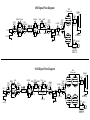
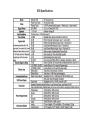
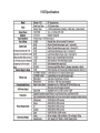
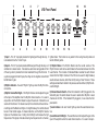
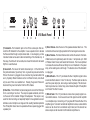
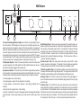
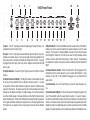
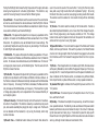
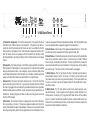
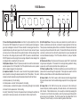
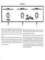
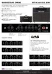
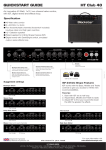
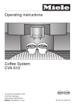
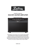
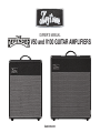
OWNER’S MANUAL
V50 and V100 GUITAR AMPLIFIERS
kustom.com
ENGLISH
FRENCH
FCC Statements
1. Caution: Changes or modifications to this unit not expressly approved by the party
responsible for compliance could void the user’s authority to operate the equipment.
2. Note: This equipment has been tested and found to comply with the limits for a Class B
digital device, pursuant to Part 15 of the FCC Rules. These limits are designed to provide
reasonable protection against harmful interference in a residential installation. This equipment
generates, uses, and can radiate radio frequency energy and, if not installed and used in
accordance with the instructions, may cause harmful interference to radio communications.
However, there is no guarantee that interference will not occur in a particular installation. If
this equipment does cause harmful interference to radio or television reception, which can be
determined by turning the equipment off and on, the user is encouraged to try to correct the
interference by one or more of the following measures:
• Reorient or relocate the receiving antenna.
• Increase the separation between the equipment and receiver.
• Connect the equipment into an outlet on a circuit different from that to which the receiver is connected.
• Consult the dealer or an experienced radio/TV technician for help.
#/50%3)'.!,&,/7$)!'2!-
V50 Signal Flow Diagram
,
EL34
0/7%2!-0
-!34%2
"2)'(4 '!).
!8
).054
2(94(-
!8
'!).34!'%3
2(94(-!34%2
"2)'(4 '!).
()
4/.%34!#+
,%!$
,%!$
,%6%,
4/.%
#(!..%, 2%6%2"
37)4#(
&//437
!8
0(!3%
6/,5-% ).6%24%2
!8
%&&%#43
%&&%#4 ,//0
37)4#(
30%!+%2
/543
)-0%$!.#%
3%,%#4/2
45"%
"//34
&//437
3%.$
,/7
&//437
%84%.3)/.
6/,5-%
2%452.
'.$,)&4
30%!+%2
%-5,!4%$
$)2%#4/54
#/50%3)'.!,&,/7$)!'2!-
V100 Signal Flow Diagram
EL34
,
0/7%2!-0
"2)'(4
!8
).054
()
2(94(-
!8
'!).34!'%3
"2)'(4 '!).
,%!$
-!34%2 42%-/,/ 2!4% 6)"2!4/ 4/.%
'!).
2(94(4/.%34!#+
-!34%2
,%!$
42%-/,/
#(!..%, 6)"2!4/
37)4#(
&//437
,%6%,
%&&%#4
37)4#( 2%6%2"
&//437)4#(
!33)'.
!8
0(!3%
6/,5-% ).6%24%2
!8
%&&%#43
%&&%#4 ,//0
37)4#(
)-0%$!.#%
3%,%#4/2
45"%
"//34
3%.$
&//437
,/7
30%!+%2
/543
2%452.
&//437
%84%.3)/.
6/,5-%
'.$,)&4
30%!+%2
%-5,!4%$
$)2%#4/54
V50 Specifications
V100 Specifications
1
2
3
4
7
6
5
8
15
V50 Front Panel
9
10
11
12
13
14
16
17
1) Input 1—This 1⁄4” input jack provides the highest gain through the amp. It tighter attack. This function is very useful for fine-tuning the amp’s tone and
feel for different guitars.
is considered to be the “normal” input.
5) Rhythm Master—The Rhythm Master sets the overall volume of the
Rhythm channel, and can be used to balance the volumes between it and the
Lead channel. The inclusion of individual Master volumes for each channel
means that the Rhythm channel of the V50 can be used for slight breakup
sounds at lower volumes, rather than strictly being a “clean” channel. These
settings are described in detail in the previous section entitled 4) Rhythm Vol3) Rhythm Indicator—the word “Rhythm” lights up when the Rhythm chanume/Pull Bright.
nel is active.
6) Channel Selector Switch—When the footswitch is NOT plugged into the
4) Rhythm Volume/Pull Bright—The Rhythm Volume control adjusts the gain
footswitch jack, this switch allows the user to select either Rhythm or Lead
at the input of the amplifier when the Rhythm channel is active. It is used in
channels on the V50. If the footswitch IS plugged in, it over-rides the front
conjunction with the Rhythm Master to adjust the amount of distortion and
panel switch.
volume for the channel. For cleaner sounds, this control should be set to lower settings and the Master set higher...for slight breakup, the controls should 7) Lead Indicator—the word “Lead” lights up when the Lead channel is acbe set in their middle ranges...for heavier distortion, set the Rhythm Volume tive.
higher and the Master lower. Pulling the Pull Bright will increase the high 8) Lead Volume/Pull Bright—The Lead Volume control adjusts the gain at the
frequencies of the signal, while also reducing low frequencies for a chunkier, input of the amplifier when the Lead channel is active. It is used in conjunc2) Input 2—This 1⁄4” input jack provides 6dB lower gain through the amp, so it
will allow for a cleaner sound. It can also be useful when using pedals in front
of the amp, since it provides them more headroom through the front end. If
a guitar is plugged into both Inputs, then they will mix together and will both
be 6dB lower in gain.
tion with the Lead Master to adjust the amount of distortion and volume for
the channel. For cleaner sounds, this control would be set to lower settings
and the Master set higher...for slight breakup, the controls would be set in
their middle ranges...for heavier distortion, set the Lead Volume higher and
the Master lower. Pulling the Pull Bright will increase the high frequencies of
the signal, while also reducing low frequencies for a chunkier, tighter attack.
This function is very useful for fine-tuning the amp’s tone and feel for different
guitars.
13) Reverb Intensity—The Reverb Intensity controls the amount of reverberation effect in the amplifier. This effect is created by an authentic spring
reverb pan, and sounds essentially like playing the amp in a large room. The
Reverb can be defeated with the footswitch, or by turning the Intensity control
fully counter-clockwise.
14) Reverb Tone—A traditional Kustom feature, the Reverb Tone allows the
user to fine-tune the sound of the reverb effect. Turning this Tone fully clockwise yields a very bright reverb effect with emphasized “spring.” By turning
9) Lead Master—The Lead Master sets the overall volume of the Lead chan- the Reverb Tone down, a warmer, less-springy sounding reverb effect results.
nel, and can be used to balance the volumes between it and the Rhythm The warmer reverb tone allows for more reverb intensity without dominating
channel. The interactions between Volume and Master are described in detail the sound.
in the previous section entitled 8) Lead Volume/Pull Bright.
15) Jeweled Pilot Light—Indicates that the amplifier’s power switch is in the
10) Bass EQ—This passive EQ adjusts the low frequency equalization of the On position.
amplifier. It interacts with the Middle and Treble as described in the 12) Treble
16) On/Off Power—Provides AC power to the amplifier when in the “On”
EQ section. For a tighter low end, use the Bass EQ set to lower settings. This
position—switched to the left.
is particularly helpful when using the amp at very loud settings. This EQ works
17) Standby—This allows the amplifier to be powered up, but with the tubes
for both Rhythm and Lead channels.
in a non-operational mode. The Standby can be used instead of the power
11) Middle EQ—This passive EQ adjusts the midrange equalization of the
switch between performance sets, since it allows the amp to “shut down”
amplifier. It interacts with the Bass and Treble EQ as described in the 12)
while keeping the tubes warm and ready to go. It’s also best to power the
Treble EQ section. For a heavier, more distorted sound, set the Middle lower.
amp up with this switch set to the right/off position until the tubes have had a
For more of a vintage-style, cleaner sound, set the Middle higher. This EQ
few minutes to warm up, although modern tubes are more tolerant of this.
works for both Rhythm and Lead channels.
12) Treble EQ—This passive EQ adjusts the high frequency equalization of
the amplifier, but also interacts with the Bass and Middle controls as follows:
As the Treble is increased, the Bass automatically decreases and the Middle
slides down in frequency. Conversely, if the Treble is decreased, the Bass
automatically increases and the Middle slides up in frequency. This interaction is typical of vintage-style passive EQ, and is responsible for the increased
effectivity of such a simple system.
1
2
3
4
V50 Back Panel
1) Footswitch—The Footswitch jack on the V50 is a stereo jack that connects the V50 footswitch to the amplifier. It uses a special circuit to decode
the three switches through a simple stereo cable. In an emergency, a mono
instrument cable can be used to allow footswitching of the channels only. In
this setup, the LEDs will not be visible, but at least the footswitch will select
Rhythm or Lead channels.
2) Ground Lift—The Ground Lift switch disconnects pin 1 of the XLR Direct
Out jack to eliminate a “ground loop” hum. A ground loop can exist when the
V50 and the mixer it is plugged into are connected to grounded outlets that
are in physically different locations and/or on different circuits, and should
only be used if there is an audible hum. Pressing the ground lift does not
disconnect the ground connection from the V50’s chassis.
3) Direct Out—The XLR Direct Out jack is designed to connect the V50 amplifier to a recording or live mixer. The output is speaker-emulated, and mimics the sound of the Celestion Vintage 30 loudspeaker. This output is very
useful for direct recording, and especially helpful for live applications since it
eliminates a live microphone on stage and the resulting feedback potential.
The V50 amplifier should never be operated without a speaker plugged into
a speaker jack.
5
6
7
4) Direct Volume—Sets the level of the speaker-emulated direct out. This
control should be set as high as possible for the best signal-to-noise ratio.
5) Boost Volume—The Boost Volume knob controls the amount of footswitchable boost, and is particularly useful for solos. It will provide up to 10dB
of “Master Volume” boost, and boosts both channels. The tone is optimized
to increase the volume without sacrificing too much headroom in the power
amp, so the resulting solo cuts through. The boost is active if the footswitch
is unplugged.
6) Effects Return—This 1⁄4” jack breaks the flow of amplifier signal to allow
an external effects device to “return” to the amp. The Return jack can also be
used for a power amp input, when using an external preamp. This all-tube effects loop is known as a “series” loop, since it breaks the path of the amplifier
and “inserts” the effect in series.
7) Effects Send—This 1⁄4” jack delivers a tube-driven preamp signal to external effects devices. It can be used to send the signal to another amplifier
to run multiple amps. Connecting a 1⁄4” plug does NOT break the flow of the
amplifier signal. To connect two Defender amplifiers in stereo, a stereo effects
device can be driven from one Defender amp’s Send, and the device’s two
stereo outputs can be returned to both Defender amps’ Returns.
*.1&%"/$&4&-&$503
"41&",&3.645#&1-6((&%*/
41&",&30651654
83.473.4
50
28
V50 Bottom
-
EL34
-
EL34
1) Power Cord Receptacle/Fuse Holder: Insert the AC cord (provided) firmly into
the AC connector. NOTE: Replace the AC power cord if protective jacket is damaged or ground pin is damaged or removed. The fuse is located in a housing just
below the receptacle. Replace only with same type and size. To remove the fuse,
remove AC power cord and pull out on the tab above the fuse symbol located on the
fuse carriage. Place the new fuse in the carriage clip and re-insert. NOTE: To prevent
an electrical hazard, DO NOT replace fuse without using the fuse carriage. Replace
the fuse carriage if lost or damaged before re-inserting the AC power cord.
2 & 3) Speaker Outputs—These 1⁄4” jacks are provided to connect the internal and/
or external speakers to the V50 amplifier. The V50 amplifier should never be operated without a speaker plugged into a speaker jack.
4) Impedance Selector—This switch is used to select the appropriate impedance,
and is important in achieving the desired results from the V50 amplifiers. The correct
impedance should be selected using the Impedance Selector Switch as follows:
a. Internal speaker only: 16 ohm setting
b. Internal speaker + external 16 ohm speaker: 8 ohm setting
c. Internal speaker + external 8 ohm speaker: 4 ohm setting, although it’s not
matched
d. External 16 ohm speaker alone: 16 ohm setting
Incorrectly “mismatching” the amp to the speaker should not damage the amplifier,
but would result in lower output powers, and could result in shorter output tube
life.
"9
"9
"9
"9
5) EL34 Output Tubes—These power tubes were selected to provide the best combination of performance and tube life, and shouldn’t require adjustment to their bias.
The amp uses a mixed-bias system which is a combination of fixed and self-bias
techniques to give the user the best of both worlds. The result is that the amp will
control its own bias to a certain point, but without the typical reduction in power
associated with normal self-biased amp designs. The V50 uses two EL34s in a
“push-pull” amplifier configuration.
6) Phase Inverter Tube—The phase inverter tube uses a single 12AX7 in what’s
called a long-tail pair configuration. This results in the most signal swing possible
for driving a power amp, and the most symmetrical drive capability, as well.
7) Effects Loop/Boost Tube—The Defender amplifiers use an all-tube effects loop
to preserve the tube sound through the signal path. This single tube is used for both
the Effects Loop Send/Return and the footswitchable Volume Boost circuit.
8) Preamp Tube 2—This 12AX7 is used on both channels, but has the biggest impact to the lead channel since it has the additional stage required for the very large
amount of gain.
9) Preamp Tube 1—This 12AX7 is the input tube, and as such, is the most likely to
cause microphonic problems, especially in the lead channel, and it is also shared
by both channels. If tube feedback occurs, it can usually be corrected by swapping
this first tube with one of the other tube locations, since they have less gain following
them and are less prone to feedback. The first tube also has the greatest affect on
the “cleaned up” tone of the amp, i.e. the tone when the guitar is turned down.
1
2
3
4
7
6
5
8
18
V100 Front Panel
9
10
11
12
1) Input 1—This 1⁄4” input jack provides the highest gain through the amp. It is
considered to be the “normal” input.
2) Input 2—This 1⁄4” input jack provides 6dB lower gain through the amp, so it
will allow for a cleaner sound. It can also be useful when using pedals in front
of the amp, since it provides more headroom through the front end. If a guitar
is plugged into both inputs, then they will mix together and will both be 6dB
lower in gain.
3) Rhythm Indicator—the word “Rhythm” lights up when the Rhythm channel
is active.
4) Rhythm Volume/Pull Bright—The Rhythm Volume control adjusts the gain
at the input of the amplifier when the Rhythm channel is active. It is used
in conjunction with the Rhythm Master to adjust the amount of distortion and
volume for the channel. For cleaner sounds, this control would be set to lower
settings and the Master set higher. For slight breakup, the controls would be
set in their middle ranges. For heavier distortion, set the Rhythm Volume higher
and the Master lower. Pulling the Pull Bright will increase the high frequencies
of the signal, while also reducing low frequencies for a chunkier, tighter attack.
This function is very useful for fine-tuning the amp’s tone and feel for different
guitars.
13
14
15
16
17
19
20
5) Rhythm Master—The Rhythm Master sets the overall volume of the Rhythm
channel, and can be used to balance the volumes between it and the Lead
channel. The inclusion of individual Master volumes for each channel means
that the Rhythm channel of the V100 can be used for slight breakup sounds
at lower volumes, rather than strictly being a “clean” channel. These settings
are described in detail in the previous section entitled 4) Rhythm Volume/Pull
Bright.
6) Channel Selector Switch—When the footswitch is NOT plugged into the
footswitch jack, this switch allows the user to select either Rhythm or Lead
channels on the V100. If the footswitch IS plugged in, it over-rides the front
panel switch.
7) Lead Indicator—the word “Lead” lights up when the Lead channel is active.
8) Lead Volume/Pull Bright—The Lead Volume control adjusts the gain at the
input of the amplifier when the Lead channel is active. It is used in conjunction with the Lead Master to adjust the amount of distortion and volume for the
channel. For cleaner sounds, this control would be set to lower settings and the
Master set higher. For slight breakup, the controls would be set in their middle
ranges. For heavier distortion, set the Lead Volume higher and the Master lower.
Pulling the Pull Bright will increase the high frequencies of the signal, while also
reducing low frequencies for a chunkier, tighter attack. This function is very
useful for fine-tuning the amp’s tone and feel for different guitars.
9) Lead Master—The Lead Master sets the overall volume of the Lead channel
and can be used to balance the volumes between it and the Rhythm channel.
The interactions between Volume and Master are described in detail in the previous section entitled 4) Lead Volume/Pull Bright.
10) Bass EQ—This passive EQ adjusts the low frequency equalization of the
amplifier. It interacts with the Middle and Treble as described in the 12) Treble
EQ section. For a tighter low end, use the Bass EQ set to lower settings. This
is particularly helpful when using the amp at very loud settings. This EQ works
for both Rhythm and Lead channels.
11) Middle EQ—This passive EQ adjusts the midrange equalization of the amplifier. It interacts with the Bass and Treble EQ as described in the 12) Treble EQ
section. For a heavier, more distorted sound, set the Middle lower. For more of
a vintage-style, cleaner sound, set the Middle higher. This EQ works for both
Rhythm and Lead channels.
12) Treble EQ—This passive EQ adjusts the high frequency equalization of the
amplifier, but also interacts with the Bass and Middle controls as follows: As
the Treble is increased, the Bass automatically decreases and the Middle slides
down in frequency. Conversely, if the Treble is decreased, the Bass automatically increases and the Middle slides up in frequency. This interaction is typical
of vintage-style passive EQ, and is responsible for the increased effectivity of
such a simple system.
13) Reverb Intensity—The Reverb Intensity controls the amount of reverberation effect in the amplifier. This effect is created by an authentic spring reverb
pan, and sounds essentially like playing the amp in a large room. The Reverb
can be defeated with the footswitch, or by turning the Intensity control fully
counter-clockwise.
14) Reverb Tone—A traditional Kustom feature, the Reverb Tone allows the
user to fine-tune the sound of the reverb effect. Turning this Tone fully clockwise yields a very bright reverb effect with emphasized “spring.” By turning
the Reverb Tone down, a warmer, less-springy sounding reverb effect results.
The warmer reverb tone allows for more reverb intensity without dominating
the sound.
15) Tremolo—This control sets the intensity of the Tremolo effect. Tremolo is
also called Amplitude Modulation, since it is an effect that changes the amplitude of the dry signal using a low frequency oscillator, or LFO. This vintage
Kustom circuit uses the Speed control to set the speed of the oscillation, and
can be set from very slow to a very high speed.
16) Speed/Pull Active—This control sets the speed of the Vibrato and Tremolo
effects, which are synchronized. If the switch is pushed in, the Vibrato/Tremolo
circuit is not in the signal path. When the footswitch is engaged, it will override
the Pull Active switch if the Footswitch Assignment Switch is in the Out position.
17) Vibrato—This vintage Kustom circuit creates a pitch shift, otherwise known
as Frequency Modulation, since it affects the apparent frequency of the dry signal using the LFO. It uses the Speed control to set the speed of oscillation, and
when combined with the Tremolo control, can simulate many different effects,
from simple Tremolo, to phase shifter sounds, to rotary speaker simulations.
18) Jeweled Pilot Light—Indicates that the amplifier’s power switch is in the
“On” position.
19) On/Off Power—Provides AC power to the amplifier when in the “On” position—switched to the left.
20) Standby—This allows the amplifier to be powered up, but with the tubes in
a non-operational mode. The Standby can be used instead of the power switch
between performance sets, since it allows the amp to “shut down” while keeping the tubes warm and ready to go. It’s also best to power the amp up with
this switch set to the right/off position until the tubes have had a few minutes to
warm up, although modern tubes are more tolerant of this.
1
2
3
4
5
V100 Back Panel
1) Footswitch Assignment—This button selects which of the amp’s effects are
controlled by the “Effects” button on the footswitch. If the switch is IN, the footswitch will control the Reverb and the Tremolo will only be controlled by the Pull
Active Switch on the Speed control. If the Footswitch Assignment button is OUT,
then the Reverb will be active always, and the footswitch will remotely control
the Tremolo/Vibrato, overriding the setting of the Pull Active Switch on the Speed
control.
2) Footswitch—The Footswitch jack on the V100 is a stereo jack that connects the
V100 footswitch to the amplifier. It uses a special circuit to decode the 3 switches
through a simple stereo cable. In an emergency, a mono instrument cable can be
used to allow footswitching of the channels only. In this setup, the LEDs will not be
visible, but at least the footswitch will select Rhythm or Lead channels.
3) Ground Lift—The Ground Lift switch disconnects pin 1 of the XLR Direct Out
jack to eliminate a “ground loop” hum. A ground loop can exist when the V100 and
the mixer it is plugged into are connected to grounded outlets that are in physically
different locations and/or on different circuits, and should only be used if there is an
audible hum. Pressing the ground lift does not disconnect the ground connection
from the V100’s chassis.
4) Direct Out—The XLR Direct Out jack is designed to connect the V100 amplifier to a recording or live mixer. The output is speaker-emulated, and mimics the
sound of the Celestion Vintage 30 loudspeaker. This output is very useful for direct
recording, and especially helpful for live applications since it eliminates a live mi-
6
7
8
crophone on stage and the resulting feedback potential. The V100 amplifier should
never be operated without a speaker plugged into a speaker jack.
5) Direct Volume—Sets the level of the speaker-emulated direct out. This control
should be set as high as possible for the best signal-to-noise ratio.
6) Boost Volume—The Boost Volume knob controls the amount of footswitchable
boost, and is particularly useful for solos. It will provide up to 10dB of “Master
Volume” boost, and boosts both channels. The tone is optimized to increase the
volume without sacrificing too much headroom in the power amp, so the resulting
solo cuts through. The boost is active if the footswitch is unplugged.
7) Effects Return—This 1⁄4” jack breaks the flow of amplifier signal to allow an
external effects device to “return” to the amp. The Return jack can also be used
for a power amp input, when using an external preamp. This all-tube effects loop
is known as a “series” loop, since it breaks the path of the amplifier and “inserts”
the effect in series.
8) Effects Send—This 1⁄4” jack delivers a tube-driven preamp signal to external effects devices. It can be used to send the signal to another amplifier to run
multiple amps. Connecting a 1⁄4” plug does NOT break the flow of the amplifier
signal. To connect two Defender amplifiers in stereo, a stereo effects device can
be driven from one Defender amp’s Send, and the device’s two stereo outputs can
be returned to both Defender amp Returns.
*.1&%"/$&4&-&$503
41&",&30651654
"41&",&3.645#&1-6((&%*/
100
83.473.4
40
V100 Bottom
-
EL34
-
EL34
-
EL34
1) Power Cord Receptacle/Fuse Holder: Insert the AC cord (provided) firmly into the
AC connector. NOTE: Replace the AC power cord if protective jacket is damaged or
ground pin is damaged or removed. The fuse is located in a housing just below the receptacle. Replace only with same type and size. To remove the fuse, remove AC power
cord and pull out on the tab above the fuse symbol located on the fuse carriage. Place
the new fuse in the carriage clip and re-insert. NOTE: To prevent an electrical hazard,
DO NOT replace fuse without using the fuse carriage. Replace the fuse carriage if lost
or damaged before re-inserting the AC power cord.
2 & 3) Speaker Outputs—These 1⁄4” jacks are provided to connect the internal and/or
external speakers to the V100 amplifier. The V100 amplifier should never be operated
without a speaker plugged into a speaker jack.
4) Impedance Selector—This switch is used to select the appropriate impedance,
and is important in achieving the desired results from the V100 amplifiers. The correct
impedance should be selected using the Impedance Selector Switch as follows:
a. Internal speaker only: 16 ohm setting
b. Internal speaker + external 16 ohm speaker: 8 ohm setting
c. Internal speaker + external 8 ohm speaker: 4 ohm setting, although it’s not matched
d. External 16 ohm speaker alone: 16 ohm setting
Incorrectly “mismatching” the amp to the speaker should not damage the amplifier, but
would result in lower output powers, and could result in shorter output tube life.
-
EL34
"9
"9
"9
"9
5) EL34 Output Tubes—These power tubes were selected to provide the best combination of performance and tube life, and shouldn’t require adjustment to their bias.
The amp uses a mixed-bias system which is a combination of fixed and self-bias techniques to give the user the best of both worlds. The result is that the amp will control its
own bias to a certain point, but without the typical reduction in power associated with
normal self-biased amp designs. The V100 uses four EL34s in a “push-pull” amplifier
configuration.
6) Phase Inverter Tube—The phase inverter tube uses a single 12AX7 in what’s called
a long-tail pair configuration. This results in the most signal swing possible for driving
a power amp, and the most symmetrical drive capability, as well.
7) Effects Loop/Boost Tube—The Defender amplifiers use an all-tube effects loop to
preserve the tube sound through the signal path. This single tube is used for both the
Effects Loop Send/Return and the footswitchable Volume Boost circuit.
8) Preamp Tube 2—This 12AX7 is used on both channels, but has the biggest impact
to the lead channel since it has the additional stage required for the very large amount
of gain.
9) Preamp Tube 1—This 12AX7 is the input tube, and as such, is the most likely to
cause microphonic problems, especially in the lead channel, and it is also shared by
both channels. If tube feedback occurs, it can usually be corrected by swapping this
1st tube with one of the other tube locations, since they have less gain following them
and are less prone to feedback. The first tube also has the greatest affect on the
“cleaned up” tone of the amp, i.e. the tone when the guitar is turned down.
Footswitch
1
1) Lead—The Lead footswitch selects between Rhythm and Lead Channels on the amplifier, regardless of the setting of the channel selector
switch on the front panel. If the LEAD word is backlit, then the Lead
channel is active. If the LEAD word is unlit, then the Rhythm channel is
active.
2) Boost—The Boost footswitch selects the adjustable volume boost as
determined on the back of the Defender amplifier. This gives up to 10dB
of “master” volume boost and the tone is optimized for solos. It affects
either channel, and when the Boost is backlit, the Volume Boost control
on the amp is functional.
24
2
3
3) Effect—The Effect footswitch activates the Reverb on the V50, and
is switch assignable for Reverb or Tremolo on the V100. When Effect is
backlit, the appropriate effect is activated.
Emergency Mono Cable Use: If the stereo cable or footswitch were damaged, a regular instrument amp cable or single button footswitch can be
used to provide limited capability. If a mono cable were used, the Channel Selection(Lead) button would select between Rhythm and Lead, but it
would not illuminate. Also, the Boost function would be disabled, and on
the V50, the Reverb would also be disabled. On the V100, either Reverb
or Tremolo could still be used since selecting the other with the footswitch
assign button would disable it.
www.kustom.com
Kustom Amplification, Inc.
3015 Kustom Drive
Hebron, Kentucky
USA 41048
888-4-KUSTOM (888-458-7866)
All specifications are subject to change without prior notice. ©2010 Kustom