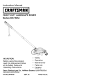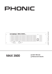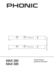
1
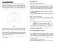
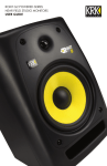
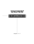
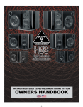
U
S
E
R
G
KRK V SERIES 2
BI-AMPLIFIED
STUDIO MONITOR
KRK SYSTEMS LLC.
HTTP://WWW.KRKSYS.COM
LITK00015
U
I
D
E
Contents
IMPORTANT SAFETY INSTRUCTIONS
CAUTION ATTENTION:
RISK OF ELECTRIC
SHOCK DO NOT OPEN
RISQUE DE CHOC ELECTRIQUE
NE PAS OUVRIR
CAUTION: TO REDUCE THE RISK OF ELECTRIC
SHOCK, DO NOT REMOVE COVER (OR BACK). NO
USER SERVICEABLE PARTS INSIDE. REFER SERVICING
TO QUALIFIED SERVICE PERSONNEL.
Warning: To reduce the risk of fire or electric shock, do not
expose this unit to rain or moisture.
The lightning flash with an arrowhead symbol within an equilateral
triangle, is intended to alert the user to the presence of uninsulated
ìdangerous voltageî within the productí s enclosure that may be of
sufficient magnitude to constitute a risk of electric shock to persons.
The exclamation point within an equilateral triangle is intended to
alert the user to the presence of important operating and
maintenance (servicing) instructions in the literature accompanying
the product.
Do not place this unit on an unstable cart, stand or tripod, bracket
or table. The unit may fall, causing serious injury to a child or adult
and serious damage to the unit. Use only with a cart, stand, tripod,
bracket or table recommended by the manufacturer or sold with
the unit. Any mounting of the device on a wall or ceiling should
follow the manufacturerís instructions and should use a mounting
accessory recommended by the manufacturer.
An appliance and cart combination should be moved with care.
Quick stops, excessive force and uneven surfaces may cause the
appliance and cart combination to overturn.
1. "An apparatus with Class I construction shall be connected to
a mains sockets outlet with protective earthing connection."
2. "Where the mains plug or an appliance coupler is used as the
disconnect device, the disconnection device shall remain readily
operable"
3. "1A fuse is used to US market, voltage will be set to 115V before
shipment: 500mA fuse is used to European market, voltage will
be set to 230V before shipment."
ATTENTION
POUR …VITER LES CHOC ELECTRIQUES, INTRODUIRE LA
LAME LA PLUS LARGE DE LA FICHE DANS LA BORNE
CORRESPONDANTE DE LA PRISE ET POUSSER JUSQUíAU
FOND.
CAUTION
TO PREVENT ELECTRIC SHOCK, MATCH WIDE BLADE OF
PLUG TO WIDE SLOT FULLY INSERT.
If an indoor antenna is used (either built into the set or installed
separately), never allow any part of the antenna to touch the metal
parts of other electrical appliances such as a lamp, TV set etc.
CAUTION
POWER LINES
OUTDOOR ANTENNA GROUNDING
If an outside antenna is connected to your tuner or tunerpreamplifier, be sure the antenna system is grounded so as to
provide some protection against voltage surges and built-up static
charges. Article 810 of the National Electrical Code, ANSI/NFPA No.
70-1984, provides information with respect to proper grounding of
the mast and supporting structure, grounding of the lead-in wire to
an antenna discharge unit, size of grounding conductors, location of
antenna discharge unit, connection to grounding electrodes and
requirements for the grounding electrode.
a. Use No. 10 AWG (5.3mm2) copper, No. 8 AWG (8.4mm2)
aluminium, No. 17 AWG (1.0mm2) copper-clad steel or bronze
wire, or larger, as a ground wire.
b. Secure antenna lead-in and ground wires to house with stand-off
insulators spaced from 4-6 feet (1.22 - 1.83 m) apart.
c. Mount antenna discharge unit as close as possible to where leadin enters house.
d. Use jumper wire not smaller than No.6 AWG (13.3mm2) copper,
or the equivalent, when a separate antenna-grounding electrode
is used. see NEC Section 810-21 (j).
EXAMPLE OF ANTENNA GROUNDING AS PER NATIONAL ELECTRICAL
CODE INSTRUCTIONS CONTAINED IN ARTICLE 810 - RADIO AND
TELEVISION EQUIPMENT.
Do not use this unit near water; for example, near a bath tub,
washbowl, kitchen sink, laundry tub, in a wet basement or near a
swimming pool.
The unit should be installed so that its location or position does not
interfere with its proper ventilation. For example, it should not be
situated on a bed, sofa, rug or similar surface that may block the
ventilation openings; or placed in a built-in installation, such as a
bookcase or cabinet, that may impede the flow of air through its
ventilation openings.
The unit should be connected to a power supply outlet only of the
voltage and frequency marked on its rear panel.
Care should be taken so that objects do not fall, and liquids are not
spilled into the enclosure through any openings.
This unit should be serviced by qualified service personnel when:
A. The power cord or the plug has been damaged; or
B. Objects have fallen, or liquid has been spilled into the unit; or
C. The unit has been exposed to rain or liquids of any kind; or
D. The unit does not appear to operate normally or exhibits a
marked change in performance; or
E. The device has been dropped or the enclosure damaged.
KRK’s V Series II powered studio monitors are presicion speakers designed to
forever change the way you handle your most demanding jobs. V Series II monitors are hallmarked by defined low end, articulate midrange and precise highs,
delivering clarity and accuracy on a par with many world class speakers costing
far more.
Whether you are making critical mixing decisions or need to capture the subtle
nuances of a unique sound, you’ll quickly discover that the V Series II Monitors
are as precise about your work as you are.
The unit should be situated from heat sources such as radiators,
heat registers, stoves or other devices (including amplifiers) that
produce heat.
The power supply cord of the unit should be unplugged from the
wall outlet when it is to be unused for a long period of time.
Introduction
Congratulations on your KRK purchase! And welcome to the growing family of
KRK owners.
In addition, V Series II monitors feature several key design elements that have
made KRK sound a “studio standard”. These include radiused edges for improved
imaging and slotted ports that greatly reduce port turbulence. What’s more, we’ve
also added some valuable and practical enhancements like a speaker protection
circuit for added confidence, an auto-on/off feature for improved convenience and
upgraded driver and amplifier components to ensure peak performance in even
the most demanding professional environments
All warnings on the unit and in its operating instructions should be
adhered to.
Unplug the unit from the wall outlet before cleaning. Never use
benzine, thinner or other solvents for cleaning. Use only a soft
damp cloth.
Page
1
2-3
4-5
6-8
9-11
12
Any outdoor antenna must be located away from all power lines.
Read and follow all the safety and operating instructions before
connecting or using this unit. Retain this notice and the ownerís
manual for future reference.
The power supply cord should be routed so that it is not likely to be
walked on or pinched, especially near the plug, convenience
receptacles, or where the cord exits from the unit.
Introduction
••••••••••••••••••••••••••••••••••••
Design Philosophy - Design Elements • • • • • • • • • • • • • • • • • • • • • •
System Highlights - Connecting Your System • • • • • • • • • • • • • • • • •
Installing and Positioning Your Monitors • • • • • • • • • • • • • • • • • • • • •
Troubleshooting
••••••••••••••••••••••••••••••••••••
Specifications
••••••••••••••••••••••••••••••••••••
NOTE TO CATV SYSTEM INSTALLER: This reminder is
provided to call the CATV system installerís attention to
Article 820-40 of the National Electrical Code that provides
guidelines for proper grounding and, in particular, specifies
that the ground cable ground shall be connected to the
grounding system of the building, as close to the point of
cable entry as practical.
DO NOT ATTEMPT SERVICING OF THIS UNIT
YOURSELF. REFER SERVICING TO QUALIFIED
SERVICE PERSONNEL
IMPORTANT NOTE: Your V Series 2 monitor was originally packaged
in a specially designed carton and indicated special packaging
materials. Please save these items. They should be used when
transporting or shipping your V Series II monitors.
Upon completion of any servicing or repairs, request the service
shopís assurance that only Factory Authorized Replacement Parts
with the same characteristics as the original parts have been used,
and that the routine safety checks have been performed to
guarantee that the equipment is in safe operating condition.
REPLACEMENT WITH UNAUTHORIZED PARTS MAY RESULT IN FIRE,
ELECTRIC SHOCK OR OTHER HAZARDS.
2
*
1
Design Philosophy
Design Elements
A studio monitor is really a tool used to aurally “measure” the changes in an audio
path. Ask any pro or semi-pro recordist what they think makes a great studio monitor and you’ll get basically the same answers: “Accuracy, transparency, flat
response, and the truth”.
Active Filter Crossovers - The V-Series 2 power amplifier contains three active filters. (Subsonic, low-pass and high-pass filter) These three filters work together to
provide a seamless integration of the driver components ensuring a smooth spectral balance.
Everybody is saying the same thing – they want the electrical signal going in to a
monitor to be reproduced mechanically by the transducers and they want that to
happen without any degradation to the original signal. Professionals need to trust a
speaker to deliver their artistic vision in a way that will translate to a variety of audio
mediums. How you get there from a technical stand point is by designing a speaker
that eliminates or minimizes several damaging conditions. The KRK design philosophy is manifested by paying very close attention to what we call the three cornerstones:
Bi-amplifier Design– KRK’s amplifier consists of audiophile grade components
and a simple audio path for transparency. Output power is balanced to match LF
and HF driver sensitivities and power handling. Your V Series 2 monitor uses a
toroidal power transformer for low hum and minimum noise.
1. Spectral Balance (Timbre)
Radiused Edges - All cabinet edges and port openings are heavily radiused to
reduce diffraction resulting in better detail and stereo imaging.
What people tend to think sounds good is not necessarily “flat response”. A perfectly flat monitor tends to sound harsh and abrasive – technically correct but not very
musical. Research shows us that a speaker with the proper spectral balance is
most often considered “a great studio monitor”.
Spectral balance is defined by:
• Smooth on-axis (not necessarily flat) response
• Smooth octave to octave response
• Smooth off-axis response (not necessarily flat)
From years of listening to feedback from some of the top engineers and producers
we’ve come to understand how a properly tuned monitor can become a valuable
recording tool.
2. Distortion Management
Any loss or addition to the audio signal is a distortion. Various amplifier distortions
have been eliminated; the most common being intermodulation, transient intermodulation and harmonic distortion.
Distortion can be present in an amplifier circuit but can really be a problem when
the waveform is impacted by physical conditions such as port turbulence and diffraction. KRK engineers implement design concepts that eliminate or minimize
these damaging conditions.
Resonant Free Enclosure Design - The cabinetry of your V Series 2 monitor is
constructed from inert medium density fiberboard. It is internally braced and carefully damped to minimize cabinet resonance.
Slotted Ports – Slotted ports reduce the port turbulence and distortion commonly
found in poorly designed round ports.
Custom Made Drivers - KRK is renowned for designing high performance studio
monitor drivers. Your V Series 2 is no exception. A woven Kevlar® LF driver was
custom-designed specifically for each model. Kevlar® is one of the strongest, lightest, most rigid materials that can be used in modern speaker cone construction
Kevlar’s unique physical properties minimize axial or conical break up modes. A
1inch soft dome tweeter was designed for detailed and accurate high frequency
reproduction. Ferrofluid is used for increased thermal power handling and
increased damping.
Defeatable Limiter - Your V Series 2 monitor contains a transparentl limiter circuit
designed to mitigate the negative effects of over driving the amplifier or the speaker. The limiter, when engaged, can greatly reduce the risk of harming a driver. It
can however be defeated using the “Clip Off/Limiter Switch” on the rear panel. This
is only recommended if you are using the product well within a listenable volume
range. Use the indicators on the front baffle to help determine the optimum level
without audible distortion
3. Resonance Management
Resonance is the tendency of something to vibrate at a particular frequency after
the source of energy is removed.
Resonances also play a major role in impacting the performance of a speaker. KRK
design elements minimize driver and enclosure resonance.
2
3
Back Panel Features
A
(A) SYSTEM GAIN
C
B
Input sensitivity is adjusted (counterclockwise reduces sensitivity) through a
rear panel mounted trim control.
Adjustment range is from -30dB to
+6dB. Factory preset gain is +6dB,
which should suffice for most conditions. Normally adjustments would only
be made if you’re using your Series 2
monitors in a surround system and you
need to balance levels or if your monitor-send is too hot and not adjustable. If
an adjustment is necessary, you’ll need
a small flathead screwdriver and some
measuring equipment. (E.g. tone or filtered noise generator and SPL meter)
(B) HF ADJUSTMENT (V-8II ONLY)
High Frequency Adjustment is through a rear panel mounted 3-position toggle
switch. Range of control is +1dB, Flat, or -1dB shelving above 1 kHz. Factory setting for your V8 is flat (toggle switch is in middle position). Room acoustics may
dictate which type of adjustment you need to make to retain a flat frequency
response from the monitor.
(C) Clip Indicator/Limiter Switch
The Clip Indicator/Limiter switch allows you to choose between 3 options.
1. In the On position the clip led is active. The LED will gently flash red at the earliest sign of distortion and growing brighter with the increasing level of distortion.
2. In the “Off” position the clip LED is inactive. This may be desirable if the led is a
distraction.
3. In the “Limit” position the signal is routed through the Limiter circuit and the signal is limited when a predetermined threshold is passed. This can be monitored
with the Green LED on the front baffle. The more limiting the more the green light
stays on .
Connecting Your System
POWERING ON
All connections should be made, all faders and controls
should be set at their minimum levels, and all other equipment should be powered on prior to powering on your V8
monitors.
The power On/Off switch is located on the rear panel and
is internationally marked to indicate the operational status.
( — ) = ON and ( O ) = OFF. A yellow LED illuminates the
trademarked KRK Triangle on the front baffle when power
is applied.
Auto On/OFF Switch
The Auto On/Off feature allows you to either choose between manually powering
up the speaker or selecting the Automatic On feature. The Auto circuit detects a
signal, turns the power on allowing it to pass a signal and shuts the power off after
20 minutes of silence.
NEUTRIK® COMBO CONNECTOR
(B) LF ADJUSTMENT (V-8II ONLY)
Low Frequency turnover is set to 45Hz, 50Hz, or 65Hz by a rear panel mounted 3position toggle switch. Rear panel response curve graphics assist you in selecting
the appropriate setting. Factory setting for your V8 is -3dB @ 45 Hz (toggle switch
is in up position). Room acoustics may dictate which type of adjustment you need
to make to retain a flat frequency response from the monitor. (See additional information in Installing Your Monitors section on page 4.)
4
The Neutrik® Combo connector accommodates _”
phone plugs, XLR, TRS. Please note that PIN 2 is
hot! If you are using an unbalanced connection
make sure and wire PIN 1 and PIN 3 together at
the source end.
5
Installing Your Monitors
The close-field monitor, by definition, reduces room interaction. This can be compared to the conventional stereo configuration or the large monitor arrangement in
a recording studio where sounds emanating from the monitor or reflecting off ceilings, walls, and floors greatly affect the sound quality. By shortening the path to the
ear, the close-field monitor offers a tremendous amount of flexibility, allowing the
sound to become less susceptible to differing room conditions. The ability to adjust
the high and low frequency characteristics is equally important to help compensate
for room irregularities and achieve the highest sound accuracy. (See HF Adjustments
and LF Adjustments sections on page 2. Note- These adjustments are only available on the V8
Series II.)
Mid-Field Configuration – This configuration is basically the same as the CloseField set-up. (see Figure 2) It is normally used with larger monitors or when the
monitors are too large or heavy for the meter bridge. This set-up has the potential
for a larger sweet spot and better spatial imaging. Make sure that the height of the
woofer is above height of the console.
A room that is heavily dampened would typically require a high frequency boost.
Likewise, reducing the high frequencies can alter a reverberant room. The low frequency can be adjusted to compensate for the first reflection (bounce) off the
woofer, whether it comes from the floor, as in the typical stereo setup, or from the
surface of the mixing board (when the monitor is placed atop the meter bridge).
Placing the monitor close to a rear wall, sidewall, or a corner will reinforce the low
frequencies. Generally speaking, if you move them two to three feet away from
walls and corners, you'll hear less low frequency interaction (excluding any interaction with the mixing console). But when ideal positioning isn't practical, low frequency control is the solution. Lets say you have two different studios in your facility; in
one room the monitors are close to the wall, in the other they're further away from
the wall. Simply adjust the low frequency on each monitor and you'll have the same
sound in each room. This comes in handy if you're tracking in room A and mixing
down in room B.
Positioning Your Monitors
Positioning your monitors correctly in the studio is critical to their performance.
Typically, they should be placed so that that the listening position is fully "covered"
with all monitors resting on the same horizontal plane. A great way to test a monitor
for its imaging capability is to play back a CD or DVD recorded acoustically in
stereo (or one recorded in surround sound if you have a surround sound set-up).
We recommend acoustic music because it represents the spectrum of sound.) You
can adjust the angle of each monitor by listening for dead spots. Keep in mind,
changing the angle or position of a monitor will change the sound.
Figure 2
SUBWOOFER SET-UP
Begin by determining the best location for your subwoofer. If possible, the optimum
set-up would look like the set-up in Figure 3. This set-up may not be practical or
possible in your room. Once you have set up your monitors. Listen to some program material that you know has low frequency information recorded on it.
Different locations may create a phase misalignment. Most Subwoofers have a
phase switch on them. Flip the phase switch. The bass response volume will
either increase or decrease in volume. Whichever setting gives you the loudest
response from your seating position is in phase. After you have the proper phase
setting you will need to adjust the output level of the Subwoofer to a level that provides a smooth blend of the bass volume with that of your monitors.
Figure 3
2-CHANNEL SET-UP
Close-Field Configuration - In a control room situation, the monitors are often times placed on the
meter bridge or in a close-field listening position.
Initial placement starts by measuring out a simple
equilateral triangle (all three sides equal in length)
with the apex at the center of the listening position
(as shown in Figure 1) as an "overlay" for the stereo
installation. In this configuration, the Left and Right
monitors are each placed at a 60º angle equidistant
from the listening position.
6
Figure 1
Figure 3
7
5.1 CHANNEL SURROUND SET-UP
Troubleshooting
Begin set-up by placing the Left and Right front channels 30º degrees from the
Center channel and equidistant to the listening position (Figure 4). The Left
Surround (Rear) and Right Surround (Rear) channels should be placed 110º
degrees from the Center channel. Their location should also be equidistant from
the listening position. The subwoofer (Low Frequency Effects) channel is most
effective when situated directly below the Center channel (as shown in Figure 4).
If this is not possible place the subwoofer just to the right or left side and below the
Center channel. Make sure that the woofers are above the height of the
Problem: If there is no power, check to see if...
• The power cord is plugged into both the IEC socket on the rear panel of the unit
and into the AC mains
• The AC mains voltage is matched to the operating voltage requirements (See
Changing Voltage in the Connecting the System section on page 3). If the AC
mains voltage is higher than the V-8’s selected voltage it is possible that the fuse
needs to be replaced. (See Changing Fuses in the Connecting the System section on
page 3).
• The power light is illuminated on the front panel of the V8. If not, turn the power
switch OFF and check the A/C mains fuse(s). NEVER USE A LARGER AMPER
AGE FUSE THAN IS SPECIFIED! Turn the power switch back on. The power
light should illuminate.
• If a fuse change was needed and upon powering the monitor back up the fuse(s)
blow again, the monitor needs to be returned to the dealer you purchased it from
or to KRK for servicing.
Figure 4
console.Once the monitors have been placed, you need to adjust the SYSTEM
GAIN pots (see page 2) for each monitor so that all channels have exactly the
same SPL output at the listening position. Although this can be done simply by listening to each channel one at a time and adjusting for relative levels, we recommend using an SPL meter and filtered noise (pink noise) to test each channel independently. Simply take a reading from each monitor, and then adjust all the monitors to match your lowest SPL reading. Your system levels should now be balanced for multi-channel surround.
The most significant thing to remember is that each room presents its own set of
acoustic variables. You'll want to experiment a bit to arrive at the best possible
sound for your room.
8
Problem: If you can't hear any sound...
• Repeat steps in the previous troubleshooting section above before continuing to
the next steps.
• Check to see if all other audio devices using the same AC outlet are still operat
ing.
• Make sure that:
• The audio source cable is plugged into both the source output and
the monitor input.
• The System Gain pot is turned up fully clockwise (+ 6 dB).
• The signal source (E.g. mixing console, work station, CD player, etc.) is
turned up to a level that can properly send a signal to the monitors.
• If one of the monitors is working. Exchange the audio input cable from the nonworking monitor to the working unit. This will determine whether it's really the
monitor, a faulty cable, or some other glitch in the audio chain.
• If the monitor is still not responding, it should be returned to the dealer that you
purchased it from or to KRK for servicing.
Problem: If the monitor suddenly stops working...
• Turn the monitor send down or off.
• Repeat steps in the troubleshooting sections above before continuing to the next
steps.
• Carefully check to see if the amplifier's back plate is hot! If the monitor has been
running at highest power output for an extended period of time, it could be that
the unit has become overheated and the protection circuitry has shut the system
down momentarily. The V8 provides maximum circuitry protection against AC
power surges, amplifier overdrive, and overheating of the amplifiers. Turn the
monitor off then wait 30 minutes to allow the back plate to cool down. Turn the
power switch back on.
• Increase the volume to check for normal operation.
• If the monitor is still not responding, it should be returned to the dealer that you
purchased it from or to KRK for servicing.
9
Problem: The sound quality changes...
• Repeat steps in the previous troubleshooting section above before continuing to
the next steps.
• Disconnect the signal cable at the input of the monitor. With power on, place your
ear close to each driver (tweeter/woofer) and listen for noise (i.e., a slight hiss or
hum). If there's absolutely no sound whatsoever, it could be that one or more of
the drivers (woofer or tweeter or both) is at fault. It's also possible that the prob
lem lies some where in the electronics.
• Play some non-distorted source material at a low volume. Carefully cover the
tweeter (to block the sound) without touching the diaphragm. Is the woofer pro
ducing a clean sound? If there is not a clear tonal quality or any sound at all
then the woofer probably needs to be replaced.
• Cover the woofer so you can hear mostly the tweeter. Is the tweeter producing a
clear sound? If there is not a clear tonal quality or any sound at all then the
tweeter probably needs to be replaced.
• Once you have a better idea of what may be at fault then call us and speak with
someone in the service department. They will help you determine the best solu
tion to correct your monitors. The service department can be reached at (805)
584-5224,
Problem: The monitor hisses, hums or makes other loud noises...
Here are some suggestions that will help you eliminate these undesirables from
your system:
Please read the warranty card that was included in the shipping carton of your
monitor prior to shipping it back to KRK Systems, LLC. All products in need of
repair can be returned to the dealer where it was purchased or to KRK Systems,
LLC.
Before shipping your unit back to KRK for service you must acquire an “RMA” from
KRK. Your unit will not be received by the company, nor will any work be done on
your unit without this very important number. Please call KRK at 805-584-5277
Shipping Instructions
• For the safest possible return to KRK, please use the shipping carton and pack
aging that your V Series 2 was originally shipped in.
• KRK cannot be responsible for any damages incurred during the shipping
process due to poor packing. Make sure to insure your shipment.
• If your monitor is out of warranty and you would like a quotation prior to servicing
your product, please call for an “RMA” number. No service will be performed on
your unit without this number.
• Replacement carton and packaging can be purchased from KRK Systems, LLC.
for $26.50 each.
• For replacement part quotes call (805) 584-5277.
• Make sure that the power cord is plugged snugly into the IEC socket on the rear
of the monitor.
• Check the connections between the signal source and the monitor. The V8's
Neutrik® Combo connector is a completely balanced system. If you're connecting
an unbalanced output to the monitor, be sure that you're using PIN 2 for signal
and have PIN 1 and PIN 3 tied together at the source end.
• Refer to the Connecting the System section on page 4 of this manual to ensure
that the AC mains is matched to the operating voltage requirements.
• All audio equipment should use the same ground point. Check all other devices
using the same AC output in the building like dimmers, neon signs, TV screens,
and computer monitors. These devices should not be using the same circuit. .
For updated Troubleshooting information please visit our Web Site www.krksys.com
10
11
Specifications
THE V-SERIES II POWERED STUDIO MONITOR
Model
V4II
V6II
V8II
Drivers
Tweeter: 1" Soft Dome
Tweeter: 1" Soft Dome
Tweeter: 1" Soft Dome
Woofer: 4" Woven Kevlar
Woofer: 6" Woven Kevlar
Woofer: 8" Woven Kevlar
XLR-1/4" TRS Combo
XLR-1/4" TRS Combo
XLR-1/4" TRS Combo
10k Ohm Balanced
10k Ohm Balanced
10k Ohm Balanced
Pin1 + Sleeve = Ground
Pin1 + Sleeve = Ground
Pin1 + Sleeve = Ground
Pin2 + Tip = (+) High
Pin2 + Tip = (+) High
Pin2 + Tip = (+) High
Pin3 + Ring = (-) Low
Pin3 + Ring = (-) Low
Pin3 + Ring = (-) Low
Input Sensitivity:
Input Sensitivity:
Input Sensitivity:
+6dB to -30dB Variable
+6dB to -30dB Variable
+6dB to -30dB Variable
Input Type
Controls
HF Adjust: +1db, Flat,
-1dB. 3 Position Switch
LF Adjust: -3dB @ 42Hz,
@ 50Hz, @ 65Hz.
3 Position Switch
Amplification Fusing
HF: 15 Watts
HF: 30 Watts
HF: 60 Watts
LF: 30 Watts
LF: 60 Watts
LF: 120 Watts
2.0A
3.15A
4.0A
100VAC 50Hz
100VAC 50Hz
100VAC 50Hz
2.0A 110-120VAC 50/60Hz 3.15A 110-120VAC 50/60Hz 4.0A 110-120VAC 50/60Hz
1.0A 220-240VAC 50/60Hz 1.6A 220-240VAC 50/60Hz 2.0A 220-240VAC 50/60Hz
Our mission is to innovate,
Frequency Responce
62Hz - 20kHz +/- 2dB
55Hz - 20kHz +/- 1.5dB
42Hz - 20kHz +/- 1.5dB
design and deliver superior
Sensitivity (1W@1M)
N/A
N/A
N/A
Max SPL (each)
Music: 102dB
Music: 106dB
Music: 109dB
Peak: 106dB
Peak: 109dB
Peak: 111dB
Nominal Impedance
N/A
N/A
N/A
Max Power handling
N/A
N/A
N/A
Dimensions(HxWxD)
9 5/16" x 6 1/2" x 7 3/4"
14" x 9 3/8" x 10"
16 11/16" x 11" x 12"
23.6cm x 15.9cm x 19.7cm 35.6cm x 23.8cm x 25.4cm 42.4cm x 27.9cm x 30.5cm
12
Shipping Weight
11 lbs
24 lbs
35 lbs
(each)
5 Kg
11 Kg
16 Kg
audio products that form the
bridge between an artistic
vision and a realized dream.