1
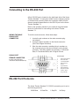
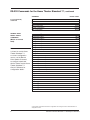
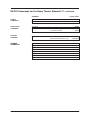
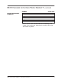
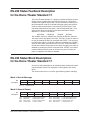
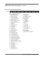
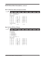
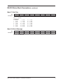
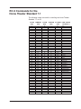
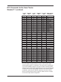
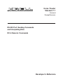
THE LEADER IN AUDIO ENGINEERING
Home Theater
Standard 7.1
Surround
Preamp/Processor
RS-232 Port: Sending Commands
and Interpreting Data
RC-5 Remote: Commands
Developer’s Reference
Home Theater Standard 7.1
Surround Preamp/Processor
Developer’s Reference
v 03.0
CONTACT
INFORMATION
Krell Industries, Inc.
45 Connair Road
Orange, CT 06477-3650 USA
TEL 203-799-9954
FAX 203-891-2028
E-MAIL [email protected]
WEBSITE http://www.krellonline.com
This product is manufactured in the United States of America. Krell® is a registered trademark of Krell
Industries, Inc., and is restricted for use by Krell Industries, Inc., its subsidiaries, and authorized agents.
All other trademarks and trade names are registered to their respective companies.
© 2002 by Krell Industries, Inc. All rights reserved
P/N 306016
Overview
This document is designed for application developers who want
to control the Home Theater Standard 7.1 using an external
computer-based device. The document contains five sections:
1
Connecting to the RS-232 Port, including the
RS-232 connector diagram, and RS-232 Port
Protocols, on page 4
2
RS-232 Commands, on page 5
3
RS-232 Status Feedback Description, on page 11
4
RS-232 Status Block Descriptions, showing how the
Home Theater Standard 7.1 reports operational
status, on page 11
RC-5 Commands, describing the codes used for
controlling the Home Theater Standard 7.1 via IR,
on page 18.
5
Krell Home Theater Standard 7.1 Developer’s Reference
3
Connecting to the RS-232 Port
A 9-pin RS-232 port is located on the right-hand side of the Home
Theater Standard 7.1 back panel. Make sure the clamping screws
(or thumbscrews) securely fasten the connection cable from the
external computer-based device to the RS-232 port on the Home
Theater Standard 7.1.
Refer to the operating manual of your external computer-based
device for instructions on connecting to the Home Theater
Standard 7.1.
WIRING THE MALE
RS-232 PORT
CONNECTOR
To wire the male connector, follow these steps:
1. Locate the pin numbers on the male connector plug
(not shown).
2. Locate the pinout numbers on the female connector.
(See Pinout Signal list below).
3. Wire the male connector, matching the pin numbers on
the connector plug to the pinout numbers on the female
connector. Only three signals are necessary: 2=Received
Data, 3=Transmitted Data, and 5=Signal Ground.
RS-232 PORT
FEMALE CONNECTOR
5 4 3 2 1
Pinout Signal
1
2
3
4
(located on the back panel
of the Home Theater Standard 7.1)
5
6
7
8
9
9 8 7 6
Data Carrier Detect
Received Data
Transmitted Data
Data Terminal
Ready
Signal Ground
Data Set Ready
Request to Send
Clear to Send
Ring Indicator
RS-232 Port Protocols
The Home Theater Standard 7.1 RS-232 connection port is set to
the following protocols:
9600 Baud
4
8 Data Bits
1 Stop Bit
No Parity
Krell Home Theater Standard 7.1 Developer’s Reference
RS-232 Commands for the Home Theater Standard 7.1
COMMAND
RS-232 CODE
MENU
COMMANDS
Up
Down
Left
Right
Menu
Enter
Previous
UPZ
DWNZ
LFTZ
RGTZ
MENZ
ENTZ
PRVZ
AUTO-STATUS
COMMANDS
Disable Auto Status
Enable Auto Status
Get Status
ASTDZ
ASTEZ
STAZ
GENERAL
DEVICE SELECT
COMMANDS
DVD Device Select1
LD Device Select1
Satellite Device Select1
VCR Device Select1
TV Device Select1
CD Device Select1
Tuner Device Select1
Aux1 Device Select1
Aux 2 Device Select1
Tape Monitor Select1
LEVEL
COMMANDS
Up
Down
Main Speaker Volume
Zone 2 Speaker Volume
Center Trim Select
Surround Trim Select
Sub Trim Select
Center Speaker Trim
Surround Speaker Trim
Back Speaker Trim
Subwoofer Trim
Current Zone Balance Select
Balance
Zone 2 Balance
DVDZ
LDZ
SATZ
VCRZ
TVZ
CDZ
TUNZ
AU1Z
AU2Z
TPZ
000 - 152
000 - 152
then use UPZ and DWNZ
must be on main zone
then use UPZ and DWNZ
send twice for Back Trim Select
must be on main zone
then use UPZ and DWNZ
must be on main zone
000 - 020, sets -10 to +10 dB
000 - 020, sets -10 to +10 dB
000 - 020, sets -10 to +10 dB
000 - 020, sets -10 to +10 dB
then use UPZ and DWNZ
000 -026, sets right off, left +6,
through right +6, left off 1/2 dB steps
then use UPZ and DWNZ
UPZ
DWNZ
XXXMVLZ
XXXRVLZ
ICVLZ
IRVLZ
ISUBZ
XXXCVLZ
XXXSRLZ
XXXBVLZ
XXXSVLZ
IBALZ
XXBALZ
BRLZ
1 The General Device Select Command is the best choice for normal operation: It always functions on the
currently selected zone and engages any configurations set through the Home Theater Standard 7.1 menu.
Krell Home Theater Standard 7.1 Developer’s Reference
5
RS-232 Commands for the Home Theater Standard 7.1, continued
COMMAND
RS-232 CODE
Level Commands,
continued
Mute Current Zone
Mute Main Zone
Mute Zone 2
Night Compression
Normal Compression
Max Compression
GENERIC ZONE
DIRECT SELECT
COMMANDS
7.1 Input select2
Analog Audio Input-12
Analog Audio Input-22
Analog Audio Input-32
Analog Audio Input-42
Analog Audio Input-52
Analog Audio Input-62
Analog Audio Input-72
Analog Balanced Input2
Analog Tape Select2
Analog VCR Select2
Coax-1 Digital Audio Input Select2
Coax-2 Digital Audio Input Select2
Coax-3 Digital Audio Input Select2
Coax-4 Digital Audio Input Select2
Coax-5 Digital Audio Input Select2
Coax-6 Digital Audio Input Select2
Optical-1 Digital Audio Input Select2
Optical-2 Digital Audio Input Select2
Component Video-12
Component Video-22
Composite Video-12
Composite Video-22
Composite Video-32
Composite Video-42
S-Video-12
S-Video-22
S-Video-32
S-Video-42
(Works on current
zone)
Note
It is best to use the Home
Theater Standard 7.1
on-screen configuration
menus, not the Generic
Direct Select Command,
to configure a particular
device. Please see the Home
Theater Standard 7.1
Owner’s Reference for
configuration details.
MUTZ
MUTMZ
MUTRZ
NTCZ
NMCZ
MXCZ
AMCZ
AS1Z
AS2Z
AS3Z
AS4Z
AS5Z
AS6Z
AS7Z
AB1Z
ATPAZ
AVCAZ
CO1Z
CO2Z
CO3Z
CO4Z
CO5Z
CO6Z
OPT1Z
OPT2Z
CM1Z
CM2Z
CS1Z
CS2Z
CS3Z
CS4Z
SV1Z
SV2Z
SV3Z
SV4Z
2 Direct Select Commands override the configurations set through the Home Theater Standard 7.1
configuration menus.
6
Krell Home Theater Standard 7.1 Developer’s Reference
RS-232 Commands for the Home Theater Standard 7.1, continued
COMMAND
MAIN ZONE
DIRECT SELECT
COMMANDS
(Main zone
must be on)
ZONE 2 DIRECT
SELECT COMMANDS
Note
Use Zone 2 Direct Select
Commands only when both
zones are on.
RS-232 CODE
Main Analog Audio Input-1
Main Analog Audio Input-2
Main Analog Audio Input-3
Main Analog Audio Input-4
Main Analog Audio Input-5
Main Analog Audio Input-6
Main Analog Audio Input-7
Main Analog Balanced Input
Main Analog Tape Select
Main Analog VCR Select
Main Aux1 Device Select
Main Aux2 Device Select
Main CD Device Select
Main DVD Device Select
Main LD Device Select
Main Satellite Device Select
Main Tape Device Select
Main Tuner Device Select
Main TV Device Select
Main VCR Device Select
Zone
Zone
Zone
Zone
Zone
Zone
Zone
Zone
Zone
Zone
Zone
Zone
Zone
Zone
Zone
Zone
Zone
Zone
Zone
Zone
2 Analog Audio Input-13
2 Analog Audio Input-23
2 Analog Audio Input-33
2 Analog Audio Input-43
2 Analog Audio Input-53
2 Analog Audio Input-63
2 Analog Audio Input-73
2 Analog Balanced Input3 AB1RZ
2 Analog Tape Select3
2 Analog VCR Select3
2 Aux1
2 Aux2
2 CD
2 DVD
2 LD
2 Satellite
2 Tape
2 Tuner
2 TV
2 VCR
AS1MZ
AS2MZ
AS3MZ
AS4MZ
AS5MZ
AS6MZ
AS7MZ
AB1MZ
TPAMZ
VCAMZ
AU1MZ
AU2MZ
CDMZ
DVDMZ
LDMZ
SATMZ
TPMZ
TUNMZ
TVMZ
VCRMZ
AS1RZ
AS2RZ
AS3RZ
AS4RZ
AS5RZ
AS6RZ
AS7RZ
TPARZ
VCARZ
AU1RZ
AU2RZ
CDRZ
DVDRZ
LDRZ
SATRZ
TPRZ
TUNRZ
TVRZ
VCRRZ
3 If only zone 2 is on, use instead the Generic Zone Direct Select Commands, on page 6.
Krell Home Theater Standard 7.1 Developer’s Reference
7
RS-232 Commands for the Home Theater Standard 7.1, continued
COMMAND
POWER
COMMANDS
Power On
Power Off
ZONE SELECT
COMMANDS
Main Zone
Zone 2
ROOM EQ
COMMAND
Room EQ Select
TRIGGER
COMMANDS
Trigger-1
Trigger-1
Trigger-2
Trigger-2
Trigger-3
Trigger-3
Trigger-4
Trigger-4
8
RS-232 CODE
1PWRZ
0PWRZ
MANZ
Zone 2 power toggle
if main zone Is OFF
XXX = 000-004 (000 = OFF)
(001-004 selects memory 1-4)
OFF
ON
OFF
ON
OFF
ON
OFF
ON
REMZ
XXXEQMZ
0TR1Z
1TRIZ
0TR2Z
1TR2Z
0TR3Z
1TR3Z
0TR4Z
1TR4Z
Krell Home Theater Standard 7.1 Developer’s Reference
RS-232 Commands for the Home Theater Standard 7.1, continued
COMMAND
DECODE MODE SELECT
COMMANDS
Mode 1
Mode 2
Prologic
Stereo
Preamp
THX
Audio Decode Set Mode
RS-232 CODE
000 - 038, sets mode*
MS1Z
MS2Z
MVZ
STZ
PAZ
THXZ
XXXMODZ
* Refer to the list of audio decode modes and corresponding codes
on page 10 to set the mode. Modes that do not apply to the current
input stream are ignored.
Krell Home Theater Standard 7.1 Developer’s Reference
9
RS-232 Commands for the Home Theater Standard 7.1, continued
Audio decode modes
and corresponding codes
10
AUDIO DECODE MODE
CODE
Dolby Digital 5.1
Dolby Digital 5.1 + THX
Dolby Digital 5.1 + THX EX
AC3 2/0 Stereo Mode (Pass Mode)
AC3 2/0 Pro-Logic II Movie Mode
AC3 2/0 Pro-Logic II Music Mode
AC3 2/0 Pro-Logic II Matrix Mode
AC3 2/0 Pro-Logic II Emulation Mode
AC3 2/0 Pro-Logic II Movie +THX Mode
AC3 2/0 Pro-Logic II Emulation+THX Mode
DTS 5.1 Music
DTS 5.1 Movie
DTS 5.1 Matrix
DTS 5.1 Movie + THX
DTS 5.1 Matrix + THX
DTS 6.1 Discrete
DTS 6.1 Discrete + THX
DTS 5.1 Force
Stereo Mode (Pass Mode)
Pro-Logic II Movie Mode
Pro-Logic II Music Mode
Pro-Logic II Matrix Mode
Pro-Logic II Emulation Mode
Pro-Logic II Movie + THX Mode
Pro-Logic II Emulation + THX
DTS Neo:6 Cinema 6 Mode
DTS Neo:6 Music Mode
DTS Neo:6 Cinema 6 + THX Mode
Party Mode
General Admission Mode
Front Row Mode
On Stage Mode
Enhanced Stereo Mode
Orchestra Mode
Mezzanine Mode
Full Range + Sub Mode
Monophonic Mode
24/96 Decode Mode
000
001
002
003
004
005
006
007
008
009
010
011
012
013
014
015
016
017
018
019
020
021
022
023
024
025
026
027
028
029
030
031
032
033
034
035
036
038
Krell Home Theater Standard 7.1
RS-232 Status Feedback Description
for the Home Theater Standard 7.1
The Home Theater Standard 7.1 reports its operational status by transmitting a block of status data via the RS-232 connector. The block is
configured as eighteen 8-bit words. The first and last word always contains hexadecimal code 55 to facilitate message framing and synchronization. When the data block is sent through an RS-232 port, each
8-bit word transmitted will also have 1 stop bit associated with it. The
exact RS-232 protocol settings for both status and Home Theater
Standard 7.1 control are as follows:
9600 Baud
8 Data Bits
1 Stop Bit
No Parity
The feedback system is available only through the RS-232 connector.
The status can be activated in two ways. The first is to ask for status to
be sent by sending the RS-232 command code "STAZ". The second is
to enable auto status by sending the RS-232 command code "ASTEZ".
Once the auto status command is sent, the Home Theater Standard 7.1
will transmit a status block whenever the status changes. Auto status is
disabled by sending the RS-232 command code "ASTDZ". Auto status
remains enabled until AC power is removed or turned off. When AC
power is reapplied, auto status is disabled.
RS-232 Status Block Descriptions
for the Home Theater Standard 7.1
All numeric values described in the following charts are decimal values
unless otherwise noted. The description of the eighteen 8-bit words
follow.
The values marked
Reserved
must be ignored during pattern matching.
Word 1: Start of Message
Bit
7
0
Description
6
1
Bit 7 – 0:
5
0
4
1
3
0
2
1
1
0
0
1
Hexadecimal 55
Word 2: General Status I
7
6
5
4
3
2
1
0
System Mute
User Mute
Zone 2 Mute
Current Zone
Input Trigger
Zone 2 Only
Zone 2 Power
Main Power
Bit
Description
Bit
Bit
Bit
Bit
7:
6:
5:
4:
System Mute
Main Mute
Zone 2 Mute
Current Zone
1
1
1
1
=
=
=
=
Internal mute is active
Main mute is active
Zone 2 mute is active
Zone 2 is active
Krell Home Theater Standard 7.1 Developer’s Reference
Bit
Bit
Bit
Bit
3:
2:
1:
0:
Input Trigger
Zone 2 Only
Zone 2 Power
Main Power
1
1
1
1
=
=
=
=
12V input trigger is active
Only Zone 2 power is on
Zone 2 power is on
Main power is on
11
RS-232 Status Block Descriptions, continued
Word 3: General Status II
Bit
Description
7
6
5
4
3
2
1
0
Menu Mode
Auto Status
Enabled
PLL Locked
Trigger 4 On
Trigger 3 On
Trigger 2 On
Trigger 1 On
DSP Running
Bit
Bit
Bit
Bit
Bit
Bit
Bit
Bit
7:
6:
5:
4:
3:
2:
1:
0:
Menu mode
Auto Status
PLL Locked
Trigger 4 On
Trigger 3 On
Trigger 2 On
Trigger 1 On
DSP Running
1
1
1
1
1
1
1
1
= Menu mode is active
= Auto status enabled
= PLL is locked (valid digital input signal detected)
= Trigger 4 is on
= Trigger 3 is on
= Trigger 2 is on
= Trigger 1 is on
= DSPs are not reset
Word 4: Current Device
Bit
Description
7
6
5
4
3
2
1
0
Z2 CD3
Z2 CD2
Z2 CD1
Z2 CD0
MN CD3
MN CD2
MN CD1
MN CD0
Bits 7 – 4: Zone 2 Current Device
Bits 3 – 0: Main Zone Current Device
Devices
0 DVD
1 LD
2 SAT
3 VCR
4 TV
5
6
7
8
9
CD
TUNER
AUX 1
AUX 2
TAPE
Word 5: Volume
Bit
Description
7
6
5
4
3
2
1
0
V0L 7
V0L 6
V0L 5
V0L 4
V0L 3
V0L 2
V0L 1
V0L 0
Bit 7 – 0:
Current Volume setting 0 – 152
Word 6: Zone 2 Volume
Bit
Description
7
6
5
4
3
2
1
0
VOL 7
VOL 6
VOL 5
VOL 4
VOL 3
VOL 2
VOL 1
VOL 0
Bit 7 – 0:
Current Zone 2 Volume setting 0 – 152
Word 7: Video Input
Bit
Description
7
6
5
4
3
2
1
0
VID IN 7
VID IN 6
VID IN 5
VID IN 4
VID IN 3
VID IN 2
VID IN 1
VID IN 0
Bit 7 – 0:
Current Video Input
Video Inputs
1 S-Video 1
2 S-Video 2
3 S-Video 3
4 S-Video 4
5 Component Video 1
6 Component Video 2
12
7
8
9
10
11
Reserved
Composite
Composite
Composite
Composite
Video
Video
Video
Video
1
2
3
4
Krell Home Theater Standard 7.1 Developer’s Reference
RS-232 Status Block Descriptions, continued
Word 8: Main Zone Audio Input
Bit
Description
7
MN AUD
IN 7
Bit 7 – 0:
6
MN AUD
IN 6
5
MN AUD
IN 5
4
MN AUD
IN 4
3
MN AUD
IN 3
2
MN AUD
IN 2
1
MN AUD
IN 1
0
MN AUD
IN 0
Main Zone Audio Input
Audio Inputs
1 Digital: COAX 1
2 Digital: COAX 2
3 Digital: COAX 3
4 Digital: COAX 4
5 Digital: COAX 5
6 Digital: COAX 6
7 Digital: Optical 1
8 Digital: Optical 2
9 Analog: B1
10
11
12
13
14
15
16
17
18
Analog: S1
Analog: S2
Analog: S3
Analog: S4
Analog: S5
Analog: S6
Analog: S7
Analog: Tape
Analog: VCR
Word 9: Zone 2 Audio Input
Bit
Description
7
6
5
4
3
2
1
0
Z2 AUD IN 7
Z2 AUD IN 6
Z2 AUD IN 5
Z2 AUD IN 4
Z2 AUD IN 3
Z2 AUD IN 2
Z2 AUD IN 1
Z2 AUD IN 0
Bit 7 – 0:
Zone 2 Audio Input
Audio Inputs
1 Digital: COAX 1
2 Digital: COAX 2
3 Digital: COAX 3
4 Digital: COAX 4
5 Digital: COAX 5
6 Digital: COAX 6
7 Digital: Optical 1
8 Digital: Optical 2
9 Analog: B1
10
11
12
13
14
15
16
17
18
Analog: S1
Analog: S2
Analog: S3
Analog: S4
Analog: S5
Analog: S6
Analog: S7
Analog: Tape
Analog: VCR
Word 10: Loudspeakers / Current Audio Stream
Bit
Description
7
Back
Enabled
Bit 7:
Bit 6:
Bit 5:
Bit 4:
Bits 3–0:
6
Sub
Enabled
Back Enabled
Sub Enabled
Surround Enabled
Center Enabled
Current Input
Stream Mode
Input Stream Modes
1 PCM
2 Dolby Digital 2.0
3 Dolby Digital 5.1
4 DTS 5.1
5 24-bit, 96 KHz PCM
6 PCM Digital Input
5
Surround
Enabled
1
1
1
1
7
8
9
10
11
12
=
=
=
=
4
Center
Enabled
3
2
1
0
Input Stream 3 Input Stream 2 Input Stream 1 Input Stream 0
Back loudspeaker(s) is(are) enabled
Subwoofer is enabled
Surround loudspeakers are enabled
Center loudspeaker is enabled
PCM Analog Input
Dolby Digital X/Y
7.1 (8 Channel discrete)
DTS 6.1 ES Matrix
DTS 6.1 ES Discrete
DTS 6.1 ES Matrix & Discrete
Krell Home Theater Standard 7.1 Developer’s Reference
13
RS-232 Status Block Descriptions, continued
Word 11: Current Audio Decode Modes
Bit
Description
7
6
5
4
3
2
1
0
CAD 7
CAD 6
CAD 5
CAD 4
CAD 3
CAD 2
CAD 1
CAD 0
Bit 7 – 0:
14
Current Audio Decode Modes
Analog and PCM Decode Modes
1 Stereo Mode (Pass Mode)
2 Pro-Logic II Movie Mode
3 Pro-Logic II Music Mode
4 Pro-Logic II Matrix Mode
5 Pro-Logic II Emulation Mode
6 Pro-Logic II Movie + THX Mode
7 Multichannel Input Mode
8 Pro-Logic II Emulation + THX Mode
9 DTS Neo:6 Cinema 6 Mode
11 DTS Neo:6 Music Mode
12 DTS Neo:6 Cinema 6 + THX Mode
13 Noise Mode
14 Classical Mode
15 General Admission Mode
16 Front Row Mode
17 On Stage Mode
18 Enhanced Stereo Mode
19 Orchestra Mode
20 Mezzanine Mode
21 Full Range + Sub Mode
22 Monophonic Mode
23 Analog-only Preamp Mode
Dolby AC3, 5/1 Modes
47 Dolby Digital 5.1
48 Dolby Digital 5.1 + THX
49 Dolby Digital 5.1 + THX EX
Dolby AC3, 2/0 Modes
24 Stereo Mode (Pass Mode)
25 Pro-Logic II Movie Mode
26 Pro-Logic II Music Mode
27 Pro-Logic II Matrix Mode
28 Pro-Logic II Emulation Mode
29 Pro-Logic II Movie + THX Mode
30 Pro-Logic II Matrix + THX Mode
31 Pro-Logic II Emulation + THX Mode
32 was DTS Neo:6 Cinema 6 Mode
33 was DTS Neo:6 Cinema 5 Mode
34 was DTS Neo:6 Music Mode
35 was DTS Neo:6 Cinema 6 + THX Mode
36 was DTS Neo:6 Cinema 5 + THX Mode
37 Party Mode
38 General Admission Mode
39 Front Row Mode
40 On Stage Mode
41 Enhanced Stereo Mode
42 Orchestra Mode
43 Mezzanine Mode
44 Full Range + Sub Mode
45 Monophonic Mode
46 Analog-only Preamp Mode
7.1 (8 Channel Discrete Input) Modes
7 7.1
Dolby AC3, X/Y Modes
65 Dolby Digital 1+1
66 Dolby Digital 1/0
67 Dolby Digital 3/0
68 Dolby Digital 2/1
69 Dolby Digital 3/1
70 Dolby Digital 2/2
DTS Modes
50 DTS 5.1
51 DTS 5.1
52 DTS 5.1
53 DTS 5.1
54 DTS 5.1
55 DTS 6.1
56 DTS 6.1
57 DTS 5.1
Movie
Matrix
Movie + THX
Music
Matrix + THX
Discrete
Discrete + THX
Force
24-bit, 96 KHz Modes
10 PCM 24-bit, 96 KHz
Krell Home Theater Standard 7.1 Developer’s Reference
RS-232 Status Block Descriptions, continued
Word 12: Main Zone Balance/Compression Mode
Bit
Description
7
6
5
4
3
2
1
0
Reserved
CMode 1
CMode 0
BAL 4
BAL 3
BAL 2
BAL 1
BAL 0
Bits 4 - 0:
Bits 5 – 6:
Balance Setting 0 – 26
Compression Mode
Balance Settings
0 Right Off
1 Left
+6
2 Left +5.5
3 Left +5.0
4 Left +4.5
5 Left +4.0
6 Left +3.5
7 Left +3.0
8 Left +2.5
9
10
11
12
13
14
15
16
17
Compression Modes
1 Max
2
Left
+2.0
Left
+1.5
Left
+1.0
Left
+0.5
Centered 0
Right +0.5
Right +1.0
Right +1.5
Right +2.0
Normal
18
19
20
21
22
23
24
25
26
Right
Right
Right
Right
Right
Right
Right
Right
Left
3
Night
+2.5
+3.0
+3.5
+4.0
+4.5
+5.0
+5.5
+6.0
Off
Word 13: Room EQ/Zone 2 Balance
Bit
Description
7
6
5
4
3
2
1
0
Room EQ 2
Room EQ 1
Room EQ 0
BAL 4
BAL 3
BAL 2
BAL 1
BAL 0
Bits 7 – 5: Room EQ Setting
Room EQ Setting
0 Room EQ OFF
1 Room EQ Memory
2 Room EQ Memory
3 Room EQ Memory
4 Room EQ Memory
Bits 4 - 0:
1
2
3
4
Balance Setting 0 – 26
Balance Settings
0 Right Off
1 Left
+6
2 Left +5.5
3 Left +5.0
4 Left +4.5
5 Left +4.0
6 Left +3.5
7 Left +3.0
8 Left +2.5
9
10
11
12
13
14
15
16
17
Left
+2.0
Left
+1.5
Left
+1.0
Left
+0.5
Centered 0
Right +0.5
Right +1.0
Right +1.5
Right +2.0
Krell Home Theater Standard 7.1 Developer’s Reference
18
19
20
21
22
23
24
25
26
Right
Right
Right
Right
Right
Right
Right
Right
Left
+2.5
+3.0
+3.5
+4.0
+4.5
+5.0
+5.5
+6.0
Off
15
RS-232 Status Block Descriptions, continued
Word 14: Center Trim
Bit
Description
7
6
5
4
3
2
1
0
Reserved
Reserved
Reserved
CT 4
CT 3
CT 2
CT 1
CT 0
4
RT 4
3
RT 3
2
RT 2
1
RT 1
0
RT 0
Bits 4 – 0:
Center Trim
Trim Settings
0 -10 dB
1 -9 dB
2 -8 dB
3 -7 dB
4 -6 dB
5 -5 dB
6 -4 dB
7 -3 dB
8 -2 dB
9 -1 dB
10
0
11 +1
12 +2
13 +3
14 +4
15 +5
16 +6
17 +7
18 +8
19 +9
20 +10
dB
dB
dB
dB
dB
dB
dB
dB
dB
dB
dB
Word 15: Surround Trim
Bit
Description
7
Mode 1/2
LED Status
6
Reserved
5
Reserved
Bit 7: Mode 1/2 LED Status 1 = Mode 1 LED is On, 0 = Mode 2 LED is On
Bits 4 – 0: Surround Trim
Trim Settings
0 -10 dB
1 -9 dB
2 -8 dB
3 -7 dB
4 -6 dB
5 -5 dB
6 -4 dB
7 -3 dB
8 -2 dB
9 -1 dB
10 0 dB
11 +1 dB
12 +2 dB
13 +3 dB
14 +4
15 +5
16 +6
17 +7
18 +8
19 +9
20 +10
dB
dB
dB
dB
dB
dB
dB
Word 16: Back Trim
Bit
Description
7
6
5
4
3
2
1
0
Reserved
Reserved
Reserved
BT 4
BT 3
BT 2
BT 1
BT 0
Bits 4 – 0: Back Trim
Trim Settings
0 -10 dB
1 -9 dB
2 -8 dB
3 -7 dB
4 -6 dB
5 -5 dB
6 -4 dB
16
7 -3 dB
8 -2 dB
9 -1 dB
10 0 dB
11 +1 dB
12 +2 dB
13 +3 dB
14 +4
15 +5
16 +6
17 +7
18 +8
19 +9
20 +10
dB
dB
dB
dB
dB
dB
dB
Krell Home Theater Standard 7.1 Developer’s Reference
RS-232 Status Block Descriptions, continued
Word 17: Sub Trim
Bit
Description
7
6
5
4
3
2
1
0
Reserved
Reserved
Reserved
ST 4
ST 3
ST 2
ST 1
ST 0
Bits 4 – 0: Sub Trim
Trim Settings
0 -10 dB
1 -9 dB
2 -8 dB
3 -7 dB
4 -6 dB
5 -5 dB
6 -4 dB
7 -3 dB
8 -2 dB
9 -1 dB
10 0 dB
11 +1 dB
12 +2 dB
13 +3 dB
14 +4
15 +5
16 +6
17 +7
18 +8
19 +9
20 +10
dB
dB
dB
dB
dB
dB
dB
Word 18: End of Message
Bit
7
6
5
4
3
2
1
0
Description
0
1
0
1
0
1
0
1
Bit 7 – 0:
Hexadecimal 55
Krell Home Theater Standard 7.1 Developer’s Reference
17
RC-5 Commands for the
Home Theater Standard 7.1
The following codes are used for controlling the Home Theater
Standard 7.1 via IR.
SYSTEM
(HEX)
1C
1C
1C
1C
1C
1C
1C
1C
1C
1C
1C
1C
1C
1C
1C
1C
1C
1C
1C
1C
1C
1C
1C
1C
1C
1C
1C
1C
1C
1C
1C
1C
1C
1C
1C
1C
1C
1C
1C
1C
1C
1C
1C
1C
19
19
19
19
19
18
COMMAND
(HEX)
1
2
6
7
B
C
D
E
F
10
11
12
19
1A
1B
1C
1D
1E
1F
20
21
22
23
24
27
28
29
2A
2B
2C
2D
2E
2F
30
33
35
37
38
39
3A
3B
3C
3D
3E
0
1
2
3
4
SYSTEM
(DEC)
28
28
28
28
28
28
28
28
28
28
28
28
28
28
28
28
28
28
28
28
28
28
28
28
28
28
28
28
28
28
28
28
28
28
28
28
28
28
28
28
28
28
28
28
25
25
25
25
25
COMMAND RC5 WORD HOME THEATER
(DEC)
(HEX)
STANDARD 7.1
1
2
6
7
11
12
13
14
15
16
17
18
25
26
27
28
29
30
31
32
33
34
35
36
39
40
41
42
43
44
45
46
47
48
51
53
55
56
57
58
59
60
61
62
0
1
2
3
4
3701
3702
3706
3707
370B
370C
370D
370E
370F
3710
3711
3712
3719
371A
371B
371C
371D
371E
371F
3720
3721
3722
3723
3724
3727
3728
3729
372A
372B
372C
372D
372E
372F
3730
3733
3735
3737
3738
3739
373A
373B
373C
373D
373E
3640
3641
3642
3643
3644
SUB
REAR
CENTER
MUTE
DOWN
MENU
RIGHT
ENTER
LEFT
TAPE
UP
PREV
7.1 INPUT
BALANCE
B1
S1
S2
S3
S4
S5
COAX1
COAX2
OPT1
OPT2
TAPE ON
TAPE OFF
S-VIDEO1
S-VIDEO2
S-VIDEO3
S-VIDEO4
COMPOSITE1
COMPOSITE2
COMPOSITE3
COMPOSITE4
MUSIC1
STEREO
VOL ZERO
PWR ON
PWR OFF
MUTE ON
MUTE OFF
VOL +10
VOL -10
PROLOGIC
MUSIC2
DVD
LD
SAT
VCR
Krell Home Theater Standard 7.1 Developer’s Reference
RC-5 Commands for the Home Theater
Standard 7.1, continued
SYSTEM
(HEX)
19
19
19
19
19
19
19
19
19
19
19
19
19
19
19
19
19
19
19
19
19
19
19
19
19
19
19
19
19
1C
1C
1C
1C
1C
19
19
19
19
19
19
19
19
19
19
19
COMMAND
(HEX)
5
6
7
8
9
A
B
C
D
E
10
11
12
13
13
15
16
17
18
19
1A
1B
1C
1D
1E
1F
20
21
22
14
15
16
17
18
30
31
32
33
34
35
36
37
38
39
3A
SYSTEM
(DEC)
25
25
25
25
25
25
25
25
25
25
25
25
25
25
25
25
25
25
25
25
25
25
25
25
25
25
25
25
25
28
28
28
28
28
25
25
25
25
25
25
25
25
25
25
25
COMMAND RC5 WORD HOME THEATER
(DEC)
(HEX)
STANDARD 7.1
5
6
7
8
9
10
11
12
13
14
16
17
18
19
19
21
22
23
24
25
26
27
28
29
30
31
32
33
34
20
21
22
23
24
48
49
50
51
52
53
54
55
56
57
58
3645
3646
3647
3648
3649
364A
364B
364C
364D
364E
3650
3651
3652
3653
3654
3655
3656
3657
3658
3659
365A
365B
365C
365D
365E
365F
3668
3669
366A
3714
3715
3716
3717
3718
3670
3671
3672
3673
3674
3675
3676
3677
3678
3679
367A
TV
CD
TUNER
AUX1
AUX2
MAIN ZONE
ZONE 2
USER
VCR INPUT
TAPE INPUT
COMPONENT1
COMPONENT2
COAX3
COAX4
COAX5
COAX6
TRIGGER1 ON
TRIGGER1 OFF
TRIGGER2 ON
TRIGGER2 OFF
TRIGGER3 ON
TRIGGER3 OFF
TRIGGER4 ON
TRIGGER4 OFF
Z2 PWR ON
Z2 PWR OFF
MAX DYNR
NIGHT DYNR
NORM DYNR
EQ OFF
EQ MEM1
EQ MEM2
EQ MEM3
EQ MEM4
DIGIT 0
DIGIT 1
DIGIT 2
DIGIT 3
DIGIT 4
DIGIT 5
DIGIT 6
DIGIT 7
DIGIT 8
DIGIT 9
SET MODE**
**The SET MODE command allows the user to set a specific audio
decode mode using RC 5 commands. The code is set by sending the
unit the SET MODE command, then the two DIGIT commands which
define the mode. These three commands must occur in sequence; any
command sent after the SET MODE command, other than the DIGIT
commands, causes the SET MODE sequence to be reset. Refer to
the list of audio decode modes on page 20. Modes that do not apply
to the current input stream are ignored.
Krell Home Theater Standard 7.1 Developer’s Reference
19
RC-5 Commands for the Home Theater Standard 7.1, continued
Audio decode modes
and corresponding codes
20
AUDIO DECODE MODE
CODE
Dolby Digital 5.1
Dolby Digital 5.1 + THX
Dolby Digital 5.1 + THX EX
AC3 2/0 Stereo Mode (Pass Mode)
AC3 2/0 Pro-Logic II Movie Mode
AC3 2/0 Pro-Logic II Music Mode
AC3 2/0 Pro-Logic II Matrix Mode
AC3 2/0 Pro-Logic II Emulation Mode
AC3 2/0 Pro-Logic II Movie +THX Mode
AC3 2/0 Pro-Logic II Emulation+THX Mode
DTS 5.1 Music
DTS 5.1 Movie
DTS 5.1 Matrix
DTS 5.1 Movie + THX
DTS 5.1 Matrix + THX
DTS 6.1 Discrete
DTS 6.1 Discrete + THX
DTS 5.1 Force
Stereo Mode (Pass Mode)
Pro-Logic II Movie Mode
Pro-Logic II Music Mode
Pro-Logic II Matrix Mode
Pro-Logic II Emulation Mode
Pro-Logic II Movie + THX Mode
Pro-Logic II Emulation + THX
DTS Neo:6 Cinema 6 Mode
DTS Neo:6 Music Mode
DTS Neo:6 Cinema 6 + THX Mode
Party Mode
General Admission Mode
Front Row Mode
On Stage Mode
Enhanced Stereo Mode
Orchestra Mode
Mezzanine Mode
Full Range + Sub Mode
Monophonic Mode
24/96 Decode Mode
00
01
02
03
04
05
06
07
08
09
10
11
12
13
14
15
16
17
18
19
20
21
22
23
24
25
26
27
28
29
30
31
32
33
34
35
36
38
Krell Home Theater Standard 7.1