1
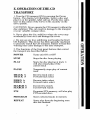
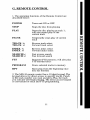
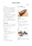
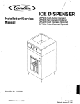
MD-10 OWNER’S REFERENCE
A. INTRODUCTION
TCrOngratulations
on yourand
purchase
oftothethe
MD-10
CD
anscription turntable
welcome
KRELL
family oF audio components.Youha.vejoined a select
groupof listeners whoenjoy only tlae tlnest in music
reproduction.
Weare dedicated to the~ developmentof technologically
advancedcomponentstor the reproduction o.f digat~ly
recorded music and continuing the Krell tradition ot
uncompromisedperformance through leading-edge technology.
This Owner’sReferenceis divided into several sections,
each designed to performa different function. Basic
installation, operation and a Question and Answersection
are included, where answers to common
questions are
provided. Shouldyou have any questions or suggestigns,
i~lease feel free to contact yourauthorizeddealer or tlae
KRELL
staff for assistance.
In the unlikely, event that your.MD-1.0
should require
serviceyouwill be pleased~to l~n~owtlaat it is backedby a
c.omprehensiveCustomerbatistaction policy and one of
tlae mostadvancedservice facilities in the industry, bor
detailed informationon the terms and conditions of service please consult your warra..nty registration card or
your authorized KRELL
Distributor.
2
B. TABLE OF CONTENTS
3
UNPACKING AND ASSEMBLY
4
DUST COVER INSTALLATION
6
BASIC INSTALLATION AND CONNECTIONS
9
OPERATION OF THE CD TRANSPORT
11
REMOTE CONTROL
12
TRACK AND FTS PROGRAMMING
15
MAINTENANCE
16
QUESTIONS AND ANSWERS
18
SPECIFICATIONS
19
WARRANTYAND SERVICE INFORMATION
C. UNPACKING AND ASSEMBLY
1. Openthe box and removethe top layer of protective
foam. The following items will nowbe visible:
1 Dust Coverencased in a protective sleeve
1 CDStabilizer
1 ACpower cord
1 MD-10RC Remote Control
1 Packet containing the Owner’sReference and warranty
card
NOTE:
If any of these items are not included, please
contact your authorized dealer immediatelyfor assistance.
2. Removethe layer of foamcontaining these items and
set it aside for later use. Carefully removethe MD-10
from its box and removethe protective plastic wrap.
NOTE:
Save all packing mate.rials. If you must ship your
MD-10
in the future, repack the unit in its original pa,ckaging to preventtransit damage.If the unit is re.turned to
KRELL
for service, please send the cover and tlae remote
control unit.
CAUTION:
Do not removethe acrylic dust cover from its
protective sleeve at this time! This cover is extremely
~lelicate and ca.n be permanentlyscarred if mishandled.
Please follow tlae instructions providedin this Reference
for safe installation.
3
D. DUST COVER INSTALLATION
1. Lookingat the front of the MD-10,locate the two
black hinge block assemblies on the rear left and right
corners. (Refer to location diagram)
2. Locate the hinge pin on the back of each hinge block
assembly and pull them out gently until they are fully
extended.
t3h.
Openthe
flap
only on the protective sleeve and locate
e three
cover
pins.
4. Place the cover over the unit and insert the cover into
the hinge block assemblies with the cover in the ~
u~ri~ht ~osition. Makesure all three pins are in there
proper receptacles. Refer to location diagram on page 5.
5. Lockthe cover into the hinge blocks .by pushing the
pins into themuntil they are fully seated.
6. Gently pull the cover forward and let it go, allowing
the cover to slowly descend.
CAUTION:
Do not push the dust cover down. Its damping system allows a slow descent, and can be damagedif
force is applied.
7. Removethe protective sleeve.
4
MD-10
LOCATION
1 Dust cover
2 Hinge block
3 Adjustable suspension tower
4 Transport
5 Hinge pin
6 Cover pin
7 Bubblelevel
5
DIAGRAM
E. BASIC INSTALLATION AND
CONNECTIONS
1. Place the unit on a clean, level surface awayfrom
excessive heat, moist.ure or light. Ideally, the MD-10
should be placed on tlae top of an audio componentcat)inet or other "openair" rigid platform.
2. TheMD-10
may.be. placed in a cabinet. It will require.
17.0 inches of vertical clearance betweenthe bottomanti
top shelves for proper operation of the cover.
3. If. space is limited, the MD-10
can be operated without
its clust cover. Six inchesvertical clearanceis adequateto
allow convenientaccess to the disc transport area.
4. Thelocation of the unit should be within 2 meters of
the digital signal proeess0r~If longerdistanc.e is re_quired,
we recommend
using an AT&T
fi.~re optic clata linl~ o.r an
AES/EBU
balanced~lata.link, as tlaey are moresuitecl to
long distance runs.
--~
5. Onceyou have founda location for the unit, adjust the
transport’s a_djustable suspensiontowers to makethe
MD--10ssurffice level. A bubble level is conveniently
mountedin the black acrylic, tOl~ plate, allowingfor easy
level adjus.t.ment, Adjust eacla ot the four suspension
towers until the bublSlein the level is centered. Counter
clockwiserotation raises the towers and clockwiserotation lowers the towers.
NOTE:The adjusta.ble suspension towers are only for
fine a.djustment anti can not compensatefor gross surface
irregularities.
6. Connectthe ACpowercord to the back of the unit.
Oncethe powercord is secured, plug the cord into an AC
outlet.
7. Press the POWER
button on the front panel. The display will illuminate and the transport will nowbe active.
NOTE:While the MD-10has superb regulation and does
not require a dedicated ACcircuit, westrongly advise
against any. connectionsthrough extension cords or multiple ACa~laptors. High quality 15 ampgroundedAC
strips are acceptable.
6
8. Connectthe Digital Output from the MD-10to a Krell
Digital Processor or other compatibledigital-to-analog
audio processor.
The MD-10is compatible with industry standard Fibre
~O_[?tic, Coaxial RCA,AT&T
wide bandwidthFibre Optic
~1 type and AES/EBU
XLRoutput connectors.
NOTE:
Care should be taken in selecting the type of
cable used to lin.k the MD,10to your processor. We
recommend
botla the AT&T
Fibre Optic due to its superior bandwidthand signal isolation properties, and ttie
AES/EBU
format due to its higher voltage transmission
and noise rejection due to balancedformat.
CAUTION:
The MD-10is a CDTransport only. It is not
designed to connect directly to any preampor analog
signal processor.
The MD-10
is equipped with a sp.ecial terminatiop system called TimeSync.TimeSyncis a system that locks.
the clock betweenthe MD-10
and specific Krell digitalto-analog processors. This connection is labeled
SPECIAL
on the back of the MD-10.The termination is
via an AT&T
fibre optic cable only and is used in conjunction with any of-the other digital links like the AT&T
or AES/EBU.
NOTE:The TimeSync system can ~ be utilized with
certain Krell digitaI-to-analog converters and will not
workwith any other makeor model. Please consult your
dealer or the Krell staff for specific information.
NOTE:The TimeSyncoutput can not be used as an additional digital output.
TIMESYNC CONNECTION
The TimeSyncsystem is terminated via an AT&T
ST
fibre optic cable.
1. Connectthe AT&T
fibre optic cable to the termination
labeled SPECIAL
on the MD-10.Makesure the small
key at the top of the fibre optic cable is upright and fits
smoothlyinto the AT&T
receptacle, twist the collar
clockwiseto lock the cable in place.
2. Connectthe free end of the fibre optic cable to the
termination labeled TimeSync/Extclock on the back of
your Krell digital-to-analog converter.
7
3. Connect your digital interlink between the transport ,
and digital-to-analog converter, if not already connectecl.
4. Select a digital source and press the TimeSyncbutton
on the front of your digital-to- analo~ converter. The
corresponding led will-illuminate indicating the
TimeS-ync is locked. Should the TimeSync-LEDflash,
tlais meansthe TimeSyncclock has not locked and. requires, resetting. Select any other digital input.on tlae
digital-to-analog converter and then reselect the input,
you. wisla to use. The TimeSyncLEDwill now be steacly
and the clock will be locked.
F. OPERATIONOF THE CD
TRANSPORT
1. Turn the CDtransport ONby pressing the Power
b.utton., Thedisplay will illuminate. Select a disc an.d
place it on the spindl~e,label side up. Put the disc st.alfifizer on the center ot the CDso it fits securelyon tide
drive spindle.
CAUTIONS:
Never operate the CDtransport without the
disc stabilizer. This can result in damageto the transport
or your valuable compactdiscs.
b. Neverplace the disc stabilizer wherethe cover may
accidentally close on it and damagethe cover.
c. Donot use any disc stabilizing tool besides the Krell
CDStabilizer. Th.is device has been specially machin.ed
to precisely matcla the CDtransport. Failure to heedtlais
warningmaycause damageto the laser transport.
2. Thefunctions of the front panel buttons that control
the transport are described below.
POWER
Turns unit ONor OFF
STOP
Stops the disc from playing
PLAY
Starts the disc playingat. track 1;
will also restart play of tlae
current track
PAUSE
Tem.porarilystops play of current
track
TRACK I<
TRACK >1
Reversetrack select
Forwardtrack select
INDEX I<
INDEX >1
Reverse index select
Forwardindex select
SEARCHI<
SEARCH>l
Fast reverse search
Fast forward search
FTS
Programs FTSmemory;will also play
FTS-encodeddiscs
PROGRAM
Stores selected tracks in memory
REPEAT
Starts play from the beginning once
disc has finished
9
3. Select a track on the CDto play with the remotecontrol or via the front panel and press the Play button. The
music will nowbegan.
10
G.
REMOTE CONTROL
1. Theoperatingfunctions of the RemoteControlare
describei] below:
POWER
Turns unit ONor OFF
STOP
Stops the disc from playing
PLAY
Starts the disc playingat. track 1;
will also restart pray of the
current track
PAUSE
Tem.porarilystops play of current
track
TRACK I<
TRACK >1
Reversetrack select
Forwardtrack select
INDEX I<
INDEX >l
Reverse index select
Forwardindex select
SEARCHI<
SEARCH>l
Fast reverse search
Fast forward search
FTS
Programs FTSmemory;will also play
FTSencoded discs
PROGRAM
Stores selected tracks in memory
RPT
Starts play from the beginning once
disc has finished
2. TheMD-10
remotecontrol has a 10 .d_i.git keypad.The
keypadallows for direct access to specific tracks. Pu,nch
in tlae [rack numberyouwantand press Play, tlae track
you selected w_ill begin playing. The direct access keypad
IS convenient tor track and FTSprogramming.
11
H.
TRACK PROGRAMMING
The remote control or the front panel of the MD-10can
be used to programspecific tracks on a disc to be played
in the order you choose. The MD-10can store up to 20
selections per program.
1. Select the track numberwhich will start the sequence
into the keypad, then push the PROGRAM
or PROGR
button. A ’~" will appear next to the track number.
2. Enter the rest of the track selections in. your programin
the same manner remembering, to push the program
button after each track selected.
3. Once you have finished your program.m, ing: push the
PROGRAM
or PROGRbutton again ending the program
sequence. The machine will then review the tracl~s you
have selected.
4. Press the PLAYbutton and the program will begin.
While the.progr.am is running you can Pause, Search. and
select tracks within the prog_ram.Youcan start a track
playing from the beginning by pressing the Play button.
P.ress STOPonly to ~tefeat, or erase, ttie programfunction.
5. Press. the .REPE.ATbutton and the machine will play
your selected tracks over again in the sameorder tlaey
were programmed.
6. To cancel your program push the STOPbutton.
FTS
MEMORY
FTS, or Favorite Track Selection, is a feature that enables
you to store desired tracks on a CD,in a sp~ecific order,
into the memoryof the MD-10. Once you have pro.grammeda disc with FTS, the machine will give that
specific CDa reference number. The machine remembers
.tfiis information and will play the tracks you have selected for that CDwith a simple command.The machine
can also play the entire disc should you choose.
12
FTS PROGRAMMING
To program tracks in the FTSmemory:
NOTE:Before you begin,place disc to be progra.mmed
on the unit and press PLAY.
Oncethe unit reacls the table
of contents and displays the disc’s playing_time,press
STOEYou can now begin programming the FTS
memory.
1. Programthe selections in the standard form described
above.
. After you have progra.mmed
the tracks, press the FTS
~utton
on the front panel or on the remotecontrol. The
FTSindicator in the display will flash.
b3.
While
themachine
indicator
flashing,
press
the PROGR
.AM
utton.
The
willis then
display
a number
on the
screen briefly. This is the FTSdesignation number.When
this numberappears the FTSprogrammingis complete.
N.O.TE:Youmaywant to label.the disc you programmed
with the FTSdesignation numberso it can easiIy be
erased or changed-inthe future.
4. Youcan nowstart playing your FTSprogrammeddisc.
TO PLAY AN FTS DISC
1. Press the FTSbutton on the remoteor front panel
before you press PLAY.
2. TheFTSindicator on the display will flash.
3. Whileit is flashing, press the PLAY
button and the
.MD-10wi.ll play_ only the tracks in FTSmemo.ry.If you
clo not wish to play.only the FTSselected tracks o~n. a
disc, press Play with out pressing the FTSbutton first.
Theentire disc will nowplay.
13
TO ERASE FTS
PROGRAM MEMORY
NOTE:FTS memorycan only be erased via the front
panel controls. The remote control cannot erase FTS
memory.
NOTE:The disc does not have to be on the MD-10to
rase FTS memory. Erasure can be completed with no
isc on the drive spindle.
~
. Press the FTS button on the front panel. Hold the .
~u.tton
in while pressingthe forward or backward track
select. Youwill notice t-he machineis scrolling through
F.TS designation.numbers. Once you have found the FTS
.designatio.n numt)er you want to erase, press the STOP
button and the program will be erased.
14
I.
MAINTENANCE
.B.e.cause of its superb build quality the MD-10
requires
little maintenance.Shouldtlie unit becomeexcesslvly
dirty, clean the lens assemblywith a cameralens brush
madeof a soft material like camelhair. Theacrylic top
p!ate and dust cover should be cleanedwith the poli~stiing
.kit provided. Readthe directions on the containers tor
best polishingresults.
REMOTE CONTROL BATTERY INSTALLATION
AND REMOVAL
The batteries in the remote control should be changed
whenthe tran.sport is no longer un.derstaqding.or correctly respondingto the commanOs
sent trom tlae unit.
R~e.movethe four socketcap screws from the back portion
ot tlae remotecontrol. Remove
the back plate to expose
the battery storage compartment.Refer to the polarity
drawing.w,hile inserting the batteries. Replacethe back
plate and insert the four socketcapscrews.
FUSE INSTALLATION AND REMOVAL
If the MD-10does not seemto power-up, unplug the unit
from the ACwall socket and check the fuse.
1. Locatethe fuse holder on the back of the unit labled
FUSE.Turn the fuse holder counter clockwise and gently
pull the fuse free fromthe chassis.
2. Checkto makesure the foil in the center of the fuse is
still connected.If youare still unsure, measurethe fuse
with an ohmmeter to determine if it is intact. TheMD-10
uses a 1 ampfast-blow fuse at l15v and a .5 ampfastblowfuse at 220v. Shouldthe fuse need replacing, use
only the fuse specified.
3. Place the fuse into .the receptacle and push and tu.m
gently clockwiseuntil the fuse holder is .~ully seated.
Plug the unit into the ACwall socket and press the Power
button.
CAUTION:
Should the MD-10n.ot powe~r-up and
con.tinously blowfuses, unplugthe unit tro.m, the ACwall
outlet and contact yourKre-ll dealer or distributor.
15
J.
OUESTIONS AND ANSWERS
Q. MyDigital to Analog ~processor will accommodate
either fibre optic or coaxial digital inputs. Whichoutput
should I use on the MD-10?
A. While a high quality coaxial willperform quite well,
we re.commendglass fibre optic cabre due to its ab.ility to
completely isolate the grounding planes between the.
transport and processor, and its resistance to RFinterterence. If an AT&Tor AES/EBU
input is available, we
recommendone of these interfaces be utilized.
IQ.
Whenlistening
certainwith
discstheI hear
skipping noises.
s there
somethingto wrong
MD-10?
A. Dueto the accuracy of the laser reading system in the
MD-10,discs must be kept reasonably clean. If the disc
is mistracking, it could be because of excessive dirt or
fingerprints. Clean the disc and retry. If the disc still
s~ps, try several others. If it is only the first disc that is
skipping, the disc may.need to be replaced. If the unit
mistracks on several discs, contact your Krell dealer or
distributor.
Q. ! can not seem to get the FTS programmingfeature to
program my discs, is there something wrong?
A. Makesure the disc you wish to program is indexed, or
read, by the machine before you start your program.
Refer to the FTSprogramminginstructions in this refere.nce..Make sure when you are playing FTS encoded
cliscs tlaat the FTSbutton is pr.essei:l and the display reads
FTS. If the sequence is altered the MD-10can not correctly correlate the FTSinformation.
tQ.
Do you recommendI leave the MD-10ONat all
lmes?
A. Yes, These circuits are most accurate and stable when
left to idle whennot in use. In fact, discrete parts age
.faster when cycled ONand OFEThe MD-10will sound
better and last longer if left ON.
NOTE:You should disconnect the ACcord from the wall
outlet before any electrical storms or if you plan to be
away from your homefor prolonged periods of time.
Q. Will the MD-10play if the dust cover is fully raised?
A. Certainly. The unit will function perfectly even with
the dust cover removed.
16
t~.ereDue
the exposed
the laser
is
a to
possibility
of nature
damageof
through
laser assembly
radiation?
A. No. There is. an optical sensor under the CDwhenit is
positione~l on tlae transport hub. This allows the MD-10
to p.rohibit the laser fromturning on wlaenit is not coverecl with a CD.
a~Ile own
many
CDsdiscs
that with
havethe
CDMD-I(~?
Rings on them. AmI
to use
these
DA.Yes, TheMD-10
will accept discs with :’CDRin.gs".
ue to their very lowmass, they will not clamaget~ae
MD-10’stransport. While we can neither affirm nor deny
the benefits dei~ved from the use of CDRings, we do not
fee! that any type of disc equilibriumdevice is require.d
witla the MD-10whenproperly used with our CDStabilizer.
CAUTION:
Westrongly advise against the use of any
type.of additional disc stabilizer. Theseitems add too
muclamass to the laser servo system and mayburn out
the drive.
.Q. Do you recommend
the use of Cones or other damping feet with the MD-10?
A. Dueto the extraordinary rigidit.y of our machiningand
internal damping,we do not f6el tlaat the MD-10
requires
addit~ionalm.assco.uplingor isolation. If youwishto use
an atter-marl~et isolation device, you maydo so without
fear of dam. agingthe MD-10.Anydevice which affixes
permanentlyto the chassis.or requires a breach of the
external chassis will void tlae warranty.
NOTE:
Before any type of. after market device is to be
utilized in conjunctionwitla the MD-10,please consult
yourdealer or the Krell staff for assistance.
tQ.
CanI use morethan one digital output at the same
lme?
A. Yes, TheMD-10
can drive up to four different digital
to analog converters.
Q. Will the MD-10play CDsingles?
A. Yes, the MD-10
will play CDsingles.
17
K. SPECIFICATIONS
TRANSPORT
Modified Philips CDM-4
PROwith Hall effect motor,
swing-arm design
LASER
Single Beamwith glass lens
OUTPUT
Digital only in industry standard SP_DIF
format.
1 FIBREOPTICvia standard intertace
1 COAXIAL
via RCAconnector
1 AT&Tvia ST connector
1 AES/EBUvia XLRconnector
1 SPECIALOptional TimeSync via ST
connector
REMOTE CONTROL
Wireless infrared
DIMENSIONS
19.0" wide,
12.5" deep
6.0" high, cover closed
15.0" hfgh with cover open
WEIGHT
20 pounds unit only
34 pounds in box
18
L. WARRANTYAND SERVICE
INFORMATION
There are no user-serviceable parts inside the MD-10.
The MD-10has a limited warranty of three years parts
and labor on transport-related parts; five years parts an.d
labor on electronic parts, lleturn freight is includedin the
warranty. Thewarrantyperiod b.egins on thee date of
p_u_rchaseand is activated with the return ot the enclosed
warran.ty Card and a copy of the Sales receipt. Please
return the warranty card-immediatelyafter successful
installation and operation are completed.
The warranty for Krell products is valid ~ in t.he count~ry to whichthey wereoriginally shippedand at the
ta.ctory. If you think there are problemswith your unit
please contact your dealer, distributor or the factory
immediately.
he operatingvoltage of this unit is deterro, ined by the
~a
cto_ry_and c.a.n only be changedby_an authorized
KRELL
distrit)uter or the KRELL
factory. Anyunautho[~zed
volta.ge co.nversio~n
willMDvoid
warranty.
Should
e operating
voltage ot your
10the
require
changing,
contact KRELL
Industries.
Plea_s.e do not returl? any unit to KRELL
for repair without first calling to discuss the problemand to obtain a
Return Authorization number.-Freightto the factory or
distributor is your responsibility. Returnfreight to you
will be paid by the factory or distributor. Anyunauthor.ized disassembly,.updatesor modifications performedto
the unit will voidthe warranty.
19
0
0
I
0
I
0
’ DIGITALINC.
\
KRELL DIGITAL INC.
35 HIGGINS DRIVE MILFORDCT 06460
SALES203-874-3139 FAX203-878-8373
COPYRIGHT1992 KRELLDIGITAL INC.
(MD109209)