1
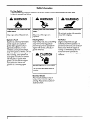
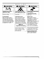
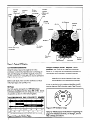
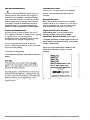
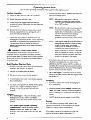
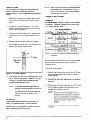
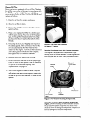
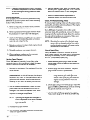
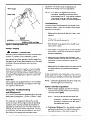
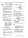
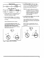
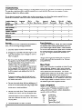
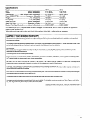
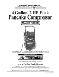
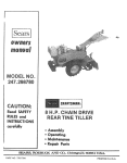
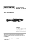
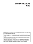
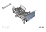
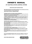
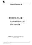
I
OWNE
/
Y
R
S
MAN UAL
MODELS
(17 hP)
(19 hP)
*with Full Pressure Lubrication
operating and maintenance
instructions
Congratulations - You have selected a fine four-cycle,
twin cylinder, air-cooled engine. Kohler designs long
life strength and on-the-job durability into each engine.. . making a Kohler engine dependable.. .dependability
vou can count on. Here are some reasons why:
Parts subject to the most wear and tear (like cylinders, crankshaft, and camshaft) are made from precision
formulated cast iron. Because the cast iron cylinders can be rebored, these engines can last even longer.
Kohler engines are easy to service. All routine service areas (like the dipstick, oil filter, breaker points, air
cleaner, spark plugs, and carburetor) are easily and quickly accessible.
Every Kohler engine is backed by a worldwide network of over 10,000 distributors and dealers. Service
support is just a phone call away. Call I-800-544-2444
(U.S. & Canada) for Sales & Service assistance.
To keep your engine in top operating
condition,
follow the maintenance
procedures
in this manual.
\
Safety Information
For Your Safety!
These precautions should be followed at all times. Failure to follow these precautions could result
in iniurv to vourself and others,
A WARNING
A WARNING
#
xu
v
ib
Explosive Fuel can cause fires and
severe burns.
Rotating Parts can cause severe
injury.
Stop engine before filling fuel tank.
Stay away while engine is in
operation.
Explosive
Fuel!
Gasoline is extremely flammable
and its vapors can explode if
ignited. Store gasoline only in
approved containers, in well
ventilated, unoccupied buildings,
away from sparks or flames. Do not
fill the fuel tank while the engine is
hot or running, since spilled fuel
could ignite if it comes in contact
with hot parts or sparks from
ignition. Do not start the engine
near spilled fuel. Never use
gasoline as a cleaning agent,
Rotating
Parts!
Keep hands, feet, hair, and clothing
away from all moving parts to
prevent injury Never operate the
engine with covers, shrouds, or
guards removed.
A
Electrical
CAUTION
Shock can cause injury.
Do not touch wires while engine is
running.
Electrical
Shock!
Never touch electrical wires or
components while the engine is
running. They can be sources of
electrical shock.
2
ilr WARNING
Hot Parts can cause severe burns.
Do not touch engine while operating
or just after stopping.
Hot Parts!
Engine components can get
extremely hot from operation. To
prevent severe burns, do not touch
these areas while the engine is
running-or immediately after it is
turned off. Never operate the
engine with heat shields or guards
removed.
Safety Information
A WARNING
(Cont.)
A WARNING
ii
WARNING
&P
Accidental Starts can cause
severe injury or death.
Carbon Monoxide can cause
severe nausea, fainting or death.
Explosive Gas can cause fires and
severe acid burns.
Disconnect and ground spark plug
lead before servicing.
Do not operate engine in closed or
confined area.
Charge battery only in a well
ventilated area. Keep sources of
ignition away.
Accidental Starts!
Before servicing the engine or
equipment, always disconnect the
spark plug leads to prevent the
engine from starting accidentally
Ground the leads to prevent sparks
that could cause fires. Make sure
the equipment is in neutral.
Lethal Exhaust Gases!
Engine exhaust gases contain
poisonous carbon monoxide.
Carbon monoxide is odorless,
colorless, and can cause death if
inhaled. Avoid inhaling exhaust
fumes, and never run the engine in
a closed building or confined area.
California
Proposition 65 Warning
Engine exhaust from this product
contains chemicals known to the
State of California to cause
cancer, birth defects, or other
reproductive harm.
Explosive Gas!
Batteries produce explosive
hydrogen gas while being charged.
To prevent a fire or explosion,
charge batteries only in well
ventilated areas. Keep sparks, open
flames, and other sources of
ignition a way from the battery at all
times. Keep batteries out of the
reach of children. Remove all
je welt-y when servicing batteries.
Before disconnecting the negative
(-) ground cable, make sure all
switches are OFF: If ON, a spark
will occur at the ground cable
terminal which could cause an
explosion if hydrogen gas or
gasoline vapors are present.
3
Control
Panel
(Optional)
/
Throttle
Control
, (Optional)
Choke
Control
(Optional)
Ignition
Coil
381
ug
Dark
ug
\
Blower
Housing
Air Cleaner
Breaker
Points
Oil Fill
\
Vluffler.
/
Air Intake
Screen
Starter Solenoid
V3ptional)
cod
Fins
‘ic
0i;Sump
Starter
Figure 1. Typical KT Engine.
Straight 30-weight (Kohler “Magnum”) oil is
preferred. SAE IOW-30
oil is not recommended
above 32°F. Using this oil substantially increases
consumption and combustion chamber deposits.
Oil Recommendations
Using the proper type and weight of oil in the
crankcase is extremely important. So is checking oil
daily and changing oil and filter regularly. Failure to
use the correct oil, or using dirty oil, causes premature
engine wear and failure.
Before each start, make sure the crankcase
with proper type and quantity of oil.
NOTE:
is filled
oil
Using other than service class SG or SH oil or
extending oil change intervals longer than
recommended can cause engine damage.
A logo or symbol on oil containers identifies the API
service class and SAE viscosity grade. See Figure 3.
Oil Type
Use high quality detergent oil of API (American
Petroleum-Institute)
service class SG or SH. Select
the viscosity based on the air temperature at the time
of operation as shown in the following table.
RECOMMENDED
SAE
I
t
GRADES
I
20
I
-20
TEMPERATURE
I
-10
d2
I
0
RANGE EXPECTED
Figure 2. Viscosity
I
do
I
60
I
IO
I
80
I
20
Logo.
100
1
30
BEFORE NEXT OIL CHANGE
Grades Table.
f
Figure 3. Oil Container
I
I
I
"F -20
'"C -30
VISCOSITY
1
40
Refer to “Maintenance Instructions”
beginning on
page 7 for detailed oil check, oil change, and oil
filter change procedures.
Fuel Recommendations
WARNING: Explosive Fuel!
A
Gasoline is extremely flammable and its vapors can
explode if ignited. Store gasoline only in approved
‘containers, in well ventilated, unoccupied buildings,
away from sparks or flames. Do not fill the fuel tank
while the engine is hot or running, since spilled fuel
could ignite if it comes in contact with hot parts or
sparks from ignition. Do not starf the engine near
spilled fuel. Never use gasoline as a cleaning agent.
Gasoline/Alcohol
blends
Gasohol (up to 10% ethyl alcohol, 90% unleaded
gasoline by volume) is approved as a fuel for Kohler
engines. Other gasoline/alcohol
blends are not
approved.
Gasoline/Ether
blends
Methyl Tertiary Butyl Ether (MTBE) and unleaded
gasoline blends (up to a maximum of 15% MTBE by
volume) are approved as a fuel for Kohler engines.
Other gasoline/ether blends are not approved.
General Recommendations
Engine Identification
Purchase gasoline in small quantities and store in
clean, approved containers. A container with a capacity
of 2 gallons or less with a pouring spout is
recommended. Such a container is easier to handle
and helps eliminate spillage during refueling.
When ordering parts, or in any communication
involving an engine, always give the Model,
Specification, and Serial Numbers of the engine.
Do not use gasoline left over from the previous
season, to minimize gum deposits in your fuel system
and to insure easy starting.
Do not add oil to the gasoline.
Do not overfill the fuel tank. Leave room for the fuel to
expand.
Fuel Type
For best results use only clean, fresh, unleaded
gasoline with a pump sticker octane rating of 87 or
higher. In countries using the Research method, it
should be 90 octane minimum.
Unleaded gasoline is recommended as it leaves less
combustion chamber deposits. Leaded gasoline may
be used in areas where unleaded is not available and
exhaust emissions are not regulated. Be aware
however, that the cylinder head will require more
frequent service.
Numbers
The engine identification numbers appear on decal (or
decals) affixed to the engine shrouding. Include letter
suffixes, if there are any.
Record your engine identification numbers on the
identification label below (Figure 4) for future
reference.
‘MODEL NO.
SPEC. NO.
DISPL (CC)
SERIAL NO.
REFER TO OWNER’S MANUAL FOR
SAFETY, MAINTENANCE SPECS
AND ADJUSTMENTS. FOR SALES
AND SERVICE IN US/CANADA CALL:
I-800-544-2444
I
KOHLER CO. KOHLER, WI USA
Figure 4. Engine Identification
I
Label.
_
5
’
Operating Instructions
Also read the operating
instructions
Pre-Start Checklist
Check oil level. Add oil if low. Do not overfill.
Check fuel level. Add fuel if low.
of the equipment this engine powers.
2. Activate the starter switch. Release the switch as
soon as the engine starts.
NOTE:
After starting the engine, it may be
necessary to leave the choke partially
“on” for a few minutes before moving it
to the “off” position.
NOTE:
Do not crank the engine continuously for
more than IO seconds at a time. If the
engine does not start, allow a 60 second
cool down period between starting
attempts. Failure to follow these
guidelines can burn out the starter motor.
NOTE:
If the engine develops sufficient speed to
disengage the starter but does not keep
running (a false start), the engine
rotation must be allowed to come to a
complete stop before attempting to
restart the engine. If the start is engaged
while the flywheel is rotating, the starter
pinion and flywheel ring gear may clash,
resulting in damage to the starter.
Check cooling air intake areas and external
surfaces of engine. Make sure they are clean and
unobstructed.
Check that the air cleaner components and all
shrouds, equipment covers, and guards are in
place and securely fastened.
Check that any clutches or transmissions
are
disengaged or placed in neutral. This is especially
important on equipment with hydrostatic drive.
The shift lever must be exactly in neutral to
prevent resistance which could keep the engine
from starting.
AA
WARNING:
Lethal Exhaust Gases!
Engine exhaust gases contain poisonous carbon
monoxide. Carbon monoxide is odorless, colorless,
and can cause death if inhaled. Avoid inhaling exhaust
fumes, and never run the engine in a closed building
or confined area.
Cold Weather Starting Hints
1 . Be sure to use the proper oil for the temperature
expected. See Figure 2 on page 4.
2. Declutch all possible
external
If the starter does not turn the engine over, shut
off starter immediately. Do not make further
attempts to start the engine until the condition is
corrected. Do not jump start using another battery
(refer to “Battery” below). See your Kohler Engine
Service Dealer for trouble analysis.
loads.
3. Set speed control at part throttle position.
3 . On a Cold Engine - Gradually return the choke
control to the “off” position after the engine starts
and warms up.
I
4. A warm battery has much more starting capacity
that a cold battery.
5. Use fresh winter grade fuel. NOTE: Winter grade
gasoline has a higher volatility to improve
starting. Do not use gasoline left over from
summer.
Starting
1. On a Cold Engine - Place the throttle control
midway between the “slow” and “fast”
positions. Place the choke control into the “on”
position.
On a Warm Engine (Normal Operating
Temperatures) - Place the throttle control
midway between the “slow” and “fast”
positions. Place the choke control into the “off”
position.
6
Stopping
1. If possible, remove the load by disengaging
PTO attachments.
.
all
2. Place the throttle control midway* between the
“stop” and “fast” positions. Allow the engine to
run for a minimum of 15 seconds; then stop the
engine.
*NOTE: Minimum engine speed of 2400 RPM.
Battery
A 12 volt battery is normally used. Refer to the
operating instructions of the equipment this engine
powers for specific battery requirements.
If the battery charge is not sufficient to crank the
engine, recharge the battery (see page 11).
.
Operating
Cooling
Optional spark arrestor mufflers are available from
your Kohler Engine Service Dealer. Check your local
1aw.sand statutes regarding engine spark arrestor
muffler requirements.
NOTE:
Angle of Operation
This engine will operate continuously at angles up to
30’ in any direction. Check oil level to assure
crankcase oil level is at the “F” mark.
Refer to the operating instructions of the equipment
this engine powers. Because of equipment design or
application, there may be more stringent restrictions
regarding the angle of operation.
If debris builds up on the grass screen or
other cooling air intake areas, stop the engine
immediately and clean. Operating the engine
with blocked or dirty air intake and cooling
areas can cause extensive damage due to
overheating.
A
WARNING: Hot Parts!
Engine components can get extremely hot from
operation. To prevent severe burns, do not touch
these areas while the engine is running-or
immediately after it is turned off. Never operate the
engine with heat shields or guards removed.
Engine Speed
NOTE: Do not operate this engine continuously at
angles exceeding 30’ in any direction,
Engine damage could result from insufficient
lubrication.
NOTE:
Do not tamper with the governor setting to
increase the maximum engine speed.
Overspeed is hazardous and will void the
engine warranty.
Maintenance Instructions
A
WARNING: Accidental Starts!
Before servicing the engine or equipment, always disconnect the spark plug leads to prevent the engine from
starting accidentally Ground the leads to prevent sparks that could cause fires. Make sure the equipment is in
neutral.
Maintenance
Schedule
These required maintenance procedures should be performed at the frequency stated in the table. They should
also be included as part of any seasonal tune-up.
I
Frequency
1 Maintenance
As Specified
on pages 8 & 9
l
l
l
Service precleaner element’.
l
l
1
Every 25 Hours
1
l
I
Every 50 Hours
I
l
l
Every 100 Hours
l
I
I
l
l
Annually or
Every 500 Hours
l
l
I
l
I
Change oil.
Change oil filter.
Fill fuel tank.
Check oil level.
Check air cleaner for dirty’, loose, or damaged parts.
Check air intake and cooling areas, clean as necessary’.
l
Daily or Before
Starting Engine
Required
Remove cooling shrouds and clean cooling areas’.
I
I
Service air cleaner element’.
Check spark plug condition and gap.
Have
Have
Have
Have
Have
bendix starter drive serviced?
breaker points checked*.
ignition timing checked*.
valve and tappet clearance checked*.
cylinder heads serviced2f3.
I
1Perform these maintenance procedures more frequently under extremely dusty, dirfy conditions.
2Have a Kohler Engine Service Dealer perform this service.
3250 hburs when leaded gasoline is used.
7
Check Oil Level
NOTE:
The importance of checking and maintaining the
proper oil level in the crankcase cannot be
overemphasized.
Check oil BEFORE EACH USE as
follows:
Make sure the oil level is checked BEFORE
EACH USE and is maintained up to the “F”
mark on the dipstick. This includes engines
equipped with Oil SentryTM.
Change Oil and Oil Filter
1. Make sure the engine is stopped, level, and is
cool so the oil has had time to drain into the
sump.
2. To keep dirt, grass clippings, etc., out of the
engine, clean the area around the oil fill cap or
dipstick before removing it.
3. Remove the dipstick; wipe oil off. Reinsert the
dipstick and push it all the way down into the
tube.
Change Oil
For a new engine, change oil after the first 5 hours
of operation. Thereafter, change oil as shown in the
“Oil Change Intervals” table.
Oil Change Intervals
1
Oil Type
1 Engine Type
1
Interval
Temperature ABOVE 32” F (0” C)
I
With Filter
50 Hours*
SAE 30
Without Filter
25 Hours
4. Remove the dipstick and check the oil level.
With Filter
Multiviscosity
Without
The oil level should be up to, but not over, the “F”
mark on the dipstick. See Figure 5.
Temperature
a%-
25 Hours
25 Hours
BELOW 32” F (0” C)
With Filter
Multiviscosity
Without
*NOTE:
Filter
1
Filter
25 hours for continuous
operation.
50 Hours
25 Hours
and/or heavy duty
“F” Mark
in-
Change the oil while the engine is still warm. The oil
.-......v.
..
..
..
..
..
..
...
:.:.:.:.:.z.:.:.:.:
.
.
.
Operating
:;;;;:;:i:j;:;:
will flow freely and carry away more impurities. Make
:.:+:.:*:.:.:*:.:
'.'.‘.-.*.'.-.*.*.*
.
.
Range..-.*.-.-.-_*.*.-.*
~~TTC~J:
sure the engine is level when filling, checking, or
..I.......
..
..
...
..
..
..
_.
1 ~oia
I
;Li
Figure 5. Oil Level Dipstick.
5. If the level is low, add oil of the proper type, up to
the “F” mark on the dipstick. (Refer to “Oil Type”
on page 4.) Always check the level with the
dipstick before adding more oil.
NOTE:
To prevent extensive engine wear or
damage, always maintain the proper oil
.level in the crankcase. Never operate
the engine with the oil level below the “L”
mark or over the “F” mark on the
dipstick.
Oil SentryTM
Some engines are equipped with an optional Oil
SentryTM oil pressure switch. If the oil pressure
decreases below an acceptable level, the Oil SentryTM
will either shut off the engine or activate a warning
signal, depending on the application.
8
changing
the oil.
Change the oil as follows:
1. Remove the oil drain plug and oil fill cap. Tilt the
engine slightly towards the oil drain to obtain
better drainage.
2. Reinstall the drain plug. Make sure it is tightened
securely.
3. Fill with new oil of the proper type to the “F” mark
on the dipstick. Always check the level on the
dipstick before adding more oil.
NOTE:
To prevent extensive engine wear or
damage, always maintain the proper oil
level in the crankcase. Never operate
the engine with the oil level below the “L”
mark or over the “F” mark on the
dipstick.
4. Reinstall the oil fill cap. Make sure it is tightened
securely.
-.
.
I
Change Oil Filter
Some engines are equipped with an oil filter. Replace
the oil filter every other oil change, in accordance with
the “Oil Change Intervals” table on page 8. Always
use a genuine Kohler oil filter, Part No. 52 050 02, and
replace as follows:
1 . Drain the oil from the engine crankcase.
2. Allow the oil filter to drain.
3 . Remove the old filter and wipe the filter adapter
gasket surface.
4 . Place a new replacement filter in a shallow pan
with the open end up. Pour new oil of the proper
type, in through the threaded center hole. Stop
pouring when the oil reaches the bottom of the
threads.
5. Put a drop of oil on your fingertip and wipe it on
the rubber gasket. Allow a minute or two for the
oil to be absorbed by the filter material then
install it on the engine. Turn the oil filter clockwise
until rubber gasket contacts the filter adapter,
then tighten filter an additional l/2 turn.
6 . Reinstall drain plug. Make sure it is tight.
7. Fill the crankcase with new oil of the proper type
to the ‘IF” mark on the dipstick. Add an additional
l/2 pint of oil for the filter capacity. See
“Specifications” on page 15.
Figure 6. Oil Filter and Optional
Oil SentryTM Switch.
Service Precleaner and Air Cleaner
Element
This engine is equipped with a replaceable, high
density paper air cleaner element. Some engines are
also equipped with an oiled, foam precleaner which
surrounds the paper element. See Figure 7.
Element
Cover Seals
Element
8 . Test run the engine to check for leaks. Stop the
engine, allow a minute for the oil to drain down,
and recheck the level on the dipstick. Make sure
oil level is up to but not over the “F” mark on the
dipstick.
Precleaner
Air Cleaner
Base
Element
Figure 7. Air Cleaner Housing
Components.
Check the air cleaner daily or before starting the
engine. Check for buildup of dirt and debris around
the air cleaner system. Keep this area clean. Also
check for loose or damaged components. Replace all
bent or damaged air cleaner components.
9
NOTE: Operating the engine with loose or damaged
air cleaner components could allow unfiltered
air into the engine causing premature wear
and failure.
Service Precleaner
If so equipped, wash and reoil the precleaner every
25 hours of operation (more often under extremely
dusty or dirty conditions).
1. Remove wing nuts, air cleaner cover, element
cover, seals, and element cover.
2. Remove precleaner from paper element. Wash
the precleaner in warm water with detergent.
- 3. Rinse the precleaner thoroughly until all traces of
detergent are eliminated. Squeeze out excess
water (do not wring). Air dry.
6. Reinstall element cover, seals, air cleaner cover
and wing nuts. Tighten wing nuts l/2 to 1 full turn
after nuts contacts cover. Do not over-tighten.
7. When ai r cleaner element replacement is
necessa .ry always use genuine Kohler parts.
Clean Air Intake/Cooling Areas
To ensure proper cooling, make sure the grass screen,
cooling fins, and other external surfaces of the engine
are kept clean at all times.
Every 50 hours of operation (more often under
extremely dusty, dirty conditions), remove the blower
housing and other cooling shrouds. Clean the cooling
fins and external surfaces as necessary. Make sure
the cooling shrouds are reinstalled.
4. Saturate precleaner in clean, fresh engine oil and
squeeze out excess oil.
NOTE: Operating the engine with a blocked grass
screen, dirty or plugged cooling fins, and/or
cooling shrouds removed, will cause engine
damage due to overheating.
5. Reinstall precleaner over paper element.
Check Spark Plug
6. When precleaner replacement is necessary
always use genuine Kohler parts.
Every 100 hours of operation, remove the spark
plugs, check condition, and reset gaps or replace with
new plugs as necessary. Use a Champion@ type
RV15YC (or equivalent) spark plug.
Service Paper Element
Every 100 hours of operation (more often under
extremely dusty or dirty conditions), check the paper
element. Replace the element as necessary.
1 . Remove the precleaner (if so equipped) from the
paper element.
2. Do not wash the paper element or use
pressurized air, as this will damage the element.
Replace a dirty, bent, or damaged element with a
genuine Kohler element. Handle new elements
carefully; do not use if the sealing surfaces are
bent or damaged.
3 . With air cleaner disassembled, check the base
plate. Make sure it is secured and not bent or
damaged. Also check the element cover, seals,
and breather tube for damage or improper fit.
Replace all damaged components.
NOTE: Operating the engine with damaged or
loose components could allow unfiltered
air into the engine causing premature
wear and failure.
4. Reinstall the paper element.
5. If so equipped, install the precleaner (washed and
oiled) over paper element.
10
1. Before removing spark plugs, clean the area
around base of plugs to keep dirt and debris out
of the engine.
2. Remove plugs and check condition. Replace
plugs if worn or reuse is questionable.
NOTE: Do not clean the spark plug in a machine
using abrasive grit. Some grit could
remain in the spark plug and enter the
engine causing extensive wear and
damage.
3 . Check gaps using a wire feeler gauge. Adjust the
gaps to 0.025 in. (0.65 mm) by carefully bending
the ground electrode. See Figure 8.
4 . Reinstall spark plugs into the cylinder heads.
Torque spark plugs to 1 O-15 ft. lb. (14-20 Nom).
., .
’
adjustment. The main fuel jet is calibrated and
installed at the factory and is not adjustable*.
*NOTE:
KT17 and KT19 engines with fixed jet
carburetors, operating at altitudes above
approximately 6000 ft., may require a special
“high altitude” main jet. See your Kohler
Engine Service Dealer for further information.
Troubleshooting
If engine troubles are experienced that appear to be
fuel system related, check the following areas before
adjusting the carburetor.
l
l
Ground
Electrode
Make sure the fuel tank is filled with clean, fresh
gasoline.
Make sure the fuel tank cap vent is not blocked
and that it is operating properly.
0.025 in. (0.65 mm) Gap
Figure 8. Servicing
Spark Plug.
l
Battery Charging
l
A
WARNING: Explosive Gas!
Batteries produce explosive hydrogen gas while being
charged. To prevent a fire or explosion, charge
batteries only in well ventilated areas. Keep sparks,
open flames, and other sources of ignition a way from
the battery at all times. Keep batteries out of the reach
of children. Remove all jewelry when servicing
batteries.
l
l
Before disconnecting the negative (-) ground cable,
make sure all switches are OFF: If ON, a spark will
occur at the ground cable terminal which could cause
an explosion if hydrogen gas or gasoline vapors are
present.
Fuel Filter
Some engines are equipped with an in-line fuel filter.
Periodically inspect the filter and replace when dirty.
Use a genuine Kohler filter.
Carburetor Troubleshooting
and Adjustments
KTI 7 and KTI 9 engines are equipped with one of two
basic types of carburetors - Kohler or VVa/bro - fixed
main jet or adjustable main jet.
The carburetor is designed to deliver the correct
fuel-to-air mixture to the engine under all operating
conditions. The main fuel and idle fuel needles on
adjustable jet carburetors are set at the factory and
normally do not require further adjustment. On fixed
jet carburetors, the low idle fuel needle is also set at
the factory and normally does not need further
If the fuel tank is equipped
make sure it is open.
with a shutoff valve,
If the engine is equipped with an in-line fuel filter,
make sure it is clean and unobstructed. Replace
the filter if necessary.
Make sure fuel is reaching the carburetor. This
includes checking the fuel lines and fuel pump for
restrictions or faulty components, replace as
necessary.
Make sure the air cleaner element is clean and all
air cleaner element components are fastened
securely.
If, after checking the items listed above, the engine is
hard to start, runs roughly, or stalls at low idle speed, it
may be necessary to adjust or service the carburetor.
NOTE:
Carburetor adjustments should be made only
after the engine has warmed up.
Kohler Carburetor Adjustment
1. With the engine stopped, turn the low idle fuel
and main fuel adjusting needles in (clockwise)
until they bottom lightly.
NOTE:
The tip of the idle fuel and main fuel
adjusting needles are tapered to critical
dimensions. Damage to the needles and
the seats in carburetor body will result if
the needles are forced.
2. Preliminary Settings: Turn the adjusting needles
out (counterclockwise)
from lightly bottomed to
the positions shown in the chart on page 12.
11
Kohler Adjustable
Jet
Low Idle
1
Main Fuel
1
1
1 KT17
1
1 turn
1
2-l/2 turns
1 KT19
1
1 turn
I
2-l/2 turns
Lean
Adjust To
Midpoint
3. Start the engine and run at half throttle for 5 to IO
minutes to warm up. The engine must be warm
before making final settings (steps 4, 5, 6, and 7).
4. Main Fuel Needle Setting: This adjustment is
required for adjustable main jet carburetors only.
If the carburetor is a fixed main jet type, refer to
Walbro adjustment.
Turn the main fuel adjusting needle out
(counterclockwise)
from the preliminary setting
until the engine speed decreases (rich). Note the
position of the needle.
Now turn the adjusting needle in (clockwise). The
engine speed may increase, then it will decrease
as the needle is turned in (lean). Note the position
of the needle.
Figure 9.
7. Recheck the idle speed using a tachometer.
Readjust the speed as necessary.
Walbro Carburetor Adjustment
In general, turning the adjusting needles in (clockwise)
decreases the supply of fuel to the carburetor. This
gives a leaner fuel-to-air mixture. Turning the
adjustment needles out (counterclockwise)
increases
the supply of fuel to the carburetor.
Set the adjusting needle midway between the
rich and lean settings.
Idle Speed
Screw
5. Low Idle Speed Setting: Place the throttle
control into the “idle” or “slow” position. Set the
low idle speed to 1200 RPM* (+ 75 RPM) by
turning the low idle speed adjusting screw in or
out. Check the speed using a tachometer.
*NOTE: The actual low idle speed depends on
the application - refer to equipment
manufacturer’s
recommendations.
The
recommended low idle speed for basic
engines is 1200 RPM. To ensure best
results when setting the low idle fuel
needle, the low idle speed must not
exceed 1500 RPM.
6 . Low Idle Fuel Needle Setting: Place the throttle
into the “idle” or “slow” position.
Turn the low idle fuel adjusting needle out
(counterclockwise)
from the preliminary setting
until the engine speed decreases (rich). Note the
position of the needle.
Now turn the adjusting needle in (clockwise). The
engine speed may increase, then it will decrease
as the needle is turned in (lean). Note the position
of the needle.
Set the adjusting needle midway between the
rich and lean settings.
Figure 10.
NOTE:
The tip of the low idle fuel and main fuel
adjusting needles are tapered to critical
dimensions. Damage to the needles and the
seats in carburetor body will result if the
needles are forced.
1. With the engine stopped, turn the adjusting
needle(s) in (clockwise) until it bottoms light/y.
2. Preliminary Settings: Turn the adjusting
needle(s) out (counterclockwise)
from lightly
bottomed as follows or to the rich side of
adjustment.
Walbro Fixed Jet
,
Low Idle
KT17
1 -l/4 turns
KT19
l-1 /4 turns
Walbro Adjustable
Jet
Low idle
Main Fuel
KT17
1-l /4 turns
i-1/4 turns
KT19
1-I /4 turns
1 turn
3. Start the engine and run at half throttle for five to
ten minutes to warm up. The engine must be
warm before making final settings.
4. Main Fuel Needle Setting: This adjustmenf is
required only for adjustable main jet carburetors.
If the carburetor is a fixed main jet type, disregard
this setting.
Place the throttle into the “fast” position.
Turn the adjusting needle in (clockwise). The
engine speed may increase, then it will decrease
as the needle is turned in (lean). Note the
position of the needle. Back the needle out
approximately l/4 turn. See Figure 11 below for
best main fuel performance.
Lean
Back out
Appx. 118
to 114
turn.
I
5. Low Idle Speed Setting: Place the throttle
control into the “idle” or “slow” position. Set the
low idle speed to 1200 RPM* (k 75 RPM) by
turning the low idle speed adjusting screw in or
out. Check the speed using a tachometer.
*NOTE: The actual low idle speed depends on
the application. Refer to the equipment
manufacturer’s instructions for specific
low idle speed settings. To ensure best
results when setting the low idle fuel
needle, the low idle speed must not
exceed 1500 RPM.
6. Low Idle Fuel Needle Setting:
into the “idle” or “slow” position.
I
“J _[[
Place the throttle
Turn the adjusting needle in (clockwise). The
engine speed may increase, then it will decrease
as the needle is turned in (lean). Note the position
of the needle.
Back the needle out approximately
l/8 to l/4
turn. See Figure 12 below for best low idle fuel
performance.
Lean
Lean
1
\
\
CI
\I
@
Back out
Appx. 118
to 114
turn.
I
I
I
Lean
/
-- v
I
I
e
/+
1
Figure 12. Optimum Low Idle Fuel Setting.
Figure 11. Optimum
Main Fuel Setting.
13
Troubleshooting
When troubles occur, be sure to check the simple causes which, at first, may seem to obvious to be considered.
For example, a starting problem could be caused by an empty fuel tank. Some common causes of engine
troubles are listed in the following table.
Do not attempt to service or replace major engine components, or any items that require special timing or
adjustment procedures. Have your Kohler Engine Service Dealer do this work.
Possible Cause No
Problem
Fuel
Will Not Start
Hard Starting
Improper
Fuel
l
l
Stops Suddenly
Lacks Power
0
l
0
Dirt In
Dirty
Fuel Line Grass Screen
0
0
0
0
0
0
Operates Erratically
Knocks or Pings
0
0
0
0
0
Skips or Misfires
Backfires
0
0
0
0
0
0
Overheats
High Fuel Consumption
Incorrect
Oil Level
Engine
Overloaded
0
0
Dirty Air
Cleaner
0
0
0
0
0
0
0
0
0
0
0
0
0
0
0
0
0
0
0
0
0
Faulty
Spark Plug
0
l
l
l
0
Storage
Parts Ordering
If the engine will be out of service for two months or
more, use the following storage procedure:
The engine Specification, Model, and Serial Numbers
are required when ordering replacement parts from
your Kohler Engine Service Dealer. These numbers
are found on the identification plate which is affixed to
the engine shrouding. Include letter suffixes if there
are any. See “Engine Identification Numbers” on
page 5.
1 . Clean the exterior surfaces of the engine.
2 . Change the oil and filter while the engine is still
warm from operation. See “Change Oil and Oil
Filter” on page 8.
Always insist on genuine Kohler parts. All genuine
3 . The fuel system must be completely emptied, or
the gasoline must be treated with a stabilizer to
prevent deterioration. If you choose to use a
stabilizer, follow the manufacturers
recommendations, and add the correct amount
for the capacity of the fuel system. Fill the fuel
tank with clean, fresh gasoline. Run the engine
for 2-3 minutes to get stabilized fuel into the
carburetor.
To empty the system, drain the fuel tank and
carburetor, or run the engine until the fuel tank
and system are empty.
4. Remove the spark plugs. Add one tablespoon of
engine oil into each spark plug hole. Install plugs,
but do not connect the plug leads. Crank the
engine two or three revolutions.
5 . Remove the spark plugs. Cover one spark plug
hole with your thumb, and turn the engine over
until the piston is at the top of its stroke.
(Pressure against thumb is greatest.) Repeat on
other side. Reinstall the plugs, but do not connect
the plug leads.
6 . Store the engine in a clean, dry place.
14
Kohler parts meet strict standards for fit, reliability,
and performance.
Major Repair
Major repair information is available in Kohler Engine
Service Manuals. However, major repair generally
requires the attention of a trained mechanic and the
use of special tools and equipment. Your Kohler
Engine Service Dealer has the facilities, training, and
genuine Kohler replacement parts necessary to
perform this service. For Sales & Service assistance
call I-800-544-2444 (U.S. & Canada) or contact your
Kohler Engine Dealer or Service Distributor, he’s in
the Yellow Pages under Engines-Gasoline.
Model Designation
Model KT17S for example: KT indicates K-Series twin
cylinder engine, 17 indicates horsepower. Letter
suffixes following the model numbers designates a
specific version, as follows:
Suffix
EP
Q
S
G
Designates
Generator Set
Quiet Model
Electric Start
Tapered Crankshaft
(Generator Application)
’I
Specifications
Model: .............................................................................................
KT17 ............................
Bore: .................................................
inches (millimeters)
inches (millimeters)
Stroke. ................................................
Displacement: .............. cubic inches (cubic centimeters)
Power (@I3600 RPM): ................. horsepower (kilowatts)
Weight* .....................................................
Ibs. (kilograms)
U.S. pints (liters)
Oil Capacity: .........................................
inches (millimeters)
Spark Plug Gap: ...............................
Champion or Equiv.
Spark Plug Type: .............................
Breaker Point Gap (Nominal) ........... inches (millimeters)
.............
.............
.............
.............
.............
.............
.............
.............
.............
KT19
3.12 (79.2) ................... 3.12 (79.2)
2.75 (69.85). ................ 3.06 (78.0)
42.18 (691.3) ............... 46.98 (769.8)
17 (12.7) ...................... 19 (14.2)
128 (58.1) .................... 128 (58.1)
1 .5 (1 .4)’ ......................................
1 .5 (1 .4)l
0.025 (0.65). ................ 0.025 (0.65)
RVI 5YC.. ..................... RVI 5YC
0.020 (0.508)2 .......................
.0.020 (0.508)2
‘An additional pint (0.5 L) required when oil filter is changed. For best results, fill to “F” mark on dipstick as opposed
adding a given quantity of oil.
2After setting point gap, start engine and check timing using a timing light - adjust points as necessary.
to
LIMITED 1 YEAR ENGINE WARRANTY
We warrant to the original consumer that each new engine sold by us will be free from manufacturing defects in materials or workmanship in
normal service for a period of one (1) year from date of purchase, provided it is operated and maintained in accordance with Kohler Co.‘s
instructions and manuals.
Our obligation under this warranty is expressly limited, at our option, to the replacement or repair at Kohler Co., Kohler, Wisconsin 53044, or at a
service facility designated by us, of such part or parts as inspection shall disclose to have been defective.
EXCLUSIONS:
This warranty does not apply to defects caused by casualty or unreasonable use, including faulty repairs by others and failure to provide
reasonable and necessary maintenance.
The following items are not covered by this warranty:
Engine accessories, such as fuel tanks, clutches, transmissions, power drive assemblies, and batteries, unless supplied or installed by Kohler
Co. These are subject to the warranties, if any, of their manufacturers.
WE SHALL NOT BE LIABLE FOR SPECIAL, INDIRECT, INCIDENTAL, OR CONSEQUENTIAL DAMAGES OF ANY KIND, including but not
limited to labor costs or transportation charges in connection with the replacement or repair of defective parts.
ANY IMPLIED OR STATUARY WARRANTIES, INCLUDING WARRANTY OF MERCHANTABILITY OR FITNESS FOR A PARTICULAR
PURPOSE, ARE EXPRESSLY LIMITED TO THE DURATION OF THIS WRITTEN WARRANTY.We make no other express warranty, nor is
anyone authorized to make any in our behalf.
Some states do not allow limitations on how long an implied warranty lasts, or the exclusion or limitation of incidental or consequential damages,
so the above limitation or exclusion may not apply to you.
This warranty gives you specific legal rights, and you may also have other rights which vary from state to state.
TO OBTAIN WARRANTY SERVICE:
Purchaser must bring the engine to an authorized Kohler service facility. For the facility nearest you, consult your Yellow Pages or write Kohler
Co., Attn: Engine Warranty Service Dept., Kohler, Wisconsin, 53044.
ENGINE DIVISION, KOHLER CO., KOHLER, WISCONSIN 53044
ENGINE DIVISION,
KOHLER CO., KOHLER, WISCONSIN
FOR SALES AND SERVICE INFORMATION
IN U.S. AND CANADA, CALL
l-800-544-2444
FORM NO.:
TP-2107-C
ISSUED:
4187
I
REVISED:
12/95
I
MAILED:
LITHO IN U.S.A.
I
53044