1
Installation Guide
Purist™ Effervescent Bath
K-1191-L, K-1191-R, K-1191-LC,
K-1191-RC
M product numbers are for Mexico (i.e. K-12345M)
Los números de productos seguidos de M corresponden a México (e.j.
K-12345M)
Français, page “Français-1”
Español, pagina “Español-1”
1012493-2-A
Important Information
WARNING: When using electrical products, basic precautions should always be followed, including
the following:
DANGER: Risk of electric shock. Connect only to a circuit protected by a Ground-Fault
Circuit-Interrupter (GFCI).
WARNING: Risk of electric shock. A licensed electrician should make all electrical connections.
WARNING: Risk of electrical shock. Disconnect power before servicing.
WARNING: Risk of injury or property damage. Please read all instructions thoroughly before
beginning installation, including the following requirements.
NOTICE: Follow all local plumbing and electrical codes.
Install to permit access for servicing.
A green lead wire is provided within the wiring compartment. To reduce the risk of electrical shock, connect
this wire to the grounding terminal of your electric service or supply panel with copper wire equivalent in
size to the circuit conductor supplying this equipment.
A pressure wire connector is provided on the exterior of the pump or control within this unit to permit
connection of a bonding conductor between this unit and all other exposed metal in the vicinity, as needed to
comply with local requirements.
Grounding is required. The unit should be installed by a qualified service representative, and grounded.
Building materials and wiring should be routed away from the pump body and other heat-producing
components of the unit.
Important Product Information
Product Notices
WARNING: Unauthorized modification may cause unsafe operation and poor performance of the
effervescent bath. Do not relocate the pump, or make other modifications to the overflowing bath
system, as this could adversely affect the performance and safe operation. Kohler Co. shall not be liable
under its warranty or otherwise for personal injury or damage caused by any such unauthorized
modification.
Product Inspection
Carefully unpack the product, and inspect the unit for damage. Return the unit to the carton during
construction to prevent damage.
NOTICE: Make sure the union connections to the pump and in-line heater are securely tightened. Do
not overtighten.
Factory-Assembled Features
Factory installed components include pump, in-line heater, submerged chromatherapy lights, control and
switch. The pump and piping are factory-assembled.
Connections and Service Access
NOTICE: Provide unrestricted service access to the pump. Provide unrestricted service access to the
pump, in-line heater, and control box. You must construct an access panel to provide sufficient clearance
for servicing the pump, in-line heater, and control box. The access panel must be located immediately next
to the pump and in-line heater. Study the roughing-in information.
1012493-2-A
2
Kohler Co.
Important Product Information (cont.)
Electrical Requirements
The installation must have a Class A Ground-Fault Circuit-Interrupter (GFCI). The GFCI protects against
line-to-ground shock hazard. Use a 240V, 15A, 60 Hz dedicated service.
An equipment grounding terminal is provided in the field wiring compartment. To reduce the risk of
electrical shock, this terminal must be connected to the grounding means provided in the electrical supply
panel with a conductor equivalent in size to the circuit conductors supplying this equipment.
Install this unit in accordance with the Canadian Electric code, Part I.
Table of Contents
Important Information . . . . . . . . . . . . . . . . . . . . . . . . . . . . . . . . . . . . . . . . . . . . . . . . . . . . . . . . . . . . . . 2
Important Product Information . . . . . . . . . . . . . . . . . . . . . . . . . . . . . . . . . . . . . . . . . . . . . . . . . . . . . . . 2
Product Notices . . . . . . . . . . . . . . . . . . . . . . . . . . . . . . . . . . . . . . . . . . . . . . . . . . . . . . . . . . . . . . . . 2
Product Inspection . . . . . . . . . . . . . . . . . . . . . . . . . . . . . . . . . . . . . . . . . . . . . . . . . . . . . . . . . . . . . . 2
Factory-Assembled Features . . . . . . . . . . . . . . . . . . . . . . . . . . . . . . . . . . . . . . . . . . . . . . . . . . . . . . 2
Connections and Service Access . . . . . . . . . . . . . . . . . . . . . . . . . . . . . . . . . . . . . . . . . . . . . . . . . . . 2
Electrical Requirements . . . . . . . . . . . . . . . . . . . . . . . . . . . . . . . . . . . . . . . . . . . . . . . . . . . . . . . . . . 3
Thank You For Choosing Kohler Company . . . . . . . . . . . . . . . . . . . . . . . . . . . . . . . . . . . . . . . . . . . . . . 4
Recommended Tools and Materials . . . . . . . . . . . . . . . . . . . . . . . . . . . . . . . . . . . . . . . . . . . . . . . . . . . 4
Introduction . . . . . . . . . . . . . . . . . . . . . . . . . . . . . . . . . . . . . . . . . . . . . . . . . . . . . . . . . . . . . . . . . . . . . 4
Before You Begin . . . . . . . . . . . . . . . . . . . . . . . . . . . . . . . . . . . . . . . . . . . . . . . . . . . . . . . . . . . . . . . . . 4
List of New Terms . . . . . . . . . . . . . . . . . . . . . . . . . . . . . . . . . . . . . . . . . . . . . . . . . . . . . . . . . . . . . . . . 5
Roughing In Information . . . . . . . . . . . . . . . . . . . . . . . . . . . . . . . . . . . . . . . . . . . . . . . . . . . . . . . . . . . . 7
Construct the Stud Framing . . . . . . . . . . . . . . . . . . . . . . . . . . . . . . . . . . . . . . . . . . . . . . . . . . . . . . . . . 7
Install the Rough Plumbing . . . . . . . . . . . . . . . . . . . . . . . . . . . . . . . . . . . . . . . . . . . . . . . . . . . . . . . . . . 7
Prepare the Unit . . . . . . . . . . . . . . . . . . . . . . . . . . . . . . . . . . . . . . . . . . . . . . . . . . . . . . . . . . . . . . . . . 7
Position the Unit . . . . . . . . . . . . . . . . . . . . . . . . . . . . . . . . . . . . . . . . . . . . . . . . . . . . . . . . . . . . . . . . . 8
Install the Plumbing . . . . . . . . . . . . . . . . . . . . . . . . . . . . . . . . . . . . . . . . . . . . . . . . . . . . . . . . . . . . . . . 8
Make the Electrical Connections . . . . . . . . . . . . . . . . . . . . . . . . . . . . . . . . . . . . . . . . . . . . . . . . . . . . . . 9
Test Run the Bath . . . . . . . . . . . . . . . . . . . . . . . . . . . . . . . . . . . . . . . . . . . . . . . . . . . . . . . . . . . . . . . . 9
Check the Connections and Fill the Unit . . . . . . . . . . . . . . . . . . . . . . . . . . . . . . . . . . . . . . . . . . . . . . 9
Test the Control Switch . . . . . . . . . . . . . . . . . . . . . . . . . . . . . . . . . . . . . . . . . . . . . . . . . . . . . . . . . . 9
Complete the Finished Wall or Deck . . . . . . . . . . . . . . . . . . . . . . . . . . . . . . . . . . . . . . . . . . . . . . . . . . 11
Install the Faucet Trim . . . . . . . . . . . . . . . . . . . . . . . . . . . . . . . . . . . . . . . . . . . . . . . . . . . . . . . . . . . . 11
Clean-Up After Installation . . . . . . . . . . . . . . . . . . . . . . . . . . . . . . . . . . . . . . . . . . . . . . . . . . . . . . . . . 11
Using Your Bath . . . . . . . . . . . . . . . . . . . . . . . . . . . . . . . . . . . . . . . . . . . . . . . . . . . . . . . . . . . . . . . . . 12
Fill the Bath . . . . . . . . . . . . . . . . . . . . . . . . . . . . . . . . . . . . . . . . . . . . . . . . . . . . . . . . . . . . . . . . . . 12
Operating Sequence . . . . . . . . . . . . . . . . . . . . . . . . . . . . . . . . . . . . . . . . . . . . . . . . . . . . . . . . . . . 12
Chromatherapy Light Operation . . . . . . . . . . . . . . . . . . . . . . . . . . . . . . . . . . . . . . . . . . . . . . . . . . . . . 13
Kohler Co.
3
1012493-2-A
Thank You For Choosing Kohler Company
We appreciate your commitment to Kohler quality. Please take a few minutes to review this manual before
you start installation. If you encounter any installation or performance problems, please don’t hesitate to
contact us. Our phone numbers and website are listed on the back cover. Thanks again for choosing Kohler
Company.
Recommended Tools and Materials
Pipe
Wrench
Adjustable
Wrench
Assorted
Screwdrivers
Strap
Wrench
Plumbers
Putty
Hacksaw or
Tube Cutter
Thread
Sealant
Solder
Propane
Torch
Introduction
Please read these instructions carefully to familiarize yourself with the required tools, materials, and
installation sequences. Follow the sections that pertain to your particular installation. This will help you
avoid costly mistakes. In addition to proper installation, read all operating and safety instructions.
All information in this manual is based upon the latest product information available at the time of
publication. At Kohler, we constantly strive to improve the quality of our products; we therefore reserve the
right to make changes in product characteristics, packaging, or availability at any time without notice.
Before You Begin
This product is designed for drop-in island installation. Undermount and alcove installations are also
possible.
You must install the bath onto an adequately supported, level subfloor.
Provide properly dimensioned framing.
Choose a fill spout which will provide adequate reach and a minimum 2” (5.1cm) air gap above the
bathing well rim of the unit. You may need to build up the deck material to obtain adequate air space
because the outer rim may be lower than the bathing well rim depending on the specific area of the bath.
Follow local plumbing codes.
The unit must be filled with water through the bathing well, not the overflow channel.
If you plan to install a deck-mounted, hand-held shower, the diverter vacuum breaker must maintain a
minimum 1” (2.5cm) air gap above the outer rim.
When using the K-922 or K-923 Laminar Bath Spout with drip tray K-924, the distance from the finished
wall to the outside wall of overflow channel should not exceed 2” (5.1cm).
1012493-2-A
4
Kohler Co.
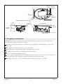
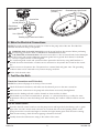
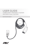
System Controll ( On/Off )
Bathing
Well Rim
Bathing Well
Effervescence Port
Overflow Drain
Overflow
Channel
Chromatherapy
Lights
Chromatherapy Light Control
Pump Motor
1. List of New Terms
Bathing well-The deep portion on the bath used by the bather.
Bathing well rim-The high rim between the bathing well and the overflow channel. Water will cascade
over the bathing well rim and into the overflow channel when entering the bath.
Cavitation-When air is drawn into the pump instead of water to a point where it impairs or stops the
pump’s ability to circulate water.
Chromatherapy lights-Lights provided in the basin of the bath to enhance your bathing experience.
Outer rim-The rim along the outside of the bath.
Overflow channel-The overflow water collection channel at the drain end.
Plastic suction cover-The plastic guard attached over the water intake port located in the bathing well.
The suction cover must always be installed during product use to ensure user safety.
Kohler Co.
5
1012493-2-A
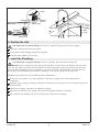
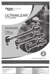
12-3/16” 3-15/16”
(31cm) (10cm)
46”
(116.8cm)
23”
(58.4cm)
PUMP/CONTROL ACCESS
1-3/16”
(3cm)
25-3/16”
(64cm)
1-3/8”
(3.5cm)
72” (182.9cm)
6-3/8”
(16.2cm)
24”
(61cm)
6” (15.2cm)
1-1/2” O.D.
7/16” (1.1cm)
132
2. Roughing In Information
NOTICE: Unless otherwise specified, floor support under the bath must provide for a minimum of 80
lbs./square foot (390 Kg./square meter) loading.
Consult local and national codes for a minimum air gap requirements when installing a spout on the
faucet deck.
Unit requires two (minimum) 40 gal. (151L) water heaters.
Fixture conforms to ANSI Standard Z124.1. All dimensions are nominal.
No change in measurements if connected with drain illustrated.
Cut-Out = See template supplied with unit.
An access panel is required. The recommended dimensions for this access panel are 40” (101.6cm) W x 15”
(38.1cm) H. Refer to the roughing-in diagram for suggested access panel location.
Make sure the flooring is in good condition, and offers adequate support for your bath.
1012493-2-A
6
Kohler Co.
9-1/2"
(24.1cm)
7"
(17.8cm)
Deck
6-1/2"
(16.5cm)
3. Construct the Stud Framing
NOTICE: Provide unrestricted service access to the pump, in-line heater and control box. You must
construct an access panel to provide sufficient clearance for servicing the pump, in-line heater, and control
box.
Construct stud framing designed for your particular installation.
Frame the floor, or construct a frame for a raised installation in accordance with the roughing-in
information. When constructing the framing, allow for the thickness of sub and finished deck materials.
Framing should be of 2x4 construction.
Do not support the unit by the rim.
When planning the stud framing, take into account the required 2″ (5.1cm) air gap between the end of the
fill spout and the top of the bathing well rim. Take into account the thickness of your planned finished
deck material, and construct the framing and deck material with this minimum air gap in mind.
4. Install the Rough Plumbing
IMPORTANT! Choose a fill spout which will provide a minimum 2″ (5.1cm) air gap above the basin rim
of the unit. In addition, if you plan to install a deck-mounted, hand-held shower, the diverter vacuum
breaker must maintain a minimum 1″ (2.5cm) air gap above the outer rim of the unit.
NOTE: The listed Kohler spouts are designed to work with this bath at the listed location. There may be
additional spouts that are not listed.
At the locations marked 9–1/2” (24.1cm), the Stillness™ Floor Mount Bath Filler Spout (K-8358), and the
Stillness™ Laminar Ceiling/Wall Mount Faucet (K-923) are appropriate choices.
At the locations marked 7” (17.8cm) and 6–1/2” (16.5cm) the previously listed models apply along with
the Stillness™ Deck-Mount High Flow Bath Faucet (K-954–4), the Finial Deck-Mount High Flow Bath
Faucet (K-T314), the Alterna™ Deck-Mount High Flow Bath Faucet, and the Kallista Barbara Barry
(P22603).
Position the plumbing. Position the fill spout supply so the spout will reach beyond both the outer rim
and the bathing well rim. Water from the fill spout must be directed into the bathing well to fill the
unit. The fill spout must reach beyond the inner edge of the overflow channel.
Cap the supplies, and check for leaks.
5. Prepare the Unit
Carefully lift the unit out of the carton.
Install the drain according to the drain manufacturer’s instructions. Do not connect the trap at this time.
Position a clean drop cloth or similar material in the bottom of the bath. Be careful not to scratch the
surface of the product.
Kohler Co.
7
1012493-2-A
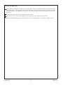
Pump
Drainage
Banding
Straps
Suction Line
Outer Rim
Drainage
2" MIN.
(5.1cm)
Inner Rim
Suction Line
Bathing Well
6. Position the Unit
CAUTION: Risk of product damage. Do not lift or support the unit by the pump or piping.
With help, carefully lift the unit into place.
Cut and discard the banding straps from the pump.
Insert the drain tailpiece into the trap.
7. Install the Plumbing
CAUTION: Risk of property damage. Ensure a watertight seal on the drain connections.
IMPORTANT! Choose a fill spout which will provide adequate air space above the bathing well rim of the
unit. You may need to build up the deck material to obtain adequate air space because the outer rim may
be lower than the bathing well rim. In addition, if you plan to install a deck-mounted, hand-held shower,
the diverter vacuum breaker must maintain a minimum 1″ (2.5cm) air gap above the outer rim.
NOTE: An access panel must be installed for future maintenance.
If you have not yet done so, connect the drain to the trap according to the drain manufacturer’s
instructions.
Install the faucet valving according to the faucet manufacturer’s instructions. Do not install the faucet trim
until instructed.
Make sure all supply connections are tightened securely.
Open the hot and cold water supplies, and check the supply connections for leakage.
Run water into the bathing well, and check the drain connections for leakage.
1012493-2-A
8
Kohler Co.
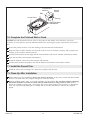
System Control
("On/Off")
Junction Box
Line 1 (Black)
Black
Ground (Green)
Green
Electrician to
provide suitable
strain relief
Line 2 (Black)
Chromatherapy Light Control
Black
Bonding Lugs Follow Local Codes
8. Make the Electrical Connections
NOTE: The product model number is printed on a label on the pump side of the unit. This label also
identifies the electrical rating of the product.
WARNING: Risk of electrical shock.Make sure the power has been disconnected before performing
the following procedures. Refer to IMPORTANT INFORMATION section.
CAUTION: Risk of electrical shock. All services must have a Class A Ground-Fault Circuit-Interrupter
(GFCI) which will provide additional protection against line-to-ground shock hazard. A dedicated
service is required for the overflowing bath.
The overflowing bath control and system have been prewired at the factory using 220V hardwire. A
licensed electrician should make a routine service connection to the junction box located on the control
box.
Connect service to the junction box. The junction box contains black and green wires. The grounding
conductor must not be connected to any current-carrying conductor.
Follow local electrical codes.
9. Test Run the Bath
Check the Connections and Fill the Unit
NOTE: The system will purge air at start-up. This is normal.
Check all electrical connections, and make sure the electrical power to the unit is turned on.
Make sure union connections to the pump and in-line heater are securely handtightened.
Make sure the bathing well and overflow channel are clean and free of debris.
Fill the bath as you would a normal bath, 4” (10.2cm) – 6” (15.2cm) from the top, to allow for water
displacement when you enter the bathing well. Water entering the overflow channel will flow into the
drain.
Test the Control Switch
Press the ″On/Off″ control switch to start the pump/motor and begin the hydro-therapy cycle. A green
light in the ″On/Off″ control switch will turn on to indicate the start of the operating mode. As the
pump/motor turns on and water begins to circulate, the light remain green while the unit is running.
With the unit running, check all harness (piping) connections for leaks.
Visually observe the effervescence rising to the surface of the water.
Kohler Co.
9
1012493-2-A
Test Run the Bath (cont.)
Verify that the chromatherapy lights are operating. Upon start-up the lights should be changing through
the color sequence. Press the light control switch (located directly across the bath from the power switch).
The lights should stop sequencing and stay one color. Press the light control switch again and lights will
deactivate.
Check the harness connections for leakage one more time.
Press the ″On/Off″ control switch again to turn off the unit. The switch will also turn off.
NOTE: For additional information on operation of your overflowing bath, see “Using Your Bath” section.
1012493-2-A
10
Kohler Co.
Finished Deck
Material
Bath
Access Panel
Silicone
Sealant
Framing
Water–Resistant
Wall Material
10. Complete the Finished Wall or Deck
NOTICE: Provide unrestricted service access to the pump, in-line heater, and control box. You must
construct an access panel to provide sufficient clearance for servicing the pump, in-line heater, and control
box.
Protect the product surface. Cover the framing with water-resistant wall material.
Keep the entire overflow channel area exposed to allow access to the drain overflow, and to permit easy
cleaning of the overflow channel surfaces.
Seal the joints between the rim edge and the water-resistant wall or deck material with silicone sealant.
Tape and mud the water-resistant wall material.
Install the finished wall to the water-resistant wall material.
Seal the joints between the product rim and the finished wall material with silicone sealant.
11. Install the Faucet Trim
Install the faucet trim according to the instructions packed with the trim.
12. Clean-Up After Installation
When cleaning up after installation, do not use abrasive cleansers, as they may scratch and dull the bath
surface. Use warm water and a liquid detergent to clean the surface.
Remove stubborn stains, paint, or tar with turpentine or paint thinner. Do not allow cleaners containing
petroleum distillates to remain in contact with any bath surfaces for long periods of time. Remove
plaster by carefully scraping with a wood edge. Do not use metal scrapers, wire brushes, or other metal
tools. Use a powder-type detergent on a damp cloth to provide mild abrasive action to any residual
plaster.
Kohler Co.
11
1012493-2-A
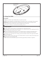
Chromatherapy
Lights
13. Using Your Bath
Fill the Bath
NOTE: Please read these steps carefully before you operate your bath.
NOTE: The water temperature in the bath should not exceed 104° F (40° C) or the heater will not operate.
IMPORTANT! Like any other bath, prevent flooding the area around the unit by entering the filled
bathing well slowly. This will allow the system to properly drain excess water.
Fill the unit 4” (10.2cm) to 6” (15.2cm) from the bathing well rim.
Operating Sequence
Press the ″On/Off″ control switch to start the pump/motor and begin operation.
A green light in the ″On/Off″ control switch will turn on to indicate the start of the operating mode. The
light will remain green while the unit is running.
Verify that the indicator light for the heater is on when the unit is in operation. This indicator light is
located on the underside of the heater box, and is near the subfloor at the pump end of the unit.
If the light is not on when the unit is running, press the reset button located to the right of the indicator
light on the heater box.
Press the “On/Off” control switch again to turn off the bath. The “On/Off” control switch will turn off to
indicate the end of the operating mode.
NOTE: A built-in timer automatically stops the bath after approximately 20 minutes of operation.
1012493-2-A
12
Kohler Co.
14. Chromatherapy Light Operation
The submerged chromatherapy lights automatically turn on in the stationary setting when you start the
bath.
Press the “Lights” control switch (located on the opposite side of the pump control) once and the
submerged chromatherapy lights will slowly cycle through the color spectrum (sweep mode).
The light control switch pulses blue for five seconds at the start of the sweep mode. Press the “Lights”
control switch again to lock the chromatherapy lights in a particular color.
The light control switch is a constant blue in this mode. Press the “Lights” control switch a third time to
turn off the submerged chromatherapy lights.
When restarting the pump the submerged chromatherapy lights will turn back on.
The chromatherapy lights may be turned on when the pump is off. Turning on the pump when the lights
are operating will not affect the lights.
Kohler Co.
13
1012493-2-A
1012493-2-A
Kohler Co.
Kohler Co.
1012493-2-A
USA: 1-800-4-KOHLER
México: 001-877-680-1310
Canada: 1-800-964-5590
kohler.com
©2002 Kohler Co.
1012493-2-A