1
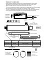
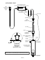
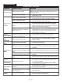
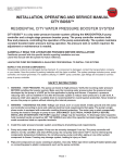
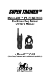
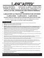
INSTALLATION, OPERATING AND SERVICE MANUAL FOR LANCASTER ULTRAVIOLET DISINFECTION SYSTEMS 7-LWT-UV009 7-LWT-UV016 7-LWT-UV030 PLEASE CAREFULLY READ INSTRUCTIONS BEFORE INSTALLING SYSTEM FOLLOW ALL STATE AND LOCAL CODES AND REGULATIONS FOR PLUMBING AND ELECTRICAL. Safety Instructions: INSTALLATION BY A CERTIFIED PLUMBER IS RECOMMENDED. WARNING - to guard against injury, basic safety precautions should be observed, including the following: 1. READ AND FOLLOW ALL SAFETY INSTRUCTIONS. 2. CAUTION - Always disconnect power before servicing. 3. DANGER - Warning: the UV light given off by this unit can cause serious burns to unprotected eyes and skin. Never look directly at an illuminated UV lamp. When performing any work on the UV disinfection system always unplug the unit first. Never operate the UV system while the UV lamp is outside of the UV chamber. 4. DANGER - To avoid possible electric shock, special care should be taken since water is present near electrical equipment. Unless a situation is encountered that is explicitly addressed by the provided maintenance and troubleshooting sections, do not attempt repairs yourself, refer to a certified plumber/technician. 5. Carefully examine the disinfection system after installation. It should not be plugged in if there is water on parts not intended to be wet such as the ballast or lamp connector. 6. Do not operate the disinfection system if it has a damaged cord or plug, if it is malfunctioning or if it has been dropped or damaged in any manner. 7. Always disconnect water flow and unplug the disinfection system before performing any cleaning or maintenance activities. Never yank the cord to remove from an outlet; grasp the wall plug and pull to disconnect. 8. Do not use this disinfection system for other than intended use (potable water application).The use of attachments not recommended or sold by the manufacturer/distributor may cause an unsafe condition. 9. Intended for indoor use only. Do not install this disinfection system where it will be exposed to the weather or to temperatures below freezing. Do not store this disinfection system where it will be exposed to temperatures below freezing unless all water has been drained from it and the water supply has been disconnected. 10. Read and observe all the important notices and warnings on the water disinfection system. 11. If an extension cord is necessary, a cord with a proper rating should be used. A cord rated for less Amperes or Watts than the disinfection system rating may overheat. Care should be taken to arrange the cord so that it will not be tripped over or pulled. 12. A dedicated circuit breaker must not exceed the electronic ballast power cord current rating (10A for 125V, 18AWG x 3C, SVT or SJT cord type). 13. To avoid creating an electric shock hazard, never attempt to operate the disinfection system unless it has first been properly grounded. 14. To prevent an electric shock, do not plug the disinfection system into any socket that has not been equipped with a Ground Fault Circuit Interrupter (GFCI). 15. SAVE THESE INSTRUCTIONS. Note: The UV lamp inside the disinfection system is rated at an effective life of approximately 9000 hours. To ensure continuous protection, replace the UV lamp annually. PAGE 1 H F-XC A N GE ! W O N y bu to lic k w 7-UVC Electronic Ballast Qty (2): 21S-UV Electronic Ballast Mounting Screw 2'-8" Lamp Cordset with Lamp Connector attached Qty (2): 21A-UV Electronic Ballast Mounting Anchor Ground Screw attached 15-UV Bushing 14-UV Aluminum Gland Nut Electronic Ballast 5 ft. Power Cordset CAUTION: HAND TIGHTEN ONLY! 16-UV U-Clip 17-UV Ground Nut CAUTION: keep quartz sleeve free of finger prints and dirt! OR-212 O-Ring 18-UV Lamp Compression Spring A Four pins CAUTION: handle lamp by the ceramic end caps; keep lamp quartz free of finger prints and dirt! Model SS UV Chamber Domed Quartz Sleeve (length) 7-LWT-UV009 100-UV 7-Q6 (13-1/8") 7-LWT-UV016 200-UV 7-Q10 (21-3/8") 7-LWT-UV030 300-UV 7-Q20 (34-3/4") 19-UV 3 ft. Ground Wire UV Lamp (A) 7-L6 (11-13/16") 7-L10 (20-1/16") 7-L20 (33-3/16") OR-212 O-Ring Qty (4): 20S-UV Mounting Bracket Screw Qty (2): 20-UV UV Chamber Mounting Bracket Qty (4): 20A-UV Mounting Bracket Anchor PAGE 2 (spare) .d o m Please read this manual thoroughly for a detailed explanation of the system. The following is a description of the components that make up the system. Ensure that the following components accompany the system . To ensure system performance, all replacement components should be purchased from an authorized dealer or directly from Lancaster Water Treatment. The use of components purchased from other sources will void the warranty and could cause the system to operate at a lower performance than intended. .c o c u-tr a c k H F-XC A N GE C m .c o .d o PRODUCT OVERVIEW: w w w PD w w C lic k to bu y N O W ! PD c u-tr a c k H F-XC A N GE H F-XC A N GE W O N y bu to lic k A C B D OUTLET F E INLET MODEL A B C D E F (DIA.) INLET/OUTLET 7-LWT-UV009 17-3/8 13-3/8 1-3/8 13-9/16 5 3-1/2 1.0 MNPT 7-LWT-UV016 25-5/8 21-11/16 1-3/8 21-13/16 5 3-1/2 1.0 MNPT 7-LWT-UV030 39-3/4 35-1/16 2-1/8 35-9/16 5-1/4 3-1/2 1.5 MNPT GENERAL NOTES FOR ESTIMATING ONLY. ALL DIMENSIONS ARE IN INCHES. PART NUMBER 7-UVC ELECTRONIC BALLAST/CONTROLLER 3 18 3 16 8 8 16 2 14 1 5 PAGE 3 .d o m w .c o c u-tr a c k C m .c o .d o DIMENSIONS: w w w w w C lic k to bu y N O W ! PD ! PD c u-tr a c k H F-XC A N GE H F-XC A N GE W O N y bu lic k to (1) FLOW RATE ELECTRICAL FLUENCE (UV DOSE) MODEL 7-LWT-UV009 MODEL 7-LWT-UV016 MODEL 7-LWT-UV030 US PUBLIC HEALTH 16mJ/cm 2 17 GPM 35 GPM 55 GPM INDUSTRY STANDARD 30mJ/cm 2 9 GPM 16 GPM 30 GPM NSF/EPA 40mJ/cm 2 7 GPM 14 GPM 22 GPM VOLTAGE (2) 110V to 240V AC 50/60Hz POWER 34 W 50 W 90 W LAMP WATTS 29 W 45 W 80 W 1.0" MNPT 1.0" MNPT 1.5" MNPT CONSUMPTION INLET/OUTLET PORT SIZE MAXIMUM OPERATING PRESSURE 125 PSI PRESSURE DROP at 30mJ/cm 2 RATED FLOW LESS THAN 1 PSI AMBIENT AIR & WATER TEMPERATURE LAMP TYPE 36 to 104°F LOW PRESSURE HIGH OUTPUT (LPHO) CHAMBER MATERIAL 304 SS LAMP-ON INDICATOR STEADY "WORK" GREEN LED LAMP LIFE REMAINING (DAYS) VISUAL COUNT DOWN DISPLAY (365 - 0); MANUAL RESET FUNCTION LAMP REPLACEMENT REMINDER VISUAL DISPLAY (A3), "FAULT" RED LED FLASHES and AUDIBLE ALARM SOUNDS INTERMITTENTLY (1 SEC. BEEP EVERY 5 SEC.) LAMP REPLACEMENT REMINDER DELAY SILENCES AUDIBLE ALARM FOR 7 DAYS, REPEATABLE UP TO 4 TIMES (28 DAYS MAXIMUM) LAMP FAILURE INDICATOR LAMP LIFE REMAINING (DAYS) CONTINUES TO BE DISPLAYED BUT STOPS COUNTING DOWN, "FAULT" RED LED FLASHES and AUDIBLE ALARM SOUNDS INTERMITTENTLY (1 SEC. BEEP EVERY 1 SEC.) BALLAST TOTAL RUNNING DAYS VISUAL INCREMENTAL DISPLAY (0 - 9999); CANNOT BE RESET BALLAST FAILURE INDICATOR BLANK DISPLAY (1) At flow rates stated, the corresponding fluence (UV dose) levels are theoretically met or exceeded at 95% UVT and EOL (end of lamp life; 1 year). R , developed by Bolton Photosciences Inc., is based on calculations of fluence rates (irradiances) using the multiple point source summation approximation with full accomodation of reflection and refraction occurring at the air/quartz/water interface and is the only mathematical fluence rate model that has been experimentally verified. Contact LANCASTER WATER TREATMENT for references. (2) Models are supplied with a 5 FT. power cordset for 120V AC 60 Hz (NEMA 5-15P plug to IEC 60320/C13 connector). PAGE 4 .d o m w .c o c u-tr a c k C m SPECIFICATIONS: .c o .d o w w w w w C lic k to bu y N O W ! PD ! PD c u-tr a c k H F-XC A N GE H F-XC A N GE ! PD ! W O N y lic k to bu c u-tr a c k w .d o m C m Water quality is extremely important for the optimum performance of your UV system. The following levels are .c recommended for installation: o .d o w w w w w C lic k to bu y N O W Water Chemistry: c u-tr a c k • Iron:< 0.3 ppm (0.3 mg/L) • Hardness*:< 7 gpg (120 mg/L) • Turbidity: < 1 NTU • Manganese: < 0.05 ppm (0.05 mg/L) • Tannins: <0.1ppm (0.1 mg/L) • UV Transmittance: > 75% (call factory for recommendations on applications where UVT <75%) *Where total hardness is less than 7 gpg, the UV unit should operate efficiently provided the quartz sleeve is cleaned periodically. If total hardness exceeds 7 gpg, the water should be softened. If your water chemistry contains levels in excess of those mentioned above, proper pre-treatment is recommended to correct these water problems prior to the installation of your UV disinfection system. These water quality parameters can be tested by your local dealer, or by most private analytical laboratories. Proper pre-treatment is essential for the UV disinfection system to operate as intended. Installing your UV Disinfection System: • CAUTION, electronic ballast must be connected to a grounded receptacle. A ground fault protected circuit (GFCI) is recommended. • The disinfection system is designed to be mounted either horizontally or vertically at the point-of-use or point-of-entry depending on the specific flow rate of the unit. NOTE: The ideal installation is vertical with the lamp connector on top. This is to prevent water damage from occurring on the lamp connector and lamp pins. Leave space at least equal to the overall length of the disinfection system to allow clearance for the removal and replacement of the lamp and/or quartz sleeve. • The electronic ballast should be mounted either above or beside the stainless steel UV reactor chamber. Never mount ballast vertically with AC connector at top of ballast to prevent moisture from running down cordage and causing a potential fire hazard. Drip loops in all cordage connected to ballast is highly recommended. • The complete water system, including any pressure or hot water tanks, must be sterilized before start up by flushing with chlorine (household bleach) to destroy any residual contamination (see page 7). • The disinfection system is intended for indoor use only. Do not install disinfection system where it may be exposed to the weather. Protect system from freezing temperature. • Refer to specifications page for ambient conditions and maximum operating pressure. • Install the disinfection system on cold water line only. • If treating the entire house, install the disinfection system before any branch lines. • A 5 micron sediment filter must precede the disinfection system. Ideally, the disinfection system should be the last treatment the water receives before it reaches the faucet. PAGE 5 .c o PD H F-XC A N GE H F-XC A N GE W O N y bu to lic k w 1. The above picture shows the installation of a typical disinfection system and the related components that may be used for the installation. The use of a by-pass assembly is recommended in case the system requires “off-line” maintenance. If this is the case, it must be noted that the system will require supplementary disinfection of the distribution system if any water is used during this by-pass condition. In addition, during by-pass, the water will NOT be disinfected. Please refer to the complete disinfection procedure as outlined on page 7 of this document. If the water is to be consumed while the system is off-line, the water must be boiled for twenty minutes prior to consumption. 2. Select a suitable location for the disinfection system and its related components. As it is recommended to install a ground fault protected circuit (GFCI), make sure that this is taken into consideration prior to any installation. The system can either be installed vertically( inlet port at the bottom), or horizontally, however the vertical installation is the most preferred method. When selecting a mounting location, you must also leave enough space to allow for the removal of the UV lamp and/or quartz sleeve (minimum clearance equal to disinfection system overall length; refer to dimensions page). 3. Install the quartz sleeve as outlined on page 8. 4. Mount the system to the wall using the supplied clamps. Various connection methods can be used to connect the water source to the system, however union type connectors are recommended. The use of a flow restrictor device is strongly recommended when installing your system in order to maintain the manufacturer’s rated flow rate. The flow restrictor should be installed on the outlet port and is designed to be installed in one direction only. Ensure that the flow of the water matches the flow direction as indicated on the flow restrictor. DO NOT SOLDER CONNECTIONS WHILE ATTACHED TO THE SYSTEM AS THIS COULD DAMAGE THE O-RING SEALS. 5. Mount the electronic ballast controller horizontally to the wall, near the UV reactor chamber. Ideally place the controller above the reactor and away from any water connection point, to prevent any water from potentially leaking onto the controller by means of a leak at a connection point or a “sweating” system. Make sure you allow for a “drip-loop” on the lamp power cord, again to prevent any water from potentially entering the controller. A ground stud and nut are provided on the UV reactor chamber. Attach the supplied 3 foot long, #14 AWG green ground wire to this ground stud using the ring terminal end. Attach the fork teminal end of the ground wire to the electronic ballast controller ground screw. 6. Install the UV lamp as outlined on page 8. 7. When all plumbing connections are made, slowly turn on the water supply and check for leaks. The most likely cause for leaks is from the o-ring seal. In case of leak, shut water off, drain chamber, remove the gland nut assembly, wipe the o-ring and threads clean and re-install. Refer to exploded view diagram page. 8. Once it is determined that there are no leaks, plug the system into the GFCI, and check electronic ballast controller to ensure the system is operating properly. The controller is designed to detect both power to the system and lamp illumination. It is important to NEVER LOOK DIRECTLY AT THE GLOWING UV LAMP. 9. Allow the water to run for a few minutes to clear any air or dust that may be in the UV chamber. PLEASE NOTE: When there is no flow, the water in the chamber will become warm, as the UV lamp is always on. To remedy this, run a cold water tap anywhere in the house for a minute to flush out the warm water. PAGE 6 .d o .c o c u-tr a c k C m .c o .d o w w w w w C lic k to bu y N O W ! PD ! PD c u-tr a c k Disinfection Procedure: UV disinfection is a physical disinfection process and does not add any potentially harmful chemicals to the water. As UV does not provide a disinfection residual, it is imperative that the entire distribution system located after the UV be chemically disinfected to ensure that the water is free from any bacteriological contaminants. The disinfection process must be performed immediately after the UV unit is installed and repeated thereafter whenever the UV is shut down for service, without power, or inoperative for any reason. The procedure for sanitizing the plumbing system is readily accomplished as follows: 1. Shut off the upstream water supply that feeds water into the reactor chamber and depressurize water system. Remove the pre-filter cartridge and fill the sump with 1-2 cups of household (5.25%) bleach (chlorine) - Do NOT use hydrogen peroxide. At all times during this process, make sure the UV unit (and lamp) is turned on and operational! 2. Repressurize water system, open each faucet and allow cold water to run until you smell chlorine, shut the faucet off and then repeat the process for each faucet, including hot water. You must ensure that all taps, including outside faucets, dishwasher, shower heads, washing machines, connection to refrigerators, toilets, etc., pass chlorinated water. 3. Once all the locations have passed the chlorine disinfection solution, you will need to leave the solution sit for a period of 20-30 minutes. Reinstall the pre-filter cartridge into the filter, and then flush the chlorine solution from the system until no chlorine smell is detectable. Make sure that each fixture that was disinfected in step two is completely flushed of the chlorine solution as the consumption of the water is not advised due to the extremely high concentrations of chlorine. It is important to remember that in the event that a UV is briefly shut down for a routine cleaning or during power interruptions where water could have passed through the system, the aforementioned procedure must also be followed. Note A: The addition of chlorine (bleach) to a hot water tank that has in the past been fed with untreated raw water with high levels of other contaminants (iron, manganese, hydrogen sulphide, organics, etc.) will result in oxidation of these contaminants and may require repeated flushing of the hot water tank. This contingency must be dealt with independently under the start-up procedure for any other conditioners that may form a part of the pre-treatment for the UV unit. Note B: The above procedure (Steps 1 to 3) will result in a massive chlorine residual far in excess of the 0.5 to1.0 mg/L typically present in municipally chlorinated water and of a magnitude consistent with the minimum 50mg/L chlorine solution recommended for the disinfection of distribution systems known to be contaminated. Do not consume water until complete system has been flushed. • Always disconnect power before performing any work on the disinfection system. • Regularly inspect your disinfection system to ensure that the power indicators are on and no alarms are present. • Replace the UV lamp annually (or biennially if seasonal home use ) to ensure maximum disinfection. • Always drain the UV chamber when closing a seasonal home or leaving the unit in an area subject to freezing temperatures. PAGE 7 Operating & Maintenance Instructions: Caution: Prior to performing any work on the disinfection system, always disconnect the power supply first. UV LAMP REPLACEMENT: 1. To replace the lamp, there is NO need to disconnect the system from the water supply, nor to drain the water from the UV chamber. DO NOT USE WATER DURING THIS PROCEDURE. Lamp replacement is a quick and simple procedure requiring no special tools. The UV lamp must be replaced after 9,000 hours of continuous operation (approximately one year) in order to ensure adequate disinfection. 2. Unplug the electronic ballast from the electrical outlet and allow the lamp to cool for at least 5 minutes before removing. Pull out the U clip from the gland nut. Remove busing, connector and lamp from the UV chamber. Separate the lamp from the connector. Do not twist the lamp from the connector, simply slide the two apart. Avoid touching the lamp’s quartz surface. Handing the lamp at the ceramic ends is acceptable, however if you must touch the lamp quartz, please use gloves or a soft cloth. Fully remove the lamp from the reactor chamber being careful not to angle the lamp as it is removed from the chamber. If the lamp is removed on an angle, pressure will be applied on the inside of the quartz sleeve, causing the sleeve to fracture. 3. To install a new lamp, first remove the lamp from its protective packaging, again being careful not to touch the lamp’s quartz surface. Oil deposits from your fingers can create hot spots on the surface which may lead to premature lamp failure. Handle the lamp by the ceramic ends only. If the quartz surface becomes dirty, use a lint-free cloth and isopropyl alcohol to remove dirt. Carefully insert the lamp into the UV vessel (actually inside the quartz sleeve). Insert the lamp fully into the chamber leaving about two inches of the lamp protruding from the chamber. Next, attach the connector to the UV lamp. Ensure the connector is fully seated onto the UV lamp. 4. Once the lamp is fully seated on the connector, slide the connector and bushing into the aluminum gland nut. Gently press down on the bushing and squeeze/slide the U clip through the gland nut’s four upper holes (2 pair, 180° apart). 5. Plug in ballast to the electrical outlet. NOTE: RESET LAMP LIFE TIMER AFTER LAMP REPLACEMENT (PG 9) - refer to www.lamprecycle.org for lamp disposal QUARTZ SLEEVE REPLACEMENT / CLEANING: Mineral deposits and sediment may accumulate on the quartz sleeve decreasing the UV light transmittance and system performance. Good maintenance of filtration equipment will reduce the accumulation of residues. If necessary, remove the quartz sleeve and clean with a commercially available scale remover (CLR, Lime-Away, etc.) and a lint free cloth. Repeat the process as often as necessary to keep the quartz sleeve clean. Be sure to remove all traces of cleaning fluid from the sleeve before it is reinstalled in the UV chamber (be sure not to allow liquid inside the sleeve). 1. First remove the UV lamp by following steps 1 & 2 as outlined in the “Lamp Replacement” section above. 2. Shut off the upstream water supply that feeds water into the UV chamber. 3. Shut off the downstream water supply. If your system does not have a separate downstream valve, simply open a downstream faucet to release any pressure that may be built-up in the system. 4. Remove the aluminum gland nut by turning counter clockwise. Place a small pail under the UV chamber to catch any water that may leak from the system. Grasp the quartz sleeve and fully remove from the UV chamber. Make sure the sealing o-ring is removed with the quartz sleeve. As with the lamp, make sure the sleeve is removed from the UV chamber being careful not to angle the sleeve as it is removed from the chamber to avoid breakage. 5. Clean the sleeve as described above, or replace with a new sleeve. Reinstall the quartz sleeve in the reverse order. To install the sleeve, carefully insert the sleeve into the UV chamber (do not drop) until the sleeve domed end seats in the center of the hourglass retainer spring located in the end of the chamber. Install o-ring onto the sleeve until it is positioned against the chamfered seat. Make sure the small lamp compression spring is inside the sleeve. 6. Reinstall the aluminum gland nut on the UV chamber and tighten by turning clockwise. The gland nut should be handtightened only, the use of a wrench is not required, nor recommended. Reinstall the UV lamp and connector as outlined in steps three and four of the “Lamp Replacement” section. 7. Slowly turn on water and pressurize the chamber to verify that there are no leaks. 8. Reconnect to power source and ensure that the UV lamp is operating by verifying ballast green LED indicator is on and display is operational. PAGE 8 H F-XC A N GE H F-XC A N GE 7-UVC Button to lic k w Lamp Life Total Days Running The 7-UVC Electronic Ballast (a.k.a. EPS-Electronic Power Supply or simply "controller") is equipped with visible and audible operation indicators: LAMP-ON INDICATOR - Steady "work" green LED. LAMP LIFE REMAINING (DAYS) - Default count down display (365 - 0); manually reset - see * below. BALLAST TOTAL RUNNING DAYS - Incremental display (0-9999); cannot be reset. To view, press and hold button for 2 seconds, release button and LED display will show ballast total days running. After 10 seconds, the LED display will automatically return to default display (lamp life) or shortly press and hold button again (2 seconds) before 10 seconds elapse to return to the default (lamp life) display. LAMP REPLACEMENT REMINDER - The 365 day countdown timer displays the number of days remaining until lamp replacement is required. When the countdown timer reaches 0 days an audible alarm sounds (1 second BEEP every 5 seconds), the red LED flashes and the display will indicate alarm A3. LAMP REPLACEMENT REMINDER DELAY - To allow time for obtaining a replacement lamp, the audible alarm can be silenced for 7 days by pressing and holding the button for 2-5 seconds. The display will continue to show A3 and the red LED will continue to flash. After 7 days, the audible alarm will sound again if the lamp has not been replaced. The alarm can be silenced up to 4 times (28 days). After 4 times, the alarm can no longer be silenced until a replacement lamp is installed and the lamp life timer is reset. Please note that the lamp has an approximate life of one year. Although the lamp will continue to operate long past one year, the UV output continually decreases after one year and may no longer provide adequate disinfection. Use only Lancaster Water Treatment lamps to ensure proper operation and performance. * RESET LAMP LIFE TIMER AFTER LAMP REPLACEMENT - After replacing the lamp by following instructions on the previous page, reset the lamp life timer to 365 days by pressing and holding the button for 10 seconds... LED displays "rSEt"... keep holding button until LED displays 365 and alarm sounds (1 BEEP). Release button. LAMP FAILURE INDICATOR - In the event of a failure of the lamp (no current running through the lamp), an audible alarm sounds (1 second BEEP every 1 second), the red LED flashes and the display continues to show lamp life remaining days but stops counting down (ballast total running days continues counting). The audible alarm cannot be silenced. Please note that if this condition occurs and you are on a non-municipal water source, you should immediately stop using the water for potable applications until the lamp is replaced and distribution lines are disinfected. BALLAST FAILURE INDICATOR - Blank display. PAGE 9 .d o m Green LED (Work) bu y N O W LED Display Red LED (Fault) .c o c u-tr a c k C m .c o .d o ELECTRONIC BALLAST OPERATION: w w w w w C lic k to bu y N O W ! PD ! PD c u-tr a c k H F-XC A N GE H F-XC A N GE W O N y lic k to bu EXPLODED VIEW: ELECTRONIC BALLAST (INCLUDES POWER CORDSET AND LAMP CORDSET) GFCI PROTECTED CIRCUIT 120 V GROUND WIRE FORK TERMINAL GROUND SCREW GROUND WIRE BUSHING LAMP CONNECTOR UV LAMP U-CLIP ALUMINUM GLAND NUT LAMP COMPRESSION SPRING O-RING QUARTZ SLEEVE GLAND NUT HAND-TIGHT ASSEMBLY ENLARGED VIEW GROUND NUT GROUND WIRE RING TERMINAL STAINLESS STEEL UV CHAMBER Refer to PRODUCT OVERVIEW page for replacement part numbers. QUARTZ SLEEVE DOMED END PAGE 10 .d o m w .c o c u-tr a c k C m .c o .d o w w w w w C lic k to bu y N O W ! PD ! PD c u-tr a c k Troubleshooting: Symptom TROUBLESHOOTING GUIDE Possible Causes Solutions • replace filter cartridge with appropriate 5 micron cartridge Note: check source water supply as fluctuations may occur in source pressure Sediment pre-filter clogged Pressure Drop Flow regulator (not provided) Quartz sleeve is stained or dirty Change in feed water quality High Bacteria Counts Contamination in water lines after UV system Possible break-through of sediment through pre-filter • flow regulator will result in pressure drop when approaching full flow • clean sleeve with scale cleaner and eliminate source of staining problem (ie. soften hard water, see page 8) • have source water tested to ensure that water quality is still within allowable limits for this system • it is imperative that effluent water stream be shocked with chlorine (bleach) before water leaves UV system disinfection system must have a bacterial free distribution system to work effectively (see page 7) • have source water tested for turbidity - may need stepped filtration in order to catch all sediment entering water system (20 micron filter followed by a 5 micron filter followed by UV system) Heated Product Water Common problem caused by infrequent use of water; water sitting in • UV chamber and heating up Excessive Heat Generated Water temperature is too high Water Appears Caused by air in the water lines Milky Problem with o-ring seal on gland nut Unit Leaking Water Condensation on reactor chamber caused by excessive humidity & cold water Inadequate (misaligned or crossthreaded) inlet/outlet port connections Water hammer causing pressure spikes System Shutting Down Interrupted power supply Intermittently Lamp Failure Alarm on New Lamp No Power to Ballast Loose connection between lamp and connector • Ensure treatment is on cold water side only (prior to heating of water) • run water until air is purged • ensure o-ring is in place, check for cuts or abrasions, clean o-ring, moisten with water and re-install, replace if necessary • check location of disinfection system and control humidity • check thread connections, reseal with Teflon® tape and re-tighten • Install a “water hammer” arrestor in the plumbing system • ensure system has been installed on its own circuit, as other equipment may be drawing power away from UV (ie. pump or refrigerator) UV system should not be installed on a circuit which is incorporated into a light switch • • Moisture build up in connector may • keep lamp and connector from making a solid connection GFCI wall socket is tripped run water until it returns to ambient temperature • • disconnect lamp from connector and reconnect, ensuring that a tight fit is accomplished eliminate chance of any moisture getting to the connector and/or lamp pins Reset, following GFCI manufacturer’s instructions Check socket with other applications PAGE 11 8/13 A DIVISION OF C-B TOOL CO. 1340 MANHEIM PIKE ● LANCASTER PA 17601-3196 ● TEL:717-397-3521 ● FAX: 717-392-0266 www.lancasterwatertreatment.com ● E-mail: [email protected] PAGE 12