1
®
NOVAJET®
500/630/700 SERIES
COLOR INKJET
PRINTER
SERVICE MANUAL
Part Number 213526-01
NovaJet 500/630/700 Series Service Manual
Copyright © 1999-2002 Eastman Kodak Company. All
rights reserved.
KODAK, ENCAD and NovaJet are trademarks of
Eastman Kodak Company.
Other trademarks and registered trademarks are the
property of their respective owners.
Except as provided below, no part of this manual may be
copied or distributed, transmitted, transcribed, stored in
a retrieval system, or translated in any human or computing language, in any form or by any means, electronic,
mechanical, magnetic or otherwise, or disclosed to a
third party without the express written permission of
Encad, Inc., 6059 Cornerstone Court West, San Diego,
CA 92121, U.S.A.
Certain manuals developed by Encad are in an electronic
format to be distributed on CDs or over the internet. The
registered user of an Encad product whose manual is
distributed in this fashion may print one copy for their
personal use only.
Printing history
1st Edition
2st Edition
ii
Rev A
Rev B
May 1999
October 2001
NovaJet 500/630/700 Series Service Manual
FCC Statement (U.S.A.)
The United States Federal Communications Commision has specified
that the following notice be brought to the attention of the users of the
NOVAJET 500, 630 or 700 series printers.
FEDERAL COMMUNICATIONS COMMISION RADIO AND TELEVISION INTERFERENCE FOR CLASS B DEVICE
This equipment has been tested and found to comply with the limits for a
class B digital device, pursuant to part 15 of the FCC Rules. These
limits are designed to provide reasonable protection against harmful
interference in a residential installation. This equipment generates,
uses, and can radiate radio frequency energy and, if not installed and
used in accordance with the instructions, may cause harmful interference to radio communications.
User Instructions:
If the equipment does cause harmful interference to radio or television
reception, which can be determined by turning the equipment off and on,
the user is encouraged to try to correct the interference by one of the
following measures:
•
Reorient or relocate the receiving antenna.
•
Increase the separation between the equipment and receiver.
•
Connect the equipment into an outlet on a circuit different from
that to which the receiver is connected.
•
Consult the dealer or an experienced radio/TV technician for
help.
Changes or modifications not expressly approved by ENCAD, Inc. could
void the user’s authority to operate the equipment.
v
NovaJet 500/630/700 Series Service Manual
for NovaJet 736 and 750
FCC Statement (U.S.A.)
The United States Federal Communications Commision has specified that
the following notice be brought to the attention of the users of the
NOVAJET 736 or 750 printers.
FEDERAL COMMUNICATIONS COMMISION RADIO AND TELEVISION
INTERFERENCE FOR CLASS A DEVICE
This equipment has been tested and found to comply with the limits for a
class A digital device, pursuant to part 15 of the FCC Rules. These limits
are designed to provide reasonable protection against harmful interference
in a residential installation. This equipment generates, uses, and can
radiate radio frequency energy and, if not installed and used in accordance
with the instructions, may cause harmful interference to radio communications.
User Instructions:
If the equipment does cause harmful interference to radio or television
reception, which can be determined by turning the equipment off and on,
the user is encouraged to try to correct the interference by one of the
following measures:
•
Reorient or relocate the receiving antenna.
•
Increase the separation between the equipment and receiver.
•
Connect the equipment into an outlet on a circuit different from
that to which the receiver is connected.
•
Consult the dealer or an experienced radio/TV technician for
help.
Changes or modifications not expressly approved by ENCAD, Inc. could
void the user’s authority to operate the equipment.
vi
NovaJet 500/630/700 Series Service Manual
VDE Statement
Hiermit wird bescheinigt, daß der NOVAJET 500/630/700 in
Übereinstimmung mit den Bestimmungen der BMPT-AmstbIVfg 234/1991
funkentstört ist. Der vorschriftsmäßige Betrieb mancher Geräte (z.B.
Meßsender) kann allerdings gewissen Einschränkungen unterliegen.
Beachten Sie deshalb die Hinweise in der Bedienungsanleitung.
Dem Zentralamt für Zulassungen im Fernmeldewesen würde dan
Inverkehrbringen dieses Gerätes angezeigt und die Berechtigung zur
Überprüfung der Serie auf die Einhaltung der Bestimmungen
eingeräumt.
ENCAD, Inc. U.S.A
vii
NovaJet 500/630/700 Series Service Manual
Material Safety Data Sheet
ENCAD QIS (Quality Imaging Supplies) ink is nonhazardous, requiring no
special disposal handling. It can be harmful if swallowed and should be
kept away from children.
To obtain a Material Safety Data Sheet, contact ENCAD, Inc. at:
6059 Cornerstone Court West
San Diego, CA 92121-3734
(619) 452-4350
International users should contact their local dealer or distributor.
viii
NovaJet 500/630/700 Series Service Manual
WARRANTY OR DAMAGE CLAIMS
United States
ENCAD®, Inc., warrants its printers ("PRODUCT") to be free from defects in workmanship
and materials for a period of one year from the date of purchase. In order to submit a
Warranty claim, please contact the ENCAD Help Desk at (619) 452-4350.
ENCAD reserves the right to make changes or improvements to Products, without incurring
any obligation to similarly alter Products previously purchased.
Buyer's sole and exclusive rights pursuant to this Warranty shall be for the repair or
replacement of defective Product. ENCAD specifically disclaims any and all other warranties, expressed or implied, including but not limited to, implied warranties of merchantability
and fitness for a particular purpose. In no event shall ENCAD be liable for any loss of
profit or other commercial damages, special, incidental or consequential damages, or any
other damages or claims, whatsoever.
This Warranty gives Buyer specific legal rights, and Buyer may also have other rights that
vary from state to state.
This Warranty applies only to printers purchased from ENCAD, or authorized ENCAD
distributors or dealers. The intent of this Warranty is to repair or replace defective Products subjected to normal wear and tear, when operated according to ENCAD instructions.
This Warranty does not cover damage to the Product resulting from the following:
•
•
•
•
•
Accident or negligence.
Unauthorized modification of the Product.
Adverse environmental conditions.
Service of the Product by other than an ENCAD authorized service provider.
Unauthorized or improper use, including but not limited to:
– Use in applications for which the Product was not designed.
– Using cartridges or ink other than those supplied by ENCAD or authorized
ENCAD resellers.
– Using media other than that supplied by ENCAD or authorized ENCAD
resellers.
– Lubricating any part of the printer.
Internationally: Contact your dealer or distributor for warranty information.
ix
NovaJet 500/630/700 Series Service Manual
Table of Contents
Chapter 1 General Description ............................................................ 1-1
Introduction ............................................................................................................... 1-1
Overview ................................................................................................................... 1-3
Related Publications .......................................................................................... 1-3
Electrostatic Discharge (ESD) Sensitivity ................................................................. 1-3
Warnings, Cautions and Notes ................................................................................. 1-4
Printer Specifications ................................................................................................ 1-5
Contents of this Service Manual ................................................................................ 1-6
Technical Support ..................................................................................................... 1-8
Chapter 2 Theory of Operation ............................................................ 2-1
Introduction ............................................................................................................... 2-1
NovaJet 500/630/700 Printers General Block Diagram .............................................. 2-1
Paper (Media) Axis Drive .......................................................................................... 2-3
The Carriage Axis Drive ............................................................................................. 2-4
Media Feed and Take-Up System ............................................................................. 2-5
Main Printed Wiring Assembly (MPWA) ................................................................... 2-6
Microprocessor .................................................................................................. 2-7
Gate Array ......................................................................................................... 2-7
Memory Circuits ................................................................................................. 2-8
Flash EEPROM ........................................................................................... 2-8
DRAM .......................................................................................................... 2-9
Serial EEPROM ......................................................................................... 2-10
Stepper Motor Controller ................................................................................... 2-10
Servo Motor Controller ...................................................................................... 2-12
Interface Circuits: Serial & Parallel ................................................................... 2-14
Carriage Assembly Circuits .................................................................................... 2-15
Control Panel .......................................................................................................... 2-16
Power Supply ......................................................................................................... 2-17
Beeper and Fans .................................................................................................... 2-17
Chapter 3 Maintenance ........................................................................ 3-1
Introduction ............................................................................................................... 3-1
Scheduled Maintenance ........................................................................................... 3-1
Cleaning Procedures .......................................................................................... 3-2
External Cleaning ......................................................................................... 3-2
x
NovaJet 500/630/700 Series Service Manual
Table of Contents (cont)
Chapter 3 Maintenance (cont)
Service Station Cleaning .............................................................................. 3-2
Slide Shaft Cleaning ..................................................................................... 3-3
Linear Encoder Strip Cleaning ...................................................................... 3-4
Cartridge Jet Area & Dimples Cleaning ........................................................ 3-5
Flex Cable Contact Cleaning ........................................................................ 3-6
Clean and Inspect Stepper Motor Gears ....................................................... 3-7
Clean and Inspect MPWA ............................................................................ 3-7
Clean and Inspect Carriage Assembly ......................................................... 3-8
Reseat Connectors on MPWA and Carriage Board ............................................. 3-8
Replace Carriage Bushings .............................................................................. 3-11
Servo Motor Winding Resistance Check ................................................................. 3-12
Stepper Motor Winding Resistance Check .............................................................. 3-13
Power Feed and Take-Up Motor Winding Resistance Check ................................... 3-14
Banding: Hardware vs Software ............................................................................... 3-15
Common Banding Causes ......................................................................... 3-16
Alignments/Adjustments ......................................................................................... 3-18
Slide Shaft Profile Adjustment .......................................................................... 3-18
Head Height Alignment Procedure .................................................................... 3-22
Color Calibration ............................................................................................... 3-26
Deadband Alignments ...................................................................................... 3-29
Deadband Alignment (for 500 Series) ......................................................... 3-32
Color Deadband Alignment (for 630/700) .................................................... 3-33
Paper Axis Calibration ...................................................................................... 3-35
Diagnostics Menu ................................................................................................... 3-37
Limited Access Menu ............................................................................................. 3-40
Firmware Download/Upgrading for the PC ............................................................... 3-41
Firmware Download/Upgrading for the MAC ............................................................ 3-42
Internal Cabling and Signal Flow Diagrams ............................................................. 3-44
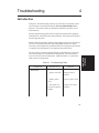
Chapter 4 Troubleshooting.................................................................. 4-1
Introduction ............................................................................................................... 4-1
No Power ........................................................................................................... 4-1
Initialization Failure ............................................................................................. 4-2
Media Does Not Move ........................................................................................ 4-2
Internal ERROR “Carriage Axis Failure” .............................................................. 4-3
xi
NovaJet 500/630/700 Series Service Manual
Table of Contents (cont)
Chapter 4 Troubleshooting (cont)
Internal ERROR “Encoder Sensor Failure” .......................................................... 4-5
Internal ERROR “Paper Sensor Failure” .............................................................. 4-5
Internal ERROR “Auto-Sensor Failure” ................................................................ 4-6
Internal ERROR “MPCB Failure” ......................................................................... 4-6
Unrecognized Cartridges Error ............................................................................ 4-6
Image Skews or Moves ...................................................................................... 4-7
Does Not Print .................................................................................................... 4-7
Ink Cartridge Misfiring ......................................................................................... 4-7
Paper Skewing ................................................................................................... 4-9
Printer Output is Banding (Horizontal) ................................................................ 4-9
Printer Output is Banding (Vertical) .................................................................. 4-11
Printer Output is Banding (Horizontally and Vertically) ...................................... 4-11
Keypad Locked-Up or Not Functioning Properly ............................................... 4-11
Noisy Operation ............................................................................................... 4-12
Line Quality Degraded ...................................................................................... 4-13
Fan Does Not Power Up ................................................................................... 4-14
Media Take-Up Motor Not Operating, Sensor Works ........................................ 4-14
Media Feed Motor Not Operating, Sensor Works ............................................. 4-15
Media Feed and Take-Up Motors Not Operating, Both Sensors Working .......... 4-15
Media Feed or Take-Up Sensor(s) Not Operating .............................................. 4-15
Initialization Troubleshooting (500 Series) ............................................................... 4-18
Initialization Troubleshooting (630/700 Series) ......................................................... 4-20
Chapter 5 Assembly\Disassembly ...................................................... 5-1
Introduction ............................................................................................................... 5-1
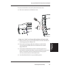
Remove the Left, Top, and Right Covers .................................................................... 5-2
Install the Left, Top, and Right Covers ....................................................................... 5-6
Remove the Keypad and Display .............................................................................. 5-7
Install the Keypad and Display .................................................................................. 5-9
Remove Extra Memory (SIMM) ............................................................................... 5-10
Install Extra Memory (SIMM) .................................................................................. 5-11
Remove the MPCB (Main Printed Circuit Board) ..................................................... 5-11
Install the MPCB .................................................................................................... 5-14
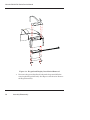
Remove Power Supply, Cooling Fan, and AC Entry Module .................................... 5-15
Install the Power Supply, Cooling Fan, and AC Entry Module ................................. 5-17
xii
NovaJet 500/630/700 Series Service Manual
Table of Contents (cont)
Chapter 5 Assembly/Disassembly (cont)
Remove Servo Motor ............................................................................................... 5-18
Install Servo Motor .................................................................................................. 5-20
Remove the Ink Delivery System ............................................................................. 5-21
Install the Ink Delivery System ................................................................................ 5-23
Remove the Carriage Assembly, Carriage Belt, and the Frame Tensioner ................ 5-24
Install the Carriage Assembly, Carriage Belt, and the Frame Tensioner .................. 5-27
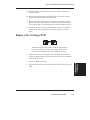
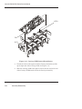
Remove the Carriage PCB ...................................................................................... 5-29
Install the Carriage PCB ......................................................................................... 5-31
Remove the Paper Sensor or the Encoder Sensor .................................................. 5-31
Install the Paper Sensor or the Encoder Sensor ...................................................... 5-33
Replacing the Carriage Bushings ............................................................................ 5-34
Remove the Service Station .................................................................................... 5-36
Install the Service Station ....................................................................................... 5-36
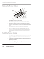
Remove the Trailing Cable Assembly ...................................................................... 5-37
Install the Trailing Cable Assembly ......................................................................... 5-37
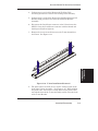
Remove the Stabilizer Bracket and Encoder Strip ................................................... 5-38
Install the Stabilizer Bracket and Encoder Strip ...................................................... 5-40
Remove the Y-Arm Assembly, Pinch Rollers, Slide Shaft, and Auto-Load Sensor ... 5-40
Install the Y-Arm Assembly, Pinch Rollers, Slide Shaft, and Auto-Load Sensor ...... 5-43
Remove the Lower Roller Assembly, Stepper Motor and Vacuum Fan ..................... 5-44
Install the Lower Roller Assembly, Stepper Motor and Vacuum Fan ........................ 5-47
Remove the Media Take-Up and Feed Sensor Brackets and Sensors ..................... 5-50
Install the Media Take-Up and Feed Sensor Brackets and Sensors ........................ 5-52
Remove the Media Take-Up and Feed Motors ......................................................... 5-52
Install the Media Take-Up and Feed Motors ............................................................ 5-54
Remove the Media Drying Fans .............................................................................. 5-54
Install the Media Drying Fans ................................................................................. 5-55
Remove the Thermal Dryer Assembly (NovaJet 750) ............................................... 5-56
Install the Thermal Dryer Assembly (NovaJet 750) .................................................. 5-57
Chapter 6 Parts List .............................................................................. 6-1
xiii
NovaJet 500/630/700 Series Service Manual
List of Illustrations
Figure
Page
Chapter 1 General Description
1-1.
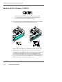
NovaJet 500/630/700 Series Inkjet Printers ..................................................... 1-1
Chapter 2 Theory of Operation
2-1.
2-2.
2-3.
2-4.
2-5.
2-6.
2-7.
2-8.
2-9.
2-10.
2-11.
2-12.
General Block Diagram ................................................................................... 2-2
Paper (Media) Axis Drive ................................................................................. 2-3
Carriage Axis Drive .......................................................................................... 2-4
Power Feed and Take-Up System ................................................................... 2-5
Main Printed Wiring Assembly ........................................................................ 2-6
Gate Array ...................................................................................................... 2-7
Stepper Motor Controller ............................................................................... 2-10
Servo Motor Controller ................................................................................... 2-12
Quadrature Signal Generation ....................................................................... 2-13
Interface Circuits ........................................................................................... 2-14
Carriage Assembly Circuits ........................................................................... 2-15
Main Menu .................................................................................................... 2-16
Chapter 3 Maintenance
3-1.
3-2.
3-3.
3-4.
3-5.
3-6.
3-7.
3-8.
3-9.
3-10.
3-11.
3-12.
3-13.
3-14.
3-15.
3-16.
xiv
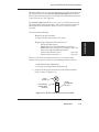
Encoder Strip Cleaning ................................................................................... 3-5
Cartridge Dimple Region .................................................................................. 3-5
Flex Cable Contacts ....................................................................................... 3-6
MPWA Connection Locations ......................................................................... 3-9
Carriage PWA Connection Locations ............................................................ 3-10
Ribbon Connector Locking Mechanism ......................................................... 3-11
Servo Motor ................................................................................................... 3-12
Stepper Motor ............................................................................................... 3-13
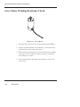
Power Feed and Take-Up Motor .................................................................... 3-14
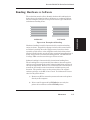
Examples of Banding .................................................................................... 3-15
Dial Gauge Micrometer Assembly ................................................................. 3-19
Measurement Positions for Slide Shaft .......................................................... 3-20
Slide Shaft Profile Adjustment ....................................................................... 3-21
Carrier Head Height Tolerance ....................................................................... 3-22
Setting Up Tools from Height Gauge Kit ........................................................ 3-22
Zeroing the Micrometer Gauge ...................................................................... 3-23
NovaJet 500/630/700 Series Service Manual
List of Illustrations (cont)
Figure
Page
Chapter 3 Maintenance (cont)
3-17.
3-18.
3-19.
3-20.
3-21.
3-22.
3-23.
3-24.
3-25.
3-26.
3-27.
3-28.
3-29.
3-30.
3-31.
3-32.
3-33.
3-34.
3-35.
3-36.
Test Cartridge Installed .................................................................................. 3-23
Support Bracket Placement .......................................................................... 3-24
Color Calibration ............................................................................................ 3-26
Utility Menu ................................................................................................... 3-27
Color Calib Menu ........................................................................................... 3-28
Cyan Vertical Options Menu .......................................................................... 3-28
Slow Deadband ............................................................................................. 3-29
Service Menu ................................................................................................ 3-30
Calibration (Deadband) Menu (500 Series) ..................................................... 3-31
Calibration (Deadband) Menu (630/700 Series) .............................................. 3-31
Calibration Menu ........................................................................................... 3-33
Color Db Menu .............................................................................................. 3-34
Paper Axis Test ............................................................................................ 3-36
Diagnostics Menu ......................................................................................... 3-37
Accessory Menu ........................................................................................... 3-37
NVRAM Clear and Clock Reset Menu ........................................................... 3-40
MPWA Connections Diagram ........................................................................ 3-45
Carriage PWA Connections Diagram ............................................................. 3-46
Leg Harness Connections Diagram ............................................................... 3-47
Leg Harness Connections Diagram (750) ...................................................... 3-48
Chapter 4 Troubleshooting
4-1.
4-2.
Carriage Board LED D2 Location for NJ 500 Series ....................................... 4-19
Carriage Board LED D2 and D5 Location for NJ 630/700 Series .................... 4-21
Chapter 5 Assembly/Disassembly
5-1.
5-2.
5-3.
5-4.
5-5.
5-6.
5-7.
5-8.
Right Cover Assembly Removal/Installation ..................................................... 5-3
Left Cover Assembly Removal/Installation ....................................................... 5-4
Left Cover Assembly Removal/Installation (NovaJet 750) ................................. 5-5
Keypad and Display Removal/Installation ........................................................ 5-8
Keypad and Display Grounding Connection ..................................................... 5-9
Extra Memory (SIMM) Removal/Installation ................................................... 5-10
MPCB Removal ............................................................................................. 5-13
Power Supply Removal ................................................................................. 5-16
xv
NovaJet 500/630/700 Series Service Manual
List of Illustrations (cont)
Figure
Page
Chapter 5 Assembly/Disassembly (cont)
5-9.
5-10.
5-11.
5-12.
5-13.
5-14.
5-15.
5-16.
5-17.
5-18.
5-19.
5-20.
5-21.
5-22.
5-23.
5-24.
5-25.
5-26.
5-27.
5-28.
5-29.
5-30.
Cooling Fan/AC Entry Module Removal ......................................................... 5-17
Slacken Carriage Belt ................................................................................... 5-19
Chain Support Bracket Removal .................................................................... 5-22
Cariage Cover Removal ................................................................................. 5-22
Chain Support Bracket Adjustment ............................................................... 5-24
Strain Relief Removal/Installation .................................................................. 5-25
Frame Tensioner ........................................................................................... 5-26
Carriage Belt Clamp ...................................................................................... 5-26
Carriage PCB Removal/Installation ................................................................ 5-30
Paper and Encoder Sensor Removal ............................................................. 5-32
Paper and Encoder Sensor Installation .......................................................... 5-33
Carriage Bushing Removal ............................................................................ 5-35
Carriage Bushing Installation ......................................................................... 5-35
Service Station Removal ................................................................................ 5-36
Stabilizer Bracket Installation/Removal .......................................................... 5-39
Y-Arm Installation/Removal ........................................................................... 5-41
Pinch Roller .................................................................................................. 5-42
Stepper Motor Removal/Installation ............................................................... 5-47
Inside Platen, Right Side ............................................................................... 5-49
Media Take-Up and Feed Sensor Removal .................................................... 5-51
Media Take-Up and Feed Motor Removal ...................................................... 5-53
Inner Platen Assembly/Disassembly ............................................................. 5-57
Chapter 6 Parts List
6-1.
6-2.
6-3.
6-4.
6-5.
6-6.
6-7.
6-8.
6-9.
6-10.
xvi
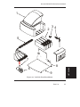
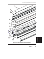
Left Side Parts Breakdown .............................................................................. 6-3
Left Side Parts Breakdown (NovaJet 750) ........................................................ 6-5
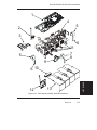
Platen and Above Parts Breakdown ................................................................ 6-7
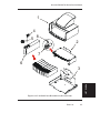
Right Side Parts Breakdown ........................................................................... 6-9
Right Side Parts Breakdown (NovaJet 750) ................................................... 6-11
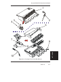
Inner Platen Parts Breakdown ....................................................................... 6-13
Carriage Assembly Parts Breakdown ............................................................ 6-15
Carriage Cover Parts Breakdown ................................................................... 6-17
Service Station Parts Breakdown .................................................................. 6-19
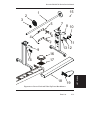
Power Feed and Take-Up Parts Breakdown ................................................... 6-21
NovaJet 500/630/700 Series Service Manual
List of Tables
Table
Page
Chapter 1 General Description
Chapter 2 Theory of Operation
Chapter 3 Maintenance
3-1.
3-2.
MPWA Connections Table .............................................................................. 3-9
Carriage PWA Connections Table ................................................................. 3-10
Chapter 4 Troubleshooting
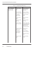
4-1.
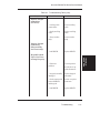
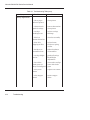
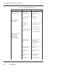
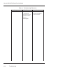
Troubleshooting Table ...................................................................................... 4-1
Chapter 5 Assembly/Disassembly
Chapter 6 Parts List
xvii
NovaJet 500/630/700 Series Service Manual
This Page Intentionally Left Blank
xviii
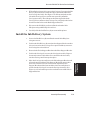
General Description
1
GENERAL
DESCRIPTION
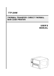
Figure 1-1. NovaJet 500/630/700 Series Inkjet Printers.
Introduction
This manual provides service information for the ENCAD®, Inc.
NovaJet® 500, NovaJet 630 and the NovaJet 700 Series of Color
Inkjet Printers. The NovaJet 500 series includes the NovaJet 500 and
NovaJet 505 printers. The NovaJet 700 series includes the NovaJet
700, NovaJet 736 and NovaJet 750 printers. All three NovaJet 500/
630/700 printer series comes in two sizes: a 42 inch model and a 60 inch
model. The NovaJet 736 printer comes only as a 36 inch model.
The service manual is written for service personnel who possess analog
and digital circuitry experience. Chapter 2, Theory of Operation, should
1-1
NovaJet 500/630/700 Series Service Manual
be read and thoroughly understood before troubleshooting/calibrating
the printers.
The printers support pre-cut and roll media. Media size is automatically determined and hardclip limits are set accordingly. Pre-cut media
uses different maximum plotting areas than roll media. See the Printer
Specifications in the User Guide for more details on the media size
printable area.
Both RS-422 serial and Centronics parallel connections are provided to
interface with the host computer. For proper operations, the NovaJet
750 must be connected to a 100BaseT network print server. Commands
sent from the host computer can be in several forms including HP-GL/
2, HP-RTL and EN RTL formats.
Drivers are supplied to support Windows-based PC’s (3.XX, 95/98, and
NT) as well as Macintosh and Power PC computers.
These printers expand upon ENCAD’s tradition of delivering fast, highquality color or monochrome graphics for a variety of applications.
ENCAD has made significant advances in designing these printers to
respond to and anticipate our customers’ needs. Principal features are
summarized below.
Locally or Remotely Configured via Host Computer
Powered Media Take-Up and Feed System (700 series only)
Powered Feed Roll and Take-Up Basket (500 & 630 series)
Optional Powered Take-Up Roll System (500 & 630 series)
Media Drying System (optional on the 500 & 630 series)
Thermal Media Drying System (NovaJet 750)
Quick Ink Changeover
Self-Aligning Pinch Rollers
PowerPC 33 MHz Microprocessor
8 User Configurable Settings
104 Jet Ink Cartridges (500 series)
208 Jet Ink Cartridges (630 & 700 series)
Ink Priming System
4 500ml Ink Reservoirs (8 for the NovaJet 750)
Smart Cartridges
Odometer Function
Improved Septum Connector Design
1-2
General Description
NovaJet 500/630/700 Series Service Manual
Overview
Related Publications
The following publication contains additional information which may
be useful in servicing the ENCAD, Inc. NovaJet 500/630/700
Series Color Inkjet Printers:
•
ENCAD NovaJet 500/630/700 Quick Start Guide,
P/N 212528-04
•
ENCAD NovaJet System CD-ROM,
P/N 212532-02
Copies of these and other ENCAD, Inc. publications may be obtained by contacting your nearest authorized ENCAD, Inc. dealer or
by contacting ENCAD’s Technical Support and Service Department.
Electrostatic Discharge (ESD) Sensitivity
All PWAs (Printed Wiring Assemblies) associated with the NovaJet
500/630/700 series printers have components sensitive to ESD
(electrostatic discharge). Care must be taken to avoid damage to any
of the components by following current ESD handling procedures and
practices.
Always use an approved ESD grounding strap when handling or
working with PWAs.
General Description
1-3
GENERAL
DESCRIPTION
Printers draw according to instructions issued from a “host” computer. Every printer is engineered to understand a specific set of
instructions and to execute each instruction in a precise manner. In
addition, most printers are designed to execute predetermined
characters automatically without a specific line-by-line instruction
from the program. These characters are part of the printer’s permanent memory.
NovaJet 500/630/700 Series Service Manual
Warnings, Cautions and Notes
Warnings, cautions and notes are used when additional information,
instructions or care should be observed. In this manual warnings,
cautions and notes precede the text to which each applies. The definition of each is provided below.
WARNINGS - Warnings are used to stress that the following steps or
procedures has the potential to cause serious harm or death to service
personnel. Extreme care should be observed when following the procedures and to exercise standard safety procedures. They are indicated
by:
WARNING
Followed by a paragraph describing the concern.
CAUTIONS - Cautions depict that the following steps or procedures can
cause damage to the equipment if not properly followed. Extreme care
should be observed when following the procedures and to exercise
standard safety procedures. They are indicated by:
CAUTION
Followed by a paragraph describing the concern.
NOTES - Notes are placed before a procedure to inform the service
personnel of specific details to improve quality, to give reminders of
interrelated parts and to provide other helpful information. They are
indicated by:
NOTE
Followed by a paragraph describing the concern.
1-4
General Description
NovaJet 500/630/700 Series Service Manual
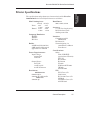
Printer Specifications
GENERAL
DESCRIPTION
The specifications and performance characteristics of the NovaJet
500/630/700 Series Color Inkjet Printers are as follows:
Max Printing Area:
42 inch 60 inch
Norm
40.8”
58.8”
1.04m
1.49m
Extend 41.61”
59.61”
1.06m
1.51m
Language Emulation:
HP-RTL
EN RTL
HP GL/2
Buffer:
32 MB installed (630/700)
8 MB installed (500 series)
upgradeable to 128 MB
Power Requirements:
Input Voltage:
90-264 VAC
48-63 Hz
Output Power:
20 W idle
140 W typical
215 W maximum
Resolution:
630/700 series
600x600 dpi or
300x300 dpi, addressable
500 series
300x300 dpi
Baud Rates:
9600, 19200, 38400
Accuracy:
+/- 0.2% line length using
ROLL feed and 4 mil
drafting matte film
Interface:
Centronics parallel
(IEEE 1284)
RS-422 serial
Network Option: via
10/100BaseT, 10Base2
Print Server
Certifications:
Safety
CSA, CSE/NRTL
(equivalent to UL1950)
TUV GS
EN 50 082-1
EN 60 950
UL1950
NOM-019-SCFI-1993
IEC 950
AS/NZS 3260
EMI
FCC Class A, B
CSA C108.8
EN 55 022 Class A, B
CE Mark
CISPR 22- Class A, B
AS/NZS 3548
General Description
1-5
NovaJet 500/630/700 Series Service Manual
Environment:
Operating:
59° to 95° F
(15° to 35° C)
10% to 70% RH
non-condensing
Weight:
60” 88 lbs 135 lbs (boxed)
42” 72 lbs 117 lbs (boxed)
Dimensions:
Height 44” (1.12m)
Storage:
-5° to 140° F
(-21° to 60° C)
5% to 80% RH
non-condensing
Width 77” (1.96m)
42 inch
95” (2.41m)
60 inch
Depth 28” (0.71m)
Contents of this Service Manual
Figures are used in this manual to clarify procedures. They are for
illustrative purposes only and may not necessarily be drawn to scale.
Material in this manual may be repeated in various chapters so that
each chapter can “stand alone”. This allows information to be located
without having to refer back and forth between chapters.
Figures and tables are easily located and cross-referenced, and are listed
in the front of the manual under List of Illustrations and List of Tables.
This manual is divided into six chapters as:
Chapter 1 GENERAL DESCRIPTION - Contains a general
description of the ENCAD NovaJet 500/630/700 printers.
This includes printer specifications, and related materials.
Also included is a description of the use of Warnings,
Cautions and Notes as used in this manual and chapter
contents.
1-6
General Description
NovaJet 500/630/700 Series Service Manual
GENERAL
DESCRIPTION
Chapter 2 THEORY OF OPERATION - Functional
descriptions of the overall printer and major assemblies
are contained in this chapter.
Chapter 3 MAINTENANCE - This chapter covers the
scheduled maintenance, cleaning procedures and
alignment/adjustments recommended to perform on the
printers. Diagnostics and a signal flow diagram are also
listed.
Chapter 4 TROUBLESHOOTING - A table containing
problems that could occur and possible causes and repairs
is found in this chapter. This table is not intended to be a
complete listing of troubleshooting procedures. It will
isolate the problem down to the lowest replacable
assembly. If the problem happens to be the wiring
between assemblies, standard troubleshooting techniques
will have to be implemented to correct the problem.
Chapter 5 ASSEMBLY/DISASSEMBLY - Contains detailed
procedures to remove and replace printer parts and
assemblies.
Chapter 6 PARTS LIST - Contains a complete listing of all
field replacable parts and assemblies for the NovaJet 500/
630/700 Color Inkjet Printers. Illustrated parts
breakdown drawings are included to help clarify and
identify parts for ordering. Special kits and adjustment
jigs may also be required.
ORIENTATION - Instructions in this manual are based on the
assumption that the service person is facing the front of the printer.
References to top view, back view, and so forth are consistent with
this engineering standard. References to the X Axis and Y Axis
(Paper Axis and Carriage Axis, respectively) follow the standard of
AutoCAD™ absolute coordinates: up and down for X, left to right for
Y.
General Description
1-7
NovaJet 500/630/700 Series Service Manual
Technical Support
ENCAD offers full technical support and service for its various products. If you are unable to find the answer to your question in either the
User’s Guide, Service Manual, or other related publications, check out
ENCAD’s Knowledge Base located on ENCAD’s website support:
ENCAD Website:
http://www.encad.com
Additional information is available though our Technical Support and
Service Department’s Help Desk.
ENCAD, Inc.
Technical Support & Service Dept.
6059 Cornerstone Court West
San Diego, CA 92121
Help Desk Telephone:
Help Desk FAX:
(858) 452-4350 or
(877) ENCAD-TS (362-2387)
(858) 558-4672
International users contact your local ENCAD service provider. See
details on your ENCAD registration card.
1-8
General Description
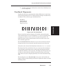
Theory of Operation
2
Introduction
This chapter explains the mechanical and electrical theory of operation
of the ENCAD NovaJet 500/630/700 Series Color Inkjet printers.
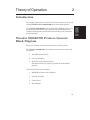
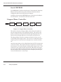
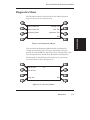
NovaJet 500/630/700 Printers General
Block Diagram
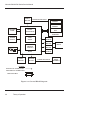
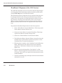
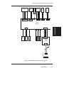
Figure 2-1 illustrates the major functional areas of the printers.
The NovaJet 500/630/700 Series printers consist of three mechanical
assemblies:
1. Paper (Media) Axis Drive
2. Carriage Axis Drive
3. Media Feed and Take-Up System
(Mechanical Take-Up system is optional on the 500 & 630
printers.)
and four main electrical assemblies:
1. MPCB (Main Printed Circuit Board)
2. Carriage Assembly
3. Control Panel
4. Power Supply
2-1
THEORY OF
OPERATION
The NovaJet 500/630/700 Series is a PowerPC 33MHz microprocessorbased digital printer that receives plotting instructions from a host
computer through either the RS-422 serial interface or the Centronics
parallel interface.
NovaJet 500/630/700 Series Service Manual
SERVO
MOTOR
CARRIAGE AXIS DRIVE
PAPER
SENSOR
ENCODER
SENSOR
CONTROL
PANEL
CARRIAGE
PCB
MICROPROCESSOR
CARRIAGE
ASSEMBLY
GATE
ARRAY
POWER
SUPPLY
FEED
SENSOR
FEED
MOTOR
PRINT
SERVER
MEMORY
CIRCUITS
TAKE-UP
MOTOR
MPWA
TAKE-UP
SENSOR
STEPPER
MOTOR
PAPER AXIS DRIVE
LEGEND
ELECTRICAL CONNECTION
MECHANICAL CONNECTION
MAIN DATA BUS
Figure 2-1. General Block Diagram.
2-2
Theory of Operation
MEDIA
LOWER
DRIVE
ASSEMBLY
NovaJet 500/630/700 Series Service Manual
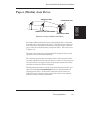
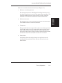
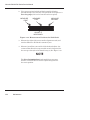
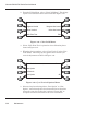
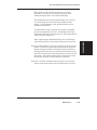
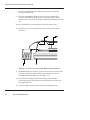
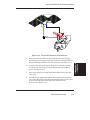
Paper (Media) Axis Drive
PINCH ROLLERS
STEPPER MOTOR
THEORY OF
OPERATION
LOWER ROLLER SHAFT ASSY
REDUCTION GEAR
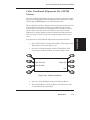
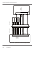
Figure 2-2. Paper (Media) Axis Drive.
The Paper (Media) Axis Drive moves the plotting media in a direction
perpendicular to the length of the printer. This friction drive utilizes a
micro-step drive technology and consists of a stepper motor, reduction
gears, lower drive shaft assembly, and pinch rollers. This can be seen
in Figure 2-2.
The micro-step technology associated with the stepper motor gives the
capability of a resolution up to 9600 dpi.
The reduction gear meshes the stepper motor to the lower drive shaft
assembly which allows the media to advance or retract. The purpose of
the pinch rollers is to apply pressure to the media onto the drive shaft
assembly to reduce the chance of slipping.
Misaligned pinch wheels is a main cause of skewing of the media. For
that reason the NovaJet 500/630/700 Series was designed with self
aligning pinch rollers. As the media is fed forward, the rollers are
aligned correctly. However, these pinch rollers will not stay aligned
while the media is being fed backwards.
Theory of Operation
2-3
NovaJet 500/630/700 Series Service Manual
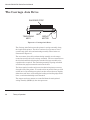
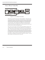
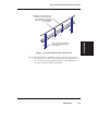
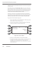
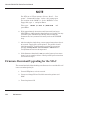
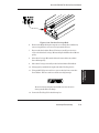
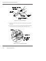
The Carriage Axis Drive
ENCODER STRIP
TENSIONING
ASSY
BELT
SERVO
MOTOR
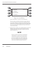
Figure 2-3. Carriage Axis Drive.
The Carriage Axis Drive moves the printer’s carriage assembly along
the length of the printer. The drive consists of a servo motor, linear
encoder strip, drive belt, and tensioning assembly. These items are
illustrated in Figure 2-3.
The servo motor, drive belt, and tensioning assembly are the components that actually drive the carriage assembly. The servo motor drives
the belt back and forth allowing the attached carriage assembly to be
repositioned as required. The tensioning assembly is spring controlled
and allows the proper amount of tension on the belt.
The linear optical encoder strip is used to obtain the printers accuracy
along the axis of the printer. It is made with 150 parallel lines per inch
etched into it. By utilizing two optical encoder sensors that are slightly
offset from each other, and reading the leading and trailing edges of the
lines, a resolution of 600 dpi can be obtained.
The stepper and servo motors are controlled from the main printed
wiring assembly (MPWA) by the microprocessor.
2-4
Theory of Operation
NovaJet 500/630/700 Series Service Manual
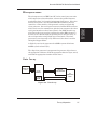
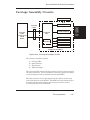
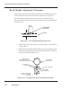
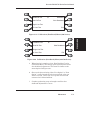
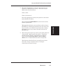
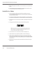
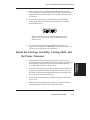
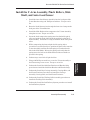
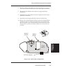
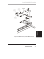
Media Feed and Take-Up System
SENSORS
REFLECTOR
THEORY OF
OPERATION
REFLECTOR
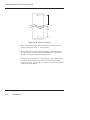
Figure 2-4. Power Feed and Take-Up System.
The media feed and take-up system comprises of two optical sensors,
two dc motors and a dryer assembly. See Figure 2-4. The NovaJet
750 uses a thermal drying system while all other models use a blower
drying system as shown above.
Motors are used to advance the media feed roll and the media take-up
roll dependant upon the signals they receive from the MPWA. The
MPWA generates the control signals for the motors from the information it receives from the media feed and take-up sensors. The MPWA
also controls the dryer assembly. It activates only the fans required to
cover the width of the loaded media. The fan assembly also contains an
interlock circuit.
The optical sensors are designed to inform the MPWA when there is not
a proper amount of slack in the media by sensing the ‘curl’ of the media
at the bottom of its loop. This method is used so that all approved forms
of media (including transparent backlit media) is able to take advantage
of the power feed and take-up system.
Theory of Operation
2-5
NovaJet 500/630/700 Series Service Manual
Main Printed Wiring Assembly (MPWA)
CRYSTAL
X1
STEPPER MOTOR
CONTROLLER
CARRIAGE
PWA
FLASH
EEPROM
CONTROL
PANEL
MICROPROCESSOR
(CPU)
DATA BUS
SERIAL
EEPROM
DYNAMIC
RAM
(SIMM)
GATE
ARRAY
SERVO MOTOR
CONTROLLER
MEMORY CIRCUITS
SERIAL
INTERFACE CIRCUITS
PARALLEL
Figure 2-5. Main Printed Wiring Assembly.
The Main Printed Wiring Assembly (MPWA) consists of six functional
areas:
2-6
1.
Microprocessor (CPU)
2.
Gate Array
3.
Memory Circuits
4.
Stepper Motor Controller
5.
Servo Motor Controller
6.
Interface Circuits: Serial & Parallel
Theory of Operation
NovaJet 500/630/700 Series Service Manual
Microprocessor
A divide-by-two circuit generates the 33MHz system clock from a
66MHz crystal reference (X1).
The chip select generator is programmed to generate chip selects at
the appropriate addresses, with the appropriate data size (byte, word)
and with the appropriate number of wait states.
Gate Array
PARALLEL
PORT
GATE
ARRAY
SERVO
CONTROLLER
STATIC
RAM
TO
CARRIAGE
PWA
Figure 2-6. Gate Array.
Theory of Operation
2-7
THEORY OF
OPERATION
The microprocessor (an IBM PowerPC) is the central processor unit
which supervises system functions, executes the printer firmware,
manipulates data, and controls input/output data busses. It has two
built-in serial ports, a two channel DMA (Direct Memory Access)
controller, a timer module, clock generator, and an on-board chip
select generator. One serial port connects to the Mini-DIN connector
which can be used to communicate with the host computer; the other
serial port interfaces to the Control Panel. One DMA channel supplies data to the gate array for jet firing; the other DMA channel is
used to receive data through the parallel port via the gate array, or
the serial port when using a high speed serial mode. One timer
generates a servo interrupt every millisecond; the other is used for
timing the Stepper Motor.
NovaJet 500/630/700 Series Service Manual
The gate array contains the hardware logic for jet firing, monitoring
changes in the Carriage Assembly position, controlling DMA through
the parallel port, and generating the PWM (Pulse Width Modulation)
waveforms for the servo controller.
The gate array is a Xilinx device. It is a static RAM-based field programmable gate array. This means that the logic that it implements is
determined by configuration information in an internal RAM storage
area. Each time power is turned on, this information must be downloaded from the system EEROM. This type of gate array allows for the
flexibility of upgrading the logic by simply downloading the new system
software.
Memory Circuits
Memory is used to retain large amounts of information. This information is stored in the device memory in the form of binary bits.
Printer memory consists of Flash EEPROM, DRAM, and EEPROM.
Maximum installable memory is as follows:
DRAM = 128 MB
Flash EEPROM = 1 MB
Serial EEPROM = 1KB
Flash EEPROM
Flash EEPROM is Electrically Erasable, Programmable, Read Only
Memory used to store instructions and data constants which the
microprocessor can access and interpret, with no loss of information
when power is off.
2-8
Theory of Operation
NovaJet 500/630/700 Series Service Manual
The system firmware is stored in Flash EEPROM. The Flash
EEPROM allows the firmware to be upgraded by downloading the files
containing the new firmware. It can be erased and reprogrammed
more than 10,000 times. The term “Flash” means that bytes cannot be
individually erased. A block or the whole device is erased at the same
time and the block or whole device is then reprogrammed.
DRAM
DRAM is Dynamic Random Access Memory which provides temporary
storage of the microprocessor calculation and input/output data. It is
also a faster type of memory then the Flash EEPROM. That’s why the
printer control program is also copied from the Flash EEPROM to
RAM, where it can be executed faster.
The printer also has two 72-pin 32-bit SIMM sockets for DRAM. The
printer is supplied with a SIMM installed on the MPWA. The SIMM
size for the 500 series is 8 Megabyte and for the 630/700 series is 32
Megabyte. The following SIMM sizes are supported: 4MB (1Mx32),
8MB (2Mx32), 16MB (4Mx32), 32MB (8Mx32) and 64MB (16Mx32.)
The SIMMs must have a minimum operating speed of 70ns, and
conform to JEDEC Standard 21-D release 4 or later. Remove the Right
Cover to install additional memory (see Chapter 5 for installation
procedures.) Care must be taken when choosing a SIMM module for
the printer. Not all SIMM’s on the market today will work on the
printer. It has to do with the “presence detect” signals on pins 67 and
68 of the SIMM’s. Not all SIMM manufacturers use these signals, so
they disable them.
Theory of Operation
2-9
THEORY OF
OPERATION
The normal method of downloading new firmware is to send the unit
the files containing the code using either the GO.EXE utility or printing the file to the unit. This requires using an appropriate host utility
and can be done through the serial port (for Macintosh users) or the
parallel port (for PC users). See Firmware Downloading in Chapter 3
for the procedures.
NovaJet 500/630/700 Series Service Manual
Serial EEPROM
Serial EEPROM is an Electrically Erasable, Programmable, Read Only
Memory which provides storage for calibration constants and user
configuration data entered from the host computer.
An 8K bit serial nonvolatile EEPROM stores calibration and configuration information. It retains data while the unit is off.
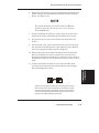
Stepper Motor Controller
DATA BUS
WAVEFORM
GENERATOR
COMPARATOR
DRIVER
CURRENT
SENSE
STEPPER
MOTOR
Figure 2-7. Stepper Motor Controller.
The media is driven by a Stepper Motor, which drives the media in a
direction perpendicular to the width of the printer. The media in the
printer can advance forward and backward, depending upon the commands which the Stepper Motor receives from the microprocessor.
The Stepper Motor Controller contains two identical circuits, one for
each winding of the stepper motor. The circuit is a combination of two
simpler types of circuits and can be thought of as a variation of either
one.
A waveform generator receives digital data from the CPU and generates
a sine wave output. This signal is fed into a comparator circuit that is
measuring the current through the winding of the stepper motor. If the
current is too low, a pulse of 24V is generated. When the current goes
above the output of the waveform generator, the pulse turns off. Every
time the output of the waveform generator is changed by the microprocessor, the motor moves 1 “micro-step”.
2-10
Theory of Operation
NovaJet 500/630/700 Series Service Manual
Each circuit contains four main functions (see Figure 2-7):
1. Reference waveform generator
The microprocessor uses a D/A (digital to analog) converter to set
the desired level for the current in the stepper motor winding. The
output of the D/A converter varies in time to create a reference
waveform. This reference waveform is centered around 10V.
The voltage across a series current sense resistor is measured and
level shifted so that it is centered around 5V.
3. Comparator
This portion divides the output of the reference waveform generator
by two and compares it to the output of the motor current sensor.
Logic inside the gate array generates the control signals for the
power driver that applies voltage across the motor winding in order
to make the actual current match the reference waveform.
4. Power driver
An H-bridge allows the supply voltage to be applied across the
winding in either polarity used to drive the current level to the
desired value.
Theory of Operation
2-11
THEORY OF
OPERATION
2. Motor current sense
NovaJet 500/630/700 Series Service Manual
Servo Motor Controller
ENCODER
GATE
ARRAY
MOTOR
DRIVER
SERVO
CONNECTOR
SERVO
MOTOR
CARRIAGE
CONNECTOR
CARRIAGE
MAIN PWA
Figure 2-8. Servo Motor Controller.
The Carriage Assembly is driven by the Servo Motor. The speed of the
Carriage Assembly is controlled by varying the duty cycle of the signal
applied to the controller. The microprocessor checks the position of the
Carriage Assembly approximately 1,000 times per second (during the
servo interrupt). It then updates the PWM (pulse width modulator)
register in the gate array which sets the duty cycle to make adjustments to the Carriage Assembly speed. A linear optical encoder is used
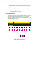
to monitor the Carriage Assembly position.
The optical encoder strip runs the length of the Stabilizer Bracket and
contains 150 lines and spaces per inch. Thus there are 300 edges per
inch. The detector circuit actually consists of two optical edge detectors.
They are separated from each other by one half the width of one of the
optical lines on the encoder strip. This allows 4 evenly spaced pulses to
be developed for each line on the encoder strip. This is known as quadrature signals. It gives an effective resolution of 600 lines per inch. See
figure 2-9 for a graphical representation of quadrature signals. For 300
dpi resolution, one of the detectors is not used.
2-12
Theory of Operation
NovaJet 500/630/700 Series Service Manual
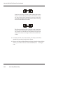
DETECTOR 2
DETECTOR 1
ENCODER STRIP
THEORY OF
OPERATION
OUTPUT OF DETECTOR 1
OUTPUT OF DETECTOR 2
COMPOSITE TRANSITION-TRIGGERED OUTPUT OF BOTH DETECTORS
4 OUTPUT PULSES
PER OPTICAL LINE
Figure 2-9. Quadrature Signal Generation.
The direction that the Carriage Assembly is moving is known based
upon the state of one detector’s output and the direction of the transition
of the other detector’s output.
A hardware counter in the gate array increments as the Carriage
Assembly moves left and decrements as the Carriage Assembly moves
right. The hardware counter is only eight bits wide, so it cannot store a
value large enough to represent an absolute Carriage Assembly position.
Instead, it is read during the servo interrupt and its value compared
with that from the previous interrupt. This difference is used to update
the absolute position value in the software.
Theory of Operation
2-13
NovaJet 500/630/700 Series Service Manual
Interface Circuits: Serial & Parallel
SERIAL
CONNECTOR
TRANSCEIVER
MICROPROCESSOR
GATE
ARRAY
PARALLEL
CONNECTOR
Figure 2-10. Interface Circuits.
Data from the host computer is received either through the Centronics
parallel port or the serial port. The gate array provides the control
signals for DMA transfers from the parallel port to DRAM.
The serial port is designed primarily to interface to a Macintosh®
computer. It has an eight pin Mini-DIN connector. The data (TXD,
RXD) signals meet RS-422 electrical specifications, and the control
signal (DTRCLK) meets the RS-423 electrical specifications.
Due to the data flow speed limitations of using the serial interface with
a Macintosh computer system ENCAD does not recommend using this
port for production usage with the new printers. Hesitation may result
if using this port and that can degrade the quality of the output print.
Possible solutions for the Macintosh computer user include using a
print server device with an established network or installing a parallel
port add-on card in the computer to interface with the printer.
The serial port is still required to download new firmware to the printer
with a Macintosh computer.
The serial port is compatible with RS-422 devices when an appropriate
adapter cable is used. This cable is available from ENCAD.
The NovaJet 750 printer ships with a high speed print server that
attaches to the parallal port for network compatibility.
2-14
Theory of Operation
NovaJet 500/630/700 Series Service Manual
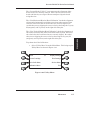
Carriage Assembly Circuits
OPTICAL ENCODER
OPTICAL SENSOR
TRAILING
CABLE
CONNECTION
FROM
MPWA
CARRIAGE
PWA
THEORY OF
OPERATION
TRAILING
CABLE
PAPER SENSOR
CARTRIDGE 1
INKJET
DRIVERS
CARTRIDGE 2
CARTRIDGE 3
CARTRIDGE 4
CARRIAGE ASSEMBLY
Figure 2-11. Carriage Assembly Circuits.
The Carriage Assembly contains:
1)
2)
3)
4)
Carriage PWA
Optical Sensors
Paper Sensor
Inkjet Cartridges
The Carriage PWA contains the logic and drive circuitry for the firing of
the inkjet cartridges. It also establishes an interface path for the optical
sensor and paper sensor to communicate with the MPWA.
The optical sensors receive their inputs from the optical encoder strip
and sends this data to the MPWA. The MPWA uses this information to
determine the horizontal position of the carriage assembly so that
accurate printing can be established.
Theory of Operation
2-15
NovaJet 500/630/700 Series Service Manual
The paper sensor circuitry senses for the presence of loaded media. It
does this automatically during the start-up and load sequences. It also
constantly monitors the media during printing to determine if the
media has run out.
If no paper is sensed, the paper sensor sends this information to the
MPWA, which immediately begins an ‘out of paper’ subroutine. This
subroutine stops the printer from printing until more media is loaded.
The sensor also checks for the size of the media loaded so it can determine the proper printing parameters.
Control Panel
The Control Panel is located on the right side of the printer and consists
of 8 variable-action control buttons and an LCD graphics display. The
control buttons are assigned to different functions and are dependant
upon the selections that were previously selected. There are four buttons
on the left of the display and four buttons on the right, with the display
showing up to eight possible selections.
Load Media
Cut
Pause
*
Feed Media Menu
Setup Menu
Utility Menu
Reset
Figure 2-12. Main Menu.
Figure 2-12 shows the control panel after the printer has been turned on
and completed the start up process. As seen in the figure, the control
buttons are assigned to the corresponding command that is displayed
closest to the physical location of the button.
2-16
Theory of Operation
NovaJet 500/630/700 Series Service Manual
Power Supply
The power supply is fused using a 6.3A 250V fast blow type fuse.
The outputs share a common ground which is isolated from earth
ground with in the supply itself. Earth ground and DC ground are
connected external of the power supply.
The power supply will shut down under overload/short circuit conditions on any output over the full range of input voltage. Overvoltage
protection is 20%-30% above nominal for the 24V output.
Beeper and Fans
The beeper contains built-in driver circuitry so that it beeps under
firmware control. The beeper alerts the user to error conditions.
There exists three types of fans that can be on the NovaJet 500/630/
700 series printers.
A single fan, located behind (below for the NovaJet 750) the power
supply, is used for cooling the power supply. Air blows over the power
supply and the heated air is forced out of the printer.
A fan is located inside the platen with its fan vent seen from under
the platen on the right side of the printer. This fan provides suction
on the platen bed and holds the paper (media) flat during the printing
process. The 60 inch model has an additional suction fan located near
the center of the printer inside the platen.
Theory of Operation
2-17
THEORY OF
OPERATION
An internal UL recognized switching power module supplies power for
the NovaJet 500/630/700 Series printers. It provides a constant
24VDC output from input voltage in the 90-132 VAC and 180-246 VAC
ranges. A power switch turns the power on and off. The 24VDC is
applied to the MPWA where it is further regulated and separated into
24VDC, 13VDC, and 5VDC. The 24V supply is used for: the stepper
controller (which advances the paper); the servo controller (which
moves the Carriage); and power to fire the inkjets. The 5V supply
powers the logic circuits.
NovaJet 500/630/700 Series Service Manual
On the NovaJet 500/505/630/700 printers a media drying fan assembly
is attached to the lower part of the printer legs that is used to speed up
the drying time of the ink that is deposited onto the media. This is to
ensure that the ink is completely dry before the media is rolled onto the
take-up reel. The 42 inch model has five drying fans, while the 60 inch
version has seven.
The drying fan assembly has been designed to keep power consumption
down to a minimum by only activating the amount of fans that are
required to dry the size of media that is loaded on the printer.
The fans will not actually engage until a print command is first established. This commmand can be from a sent print job or any onboard
commands that require printing to complete that function. The fans
will automatically shutdown approximately 20 minutes after the print
is complete.
The drying assembly can also be disabled through the printers firmware
via the control panel.
This drying fan assembly is part of the mechanical take-up system that
is optional on the NovaJet 500 and 630 series printers.
On the NovaJet 750 printers a thermal media drying assembly is used
instead of the fan assembly as on the other models. It accepts control
commands from the MPWA that turns the heating elements on and off.
It also has two fans located underneath the plenum to push the heated/
unheated air out of the holes facing the platen to dry the media. The
drying assembly can be operated with or without the heating elements
being turned on.
2-18
Theory of Operation
Maintenance
3
Introduction
This chapter contains general maintenance and cleaning instructions
for the NovaJet 500/630/700 printers.
Scheduled Maintenance
Scheduled maintenance consists of a list of checks that are planned to
be performed on a regular basis or when conditions warrant it.
Below is a list of scheduled maintenance checks and their recommended periodicity.
Clean external areas:
Clean service station:
Clean cartridge jet area & dimples:
Clean slide shaft:
Clean encoder strip:
Clean flex cable contacts:
Clean Y-Arm surface:
Clean cutter groove:
Clean pinch/lower roller:
Clean platen vacuum holes:
Clean dryer plenum (body) - NJ 750 only:
Clean paper sensor:
Clean and inspect motor gears:
Clean and inspect MPWA:
Clean and inspect carriage assembly:
Reseat connectors on MPWA:
Reseat connectors on carriage board:
Replace carriage bushings:
as required
20-30 plot hours
50-60 plot hours
75-100 plot hours
75-100 plot hours
75-100 plot hours
75-100 plot hours
75-100 plot hours
75-100 plot hours
100-125 plot hours
100-125 plot hours
as required
annually
annually
annually
annually
annually
3000 plot hours
3-1
MAINTENANCE
Scheduled maintenance can be thought of as preventive maintenance
since its purpose is to prolong the life of the printer. It is not intended
to repair or isolate an existing problem, though it can sometimes be
helpful in detecting a condition due to a weakened component that has
not yet completely failed.
NovaJet 500/630/700 Series Service Manual
Cleaning Procedures
WARNING
Always turn the printer OFF, remove the power cord and
the interface cable before cleaning the printer. An electrical shock hazard may be present if these procedures are
not followed.
External Cleaning
CAUTION
Do not use abrasive cleansers of any sort on the surfaces
of the printer. Damage to the surface may result.
The exterior surfaces of the printer may be cleaned with a soft cloth
which has been dampened. For more persistent stains, a small amount
of liquid detergent or NovaKlean™ may be used. Cleaning intervals are
determined by the environment in which the printer is used.
Service Station Cleaning
Ink and dust may build up on the service station, resulting in contamination which may smear the prints. The service station is cleaned as
follows:
1. Turn the printer OFF. Disconnect the power cord and interface
cable.
2. Raise the printer lid.
3. Carefully move the carriage toward the center of the printer.
3-2
Maintenance
NovaJet 500/630/700 Series Service Manual
4. Using a cotton swab dampened with water, wipe the seals and
the rubber wiper in the service station until no more ink
residue or dust can be removed.
5. With a dry swab, wipe all moisture from the seals and wipers.
6. Close the lid and reconnect the power cord and interface cable.
7. If the service station is filling with ink or very dirty it can be
removed and rinsed under warm water. To remove, pull the
tab on the right side of the service station and lift out. Wash,
dry thoroughly and replace by placing the left side in first then
pushing down on the right side until the tab locks it in place.
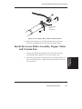
Slide Shaft Cleaning
MAINTENANCE
CAUTION
Use only NovaKlean™ or isopropyl alcohol on the slide
shaft of the printer. Damage to the stainless steel slide
shaft may result if cleaned with water and not completely
dried off.
Printer problems can be caused by an accumulation of dirt or other
contamination on the slide shaft. This contamination may lead to drag
on the carriage. Extreme drag results in a “carriage axis failure” fault
and will stop the carriage motion. These problems may be eliminated
by maintaining and cleaning the slide shaft at intervals determined by
the environmental conditions. Do not use any lubrication.
To clean the slide shaft:
1. Turn the printer OFF. Disconnect the power cord and
interface cable.
2. Raise the printer lid.
3. Moisten a clean cloth or paper wipe with NovaKlean™.
Maintenance
3-3
NovaJet 500/630/700 Series Service Manual
4. Wipe the length of the slide shaft with the moistened cloth or
wipe.
5. Manually move the carriage assembly from side to side.
6. Wipe the shaft again to remove any deposits left from the
carriage.
7. Close the cover and reconnect the power cord and interface
cable, turn the printer ON and perform the PRIME procedure.
Be sure that the carriage moves freely on the slide shaft.
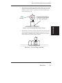
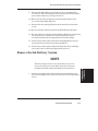
Linear Encoder Strip Cleaning
Clean the linear encoder strip every 75 - 100 plot hours (every 50 plot
hours if GO ink is being used) or as necessary to remove any buildup of
debris. NovaKlean™ followed by isopropyl alcohol should be used. You
may notice that it tends to fog the encoder strip; however, no detrimental effect has been observed in the field.
To clean the Encoder Strip:
1. Disconnect the power cord and interface cable.
2. Slightly dampen a cotton swab with NovaKlean™ and wipe
along the length of the encoder strip on both sides.
3. Slightly dampen a cotton swab with isopropyl alcohol and wipe
along the length of the encoder strip on both sides. This is
necessary to remove any possible residue that may have been
left from the NovaKlean™ solution.
4. Reconnect the power cord and interface cable.
3-4
Maintenance
NovaJet 500/630/700 Series Service Manual
ENCODER STRIP
COTTON SWAB
MAINTENANCE
Figure 3-1. Encoder Strip Cleaning.
Cartridge Jet Area & Dimples Cleaning
CARTRIDGE
DIMPLE
AREA
Figure 3-2. Cartridge Dimple Region.
Maintenance
3-5
NovaJet 500/630/700 Series Service Manual
The cartridge dimple area can easily be contaminated by oils and dirt on
fingers and hands or ink spilled onto them. This causes the cartridges
to not receive some of the electrical signals for a proper firing of the jets.
This can be seen as a misfiring of the cartridge.
NOTE
Care should be used when handling the cartridges. Avoid
touching the cartridges on the dimple area or on the inkjet
holes on the bottom. The oils and dirt on fingers and
hands can contaminate the area and result in misfiring
of the inkjets.
Clean the cartridge dimple area by gently dabbing the area with a lint
free cloth or cotton swab saturated with NovaKlean™.
Be sure to clean the yellow cartridge because it is not readily apparent
that it is dirty. The yellow ink is hard to see and could be overlooked.
Follow this up by gently dabbing the jet plate area on the bottom of the
cartridge.
Flex Cable Contact Cleaning
Flex Cable
Contacts
Figure 3-3. Flex Cable Contacts.
3-6
Maintenance
NovaJet 500/630/700 Series Service Manual
Cleaning the flex cable contact area is very important due to the ease
of which this area can become dirty. The flex for the yellow cartridge
is deceiving because it is not readily apparent that it is dirty. This
also causes the cartridges to not receive all of the electrical signals for
a proper firing of the jets. This can be seen as a misfiring of the
cartridge.
NOTE
Care should be used when handling the flex cable contact area. Avoid touching the contact area because the
oils on your skin can contaminate the area and result
in misfiring of the inkjets.
Clean and Inspect Stepper Motor Gears
The stepper motor gears can become dirty and after time if not
cleaned up, it could cause wide banding in the print. This will reduce
the quality of the intended output. Clean the motor gears with a stiff
brush to knock off any debris. A cotton swab soaked NovaKlean™
can be used to remove any ink that may have accumulated on the
gears.
Clean and Inspect MPWA
Foreign material on the MPWA could short out electrical signals
being developed on the MPWA and cause erroneous prints or even
damage to the MPWA. All electrical circuits should be free of foreign
material, especially those materials with conductive properties.
Clean the MPWA by blowing the objects away or gently brush them
aside with a soft brush if required.
Inspect the MPWA for any damage to the board, connections, or any
of the components on the board. Replace board if inspection reveals
any damage or flaws that could effect the function of the MPWA.
Maintenance
3-7
MAINTENANCE
Clean the flex cable contacts by gently dabbing the area with a cotton
swab soaked with NovaKlean™.
NovaJet 500/630/700 Series Service Manual
Clean and Inspect Carriage Assembly
Foreign material on the carriage assembly could short out signals being
developed on the carriage assembly and cause erroneous prints or even
damage to the carriage assembly. A very common problem is where ink
has been spilled onto the carriage assembly. All electrical circuits
should be free of foreign material, especially those with conductive
properties.
Clean the carriage assembly by blowing the objects away or gently
brush them aside with a soft brush if required. Be careful not to let
anything to fall into the printer as you clean or it could cause a new
problem later.
Inspect the carriage assembly for any damage to the boards, connections, or any of the components on the assembly.
Reseat Connectors on MPWA and Carriage
Board
CAUTION
Integrated circuits may become weakened or damaged by
electrical discharge. Do not touch or work near integrated
circuits without wearing an ESD wrist strap.
CAUTION
Ribbon connectors can be easily damaged if incorrectly
handled. Observe extreme caution when handling the
ribbon connectors to avoid damage.
Many problems can be corrected simply by removing and reseating
connections found in circuit assemblies. This process helps to clean the
contacts and can dissipate any static electrical charges that might have
developed.
3-8
Maintenance
NovaJet 500/630/700 Series Service Manual
J9
J8
J3
J1
J4
J5
J6
J7
J2
MAINTENANCE
J15
J15
J15
J12
J15
J13
Figure 3-4. Main PWA Connection Locations.
Table 3-1. Main PWA Connections.
J1
J2
J3
J4
J5
J6
J7
J8
J9
Stepper Motor
Servo Motor
Leg Harness
AutoLoad Sensor
Vacuum Fan #1
Vacuum Fan #2
Trailing Cable
Power Supply Cooling Fan
Parallel I/O Port
J10
J11
J12
J13
J14
J15
J16
J17
J18
not used
not used
Display Data
Keypad
Serial I/O Port
Power Supply
not used
SIMM Sot
SIMM Slot
Maintenance
3-9
NovaJet 500/630/700 Series Service Manual
J4
J3
J5
J2
J1
J6
J7
Figure 3-5. Carriage PWA Connection Locations.
Table 3-2. Carriage PWA Connections.
J1
J2
J3
J4
3-10
Black Drivers
Cyan Drivers
Magenta Drivers
Yellow Drivers
Maintenance
J5
J6
J7
Encoder Sensor
Trailing Cable
Paper Sensor
NovaJet 500/630/700 Series Service Manual
Figures 3-4 and 3-5 shows the locations of all the connectors on the
MPWA and carriage board respectively. To remove the ribbon cables
from their connectors, lift the connector’s ribbon locking mechanism as
shown in figure 3-6. To reattach, depress the locking mechanism back
into the locking position after inserting the ribbon cable end.
RIBBON
LOCKING
MECHANISM
UNLOCKED
MAINTENANCE
LOCKED
CONNECTOR
ASSEMBLY
Figure 3-6. Ribbon Connector Locking Mechanism.
Replace Carriage Bushings
The carriage bushings are rated for approximately 1500 hours of
operational usage. Many factors including, but not limited to, hours/
day used, cleanliness of the slide shaft and general ambient environment make it impossible to calculate the average time that the carriage
bushings to last.
If not replaced, the wear on the bushings can result in erratic carriage
motion and/or carriage axis failures. It can even cause the cartridge
head height to become uneven.
To replace the carriage bushings, follow the procedures for Carriage
Bushing Replacement found in Chapter 5.
Maintenance
3-11
NovaJet 500/630/700 Series Service Manual
Servo Motor Winding Resistance Check
Figure 3-7. Servo Motor.
1. Disconnect the servo motor connection from J2 on the MPWA.
2. Using a standard ohmmeter or multimeter, connect the meter
leads to the two wires going to the motor.
3. While manually rotating the servo motor, monitor the readings
on the meter. The acceptable range is 6-30 ohms. Typically,
the reading is 7-11 ohms.
4. If the measurement is found to be unsatisfactory, replace the
servo motor.
3-12
Maintenance
NovaJet 500/630/700 Series Service Manual
Stepper Motor Winding Resistance Check
7.2-8.0
ohms
7.2-8.0
ohms
MAINTENANCE
RED
WIRE
Figure 3-8. Stepper Motor.
1. Disconnect the stepper motor connection from J1 on the MPWA.
2. Using a standard ohmmeter or multimeter, measure between
pins 1 (red wire) and 3.
3. The reading should indicate 7.2-8.0 ohms.
4. Continue by measuring between pins 4 and 6.
5. Reading should also indicate 7.2-8.0 ohms.
6. If either measurement is out of tolerance, replace the stepper
motor.
Maintenance
3-13
NovaJet 500/630/700 Series Service Manual
Power Feed and Take-Up Motor Winding
Resistance Check
Figure 3-9. Power Feed and Take-Up Motor.
1. Remove the feed and/or take-up roll from the printer.
2. Using Phillips screwdriver, remove the four screws that secure
the cradle idler from the right leg.
3. Ease the cradle idler off of the leg enough to disconnect the
motor wires from the leg harness.
4. Using a standard ohmmeter or multimeter, measure between
the + and - connections on the motor. While manually rotating
the servo motor, monitor the readings on the meter. The
acceptable range is 25-40 ohms. Typically, the reading is 29-36
ohms.
5. If the measurement is found to be unsatisfactory, replace the
motor.
6. Perform the same procedure on the remaining motor.
3-14
Maintenance
NovaJet 500/630/700 Series Service Manual
Banding: Hardware vs Software
The technician must be able to identify whether the banding that is
being observed is related to either a hardware or a software problem.
The two examples in Figure 3-10 represent classic types of hardware
and software banding errors.
SOFTWARE
Figure 3-10. Examples of Banding.
Hardware banding is usually characterized by consistent banding
strips as shown. It signifies a slippage in the media’s normal movement that is possibly due to the stepper motor, lower drive shaft
assembly, pinch rollers, or the rollguides on the back of the printer.
All these possible faulty areas deal with a rotational movement that, if
faulty, will generate a consistent banding pattern. The MPWA and
Carriage PWA can also cause this type of error to incur.
Software banding is characterized by inconsistent banding lines.
These banding lines are generated by the software when the application incorrectly interprets the media advancing/ink firing sequence of
the expected print file. Because it is not directly tied to a mechanical
movement, the bands become inconsistent in both frequency and
duration. The possible causes are the printer driver, the original
software package, or the RIP, if one is used. To eliminate the chance
that it is the printer driver:
1) Remove any RIP or network systems and connect the printer
directly to the computer.
2) Print a test file approved by ENCAD that uses only the
printer driver software and the ENCAD printer.
Maintenance
3-15
MAINTENANCE
HARDWARE
NovaJet 500/630/700 Series Service Manual
If the test file prints correctly, the problem lies in either the software
package that generated the print or the RIP, if used.
A simple test to determine if the banding is caused by the computer/
RIP/application or the printer is to rotate the image 90 degrees and see
if the banding rotates or remains in the same orientation as the previous print. If the banding does not rotate, then look for causes in the
printer. If the banding does rotate with the image, then look for causes
in the computer/RIP or application.
Common Banding Causes
1. Uneven drying. Adjust the drying time to compensate for varying
ink percentages and media types. Dry time values range from
10 seconds to 60 minutes. This is especially important in higher
humidity environments.
2. The RIP (Raster Image Processor) and print cycles. We
recommend printing to a file first and then queuing the file to
the printer to avoid the RIP and print cycle delays that can
cause banding while printing.
3. Uneven inkjet kogation (partial clogging or orifice restriction) on
the inkjet cartridge head nozzles. Run the 100% color test and
re-prime or replace the cartridge if necessary.
4. Lower quality print modes normally cause slight bands, to avoid
this banding, switch to 4-pass or 6-pass printing modes.
5. Air bubbles in the ink delivery system. This indicates a loss of
negative pressure within the ink cartridge or ink delivery
system, check all quick release fittings and connections for
possible leaks and ensure that the cartridge is primed properly.
6. Improper priming. The lower secondary chamber within the
cartridge may de-prime and then temporarily recover after
entering the service station causing a momentary color drop out
in the print if the cartridge is improperly primed. Please
reference Technical Bulletin #97 for a more detailed
explaination and the corrective priming procedures.
3-16
Maintenance
NovaJet 500/630/700 Series Service Manual
7. A flow restriction in the ink delivery system or ink starvation
in the cartridge. Ink starvation in the cartridge can be caused
by a broken valve in a quick release fitting or pinched tube in
the ink supply lines of the tubing/chain assembly. Check the
ink delivery system for any flow restrictions by disconnecting
the ink cartridge needle from the cartridge in question, raise
the tip of the needle and observe the rate that the ink flows
back into the reservoir. The ink should take approximately 1
inch per second to clear the 3.5 inch cartridge tubing between
the cartridge and the first quick release fitting (flowing back
toward the reservoir), if it takes longer than this, you may
need to replace a defective quick release fitting (near the
cartridge or the reservoir) or tubing/chain assembly.
9. Operator intervention. If someone lifts up the media on the
take-up side of the printer while it is printing, it can cause
momentary banding in the print. Lifting up the media while
printing changes the inkjet head-to-media distance and will
effect the printed dot size and placement of the ink droplets.
10. Cartridge failures can cause banding — electrical cartridge
failures and partial clogging of the inkjets can produce
banding. With Inkjet Detection and Compensation
technology, electrical cartridge failures and clogging can be
corrected for up to 20 failures per cartridge with minimal
degradation of the output.
11. Media width variations causing the media to drag on the
media guides can cause banding. Check the edges of the
media for evidence of media drag and edge anomalies.
12. Lower quality dithering. Select the highest quality dithering
pattern in the printer driver. i.e. stochastic dithering.
13. Deadband and cartridge calibrations. If the deadband
calibration is off, or the cartridge calibration is off, it can
effect banding. Also, if one color seems to be causing the
banding — shifting the color calibration of that color +/-1 unit
may help.
Maintenance
3-17
MAINTENANCE
8. Wiping during a print can sometimes cause a band of lighter
density color in the image. Auto wipe may need to be
temporarily turned off to prevent banding.
NovaJet 500/630/700 Series Service Manual
14. Inkjet sputter. If the cartridge heater is set too high, inkjet
sputter may occur causing intermittent white spots throughout
the print.
15. Improper grounding or earthing. An improper A/C outlet power
ground may cause banding due to excessive noise on the line
between the neutral and ground. Ensure the outlet has a clean
zero ground potential with minimal noise between the neutral
and ground.
16. Static electricity. Using certain types of media (i.e. polyesterbased media), static electricity buildup within the media roll
may effect the un-roll resistance and cause momentary banding
to occur. However this has not been tested.
17. Data corruption may also effect banding. If you are using a
parallel cable that is too long or improperly shielded, the data
being sent to the printer may get corrupted and cause artifacts
in the print.
18. Overlapping images of different types on the same print may
create color bands between the images at the overlaps (i.e. RGB
images with CMYK images).
Alignments/Adjustments
The ENCAD NovaJet 500/630/700 printers are designed with a
minimum of maintenance requirements in mind. Calibrations include:
color calibration, deadband alignment, and X-axis calibration. The
mechanical adjustment requirements include the slide shaft profile and
cartridge head height adjustments. They do not require any electrical
alignments.
Slide Shaft Profile Adjustment
The NovaJet 500/630/700 printers Slide Shaft height is factory set and
is firmly mounted on the outer sides and only has adjustments in the
middle portion of the shaft, to remove any bowing of the shaft’s profile.
The following procedure is to ensure that the Slide Shaft is relatively
perpendicular to the surface of the Platen and to remove any bowing
that may be present in the shaft’s profile.
3-18
Maintenance
NovaJet 500/630/700 Series Service Manual
The Slide Shaft is set to 1.418” (36cm) from the top of the Slide Shaft to
the Platen surface for the NovaJet 500, 630 and 700 series printers.
The normal operating range for the height of the Slide Shaft is between
1.390” (35.3cm) to 1.440” (36.6cm).
The NovaJet 505 Slide Shaft is set to 1.478” (37.5cm) from the top of
the Slide Shaft to the Platen surface. The normal operating range for
this height of the Slide Shaft is between 1.471” (37.4cm) to 1.483”
(37.4cm).
You will need the following:
·
·
Height Gauge Kit Assembly
1/4" open and box end wrench (.110” thick)
MAINTENANCE
Height Gauge (Alignment) Kit Contents are:
Dial Gauge Micrometer
Modified Novajet Cartridge for newer products
Modified Novajet 4/Pro/Pro 50 Cartridge - Not Used
Platen/Carriage Shaft Mounting Block
Calibration Jo Block (1.434”)
- Not used
Plastic Gauge Card (0.011”)
- Not used
There are two basic measurements that are to be made using
this kit (ensure power is off prior to performing these procedures):
1. Slide Shaft Profile Adjustment
2. Carriage (Cartridge) Head Height Setting
1. Connect the dial gauge micrometer to the Shaft mounting
block as shown in Figure 3-11.
ZERO
GAUGE
TIGHTEN SET
SCREW (NOT
SHOWN)
SHAFT
MOUNTING
BLOCK
Figure 3-11. Dial Gauge Micrometer Assembly.
Maintenance
3-19
NovaJet 500/630/700 Series Service Manual
2. Place gauge against left side of shaft assembly allowing
micrometer tip to rest directly on top of shaft. See Figure 3-12.
Zero the gauge (this is to become the reference point).
MEASURE
FIRST
MEASURE
LAST
MEASURE
SECOND
ADJUST IF
NECESSARY
Figure 3-12. Measurement Positions for Slide Shaft.
3. Measure the right side (next to media alignment mark.) and
note the difference. Divide this amount by two.
4. Measure just off the center of the slide shaft and adjust the
center turnbuckle with an open ended wrench if required, for
the average value (the value found in step 3.) See Figure 3-13.
NOTE
The NovaJet 500/630/700 60 inch models have two turnbuckles, so both of these need to be adjusted together for
the center position.
3-20
Maintenance
NovaJet 500/630/700 Series Service Manual
THESE ARE THE TURNBUCKLE
SCREWS. POSITION GAUGE
IN BETWEEN THE SCREWS
AND AS CLOSE TO CENTER
AS POSSIBLE.
MAINTENANCE
THIS IS THE INNER SCREW.
POSITION GAUGE DIRECTLY
IN FRONT OF IT.
Figure 3-13. Slide Shaft Profile Adjustment.
For example: If the Left = 0, Right = +0.004”, then the center should
be adjusted to + 0.002”. This will ensure a smooth plane of
travel for the carriage assembly. There are no adjustments
on either end of the shaft in all models.
Maintenance
3-21
NovaJet 500/630/700 Series Service Manual
Head Height Alignment Procedure
Perform this procedure only when the encoder strip stabilizer has been
removed from the Y-Arm or whenever the alignment is in question.
The head height alignment procedure is to ensure that the correct
amount of distance exists between the cartridge jet plate and the Platen.
See Figure 3-14.
CARTRIDGE
JET PLATE
PLATEN
HEAD HEIGHT
Figure 3-14. Carriage Head Height Tolerance.
1. Remove the lid and the right cover of the printer. See Chapter 5
for procedures.
2. Obtain the 3 tools (Micrometer Dial Gauge, Test Cartridge, and
Measuring Tip Extender) from the Height Gauge Kit. Assemble
the tools as shown in Figure 3-15.
SPIN HEAD ON
MICROMETER GAUGE
TO FACE BACKWARDS
MICROMETER
DIAL GAUGE
TIGHTEN SET
SCREWS
TEST CARTRIDGE
MEASURING
TIP EXTENDER
ENSURE TIP EXTENDS
BELOW CARTRIDGE
1/4" (6mm)
Figure 3-15. Setting Up Tools from Height Gauge Kit.
3-22
Maintenance
NovaJet 500/630/700 Series Service Manual
3. Place the test cartridge upright on a flat surface and ‘zero’ the
gauge by loosening the knob near the top and turning the dial
until the needle is at the ‘0’ position on the dial. Tighten the
knob. See Figure 3-16.
0
ZERO
GAUGE
ENSURE PRESSURE IS
PLACED ON THE REAR
OF THE CARTRIDGE
4. Remove the Cyan ink cartridge. Snap the test cartridge with
the micrometer gauge into the position vacated by the Cyan
ink cartridge. See Figure 3-17. Ensure that the micrometer
can be read from the BACK of the printer.
Figure 3-17. Test Cartridge Installed.
Maintenance
3-23
MAINTENANCE
Figure 3-16. Zeroing the Micrometer Gauge.
NovaJet 500/630/700 Series Service Manual
5. Remove the hardware securing the support bracket of the ink
delivery system to the chain support. Move the support bracket
towards the center of the printer until the larger holes on the
support bracket line up with the holes on the chain support.
See Figure 3-18.
Figure 3-18. Support Bracket Placement.
6. Slightly loosen the screws located on the back of the Y-arm that
secures the stabilizer to the Y-arm.
CAUTION
Damage may occur to the micrometer
gauge if the Carriage is moved without
lifting up on the measuring tip. This action could also take the micrometer out
of alignment and foul the results of the
alignment.
7. While lifting up the measuring tip of the micrometer, slide the
Carriage to the left side of the stabilizer. Position it as close to
the screw as possible and drop the measuring tip onto the
platen. Do this a couple of times to ensure an accurate reading.
8. Move the left end of the stabilizer bracket until the reading
below is observed. Read only the RED numbers on the
micrometer gauge.
For NovaJet 500, 630 or 700 printers adjust for a reading of 67
+/- 3. This equates to a head height of 0.075”.
For the NovaJet 505 printer adjust for a reading of 17 +/- 3.
3-24
Maintenance
NovaJet 500/630/700 Series Service Manual
CAUTION
Use extreme care when performing this
calibration on the NovaJet 505 printers.
The actual head height that is to be
achieved is 0.125” +/- 0.003”. The reading will only be correct if the gage rotated
one complete turn before stopping at 17.
If the head is adjusted for 0.025” instead
of 0.125” head strikes and quality issues
will be apparent.
MAINTENANCE
NOTE
The actual measurement is different than the true head
height due to the fact that the test cartridge does not contain a jet plate assembly. A difference had to be calculated to compensate for the lack of a jet plate assembly on
the test cartridge.
9. Tighten the screw on the left side of the stabilizer.
10. While lifting up the measuring tip of the micrometer, slide the
Carriage to the right until the next stabilizer screw is lined up.
Position it as close to the screw as possible and drop the
measuring tip onto the platen. Do this a couple of times to
ensure an accurate reading.
11. Move the left end of the stabilizer bracket until a correct
reading is observed. Read only the RED numbers on the
micrometer gauge.
12. Tighten the screw on the stabilizer that is next to the Carriage.
13. Continue performing steps 10 through 12 until all four of the
stabilizer screws have been adjusted.
Maintenance
3-25
NovaJet 500/630/700 Series Service Manual
14. Reposition the Carriage to all of the adjustment positions and
verify that the measurements are correct.
15. Perform steps 6 through 14 as many times as necessary to
correctly accomplish this adjustment.
16. Install the ink delivery system support bracket following the
procedures located in Chapter 5.
Color Calibration
This procedure describes how to check that the cartridges are properly
aligned for color plotting and should be followed each time the ink
cartridges are installed. Figure 3-18 is a representation of how a color
calibration looks when printed.
Y
M
C
COLOR VERTICAL HEAD-TO-HEAD CALIBRATION
C
M
Y
-6
-5
-4
-3
-2
-1
0
1
2
3
4
5
6
COLOR HORIZONTAL HEAD-TO-HEAD CALIBRATION
Current Heads (Y, M, C)
Figure 3-19. Color Calibration.
3-26
Maintenance
NovaJet 500/630/700 Series Service Manual
The “Current Heads (Y, M, C)” view represents the alignment of the
heads as they are currently entered. This is just an overview of all
heads and how they are aligned. Do not attempt to align the heads
using this view.
The “Color Horizontal Head-to-Head Calibration” checks the alignment
of the nozzles horizontally and allows corrections when required. Just
enter the value below the set of lines that are correctly aligned. Be
careful that you are aligning the correct color by observing the C (cyan),
M (magenta), and Y (yellow) on the right side of the plot.
To perform the Color Calibration:
1. Select “Utility Menu” from the Main Menu. This brings up the
Utility Menu as shown in Figure 3-19.
*
Prime
Display Settings
Access Cartridge
Print Settings
Color Calib Menu
Service Menu
Calibration Menu
Exit
Figure 3-20. Utility Menu.
Maintenance
3-27
MAINTENANCE
The “Color Vertical Head-to-Head Calibration” checks the alignment of
the nozzles vertically and allows corrections when required. Just enter
the value below the set of lines that are correctly aligned. Be careful
that you are aligning the correct color by observing the C (cyan), M
(magenta), and Y (yellow) on the right side of the plot.
NovaJet 500/630/700 Series Service Manual
2. From the Utility Menu, select “Color Calib Menu”. This brings
up the color calibration menu and it looks like Figure 3-20.
Cyan Vertical
*
Magenta Vertical
Cyan Horizontal
Magenta Horizontal
Yellow Vertical
Yellow Horizontal
Calib Print Test
Exit
Figure 3-21. Color Calib Menu.
3. Select “Calib Print Test” to print the color calibration plot as
shown in Figure 3-18.
4. When the plot is complete, select “Cyan Vertical” at the Color
Calib Menu. This brings up the options menu for the cyan
vertical adjustment as shown in Figure 3-21.
Cyan Vertical
*
Cancel
Next Option
<selected>
Prev Option
Ok
Figure 3-22. Cyan Vertical Options Menu.
5. Observe the plot and using either “Prev Option” or “Next
Option”, rotate through the selections until the one that best
aligns the cyan color on the plot is selected. Press “Ok” to
accept the selection and return to the Color Calib Menu.
3-28
Maintenance
NovaJet 500/630/700 Series Service Manual
6. Continue until all six calibrations on the Color Calib Menu have
been accomplished.
Deadband Alignments
Deadband calibration compensates for minute differences created when
bidirectional printing is used. Unidirectional printing is not affected by
deadband. There are four types of deadband tests:
Deadband
Slow Deadband
All Lines Tests
Single Line Test
Figure 3-22 shows what the display will look like when printing the
slow deadband test if it is out of alignment. A correctly aligned printer
will appear as if there is only a series of vertical lines printed. No
difference between the top and bottom set of lines to the center set of
lines would be appearant.
The SLOW DEADBAND calibration is a precision test that checks the
firing time of the jets as related to the forward and reverse direction.
Allowable values for the Slow Deadband calibration is -2, -1, 0, 1 and 2.
The Single Line Test and All Line Test are variations of the deadband
test except they print longer lines so that long time integration of the
deadband calibration can be observed. The Single Line Test prints only
one line at a time while the All Line Test prints all lines at the same
time. These tests were designed primarily to be used in manufactoring
only.
The deadband test on a NovaJet 500 series printer will look like the
display in Figure 3-22 and the procedures to adjust the values are in the
following section.
Maintenance
3-29
MAINTENANCE
Figure 3-23. Slow Deadband.
NovaJet 500/630/700 Series Service Manual
Allowable values for the Deadband calibration on the 500 series printers
is from 0 to 120.
The deadband test on a NovaJet 630 or 700 series printer will print a
display similiar to Figure 3-22 but will print the pattern for each of the
four colors. This is just a visual check of the color deadband alignment.
No adjustments can be made for this test. To make adjustments, if
needed, see the Color Deadband Calibration section.
Allowable values for the Color Deadband calibrations on the 630/700
series printers is from 0 to 120 but the actual value used by the printer
will only accept certain numbers. The real value used by the printer
will be the closest of 12, 20, 28, 36, 44, 52, 60, 68, 76, 84, 92 or 100.
To perform the Slow Deadband Alignment
1. Select “Utility Menu” from the Main Menu. This brings up the
Utility Menu as shown in Figure 3-19.
2. Select the “Service Menu” from the Utility Menu. This brings
up the Service Menu as shown in Figure 3-23.
Calibration Menu
Diagnostics Menu
*
About
Cartridge Info.
Test Print
Exit
Figure 3-24. Service Menu.
3. Select the “Calibration Menu” from the Service Menu.
4. The Calibration Menu is shown in Figure 3-24 for the 500 series
and Figure 3-25 for the 630/700 series and is where the
deadband tests are performed. Select “Slow Db Test” to run the
slow deadband test.
3-30
Maintenance
NovaJet 500/630/700 Series Service Manual
Deadband Test
*
Slow Db Test
Deadband
Slow Deadband
Single Line Test
All Lines Test
Exit
Figure 3-25. Calibration (Deadband) Menu (500 Series).
Slow Db Test
MAINTENANCE
Deadband Test
*
Slow Deadband
Single Line Test
All Lines Test
Exit
Figure 3-26. Calibration (Deadband) Menu (630/700 Series).
5. When the plot is complete, select “Slow Deadband” at the
Calibration Menu. This brings up the options menu for the
slow deadband adjustment. This menu is similiar to the
menu depicted in Figure 3-21.
6. Observe the plot and using either “Prev Option” or “Next
Option”, rotate through the selections until the value you
want is selected. Press “Ok” to accept the selection and
return to the Calibration Menu.
7. Continue performing steps 4 through 6 until the slow
deadband adjustment is correct.
Maintenance
3-31
NovaJet 500/630/700 Series Service Manual
Deadband Alignment (for 500 Series)
The deadband alignment is necessary to ensure that the output images
are being produced with the highest quality standards available while
using the ENCAD printer in a bidirectional mode.
This adjustment helps to compensate for any deviations that may have
become apparent due to the carriage speed and/or the type of media
loaded. Precise calculations are being performed to time the release of
the ink drop so that they land on the media at the correct location.
Differences in media thickness make the distance that the ink has to
fall vary and this variable needs to be compensated for in the calculations.
To perform the Deadband Alignment for the 500 Series printers
1. Select “Utility Menu” from the Main Menu. This brings up the
Utility Menu as shown in Figure 3-19.
2. Select the “Service Menu” from the Utility Menu. This brings
up the Service Menu as shown in Figure 3-23.
3. Select the “Calibration Menu” from the Service Menu.
4. The Calibration Menu is shown in Figure 3-24 and is where the
deadband test is performed for the 500 series printers. Select
“Deadband Test” to run the deadband test.
5. When the plot is complete, select “Deadband” at the Calibration
Menu. This brings up the options menu for the deadband
adjustment. This menu is similiar to the menu depicted in
Figure 3-21.
6. Observe the plot and using either “Prev Option” or “Next
Option”, rotate through the selections until the value you want
is selected. Press “Ok” to accept the selection and return to the
Calibration Menu.
7. Continue performing steps 4 through 6 until the slow deadband
adjustment is correct.
3-32
Maintenance
NovaJet 500/630/700 Series Service Manual
Color Deadband Alignment (for 630/700
Series)
The color deadband alignments are necessary to ensure that the output
images are being produced with the highest quality standards available
while using the ENCAD printer in a bidirectional mode.
These adjustments help to compensate for any deviations that may have
become apparent due to the carriage speed and/or the type of media
loaded. Precise calculations are being performed to time the release of
the ink drop so that they land on the media at the correct location.
Differences in media thickness make the distance that the ink has to
fall vary and this variable needs to be compensated for in the calculations.
1. Select “Utility Menu” from the Main Menu. This brings up the
Utility Menu as shown in Figure 3-19.
2. Select the “Calibration Menu” from the Utility Menu. This
brings up the Calibration Menu as shown in Figure 3-26.
Use Calib XY
Paper Axis Test
*
Open Jet Menu
Paper Axis
Color Db Menu
Exit
Figure 3-27. Calibration Menu.
3. Select the “Color Db Menu” from the Calibration Menu.
4. The Color Db Menu is shown in Figure 3-27 and is where the
color deadband test is performed.
Maintenance
3-33
MAINTENANCE
To perform the Color Deadband Alignments for the 630/700 Series
NovaJet 500/630/700 Series Service Manual
*
Black Deadband
Color Db Test
Cyan Deadband
Magenta Deadband
Yellow Deadband
Exit
Figure 3-28. Color Db Menu.
Select “Color Db Test” to run the color deadband test.
The test consists of 12 default calibration settings. When the
test is run it will print out a pattern of 5 calibration lines for
each of the 12 settings. It will print this pattern in black first,
followed by cyan, magenta and then yellow. Also printed will be
the current settings for each of the four colors as well as the
slow deadband setting.
5. When the plot is complete, select “Black Deadband” at the Color
Db Menu. This brings up the options menu for the black
deadband adjustment. This menu is similiar to the menu
depicted in Figure 3-21.
NOTE
The only acceptable values for the color deadband
adjustments are 12, 20, 28, 36, 44, 52, 60, 68, 76,
84, 92 and 100. Any other value entered will appear to be accepted because it will be displayed in
the current settings section the next time this
test is run. In actuality, the system will default
to the closest allowable setting as listed above.
3-34
Maintenance
NovaJet 500/630/700 Series Service Manual
6. Observe the plot and using either “Prev Option” or “Next
Option”, rotate through the selections until one that seems
closer to the correct value is selected. Press “Ok” to accept the
selection and return to the Color Db Menu.
7. Continue performing steps 4 through 6 until the all color
deadband adjustments are correct.
Paper Axis Calibration
The paper axis calibration procedure ensures that the processing that
drives the stepper motor is correct to minimize line length accuracy
errors.
To perform the paper axis procedure:
2. From the Utility Menu, select “Calibration Menu”. This brings
up the Calibration Menu as shown in Figure 3-26.
3. From the Calibration Menu, select “Use Calib XY.” Ensure that
Use Calib XY is set to ON and press “Ok.” This allows the
printer to store the data that is entered in step 7.
4. From the Calibration Menu, select “Paper Axis Test”. This runs
the paper axis test which prints out two “T” figures that are
mirrored from each other and about 33” apart. See Figure 3-28.
Maintenance
3-35
MAINTENANCE
1. Select “Utility Menu” from the Main Menu. This brings up the
Utility Menu as shown in Figure 3-19.
NovaJet 500/630/700 Series Service Manual
33"
Figure 3-29. Paper Axis Test.
5. With a precision drafters measuring stick, measure the exact
distance from each of the “T” intersections.
6. Select “Paper Axis” at the Calibration Menu. This brings up
the options menu for the paper axis adjustment. This menu is
similiar to the menu depicted in Figure 3-21.
7. Using either “Prev Option” or “Next Option”, rotate through the
selections until the exact value of the measurement found in
step 5 is selected. Press “Ok” to accept the selection and return
to the Calibration Menu.
3-36
Maintenance
NovaJet 500/630/700 Series Service Manual
Diagnostics Menu
The Diagnostics Menu is located in the Service Menu (shown in
Figure 3-23) and is seen in Figure 3-29.
Servo PWM Test
*
Carriage Test
Servo Cycle Test
Color Test
Accessory Menu
Continuous Test
Exit
All tests under the Diagnostics Menu should be performed by
competent technicians only. The types of tests that can be performed are: Servo PWM Test, Servo Cycle Test, Carriage Test, Color
Test, Continuous Test, Fan #1 Test, Fan #2 Test and Legs Test.
The Fan #1 Test, Fan #2 Test and Legs Test are located in the
Accessory Menu as shown in Figure 3-30.
Fan #1 Test
*
Fan #2 Test
Legs Test
Exit
Figure 3-31. Accessory Menu.
Maintenance
3-37
MAINTENANCE
Figure 3-30. Diagnostics Menu.
NovaJet 500/630/700 Series Service Manual
Servo PWM Test - Monitors the PWM (pulse width modulation)
signal applied to the servo motor from the driver on the MPCB
to check the amount of force required to move the Carriage.
The test performs three complete cycles of the carriage
assembly and lists the average PWM, the maximum PWM, and
the position of the carriage where the maximum PWM occured.
Servo Cycle Test - Tests the servo motor by moving the carriage
back and forth across the slide shaft. The number of cycles is
selectable and the available options are:
10
100
1,000
10,000
100,000
1,000,000.
Carriage Test - Prints 5 sets of 3 parallel lines to test the vibration
characteristics of the carriage assembly.
Color Test - The Color Test prints a wide swath of each color (total
of four) to test for banding. The test is selectable in the amount
of ink that is to be printed. The available are: 10%, 25%, 35%,
50%, 65%, 75%, and 100%.
Continuous Test - The Continuous Test sends the printer into a test
loop that will perform a series of tests continuously. Powering
down and restarting the printer is the only way of exiting this
test loop.
3-38
Maintenance
NovaJet 500/630/700 Series Service Manual
The Continuous Test will first prime the cartridges,
followed by a serial port test, parallel port test, a fast
deadband display and a color calibration display.
The deadband and color calibration displays are used only
as a visual inspection of the operating condition of the
printer. No adjustments can be performed while in the
Continuous Test mode.
A loopback Test Cable is required to correctly accomplish
the serial and parallel port tests. Install both ends of the
Loopback Cable before running this test. The Loopback Test
Cable is listed in Chapter 6.
Fan #1 and Fan #2 Tests - Tests the operation of the fans on the
printer. Fan #1 Test (while depressed) turns on the power
supply cooling fan and the suction fan inside the platen on
the right side of the printer. Fan #2 Test (while depressed)
turns on the suction fan inside the platen near the center of
the printer. The 42 inch printer does not have this second
suction fan, therefore, the Fan #2 Test is disabled.
Legs Test - Tests the condition of the leg harness connections
and the components of the power feed and take-up system.
Maintenance
3-39
MAINTENANCE
After completing the deadband display, the test will begin
again with the prime and continue until power is removed.
NovaJet 500/630/700 Series Service Manual
Limited Access Menu
A menu that is not accessable to the operators can be activated in the
Service Menu as shown in Figure 3-31. Press the lower left button in
the Service Menu to bring up the Code Menu. The code to be entered to
bring up the hidden menu is “16753.”
Calibration Menu
*
About
Diagnostics Menu
Exit
PRESS
*
Code 1
Code 5
Code 2
Code 6
Code 3
Code 7
Code 4
Exit
ENTER "16753" TO GET...
Clear NVRAM
*
Clock Reset
Exit
Figure 3-32. NVRAM Clear and Clock Reset Menu.
3-40
Maintenance
NovaJet 500/630/700 Series Service Manual
This menu allows the technician to clear the NVRAM and to reset the
system clock.
Clear NVRAM - Clearing the NVRAM is required anytime that a
MPWA is to be permanently removed from a printer. The NVRAM is
a section of nonvolatile memory that stores printer size information.
The MPWA is the identical for both printers but it will have to learn
which size printer it is installed in. Clearing the NVRAM allows the
MPWA to relearn which size printer it is reinstalled into.
Clearing the NVRAM also resets all values to their default settings,
including the clock. After clearing the NVRAM, all user settings and
electrical calibrations will be lost and needs to be performed again.
Firmware Download/Upgrading for the PC
The normal method of downloading new firmware is to send the file as
if it was a standard print job.
To perform the firmware download, follow the steps listed below:
1. Power OFF printer, wait 15 seconds.
2. Connect parallel printer cable between the printer and PC.
3. Turn the printer ON.
4. Obtain the latest firmware for your NovaJet 500, 505, 630,
700, 736 or 750 printer. Save both of the files to the same
directory on the hard drive. Double click on XXXX.EXE file to
inflate the compressed files. The file name might be different
then listed above.
5. Go to a DOS environment and from within that same
directory type: GO XXXX.ROM and press Enter. The
firmware is sent to the printer as an ordinary print job.
Maintenance
3-41
MAINTENANCE
Clock Reset - Resets the system clock to “000.” This procedure should
only be accomplished when refurbishing a MPWA and installing it
into another printer.
NovaJet 500/630/700 Series Service Manual
NOTE
For NT3.5x or NT4.0 systems click on “Start” - “Programs”, “Command Prompt.” At the “dos” prompt go to
the location of the .ROM (i.e.: if the .ROM file is on a
floppy disk, type A: and press Enter.
Then type: PRINT /D:LPT1 A:\XXXX.ROM
press Enter.
and
6. Wait approximately 20 to 40 seconds later until you hear a
SINGLE beep, indicating the download was successful. You may
encounter a set of double beeps shortly after sending the
firmware file, but you must wait until you hear the SINGLE
beep.
7. After hearing the single beep, remove power from printer for 1520 seconds. Apply power to the printer. The printer should
initialize properly. Verify firmware revision by sequencing
through Utility Menu - Service Menu - About menu.
Verify firmware has been incorporated.
8. If the firmware download is not successful you may hear more
than 1 beep or complete silence. Check parallel port connections
and return to step 5.
Firmware Download/Upgrading for the MAC
The normal method of downloading new firmware is to send the file as if
it was a standard print job.
1. Power OFF printer, wait 15 seconds.
2. Connect an Image Writer II cable between the printer and
MAC.
3. Turn the printer ON.
3-42
Maintenance
NovaJet 500/630/700 Series Service Manual
4. Obtain the latest firmware revision, unpack the file and
launch the “XXX Firmware Utility.” File names may be
different then that listed above.
Click on “File”
Click on “Preferences”
Select the appropriate port that your printer is connected to
(either Modem or Printer.)
Drag and Drop the XXXX.ROM file (or the latest version)
into the “Spool Folder”.
5. After hearing the single beep, remove power from printer for
15-20 seconds. Apply power to the printer. The printer
should initialize properly. Verify firmware revision by
sequencing through Utility Menu - Service Menu About menu. Verify firmware has been incorporated.
If the firmware download is not successful you may hear
more than 1 beep or complete silence. Check port
connections and return to step 4.
Maintenance
3-43
MAINTENANCE
Wait approximately 20 to 40 seconds later until you hear a
SINGLE beep, indicating the download was successful. You
may encounter a set of double beeps shortly after sending
the firmware file, but you must wait until you hear the
SINGLE beep.
NovaJet 500/630/700 Series Service Manual
Internal Cabling and Signal Flow Diagrams
Figures 3-32 through 3-34 are schematics of the major components and
the cabling associated between them. The diagrams depicts component
boards or assemblies, jack connections, cables, and signal flow. It is to
be used by the technician as an additional aid in troubleshooting and
improve understanding of the printers theory of operation.
Figure 3-32 shows all cable connections to the MPWA and the power
supply. Figure 3-33 shows all cable connections to the carriage PWA
and Figure 3-34 shows all connections of the leg harness assembly.
3-44
Maintenance
Maintenance
AC INPUT
& PWR SWITCH
LINE
NEUT
GND
P1
1
2
3
SWITCHING
POWER
SUPPLY
P2
1
2
3
4
SERIAL
KEYPAD
DISPLAY
PARALLEL
COOLING
FAN
+24V
GND
GND
GND
+24V
0V/+24V
J15
1
2
3
4
J14
J13
J12
J9
J8
1
2
J7
MAINTENANCE
TRAILING
CABLE
MAIN
PRINTED
CIRCUIT
BOARD
J6
1
2
3
J5
1
2
3
J4
1
2
3
4
J3
J2
1
2
3
J1
1
2
3
4
5
6
+24V
0V/+24V
+24V
0V/+24V
ENABLE
GND
+5V
SENSOR OUT
VACUUM
FAN 2
VACUUM
FAN 1
LOAD
SENSOR
LEG HARNESS
SERVO
MOTOR
STEPPER
MOTOR
NovaJet 500/630/700 Series Service Manual
Figure 3-33. MPWA Connections Diagram.
3-45
3-46
Maintenance
CARTRIDGE
DRIVERS
PAPER
SENSE
PCB
1
2
3
4
J1
OPTICAL 1
ENCODER 2
SENSOR 3
4
J1
BLACK
CYAN
MAGENTA
YELLOW
+5V
GND
+5V
PSIN
GND
EXA
+5V
EXB
J7
J6
J5
J4
1
2
3
4
J3
1
2
3
4
J2
CARRIAGE
PCB
1
2
3
4
5
6
7
8
9
10
11
12
13
14
15
16
17
18
19
20
21
22
23
24
25
26
J1
+24V
+24V
CART COM
CART COM
+5V
EXB
EXA
CART COM
CLK+
CLKGND
DATA 1+
DATA 1DATA 2+
DATA 2CART COM
LATCH
HEAD STROBE
CART COM
PSIN/PWM
DAN
+5V
CART COM
CART COM
+24V
+24V
TRAILING CABLE
1
2
3
4
5
6
7
8
9
10
11
12
13
14
15
16
17
18
19
20
21
22
23
24
25
26
J7
MAIN
PRINTED
CIRCUIT
BOARD
NovaJet 500/630/700 Series Service Manual
Figure 3-34. Carriage PWA Connections Diagram.
Maintenance
MAIN
PRINTED
CIRCUIT
BOARD
J3
1
2
3
4
5
6
7
8
9
10
11
12
13
14
15
16
17
18
19
20
21
22
23
24
25
26
N.C.
N.C.
N.C.
N.C.
N.C.
N.C.
N.C.
+24V
DRYING FAN 1
DRYING FAN 2
DRYING FAN 3
DRYING FAN 4
DRYING FAN 5
DRYING FAN 6
DRYING FAN 7
FAN INTLK
FEED PWR
FEED RTN
TAKE-UP PWR
TAKE-UP RTN
+24V
FEED SENSOR
GND
+24V
TAKE-UP SENSOR
GND
1
2
3
4
5
6
7
8
9
10
11
12
13
14
15
16
17
18
19
20
21
22
23
24
25
26
1
2
3
4
5
6
7
8
9
10
11
12
13
14
15
16
17
18
19
20
21
22
23
24
25
26
FEED SENSOR
DRYER FAN
ASSEMBLY
TAKE-UP MOTOR
FEED MOTOR
TAKE-UP SENSOR
LEG HARNESS
MAINTENANCE
PLATEN HARNESS
DRYER FAN 7
DRYER FAN 6
DRYER FAN 5
DRYER FAN 4
DRYER FAN 3
DRYER FAN 2
DRYER FAN 1
NovaJet 500/630/700 Series Service Manual
Figure 3-35. Leg Harness Connections Diagram.
3-47
MAIN
PRINTED
WIRING
ASSEMBLY
J6
1
2
3
4
5
6
7
8
9
10
11
12
13
14
15
16
17
18
19
20
21
22
23
24
25
26
3-48
Maintenance
N.C.
N.C.
N.C.
N.C.
N.C.
N.C.
N.C.
N.C.
N.C.
DRYER FAN 7
DRYER FAN 1
DRYER FAN 8
DRYER +24V
DRYER GND
+24V
SUPPLY SENSOR
GND
+24V
TAKE-UP SENSOR
GND
+5V DRYER
+24V SUPPLY PWR
SUPPLY RTN
+24V TAKE-UP PWR
TAKE-UP RTN
PLATEN HARNESS
1
2
3
4
5
6
7
8
9
10
11
12
13
14
15
16
17
18
19
20
21
22
23
24
25
26
1
2
3
4
5
6
7
8
9
10
11
12
13
14
15
16
17
18
19
20
21
22
23
24
25
26
SUPPLY SENSOR
TAKE-UP MOTOR
SUPPLY MOTOR
TAKE-UP SENSOR
LEG HARNESS
13
14
7
1
12
11
J1
3
THERMAL
DRYER
SUBASSEMBLY
NovaJet 500/630/700 Series Service Manual
Figure 3-36. Leg Harness Connections Diagram (750).
Troubleshooting
4
Introduction
Chapter 4, Troubleshooting consists of a table that is intended to aide
the technician in troubleshooting the Novajet 500/630/700 Series
printers. This table addresses symptoms with their possible causes
and solutions.
Basic troubleshooting skills will be required to perform the symptom
identification, troubleshooting, fault isolation, and repair of the printer
when using this table.
Ensure that all applicable software diagnostic tests have been properly
executed, all visual indications (including LED status) have been
observed, and all applicable pushbuttons have been depressed to obtain
a complete list of symptoms to be applied to the table below.
Table 4-1. Troubleshooting Table.
Symptoms
No Power
Possible cause
Solution
• printer not ON
depress power
switch
• faulty power
cord
replace power cord
• AC input not
present at power
supply
replace AC entry
module
4-1
TROUBLESHOOTING
Use the table in conjunction with Chapter 3, Maintenance, whenever
the table prompts you for additional information. This information
may be in the form of an illustration, additional data, or a procedure
that needs to be performed.
NovaJet 500/630/700 Series Service Manual
Table 4-1. Troubleshooting Table (cont).
Symptoms
No Power (cont)
Initialization
Failure
Possible cause
Solution
• DC output
voltage not
present (see
Figure 3-32 for
pin-out)
replace power
supply
• DC voltage
present at MPCB
replace MPCB
• SIMM unseated,
defective or missing
reseat or replace
SIMM
• faulty take up or
feed motor (if
installed)
replace motor
• faulty leg harness disconnect at J3 on
cable
MPCB to test,
replace as necessary
Media Does Not
Move
4-2
Troubleshooting
• power supply
defective
replace power
supply
• trailing cable
defective
replace trailing
cable
• perform Stepper
Motor Winding
Resistance check
replace stepper
motor if out of
tolerance
• rough motion
while spinning
stepper motor
bad bearings replace stepper
motor
NovaJet 500/630/700 Series Service Manual
Table 4-1. Troubleshooting Table (cont).
Symptoms
Media Does Not
Move (cont)
Solution
• paper sensor
not responding
replace paper
sensor
• media control
switches are
operating correctly
driver corrupted reload printer
driver
• firmware
corrupted
reload firmware
• bad MPCB
replace MPCB
• ESD discharge
ensure that all ESD
components are
properly installed
then replace MPCB
• dirty (or
lubricated) slide
shaft
perform Slide Shaft
Cleaning procedure
• perform Servo
Motor Winding
Resistance check
replace servo motor
• check servo
motor for smooth
movement
bad bearings replace servo motor
• obstruction in
path of carriage
(may or may not
be visible)
remove obstruction
Troubleshooting
4-3
TROUBLESHOOTING
Internal ERROR
“Carriage Axis
Failure”
Possible cause
NovaJet 500/630/700 Series Service Manual
Table 4-1. Troubleshooting Table (cont).
Symptoms
Internal ERROR
“Carriage Axis
Failure” (cont)
4-4
Troubleshooting
Possible cause
Solution
• dirty encoder
strip
perform Encoder
Strip Cleaning
procedure
• dirt under the
carriage bushings
remove carriage
bushings and clean
• damaged
encoder strip
replace encoder
strip
• bad encoder
sensor
replace encoder
sensor
• worn carriage
bushings
replace carriage
bushings
• loose trailing
cable connections
remove power and
reseat trailing cable
connections at the
MPCB and the
carriage assembly
• cutter assembly
malfunction
replace cutter
assembly
• damaged
carriage drive
belt system
1) check idler/
tension assembly
• faulty trailing
cable
replace trailing
cable
2) check carriage
belt
NovaJet 500/630/700 Series Service Manual
Table 4-1. Troubleshooting Table (cont).
Symptoms
Internal ERROR
“Encoder Sensor
Failure”
Internal ERROR
“Paper Sensor
Failure”
Possible cause
Solution
reseat encoder
sensor cable
• bad encoder
sensor
replace encoder
sensor
• servo motor
and vaccuum fan
connections to
MPCB are switched
reattach connections
correctly (use Figure
3-4 for reference)
• paper sensor
cable unseated
reseat paper
sensor cable
• bad trailing cable
replace trailing cable
• bad paper
sensor
replace paper
sensor
• servo motor
disconnected
check servo motor
connections
• trailing cable
connection is
faulty
reseat trailing cable
Troubleshooting
4-5
TROUBLESHOOTING
• encoder sensor
cable unseated
NovaJet 500/630/700 Series Service Manual
Table 4-1. Troubleshooting Table (cont).
Symptoms
Internal ERROR
“Auto-Sensor
Failure”
Internal ERROR
“MPCB Failure”
Unrecognized
Cartridges Error
4-6
Troubleshooting
Possible cause
Solution
•auto-sensor
cable unseated
reseat autosensor cable
• bad autosensor
replace autosensor
• bad MPCB
replace MPCB
• faulty connection
of cartridge ID
chip to flex cable
check cartridges
• wrong cartridges
installed
check cartridges
• carriage flex
cable disconnected
check flex driver
cable connections
• trailing cable
connections
reseat trailing
cable
• faulty trailing
cable
replace trailing
cable
• faulty carriage
PCB
replace carriage
PCB
NovaJet 500/630/700 Series Service Manual
Table 4-1. Troubleshooting Table (cont).
Symptoms
Image Skews or
Moves
Does Not Print
Solution
• dirty encoder
strip
clean encoder
strip (top and
bottom)
• bad connection
between computer
and printer
reseat cable
connections on
computer and
printer
• firmware is
corrupted
refresh EEPROM
firmware with new
download
• faulty quad flex
cable
replace quad flex
cable or complete
carriage assembly
• bad MPCB
replace MPCB
• cartridge low on
ink
refill or replace
cartridge
• firing rate set
too fast
adjust firing rate
lower (optimum
is 5)
Troubleshooting
TROUBLESHOOTING
Ink Cartridge
Misfiring
Possible cause
4-7
NovaJet 500/630/700 Series Service Manual
Table 4-1. Troubleshooting Table (cont).
Symptoms
Ink Cartridge
Misfiring (cont)
Possible cause
Solution
• ink drop out
(ink starvation
resembling
intermittent
banding)
lower ink pre-heat
settings
• flex contacts
dirty or damaged
1) perform Flex
Cable Contact
Cleaning
procedures
2) replace carriage
assembly
• cartridge dimple
area dirty or
damaged
1) perform
Cartridge Dimple
Cleaning procedure
2) replace cartridge
• cartridge not
seated correctly
reseat cartridge
• bad cartridge
replace cartridge
• service station
dirty or not
properly sealing
cartridge jet area
1) perform Service
Station Cleaning
procedures
2) replace seal on
service station
4-8
Troubleshooting
• bad carriage
assembly
replace carriage
assembly
• bad MPCB
replace MPCB
NovaJet 500/630/700 Series Service Manual
Table 4-1. Troubleshooting Table (cont).
Symptoms
Paper Skewing
Printer Output
is Banding
(Horizontal)
Possible cause
Solution
install paper
guides
• stepper motor
gearing dirty or
damaged
perform Clean and
Inspect Stepper
Motor Gears
procedure
• lower roller
loose
tighten screws
securing lower roller
• if banding is
consistent
1) inspect and/or
replace stepper
motor (perform
Stepper Motor
Winding Resistance
Check)
TROUBLESHOOTING
• paper guides not
installed
2) inspect and/or
replace stepper
motor gears and/or
lower roller
assembly
3) replace MPCB
• check amount
of ink in cartridges
replace or refill
cartridges
• cartridges need
to be primed
perform Prime
Troubleshooting
4-9
NovaJet 500/630/700 Series Service Manual
Table 4-1. Troubleshooting Table (cont).
Symptoms
Possible cause
Solution
Printer Output is
Banding (Horizontal)
(cont)
• color calibration
required
perform Color
Calibration
• paper axis
calibration
required
perform Paper Axis
Test Calibration
• faulty or corrupt
firmware
reload firmware
• cartridge dimple
area dirty or
damaged
1) perform
Cartridge Dimple
Cleaning procedure
2) replace cartridge
• flex cable
contacts dirty or
damaged
1) perform Flex
Cable Contact
Cleaning
2) replace carriage
assembly
• carriage
assembly
obstructed
check carriage
assembly for proper
movement along
Y-arm
• carriage belt is
loose, too tight,
worn, or damaged
reinstall, check
tension assembly,
and/or replace belt
• carriage bushings replace bushings
worn or damaged
• corrupted
NVRAM
4-10
Troubleshooting
clear NVRAM
NovaJet 500/630/700 Series Service Manual
Table 4-1. Troubleshooting Table (cont).
Symptoms
Printer Output
is Banding
(Vertical)
Printer Output
is Banding
(Horizontally
and Vertically)
Possible cause
Solution
• trailing cable
connections
reseat trailing
cable
• faulty trailing
cable
replace trailing
cable
• dirty encoder
strip
clean encoder
strip
• bad MPCB
replace MPCB
• firmware
problem
1) reset printer
• keypad assembly
damaged
replace keypad
assembly
• faulty connection
between MPCB
and keypad
reseat or replace
connector
• bad MPCB
replace MPCB
TROUBLESHOOTING
Keypad LockedUp or Not Functioning Properly
2) refresh or upgrade firmware
Troubleshooting
4-11
NovaJet 500/630/700 Series Service Manual
Table 4-1. Troubleshooting Table (cont).
Symptoms
Possible cause
Solution
• ink or paper
debris in printer
clean printer
• obstruction in
path of carriage
remove obstruction/
clean printer
• carriage
bushings worn
replace carriage
bushings
• debris or
obstruction in fan
clean fan assembly
• drive belt
slipping on idler
replace frame
tensioner, spring,
or idler
• hardware or
assemblies loose
tighten hardware
or assemblies
• carriage height
too low
perform Carriage
Head Height
Adjustment
• lower drive
shaft gears are
dirty or misaligned
clean and/or realign
lower drive shaft
gears
• noisy servo
motor
replace servo motor
• noisy stepper
motor
replace stepper
motor
Noisy Operation
4-12
Troubleshooting
NovaJet 500/630/700 Series Service Manual
Table 4-1. Troubleshooting Table (cont).
Symptoms
Possible cause
Solution
Line Quality
Degraded
clean and prime
ink cartridges
• cartridge dimple
region dirty or
damaged
clean or replace
cartridge
• color calibration
needed
perform Color
Calibration
• deadband
calibration needed
(in bidirectional
printing mode)
perform Deadband
Calibration
• debris or
lubrication on
slide shaft
clean slide shaft
• leaks or bubbles
in ink delivery
lines
1) reseal/prime ink
delivery lines on
both sides
2) replace ink
delivery lines
• dirty encoder
strip
clean encoder strip
• carriage
bushings worn
replace carriage
bushings
• drive belt worn
replace drive belt
Troubleshooting
4-13
TROUBLESHOOTING
• ink cartridges
dirty or clogged
NovaJet 500/630/700 Series Service Manual
Table 4-1. Troubleshooting Table (cont).
Symptoms
Possible cause
Line Quality
Degraded (cont)
• drive belt
slipping on idler
replace frame
tensioner, spring,
or idler
• vacuum fan not
operating
replace fan
assembly
• MPCB has
24 VDC at J3
pins 1-2
1) reseat connection
at MPCB to fan
• power not being
applied to fan
1) reload firmware
• printer not in
Take-Up Mode
put in Take-Up
Mode (under
“Supply Type” from
“Paper Option
Menu”)
• bad connection
to the motor
reconnect Take-Up
motor
• bad Take-Up
motor
Replace Take-Up
motor
• faulty wiring leg
harness
reseat or replace
leg harness
• bad MPCB
replace MPCB
Fan Does Not
Power Up
Media Take-Up
Motor Not
Operating,
Sensor Works
4-14
Troubleshooting
Solution
2) replace fan
2) replace MPCB
NovaJet 500/630/700 Series Service Manual
Table 4-1. Troubleshooting Table (cont).
Symptoms
Media Feed
Motor Not
Operating,
Sensor Works
Media Feed or
Take-Up Sensor(s)
Not Operating
Solution
• bad connection
to the motor
reconnect Feed
motor
• bad Feed motor
Replace Feed
motor
• faulty wiring leg
harness
reseat or replace
leg harness
• bad MPCB
replace MPCB
• printer is in
Sheet Mode
put in Take-Up
Mode (to activate
both) or Roll Mode
(to activate feed
motor only),
(under “Supply
Type” from
“Paper Option
Menu”)
• reflective decal
is dirty or blocked
clean decal and/or
clear obstruction
• reflective decal
missing
replace reflective
decal
Troubleshooting
TROUBLESHOOTING
Media Feed and
Take-Up Motors
Not Operating,
Both Sensors
Working
Possible cause
4-15
NovaJet 500/630/700 Series Service Manual
Table 4-1. Troubleshooting Table (cont).
Symptoms
Possible cause
• sensor not
aligned correctly
(sensor bracket
bent or
misaligned)
4-16
Troubleshooting
Solution
replace or reshape
sensor bracket
NovaJet 500/630/700 Series Service Manual
Table 4-1. Troubleshooting Table (cont).
Symptoms
Possible cause
Solution
TROUBLESHOOTING
Troubleshooting
4-17
NovaJet 500/630/700 Series Service Manual
Initialization Troubleshooting (500 Series)
The sequence that the printer follows during initialization (power up) is
as follows:
1.
2.
3.
4.
5.
6.
7.
8.
9.
10.
11.
12.
13.
Power supply turns on - LED D2 on carriage turns on.
Reads the Flash ROM information.
Performs memory test with installed SIMMs.
Writes the Flash ROM data into RAM for quicker execution of the
code. Starts executing instructions from RAM.
Loads MPCB gate array with boot code data.
Checks for a valid ROM. If the ROM is not valid, waits for a ROM
image to be downloaded.
Steps 2 - 4 performed again.
Loads MPCB gate array with ROM code data.
Loads gate array on the carriage board. LED D2 goes out as soon
as the carriage board gate array is programmed.
Turns on power supply cooling fan.
Moves carriage.
Checks and measures media size if loaded.
Turn on display.
To troubleshoot using the D2 LED:
With the power off, move the carriage away from the service
station and snap the carriage cover off just enough to view the LED
located in Figure 4-1.
Turn on the unit. After a short delay, the LED D2 will light.
Ensure that the LED extinguishes after about 3-4 seconds.
Turn the unit off immediately after the LED extinguishes to
ensure no damage occurs to the carriage or carriage cover due to the
carriage movement as stated in step 11.
Snap the cover back onto the carriage.
4-18
Troubleshooting
NovaJet 500/630/700 Series Service Manual
If the LED does not go out, setup the printer and download new
firmware as discussed in Chapter 3. Repeat these procedures.
If the LED still does not go out, possible areas to suspect is the MPCB,
carriage board, or the trailing cable.
LED D2
TROUBLESHOOTING
Figure 4-1. Carriage Board LED D2 Location for NJ 500 Series.
Troubleshooting
4-19
NovaJet 500/630/700 Series Service Manual
Initialization Troubleshooting (630/700 Series)
The sequence that the printer follows during initialization (power up) is
as follows:
1. Power supply turns on - LED D2 on carriage turns on then D5
turns on.
2. Reads the Flash ROM information.
3. Performs memory test with installed SIMMs.
4. Writes the Flash ROM data into RAM for quicker execution of the
code. Starts executing instructions from RAM.
5. Loads MPCB gate array with boot code data.
6. Checks for a valid ROM. If the ROM is not valid, waits for a ROM
image to be downloaded.
7. Steps 2 - 4 performed again.
8. Loads MPCB gate array with ROM code data.
9. Loads gate array on the carriage board. LED D2 goes out as soon
as the carriage board gate array is programmed.
10. Turns on power supply cooling fan.
11. Moves carriage.
12. Checks and measures media size if loaded.
13. Turn on display.
To troubleshoot using the D2 and D5 LEDs:
With the power off, move the carriage away from the service
station and snap the carriage cover off just enough to view the LEDs
located in Figure 4-2.
Turn on the unit. After a short delay, the LED D2 will light.
This will be followed by D5 turning on (D5 will illuminate dimly).
After about 3-4 seconds LED D2 will extinguish. Ensure that
the LED extinguishes after about 3-4 seconds. Approximately 4 seconds
later LED D5 will illuminate brightly momentarily and then return to
the dimly lit status.
move.
4-20
The fan will turn on and the carriage assembly will begin to
Troubleshooting
NovaJet 500/630/700 Series Service Manual
Turn the unit off immediately after the LED D5 returns to the
dimly lit status to ensure no damage occurs to the carriage or carriage
cover due to the carriage movement as stated in step 11.
Snap the cover back onto the carriage.
LED D5 signifies that bias voltage is available on the carriage board.
If LED D2 does not go out, setup the printer and download new
firmware as discussed in Chapter 3. Repeat these procedures. If LED
D2 still does not go out, possible areas to suspect is the MPCB, carriage
board, or the trailing cable.
D5
GREEN
TROUBLESHOOTING
D2
YELLOW
Figure 4-2. Carriage Board LED D2 and D5 Locations.
Troubleshooting
4-21
NovaJet 500/630/700 Series Service Manual
This Page Intentionally Left Blank
4-22
Troubleshooting
Assembly\Disassembly
5
Introduction
Chapter 5 contains the procedures for removal and replacement of the
NovaJet 500/630/700 printer assemblies and mechanisms. Illustrations are provided for clarity. Steps for each replaceable part may
depend on parts already removed in previous disassembly directions. It
is recommended that you read through each procedure before beginning
the removal and replacement of any assemblies or mechanisms.
The following is a list of tools which are recommended to disassemble
and reassemble the printer:
#1 Phillips Torque Screwdriver
#2 Phillips Torque Screwdriver
#1 Slotted Torque Screwdriver
#2 Slotted Torque Screwdriver
#1 Phillips Screwdriver
#2 Phillips Screwdriver
#1 Slotted Screwdriver
#2 Slotted Screwdriver
Wrench, 1/4”
Screwdriver, Socket Head, 1/4”
Wire Cutters
Needle Nose Pliers
X-ACTO Knife
ESD Wrist Strap
ASSEMBLY/
DISASSEMBLY
•
•
•
•
•
•
•
•
•
•
•
•
•
•
The following materials are also required:
•
•
•
•
•
Isopropyl Alcohol
Cotton Swabs
Lint Free Cloth or Tissue
Double Sided Tape (1/16” thick, 3/4” wide)
Loctite Blackmax, P/N 200172
A Hardware Kit is available for the printers. See Chapter 6 of this
manual for the part number.
5-1
NovaJet 500/630/700 Series Service Manual
Always turn the printer OFF, remove the power cord and
the interface cable before beginning any disassembly procedures. An electrical shock hazard may be present if
these precautions are not followed.
Remove the Left, Top, and Right Covers
Removing the Left Cover allows access to the left side of the Platen for
removal of the Carriage Assembly, Carriage Drive Belt, Tension Assembly, and the Cutter Activator. Also located on this side is the ink
reservoirs and the Ink Delivery System portion that is connected to the
reservoirs. Removal of the Left Cover is a requirement to remove the
Lower Roller Assembly and the Vacuum Fan(s) from inside the Platen.
Removing the Right Cover provides access to the Main Printed Circuit
Board (MPCB), Display and Keypad circuits, Servo Motor, AC Entry
Module and the Power Supply Cooling Fan.
The Top Cover needs to be removed before any of the other covers can be
removed. It also gives access to the Carriage Assembly and the Service
Station when in the open (up) position and the Carriage is at the
Carriage Access position.
To remove the Top Cover:
1. Put the Top Cover in the open position by lifting the front of the
Cover to the full upward position.
2. Depress and hold the retracting stop assembly located on the left
side of the Top Cover to disengage it from the Left Cover.
3. Lift up on the left side of the Top Cover until it clears the Left Cover
while still depressing the retracting stop assembly, then slide the
cover to the left to disengage it from the Right Cover.
5-2
Assembly\Disassembly
NovaJet 500/630/700 Series Service Manual
To remove the Right Cover Assembly:
Figure 5-1. Right Cover Assembly Removal/Installation.
5. Reach under the Support Bracket and depress and hold the
retracting stop assembly that secures the Right Cover Assembly to
the Support Bracket.
6. Carefully lift up on the Right Cover Assembly until it clears the
printer enough to gain access to the Keypad, Display, and
Backlight connections going to the Main Printed Circuit Board
(MPCB).
7. Disconnect the Keypad flex cable connection at the J13 location on
the MPCB. See Figure 3-4 for jack locations on the MPCB.
Assembly\Disassembly
5-3
ASSEMBLY/
DISASSEMBLY
4. With a #2 Phillips screwdriver, remove the three screws securing
the Right Cover Assembly to the Right Baseplate and the two
screws securing it to the Right Sideplate. See Figure 5-1.
NovaJet 500/630/700 Series Service Manual
8. Disconnect the Display data ribbon cable connector at the J12
location on the MPCB.
9. Disconnect the Display Power Converter connector at the J10
location on the MPCB. To disconnect, grasp the Display Power
Converter connector between thumb and forefinger and pull straight
out.
To remove the Left Cover Assembly (non-NovaJet 750 version):
10. Open the reservoir access Door. Disconnect and remove all ink
reservoirs.
Figure 5-2. Left Cover Assembly Removal/Installation.
11. With a #2 Phillips screwdriver, remove the two screws securing the
Left Cover Assembly to the Left Baseplate and the two screws
securing it to the Left Sideplate. See Figure 5-2.
12. Reach under the Support Bracket and depress and hold the
retracting stop assembly that secures the Left Cover Assembly to
the Support Bracket.
13. Carefully lift the Left Cover Assembly up and off the printer.
5-4
Assembly\Disassembly
NovaJet 500/630/700 Series Service Manual
To remove the Left Cover Assembly (NovaJet 750 version):
10. Disconnect and remove all ink reservoirs.
Figure 5-3. Left Cover Removal/Installation (NovaJet 750).
11. Remove the two screws securing the Left Cover to the Left Frame.
See the upper portion of Figure 5-3.
13. Insert the tip of a flathead screwdriver into the gap between
theLeft Cover and the Left Frame as shown in the lower portion of
Figure 5-3 and twist. Insert and twist into as many gaps as
necessary to loosen the cover from the frame.
14. Carefully lift the Left Cover up and off the printer.
Assembly\Disassembly
5-5
ASSEMBLY/
DISASSEMBLY
12. Reach under the Support Bracket and depress and hold the
retracting stop assembly that secures the Left Cover to the
Support Bracket.
NovaJet 500/630/700 Series Service Manual
Install the Left, Top, and Right Covers
To install the Left Cover Assembly:
1. Position the Left Cover Assembly over the Left Baseplate and while
depressing the retracting stop assembly on the Support Bracket,
lower the Left Cover into position onto the Left Baseplate. Release
the retracting stop assembly.
Applying too much torque to the lower screws can cause
the mounts for the standoffs on the cover to break, requiring a replacement of the cover.
2. Using a #2 Phillips screwdriver, secure the Left Cover with two
screws located on the right side (torque to 15 in-lbs) and two located
under the baseplate (torque to 8 in-lbs).
3. Reinstall the ink reservoirs and reservoir door.
To install the Right Cover Assembly:
4. Position and hold the Right Cover Assembly over the Right
Baseplate and reconnect the Display Power Converter cable to J10
on the MPCB.
5. Reconnect the Display data ribbon cable to J12 on the MPCB.
6. Reconnect the Keypad flex cable to J13 on the MPCB. Ensure that
the caution label on the flex cable is facing the SIMM slots.
7. While depressing the retracting stop assembly on the Support
Bracket, lower the Right Cover Assembly into position onto the
Right Baseplate. Release the retracting stop assembly.
5-6
Assembly\Disassembly
NovaJet 500/630/700 Series Service Manual
Applying too much torque to the lower screws can cause
the mounts for the standoffs on the cover to break, requiring a replacement of the cover.
8. Using a #2 Phillips screwdriver, secure the Right Cover with two
screws located on the left side (torque to 15 in-lbs) and three
located under the baseplate (torque to 8 in-lbs.)
To install the Top Cover:
9. Insert the pin located on the right side of the Top Cover into the
corresponding hole on the Right Cover Assembly.
10. While depressing the retracting stop assembly on the left side of
the Top Cover, lower the left side of the Top Cover into position
and secure it to the Left Cover Assembly by releasing the
retracting stop assembly.
Remove the Keypad and Display
1. Perform steps 1 through 9 of the Remove the Left, Top, and Right
Covers procedure to remove the Top and Right Covers.
ASSEMBLY/
DISASSEMBLY
2. Turn the Right Cover Assembly over and with a 1/4” socket or
wrench, remove the four kepnuts securing the ESD Shield and
ground connections. See Figure 5-4. Remove the ESD Shield.
3. With a 1/4” socket or wrench, remove the four standoffs and
washers that secure the LCD Display Assembly to the Keypad.
Remove the Display Assembly.
Assembly\Disassembly
5-7
NovaJet 500/630/700 Series Service Manual
Figure 5-4. Keypad and Display Installation/Removal.
4. Disconnect the grounding flex cable from the large standoff before
removing the Keypad Assembly. See Figure 5-5 for location. Remove
the Keypad Assembly.
5-8
Assembly\Disassembly
NovaJet 500/630/700 Series Service Manual
Figure 5-5. Keypad and Display Grounding Connections.
Install the Keypad, Display, and Display Power
Converter
ASSEMBLY/
DISASSEMBLY
1. Route the Keypad flex data and ground cables into the Right
Cover Assembly through the hole provided for the Keypad.
2. Place the Keypad into position and hold. Turn the Right Cover
Assembly over and position the Display Assembly onto the
threaded studs of the Keypad. Secure using four standoffs with a
1/4” socket or wrench.
3. Attach the Keypad grounding flex cable to the cover standoff as
shown in Figure 5-5.
4. Secure the Display Power Converter onto the Display standoffs
using four kepnuts with a 1/4” socket or wrench. Torque to 6 inlbs.
Assembly\Disassembly
5-9
NovaJet 500/630/700 Series Service Manual
Remove Extra Memory (SIMM)
Integrated circuits may become weakened or damaged by
electrical discharge. Do not touch or work near integrated
circuits without wearing an ESD wrist strap.
1. Perform steps 1 through 9 of the Remove the Left, Top, and Right
Covers procedure to remove the Top and Right Covers.
Figure 5-6. Extra Memory (SIMM) Installation/Removal.
2. The SIMM slots are at a 90° angle from the main circuit board.
Facing the top of the SIMM, push the side clips gently to the outside
(away from the SIMM) then push the top of the SIMM module
towards the left side of the printer until the SIMM becomes free of
the side clips. Lift up and pull the SIMM out, being careful not to
damage the fingers on the top. See Figure 5-6.
5-10
Assembly\Disassembly
NovaJet 500/630/700 Series Service Manual
Install Extra Memory (SIMM)
NOTE
If you are installing two SIMM, you must install the
one located in J17 first. See Figure 3-4 for location.
1. The SIMM slots are at a 90° angle from the board. Place the
SIMM at a 45° into the connector as shown in Figure 5-6.
2. Slowly push the SIMM up to a 90° angle until the two side clips
snap into place. Make sure the SIMM is fully seated.
3. Perform steps 4 through 10 of the Install the Left, Top, and Right
Covers procedure to install the Right and Top Covers.
Remove the MPCB (Main Printed Circuit Board)
Integrated circuits may become weakened or damaged
by electrical discharge. Do not touch or work near integrated circuits without wearing an ESD wrist strap.
2. Put on an ESD wrist strap.
3. Perform step 2 of the Remove Extra Memory (SIMM) procedure to
remove any memory that was added.
4. Disconnect the Power Supply connection at the J15 location by
grasping the Power Supply connector with thumb and forefinger
and pulling straight out. See Figure 3-4 for jack locations.
Assembly\Disassembly
5-11
ASSEMBLY/
DISASSEMBLY
1. Perform steps 1 through 9 of the Remove the Left, Top, and Right
Covers procedure to remove the Top and Right Covers.
NovaJet 500/630/700 Series Service Manual
5. Disconnect the Stepper Motor connection at the J1 location by
grasping the Stepper Motor connector with thumb and forefinger
and pulling straight out.
6. Disconnect the Servo Motor connection (red and blue wires) at the
J2 location by grasping the Servo Motor connector with thumb and
forefinger and pulling straight out.
7. Disconnect the Leg Harness connection at the J3 location by
grasping the Leg Harness connector with thumb and forefinger and
pulling straight out.
8. Disconnect the Load Sensor connection at the J4 location by
grasping the Load Sensor connector with thumb and forefinger and
pulling straight out.
9. Disconnect the Vacuum Fan 1 connection at the J5 location by
grasping the Vacuum Fan 1 connector with thumb and forefinger
and pulling straight out.
10. Disconnect the Vacuum Fan 2 connection at the J6 location (60 inch
model only) by grasping the Vacuum Fan 2 connector with thumb
and forefinger and pulling straight out.
11. Disconnect the Trailing cable connection at the J7 location. Use the
thumb and forefinger to pull up on the connector lock and remove
the Trailing Cable from the connector.
12. Disconnect the Power Supply Cooling Fan connection at the J8
location by grasping the Power Supply Cooling Fan connector with
the thumb and forefinger and pulling straight out.
13. With a #2 Phillips screwdriver, disconnect the ground straps going
to the side plate and baseplate by removing the screw located near
the parallel port on the MPCB.
14. Using care, remove the MPCB by unscrewing the remaining screws
securing the MPCB to the bracket using a #2 Phillips screwdriver.
See Figure 5-7.
5-12
Assembly\Disassembly
NovaJet 500/630/700 Series Service Manual
Figure 5-7. MPCB Removal.
ASSEMBLY/
DISASSEMBLY
Failure to use an approved antistatic bag for storage or
shipment may cause damage to the MPCB and affect the
Warranty.
15. Place the MPCB in an ESD bag (antistatic bag) in preparation for
shipment to ENCAD for replacement or repair, or if it is to be
stored at your facility for repair.
Assembly\Disassembly
5-13
NovaJet 500/630/700 Series Service Manual
Install the MPCB
Integrated circuits may become weakened or damaged by
electrical discharge. Do not touch or work near integrated
circuits without wearing an ESD wrist strap.
1. Put on an ESD wrist strap.
2. Remove the MPCB from the ESD bag.
3. Align the MPCB so that the serial and parallel connections protrude
out of the back of the printer and that the screw holes are aligned to
the holes on the power supply bracket.
4. Using a #2 Phillips Torque Screwdriver, fasten the MPCB to the
power supply bracket with 8 in-lb of torque. Ensure that the
ground straps from the side plate and baseplate are secured to the
MPCB by the screw located beside the side plate nearest to the
parallel port.
5. Connect the Power Supply Cooling Fan connector to J8 on the
MPCB.
6. Connect and lock the Trailing Cable connector to J7 on the MPCB.
7. Connect the Vacuum Fan 2 (60 inch only) connector to J6 on the
MPCB.
8. Connect the Vacuum Fan 1 connector to J5 on the MPCB.
9. Connect the Load Sensor connector to J4 on the MPCB.
10. Connect the Leg Harness connector to J3 on the MPCB.
11. Connect the Servo Motor connector to J2 on the MPCB.
12. Connect the Stepper Motor connector to J1 on the MPCB.
5-14
Assembly\Disassembly
NovaJet 500/630/700 Series Service Manual
13. Connect the Power Supply connector to J15 on the MPCB.
14. Reinstall any additional memory into J17 by performing steps 1
and 2 of the Install Extra Memory (SIMM) procedure.
15. Perform steps 4 through 10 of the Install the Left, Top, and Right
Covers procedure to install the Right and Top Covers.
Remove Power Supply, Cooling Fan, and AC
Entry Module
NOTE
The following procedure covers items whose exact location and/or appearance may differ then those shown in
the illustrations when refering to the NovaJet 750
printer.
1. Perform steps 1 through 9 of the Remove the Left, Top, and Right
Covers procedure to remove the Top and Right Covers.
2. Perform steps 3 through 15 of the Remove the MPCB (Main
Printed Circuit Board) procedure to remove and protect the
MPCB.
4. Disconnect the clip securing the power supply wires to the top of
the support bracket.
5. While holding the Power Supply in place, remove the four screws
securing it to the Power Supply Bracket. See Figure 5-8.
6. Slide the Power Supply out of the Power Supply Bracket.
Assembly\Disassembly
5-15
ASSEMBLY/
DISASSEMBLY
3. Reach between the Power Supply Bracket and the AC Entry
Module and carefully pull out the quick disconnect assembly
attaching the Power Supply input to the AC Entry Module.
Disconnect the Power Supply input from the AC Entry Module.
NovaJet 500/630/700 Series Service Manual
Figure 5-8. Power Supply Removal.
To remove the Cooling Fan and AC Entry Module:
7. Using a #2 Phillips screwdriver, remove the four screws located
below the Right Baseplate securing the Power Supply Bracket to the
Right Baseplate. Remove the Power Supply Bracket.
8. Using a #1 Phillips screwdriver and a 1/4” wrench or socket,
remove the Fan from the Right Baseplate. See Figure 5-9.
5-16
Assembly\Disassembly
NovaJet 500/630/700 Series Service Manual
Figure 5-9. Cooling Fan/AC Entry Module Removal.
8. Using a 1/4” wrench or socket, disconnect the AC Entry Module
ground from the ground stud on the Right Baseplate.
9. Remove the AC Entry Module by pressing in on the securing tabs
until the module is released.
Install the Power Supply, Cooling Fan, and AC
Entry Module
1. Insert the AC Entry Module into the AC Entry Module hole on the
Right Baseplate from the back of the printer. Press in until it snaps
securely into place.
2. Attach the AC Entry Module ground connection to the grounding
stud on the Right Baseplate.
3. Hold the Cooling Fan into place while inserting the four bolts into
the assembly. Attach the four 1/4” nuts to the bolts to secure Fan
assembly. Torque to 4 in-lbs.
Assembly\Disassembly
5-17
ASSEMBLY/
DISASSEMBLY
To install the Cooling Fan and AC Entry Module:
NovaJet 500/630/700 Series Service Manual
4. Reinstall the Power Supply Bracket using four screws.
5. Insert and hold the Power Supply into place while securing it with
four screws. Torque to 15 in-lbs.
6. Reconnect the Power Supply to the AC Entry Module by reattaching
the quick disconnect connection. Push the quick disconnect
assembly behind the Power Supply Bracket and out of sight.
7. Perform steps 1 through 14 of the Install the MPCB procedure to
install the MPCB.
8. Perform steps 4 through 10 of the Install the Left, Top, and Right
Covers procedure to install the Right and Top Covers.
Remove Servo Motor
1. Perform steps 1 through 9 of the Remove the Left, Top, and Right
Covers procedure to remove the Top and Right Covers.
2. Perform steps 3 through 13 of the Remove the MPCB (Main Printed
Circuit Board) procedure to disconnect all connectors from the
MPCB.
3. Reach between the Power Supply Bracket and the AC Entry Module
and carefully pull out the quick disconnect assembly attaching the
Power Supply input to the AC Entry Module. Disconnect the Power
Supply input from the AC Entry Module.
NOTE
The following procedure will leave the MPCB and Power
Supply still attached to the Power Supply Bracket. For
this procedure there is no reason to remove these assemblies from the Power Supply Bracket.
4. Using a #2 Phillips screwdriver, remove the screw securing the
ground strap from the MPCB to the side plate.
5. Using a #2 Phillips screwdriver, remove the four screws securing
the Power Supply Bracket to the Right Baseplate. Remove the
Power Supply Bracket.
5-18
Assembly\Disassembly
NovaJet 500/630/700 Series Service Manual
Figure 5-10. Slacken Carriage Belt.
6. Remove the Right Sideplate to gain access to the Servo Motor by
unscrewing the four screws securing it to the Platen.
7. Depress the back of the Frame Tensioner (see Figure 5-10) to
create slack in the Carriage Belt and slip it off of the Servo Motor
pulley.
8. Move the Carriage Belt to the left so it is out of the way of the
Servo Motor pulley.
9. Move the Carriage Assembly to the left end of the Slide Shaft.
10. Lift up gently and hold the right end of the Trailing Cable.
ASSEMBLY/
DISASSEMBLY
11. Using a #2 Phillips screwdriver, remove the back screw on the
Servo Motor. The screwdriver will be at a slight angle.
Be careful not to strip the head of the screw or to cause
damage to the Encoder Strip.
12. Lower the Trailing Cable back into place.
Assembly\Disassembly
5-19
NovaJet 500/630/700 Series Service Manual
13. While holding the Servo Motor, remove the front screw on the Servo
Motor.
14. Lower the motor to clear the pulley assembly from the platen and
carefully bring the motor out of the printer.
Install Servo Motor
1. Reinsert the Servo Motor under the Platen with the connector
facing the FRONT side of the Platen. Guide the pulley up through
the opening in the Platen.
2. Once the Servo Motor pulley is through the Platen, push up on the
Servo Motor and align the screw holes with the screw hole openings.
3. Insert the front screw into the Servo Motor and tighten it almost all
the way.
4. Lift up gently and hold the right end of the Trailing Cable.
Make sure the screw does not go into the motor at an
angle, and be careful not to strip the head of the screw or
to cause damage to the Encoder Strip.
5. Insert the back screw into the Servo Motor and tighten it.
6. Tighten both screws on the Servo Motor to 15 in-lb of torque.
7. Depress the back of the Frame Tensioner and wrap the Carriage
Belt over the Servo Motor pulley. Make sure that the guides on the
inside of the belt are inserted in the pulley grooves and that the belt
is not twisted.
8. Move the Carriage Assembly back and forth to check the Carriage
Belt tension.
5-20
Assembly\Disassembly
NovaJet 500/630/700 Series Service Manual
9. Reinstall the Right Sideplate with four screws and a #2 Phillips
screwdriver. Press the side plate down and towards the back of the
printer before tightening. Torque to 15 in-lb.
10. Ensure that all cable endings are protruding through the cable
access hole in the Right Sideplate.
11. Reinstall the Power Supply Bracket (with assemblies) using four
screws.
12. Reconnect the grounding strap from the MPCB to the side plate.
13. Reconnect the Power Supply to the AC Entry Module by reattaching
the quick disconnect connection. Push the quick disconnect
assembly behind the Power Supply Bracket and out of sight.
14. Perform steps 5 through 13 of the Install the MPCB procedure to
reinsert the removed connections from the MPCB.
15. Perform steps 4 through 10 of the Install the Left, Top, and Right
Covers procedure to install the Right and Top Covers.
Remove the Ink Delivery System
NOTE
The following procedure covers items whose exact location and/or appearance may differ then those shown in
the illustrations when refering to the NovaJet 750 printer.
Assembly\Disassembly
5-21
ASSEMBLY/
DISASSEMBLY
1. Perform steps 1 through 3 and 10 through 13 of the Remove the
Left, Top, and Right Covers procedures to remove the Top and Left
Covers.
NovaJet 500/630/700 Series Service Manual
Figure 5-11. Chain Support Bracket Removal.
2. Remove the screws securing the Chain Support Bracket to the Rear
Support Bracket. See Figure 5-11.
3. Move the Carriage to the center of the Slide Shaft.
Figure 5-12. Carriage Cover Removal.
5-22
Assembly\Disassembly
NovaJet 500/630/700 Series Service Manual
4. With a flathead screwdriver, press the Carriage Cover (p/o the Ink
Delivery System) tab located in the upper slot on the left side of
the Carriage Assembly. See Figure 5-12. Lift up on the front left
side of the Carriage Cover until it comes part way off of the
Carriage Assembly. Then lift up on the front right side of the
Carriage Cover and move the Carriage Cover slightly to the left so
that the back of it clears the Back Support Bracket.
5. Disconnect the Ink Delivery System Bracket from the Left
Sideplate using a #2 Phillips screwdriver.
6. Carefully slide the Ink Delivery System out of the printer.
Install the Ink Delivery System
1. Secure the Ink Delivery System Bracket to the Left Sideplate
using two screws.
2. Position the Ink Delivery System into the Support Bracket so that
it is easier to orient the Carriage Cover portion of the system over
the Carriage for reinstallation.
3. Reattach the Chain Support Bracket to the Rear Support Bracket.
4. Position the Carriage Cover over the Carriage Assembly. Depress
the two tabs on each side of the Cover and lower the Assembly
onto the Carriage until it snaps into place.
Assembly\Disassembly
5-23
ASSEMBLY/
DISASSEMBLY
5. Move the Carriage Assembly over the Chain Support Bracket and
adjust the position of the Chain Support Bracket to ensure that
there is a 0.10 inch clearance between the top of the Chain
Support Bracket and the bottom of the chain assembly that is
attached to the Carriage Cover on the Carriage Assembly. See
Figure 5-13. Perform this procedure on both screws of the Chain
Support Bracket.
NovaJet 500/630/700 Series Service Manual
0.10 inch
Figure 5-13. Chain Support Bracket Adjustment.
6. Perform steps 1 through 3 and 9 and 10 of the Install the Left, Top,
and Right Covers procedure to install the Left and Top Covers.
Remove the Carriage Assembly, Carriage Belt, and
the Frame Tensioner
1. Perform steps 1 through 13 of the Remove the Left, Top, and Right
Covers procedures to remove the Left, Top and Right Covers.
2. Perform steps 2 through 7 of the Remove the Ink Delivery System
procedures to remove the Ink Delivery System.
3. Using a #2 Phillips screwdriver, remove the four screws that
secures the Left Sideplate Assembly to the Platen. Remove the Left
Sideplate Assembly.
4. Lift up on the connector lock to unlock the Trailing Cable connector
(J1) on the Carriage PCB and remove the end of the Trailing Cable.
5-24
Assembly\Disassembly
NovaJet 500/630/700 Series Service Manual
Figure 5-14. Strain Relief Removal/Installation.
5. Remove the Trailing Cable and Strain Relief from the Carriage
Assembly by releasing the latch on the left lower side of the Strain
Relief and lifting it off of the Carriage Assembly. See Figure 5-14.
ASSEMBLY/
DISASSEMBLY
6. Compress the back of the Frame Tensioner and use the end of a
screwdriver to remove the Carriage Belt from the Servo Motor
pulley. See Figure 5-10.
7. Remove the Compression Spring from the Frame Tensioner and
set it aside.
8. Push the Carriage Belt through the Frame Tensioner enough to
remove the Idler Pulley Assembly from the Frame Tensioner, and
then set aside the Idler Pulley Assembly and the Frame
Tensioner. See Figure 5-15.
Assembly\Disassembly
5-25
NovaJet 500/630/700 Series Service Manual
Figure 5-15. Frame Tensioner.
9. Slide the Carriage Assembly and Drive Belt off the left side of the
Slide Shaft.
10. Once the Carriage Assembly is removed from the Slide Shaft, turn
it over so that you can see the Belt Clamp. See Figure 5-16.
Figure 5-16. Carriage Belt Clamp.
5-26
Assembly\Disassembly
NovaJet 500/630/700 Series Service Manual
11. To disengage the Carriage Belt from the Belt Clamp, push the
Carriage Belt away from the left post of the Belt Clamp and gently
lift up until the bottom edge of the Carriage Belt clears the top of
the left post.
12. Push the Carriage Belt away from the right post of the Belt
Clamp and gently lift up to finish removing the Carriage Belt
from the Belt Clamp.
Failure to use an approved antistatic bag for storage or
shipment may cause damage to the MPCB and affect
the Warranty.
13. Place the Carriage Assembly in an ESD (antistatic) bag in
preparation for shipment to ENCAD for replacement or repair, or
if it is to be stored for repair at your facility.
Install the Carriage Assembly, Carriage Belt, and
the Frame Tensioner
2. Slide the Carriage Belt between the right post and the middle post
and guide it down into the Belt Clamp. Then slide the Carriage
Belt between the left post and the middle post and finish placing
the Carriage Belt into the Belt Clamp.
3. Check the position of the Carriage Belt to make sure it matches
Figure 5-16.
4. Make sure the left end of the Trailing Cable extends out beyond
the left end of the Trailing Cable Support Assembly.
Assembly\Disassembly
5-27
ASSEMBLY/
DISASSEMBLY
1. To install the Belt onto the Carriage Assembly, the “bumps” on
the belt (where the ends of the belt are joined together to make the
belt continuous) must be positioned between the left and right
posts of the Belt Clamp. See Figure 5-16.
NovaJet 500/630/700 Series Service Manual
5. Slide the Carriage Assembly onto the left end of the Slide Shaft,
making sure that the Encoder Strip fits into the slot in the Slider
and the Encoder on the Carriage PCB. Guide the belt while sliding
the Carriage Assembly from left to right on the Slide Shaft.
6. Move the Carriage Assembly to the left end of the Slide Shaft and
align the left bushing on the Carriage Assembly with the left end of
the Slide Shaft.
7. Insert the Strain Relief (with Trailing Cable) onto the Carriage
Assembly by sliding it onto the Strain Relief Support until it snaps
firmly into place. See Figure 5-15.
8. Place the Trailing Cable into the J1 connector lock on the Carriage
PCB. Make sure the silver fingers on the Trailing Cable are fully
inserted into the lock and slide both sides of the connector lock shut
at the same time.
9. Place the right side of the back of the Electronics Cover under the
Trailing Cable Support Assembly and gently press down on the ends
of the Electronics Cover until the latches snap into the Carriage
Assembly.
10. Slide the Carriage Assembly to about the middle of the Slide Shaft
and stretch out the Carriage Belt.
11. Insert the Carriage Belt into the Frame Tensioner so that the belt
extends about an inch past the Frame Tensioner.
12. Holding the Carriage Belt and Frame Tensioner, insert the Idler
Pulley Assembly into the loop of the belt. Make sure that the side of
the Idler Pulley Assembly with the thicker outer ring of plastic is
facing up. See Figure 5-15.
13. Once the Idler Pulley Assembly is in position, pinch the belt to hold
the Idler Pulley Assembly in place and pull it into the Frame
Tensioner so that the axle rests in the V-shaped groove in the
Frame Tensioner.
14. Insert the Compression Spring into the opening in the back of the
Frame Tensioner so that the end of the spring fits over the post
inside the opening.
5-28
Assembly\Disassembly
NovaJet 500/630/700 Series Service Manual
15. Fit the Compression Spring over the post at the back of the YArm Assembly.
16. Fit the notch in the front end of the Frame Tensioner over the
notch in the front of the Y-Arm Assembly.
17. Depress the back of the Frame Tensioner and slip the Carriage
Belt over the Servo Motor pulley. Make sure that the guides in
the Carriage Belt are properly fitted over the Servo Motor pulley.
18. Gently move the Carriage Assembly from end to end and make
sure that the Carriage Belt is not rubbing against any other
parts.
Remove the Carriage PCB
Integrated circuits may become weakened or damaged
by electrical discharge. Do not touch or work near integrated circuits without wearing an ESD wrist strap.
1. Perform the Carriage Assembly, Carriage Belt, and the Frame
Tensioner Removal procedures to remove the Carriage Assembly
from the Slide Shaft.
2. Put on an ESD wrist strap.
Assembly\Disassembly
5-29
ASSEMBLY/
DISASSEMBLY
3. Unlock the connectors and remove all flex cables on the Carriage
PCB.
NovaJet 500/630/700 Series Service Manual
LATCH
TAB
SLOT
Figure 5-17. Carriage PCB Removal/Installation.
4. Unlock the latch on the right end of the Carriage Assembly and lift
up the right end of the Carriage PCB. See Figure 5-17.
5. Slide the Carriage PCB to the right to remove the tab on the left end
of the Carriage PCB from the slot in the Carriage Assembly.
5-30
Assembly\Disassembly
NovaJet 500/630/700 Series Service Manual
Failure to use an approved antistatic bag for storage
or shipment may cause damage to the Carriage PCB
and affect the Warranty.
6. Place the Carriage PCB in an ESD bag (antistatic bag) in
preparation for shipment to ENCAD for replacement or repair,
or if it is to be stored at your facility for repair.
Install the Carriage PCB
1. Put the tab on the left end of the Carriage PCB into the slot in
the left side of the Carriage Assembly. See Figure 5-17.
2. Ensure that no flex cables are underneath the Carriage PCB.
3. Push down the right end of the Carriage PCB until the latch
snaps into place.
4. Reattach all flex cables on the Carriage PCB.
5. Perform the Install the Carriage Assembly, Carriage Belt, and
the Frame Tensioner procedures to reinstall the Carriage
Assembly.
ASSEMBLY/
DISASSEMBLY
Remove the Paper Sensor or the Encoder Sensor
1. Perform the Remove the Carriage Assembly, Carriage Belt, and
the Frame Tensioner procedures to remove the Carriage
Assembly from the Slide Shaft.
Assembly\Disassembly
5-31
NovaJet 500/630/700 Series Service Manual
TO REMOVE PAPER
SENSOR BOARD, GRASP
HERE AND PULL UP
PUSH DOWN ON
CLIP, PUSH DOWN
ON ENCODER,
THEN PULL OUT
THIS PIECE OF PLASTIC
(ONE ON EACH SIDE) MUST
CLEAR THE RIDGES ON THE
UNDERSIDE OF THE HOLDER
Figure 5-18. Paper and Encoder Sensor Removal.
2. To remove the Paper Sensor:
a. Unlock the connector at J3 and remove the flex cable.
b. Turn the Carriage Assembly over and hold it while firmly
grasping the Paper Sensor between thumb and index finger. See
Figure 5-18.
c. Pull straight up on the Paper Sensor and remove it from the
Carriage Assembly.
3. To remove the Encoder Sensor:
a. Unlock the connector at J2 and remove the flex cable.
b. Turn the Carriage Assembly over and lay it with the top side
facing down.
5-32
Assembly\Disassembly
NovaJet 500/630/700 Series Service Manual
c. Push down on the plastic clip and at the same time push
down on the Encoder until the plastic pieces on each side of the
Encoder clear the ridges which hold it in place. Then pull it
straight out.
Install the Paper Sensor or the Encoder Sensor
Figure 5-19. Paper and Encoder Sensor Installation.
ASSEMBLY/
DISASSEMBLY
1. To install the Paper Sensor:
a. Turn the Carriage Assembly so that the bottom side of it is
facing up.
b. Route the flex on the Paper Sensor through the slot in the
Carriage Assembly. Make sure the flex cable goes all the way
through and does not curl under the Carriage PCB.
c. Grasp the Paper Sensor between thumb and index finger and
guide the sides of the board into the grooves on each side of the
opening. See Figure 5-19.
d. Push the Paper Sensor board down into the Carriage
Assembly until it snaps firmly into place.
Assembly\Disassembly
5-33
NovaJet 500/630/700 Series Service Manual
e. Turn the Carriage Assembly over and insert the Paper Sensor
flex cable into the connector at J3.
f.
Push both sides of the connector lock shut at the same time.
2. To install the Encoder Sensor:
a. Turn the Carriage Assembly so that the bottom side of it is
facing up.
b. Push down on the plastic clip and slide the back of the Encoder
Sensor over it.
c. Push the Encoder Sensor in past the ridges until the Encoder
Sensor snaps into place.
d. Turn the Carriage Assembly over and insert the Encoder flex
cable into the connector at J2.
e.
Push both sides of the connector lock shut at the same time.
3. Perform the Carriage Assembly, Carriage Belt, and the Frame
Tensioner Reinstallation procedures to reinstall the Carriage
Assembly.
Replacing the Carriage Bushings
1. If there is not enough space on both sides of the Slide Shaft to
remove the Carriage bushings, perform the Carriage Assembly,
Carriage Belt, and the Frame Tensioner Removal procedures to
remove the Carriage Assembly from the Slide Shaft.
5-34
Assembly\Disassembly
NovaJet 500/630/700 Series Service Manual
CARRIAGE
BUSHING
LATCH
Figure 5-20. Carriage Bushing Removal.
2. Use a flat tip screwdriver to push up on the latch which holds the
Carriage Bushing in place. See Figure 5-20.
3. Pull the Carriage Bushing out of the Carriage Assembly.
4. Repeat Steps 2 and 3 for the other Carriage Bushing.
TABS
5. Orient the new Bushing as shown in Figure 5-21 so that the
metal tab on top of the Bushing goes into the Carriage Assembly
first.
6. Push the Bushings in until they snap into place.
7. Perform the Reinstall the Carriage Assembly, Carriage Belt, and
the Frame Tensioner procedures to reinstall the Carriage
Assembly if Carriage was removed.
Assembly\Disassembly
5-35
ASSEMBLY/
DISASSEMBLY
Figure 5-21. Carriage Bushing Installation.
NovaJet 500/630/700 Series Service Manual
Remove the Service Station
SERVICE
STATION
RELEASE
TAB
Figure 5-22. Service Station Removal.
1. Place the Top Cover in the open position.
2. Move the Carriage Assembly to the left side of the Slide Shaft.
3. Reach into the Right Cover and pull back on the Service Station
release tab located on the far side of the Service Station. See Figure
5-22.
4. Raise the right side of the Service Station out of the Platen.
5. Lift out the left side of the Service Station from the Platen and
remove the Service Station. Moving the Service Station farther to
the right might be required to release the left side of the Service
Station.
Install the Service Station
1. To install the Service Station, position the Service Station inside the
Right Cover and place the left side of the Service Station into the
Platen.
2. Push down on the right side of the Service Station until the Service
Station snaps into place.
3. Slide the Carriage Assembly to the right and back into the home
position. Lower the Top Cover.
5-36
Assembly\Disassembly
NovaJet 500/630/700 Series Service Manual
Remove the Trailing Cable Assembly
1. Perform steps 1 through 13 of the Remove the Left, Top, and Right
Covers procedures to remove the Left, Top and Right Covers.
2. If you have not already removed the Carriage Assembly from the
Slide Shaft, you will need to perform Steps 3 through 7 of the
Removing the Carriage Assembly, Carriage Belt, and the Frame
Tensioner procedures in order to remove the Electronics Cover and
release the left end of the Trailing Cable from the Carriage PCB.
3. Disconnect the Trailing Cable Assembly connector at the J6
location on the MPCB. Use the thumb and forefinger to pull
forward on the connector lock and remove the Trailing Cable from
the connector. See Figure 3-6 if necessary.
4. The Trailing Cable Assembly is secured to the Stabilizer Bracket
by two pieces of double sided tape. Remove the Trailing Cable
Assembly from the Stabilizer Bracket.
5. Remove the ferrite and the tape securing it to the Trailing Cable.
Install the Trailing Cable Assembly
1. Apply two new pieces of double sided tape to the Stabilizer Bracket.
Ensure that the tape is in the same location as the original tape
was.
ASSEMBLY/
DISASSEMBLY
The right side of the Trailing Cable (the side connected
to the MPCB) must extend beyond the Stabilizer Bracket
by 5” (4 7/8” - 5 1/8”) or 128mm (125mm - 131mm.)
2. Slip the ferrite around the Trailing Cable and insert the right side
of the Trailing Cable Assembly through the access hole provided in
the Right Side plate.
Assembly\Disassembly
5-37
NovaJet 500/630/700 Series Service Manual
3. Slide the Carriage Assembly (if installed) to the far left side of the
Slide Shaft. While ensuring a 5” (125mm) overhang on the right
side, position the Trailing Cable over the Stabilizer Bracket and
slowly lower it onto the bracket. Ensure that the Trailing Cable
goes on straight and that there are no buckles in the cable. Firmly
press the Trailing Cable Assembly onto the tape to secure it into
position.
4. Connect the right end to the MPCB at the J6 location.
5. Tape the ferrite to the Trailing Cable approximately 1/4” (6mm)
from the left side of the side plate.
6. If the Carriage Assembly is not installed, perform steps 5 through
18 of the Install the Carriage Assembly, Carriage Belt, and the
Frame Tensioner procedures.
7. If the Carriage Assembly is installed, insert the Trailing Cable
Assembly into the Strain Relief Assembly. Insert the Strain Relief
(with Trailing Cable) onto the Carriage Assembly by sliding it onto
the Strain Relief Support until it snaps firmly into place.
Remove the Stabilizer Bracket and Encoder Strip
1. Perform steps 1 through 13 of the Remove the Left, Top, and Right
Covers procedures to remove the Left, Top and Right Covers.
2. Perform steps 2 through 6 of the Remove the Ink Delivery System
procedures to remove the Ink Delivery System.
3. Perform the Remove the Carriage Assembly, Carriage Belt, and the
Frame Tensioner procedures to remove the Carriage Assembly from
the Slide Shaft.
4. Perform steps 3 and 4 of the Remove the Trailing Cable Assembly
procedures to remove the Trailing Cable Assembly.
5. Remove the Support Bracket by slightly tilting the top of the
Support Bracket towards the front of the printer and lifting it
straight up. See Figure 5-23.
5-38
Assembly\Disassembly
NovaJet 500/630/700 Series Service Manual
CHAIN SUPPORT
BRACKET RESTS
ON THE TOP
OF THE Y-ARM
ASSEMBLY
Figure 5-23. Stabilizer Bracket Installation/Removal.
ASSEMBLY/
DISASSEMBLY
6. Remove the Stabilizer Bracket from the Y-Arm Assembly by
removing the four alignment Allen screws and washers located
on the back of the Y-Arm Assembly.
The Encoder Strip is not a field removable item. The
entire Stabilizer Bracket Assembly with the Encoder
Strip and Trailing Cable installed is to be replaced if
the Encoder Strip is damaged.
Assembly\Disassembly
5-39
NovaJet 500/630/700 Series Service Manual
Install the Stabilizer Bracket and Encoder Strip
1. Install the Stabilizer Bracket Assembly (with Encoder Strip and
Trailing Cable) onto the Y-Arm Assembly using the four alignment
Allen screws and washers. Hand tighten only.
2. Install the Support Bracket onto the Stabilizer Bracket Assembly by
placing the Support Bracket onto the Stabilizer Bracket with a
slight forward tilt.
3. Perform the Install the Carriage Assembly, Carriage Belt, and the
Frame Tensioner Procedures to install the Carriage Assembly,
Carriage Belt, and the Frame Tensioner.
4. Perform steps 2 through 7 of the Install the Trailing Cable
Assembly procedures to finish installing the Trailing Cable
Assembly.
5. Perform the Install the Ink Delivery System procedures to install
the Ink Delivery System.
6. Perform the Install the Left, Top, and Right Covers procedures to
install the Left, Top and Right Covers.
7. Perform the Head Height Adjustment procedures found in Chapter
3 of this service manual.
Remove the Y-Arm Assembly, Pinch Rollers, Slide
Shaft, and Auto-Load Sensor
1. Perform steps 1 through 13 of the Remove the Left, Top, and Right
Covers procedures to remove the Left, Top and Right Covers.
2. Perform steps 2 through 6 of the Remove the Ink Delivery System
procedures to remove the Ink Delivery System.
3. Perform the Remove the Carriage Assembly, Carriage Belt, and the
Frame Tensioner procedures to remove the Carriage Assembly from
the Slide Shaft.
5-40
Assembly\Disassembly
NovaJet 500/630/700 Series Service Manual
4. Perform steps 3 and 4 of the Remove the Trailing Cable
Assembly procedures to remove the Trailing Cable Assembly.
5. Perform steps 5 and 6 of the Remove the Stabilizer Bracket and
Encoder Strip procedures to remove the Stabilizer Bracket
Assembly.
6. Disconnect the Load Sensor connector at the J4 location on the
MPCB. Grasp the Load Sensor connector with the thumb and
forefinger and pull straight out.
7. Remove the seven screws that secures the Y-Arm Assembly to
the Platen. See Figure 5-24.
ASSEMBLY/
DISASSEMBLY
Figure 5-24. Y-Arm Installation/Removal.
8. The pinch rollers are held on by a small C clamp located on the
back of the Y-Arm Assembly. See Figure 5-25. While holding
the pinch roller, remove the C clamp and move the pinch roller
towards the front of the Y-Arm Assembly until it clears the back
of the Y-Arm Bracket.
Assembly\Disassembly
5-41
NovaJet 500/630/700 Series Service Manual
Figure 5-25. Pinch Roller.
9. Spin the back of the pinch roller to either side and remove the back
spring.
10. Carefully tilt the back of the pinch roller upwards. This brings the
front of the pinch roller down, away from the Slide Shaft. Carefully
remove the spring that is going into the Slide Shaft from the top of
the pinch roller.
11. Remove the pinch roller.
12. From the bottom of the Y-Arm Assembly, remove the four screws
that secure the Slide Shaft and its two supports from the Y-Arm
Assembly.
13. Using a #1 Phillips screwdriver, remove the two screws that secure
the Auto-Load Sensor to the Y-Arm. Remove the Auto-Load Sensor
wires from the four wire clamps on the back part of the Y-Arm
Bracket.
5-42
Assembly\Disassembly
NovaJet 500/630/700 Series Service Manual
Install the Y-Arm Assembly, Pinch Rollers, Slide
Shaft, and Auto-Load Sensor
1. Install the Auto-Load Sensor Assembly into the back part of the
Y-Arm Bracket using a #1 Phillips screwdriver. Torque to 6 inlbs.
2. Route the Load Sensor wires through the four wire clamps on the
back part of the Y-Arm Bracket.
3. Install the Slide Shaft and two supports to the Y-Arm Assembly
using four screws. Torque to 8 in-lbs.
4. Insert the back compression spring onto the shaft of the pinch
roller and push the back of the shaft through the back of the YArm Assembly. Install the C clamp around the shaft of the pinch
roller.
5. While compressing the forward pinch roller spring with a
screwdriver (or other flat object), position the pinch roller onto the
Y-Arm Assembly until the forward spring is located under the
hole in the Slide Shaft. Release the spring and verify that the
spring enters the hole in the Slide Shaft and that no kinks are
present in the spring.
6. Perform steps 4 and 5 for all pinch rollers.
7. Using a #2 Phillips screwdriver, secure the Y-Arm Assembly to
the Platen using seven screws. Torque to 15 in-lbs.
ASSEMBLY/
DISASSEMBLY
8. Perform the Install the Stabilizer Bracket and Encoder Strip
procedures to install the Stabilizer Bracket and Encoder Strip.
9. Perform the Install the Carriage Assembly, Carriage Belt, and
the Frame Tensioner Procedures to install the Carriage
Assembly, Carriage Belt, and the Frame Tensioner.
10. Perform the Install the Trailing Cable Assembly procedures to
install the Trailing Cable Assembly.
11. Perform the Install the Ink Delivery System procedures to install
the Ink Delivery System.
Assembly\Disassembly
5-43
NovaJet 500/630/700 Series Service Manual
12. Perform the Install the Left, Top, and Right Covers procedures to
install the Left, Top and Right Covers.
13. Perform the Head Height Adjustment procedures found in Chapter
3 of this service manual.
Remove the Lower Roller Assembly, Stepper
Motor and Vacuum Fan
The Inner Platen contains the Lower Drive Roller Assembly, the
Vacuum Fan Assembly, the Stepper Motor Assembly, Drive Shaft
Supports, and two Foam Blocks. These parts are collectively referred to
as the Inner Platen Parts.
NOTE
The removal of the Lower Drive Roller Assembly and
Vacuum Fan(s) is easier if extracted out of the left side of
the Platen.
1. Perform steps 1 through 13 of the Remove the Left, Top, and Right
Covers procedures to remove the Left, Top and Right Covers.
2. Perform steps 2 through 4 of the Remove Servo Motor procedures to
remove the Right Sideplate Assembly.
3. Perform steps 2 through 5 of the Remove Service Station procedures
to remove the Service Station.
Be careful when removing any Foam Blocks so that it
does not tear. It is very important to have an intact Foam
Block to produce sufficient vacuum inside the Platen to
properly hold down the media.
4. Using the accesses gained by removing the Right Sideplate and the
Service Station, remove the right foam block from between the
Lower Drive Roller Assembly and the Servo Motor.
5. Perform steps 2 through 6 of the Remove the Ink Delivery System
procedures to remove the Ink Delivery System.
5-44
Assembly\Disassembly
NovaJet 500/630/700 Series Service Manual
6. Remove the screws that secure the Left Sideplate Assembly to the
Platen. Remove the Left Sideplate Assembly and the left Foam
Block. See Figure 5-24.
NOTE
The 42 inch model has one Vacuum Fan and Exhaust
assembly while the 60 inch has two sets of Vacuum
Fans and Exhausts.
7. Using a #1 Phillips screwdriver, remove the four screws on the
bottom of the Platen which holds the Fan Exhaust(s) in place.
8. On the NovaJet 750, remove the Platen Plug from under the
Platen.
9. On the NovaJet 750, remove the black flat-head screws from the
top of the Platen that holds the Center Support in place. Remove
the Center Support through the Platen Plug hole.
10. While holding the Vacuum Fan through the hole left when the
Exhaust assembly was removed, remove the 3 screws on the
bottom of the Platen that holds the Vacuum Fan in place using a
#2 Phillips screwdriver. Do not allow the screws to come out at an
angle.
11. Using a #1 Phillips screwdriver, remove the black flat-head
screws from the top of the Platen that holds the left and right
Drive Shaft Supports in place.
ASSEMBLY/
DISASSEMBLY
It may be necessary to loosen (do not remove) the screws
that secure the Y-Arm Assembly to the Platen so that
the Lower Drive Roller Assembly clears the ends of the
screws that protrude inside of the Platen when removing the Lower Drive Roller Assembly.
Assembly\Disassembly
5-45
NovaJet 500/630/700 Series Service Manual
It may be necessary to loosen (do not remove) the screws
that secure the left Leg Assembly to the Platen so that
the Lower Drive Roller Assembly clears the ends of the
screws that protrude inside of the Platen when removing
the Lower Drive Roller Assembly.
The Fan Assemblies will be removed at the same time
that the Lower Drive Roller Assembly is removed. Exercise extreme care that the fan assemblies do not drop out
of the Platen when removing the Lower Drive Roller Assembly.
12. Carefully slide the Lower Drive Roller Assembly (and the Fan
Assemblies) out of the left side of the Platen.
13. Remove the Stepper Motor Extension Spring from the Stepper Motor
and the post on the Left Lower Drive Shaft Bracket. See Figure
5-26.
5-46
Assembly\Disassembly
NovaJet 500/630/700 Series Service Manual
ATTACH SPRING
TO POST
ON BRACKET
Figure 5-26. Stepper Motor Removal/Installation.
14. Remove the hardware securing the Stepper Motor to the Left
Lower Drive Shaft Bracket and remove the Stepper Motor.
Install the Lower Roller Assembly, Stepper Motor
and Vacuum Fan
1. Loosely attach the Stepper Motor to the Lower Roller bracket
using Stepper Motor hardware as shown in Figure 5-26.
Assembly\Disassembly
5-47
ASSEMBLY/
DISASSEMBLY
2. Attach the Stepper Motor tension spring to the Stepper Motor and
the Lower Roller Bracket. Tighten the Stepper Motor hardware to
8 in-lb of torque.
NovaJet 500/630/700 Series Service Manual
It may be necessary to loosen (do not remove) the screws
that secure the Y-Arm Assembly to the Platen so that the
Lower Drive Roller Assembly clears the ends of the screws
that protrude inside of the Platen while installing the
Lower Drive Roller Assembly.
It may be necessary to loosen (do not remove) the screws
that secure the left Leg Assembly to the Platen so that
the Lower Drive Roller Assembly clears the ends of the
screws that protrude inside of the Platen when removing
the Lower Drive Roller Assembly.
NOTE
Ensure that the Lower Drive Supports and Fan Assemblies are oriented in the correct position before inserting
into the Platen.
3. Slide the right side of the Lower Drive Roller Assembly inside of the
left side of the Platen until the first roller is inserted.
4. Position and hold one of the Fan Assemblies under the Lower Drive
Roller Assembly and between the first and second rollers. Continue
to insert the Lower Drive Roller Assembly into the Platen.
5. Position and hold the other Fan Assembly (for 60 inch model only)
under the Lower Drive Roller Assembly and between the seventh
and last rollers. Continue to insert the Lower Drive Roller Assembly
completely into the Platen.
5-48
Assembly\Disassembly
NovaJet 500/630/700 Series Service Manual
6. Reaching inside the Fan Exhaust hole under the Platen, position
and secure the Fan Assembly(ies) using a #2 Phillips screwdriver.
7. Reinstall the Fan Exhaust Assembly(ies) using a #2 Phillips
screwdriver.
8. Install the Lower Drive Roller Assembly support brackets using a
#2 Phillips screwdriver.
9. Install the Center Support Bracket. Insert the Platen Plug.
10. Reinsert the right Foam Block. Make sure that the Stepper Motor
and Fan(s) cables are exiting out of the back corner of the Foam
Block. See Figure 5-27. The Foam Block is positioned between the
Stepper Motor and the Servo Motor. Make sure it is not tilted at
an angle.
SERVICE
STATION
STEPPER
MOTOR
ASSEMBLY/
DISASSEMBLY
FOAM
BLOCK
P/O LEG HARNESS
Figure 5-27. Inside Platen, Right Side.
Assembly\Disassembly
5-49
NovaJet 500/630/700 Series Service Manual
11. Reinsert the Service Station.
12. Reinstall the Right Sideplate using a #2 Phillips screwdriver.
Ensure that all cables from inside the Platen are exiting out of the
large hole in the Sideplate.
13. Reinstall the Power Supply Bracket using four screws and a #2
Phillips screwdriver.
14. Perform steps 5 through 14 of the procedures to reconnect the
MPCB.
15. Reinstall the left Foam Block.
16. Reinstall the Left Sideplate Assembly using a #2 Phillips
screwdriver.
17. Perform steps 1 through 4 of the Install the Ink Delivery System
procedures to reinstall the Ink Delivery System.
18. Perform the Install Left, Top, and Right Covers procedures to
install the Left, Top, and Right Covers.
Remove the Media Take-Up and Feed Sensor
Brackets and Sensors
NOTE
The sensors for the media Take-Up and Feed Assembly
are identical, but the brackets that they mount to have
distinct differences. The top bracket has an additional
extended arm attached to help in directing the media from
blocking the sensor’s beam path. Ensure that the bracket
is being replaced with the correct bracket.
1. Remove all media and media rollers from the printer.
2. Disconnect the sensor leads from the printers leg assembly by
squeezing the sides of the connector to release the quick disconnect
latches.
3. With a pair of wire cutters, cut the wire tie wraps (see Figure 5-28)
that is securing the sensor leads to the sensor bracket.
5-50
Assembly\Disassembly
NovaJet 500/630/700 Series Service Manual
4. Remove the sensor by unscrewing the plastic nut off of the front of
the sensor. Pull the sensor out of the bracket.
5. Using a #2 Phillips screwdriver, remove the two screws securing
the bracket to the leg assembly.
WIRE
TIE
WRAPS
ASSEMBLY/
DISASSEMBLY
Figure 5-28. Media Take-Up and Feed Sensor Removal.
Assembly\Disassembly
5-51
NovaJet 500/630/700 Series Service Manual
Install the Media Take-Up and Feed Sensor
Brackets and Sensors
1. Using a #2 Phillips screwdriver, install the two screws securing the
bracket to the leg assembly.
2. Insert the sensor into the hole on the sensor bracket, secure by
screwing on the plastic nut onto the front of the sensor.
3. Route the sensor wires to the back of the bracket and secure the
wires using two wire tie wraps.
4. Bringing the wire from under the bracket, attach the wire
connector to the leg harness plug. Push connector in until firmly
seated.
Remove the Media Take-Up and Feed Motors
1. Remove all media and media rollers from the printer.
2. Remove the four screws holding the Cradle Idler to the leg
assembly. See Figure 5-29.
3. Carefully slide the Cradle Idler assembly out of the leg assembly
until the wires going to the motor can be removed.
4. Remove the wires from the motor.
5. From the back of the Cradle Idler, disconnect the tension spring
from the post located on the Cradle Idler.
6. Using a #2 Phillips screwdriver, remove the screw and washer
holding the motor mount to the Cradle Idler. Carefully remove the
motor, motor mount, and motor gear subassembly from the Cradle
Idler.
7. Remove the C clamp that is securing the motor gear to the motor.
8. Using a #1 Phillips screwdriver, remove the three screws, washers,
and lock washers from the motor mount to remove the motor.
5-52
Assembly\Disassembly
NovaJet 500/630/700 Series Service Manual
MOTOR
GEAR
MOTOR
MOUNT
MOTOR
C CLAMP
CRADLE
IDLER
ASSEMBLY/
DISASSEMBLY
Figure 5-29. Media Take-Up and Feed Motor Removal.
Assembly\Disassembly
5-53
NovaJet 500/630/700 Series Service Manual
Install the Media Take-Up and Feed Motors
1. Using a #1 Phillips screwdriver, install the three screws, washers,
and lock washers that secures the motor to the motor mount.
2. Install the motor gear to the motor. Secure with a C clamp.
3. Insert the motor, motor mount, and motor gear subassembly into
the back of the Cradle Idler. Tilt the subassembly slightly while
installing to align the motor gear with the opening on the top of the
Cradle Idler.
4. Screw in the screw and washer that secures the motor mount to the
Cradle Idler.
5. Attach the tension spring to the post on the Cradle Idler.
6. Position the Cradle Idler assembly in front of the hole in the leg
assembly. Attach the wire connectors to the motor (red to the
positive terminal, black to the negative terminal.)
7. Insert the Cradle Idler Assembly into the leg and secure with four
screws.
Remove the Media Drying Fans
1. On the left side of the drying fan assembly is a black wingnut used
to adjust the position of the fan assembly. Remove the black
wingnut.
2. Disconnect the drying fan assembly leads from the printers leg
assembly by squeezing the sides of the connector to release the
quick disconnect latches.
3. Lift the entire drying fan assembly off of the printer.
5-54
Assembly\Disassembly
NovaJet 500/630/700 Series Service Manual
4. Remove the air filter from the fan to be removed by squeezing the
tabs on the filter housing to release the housing off the fan.
5. Remove the four bolts securing the back bracket (the one with the
positioning bolts on the bottom) to both of the side plates.
6. Pull the back bracket away from the fans to gain access to the
faulty fan. Carefully pull the fan away from the front bracket until
access is gained to reach the electrical connector.
7. Disconnect the connector to the fan.
Install the Media Drying Fans
1. Reconnect the electrical connection to the fan. Push the connector
and wires into the bracket so the fan can be seated correctly on the
bracket.
2. Carefully orient all the fans so that the back bracket can be
installed correctly. Secure the back bracket to the side plates.
3. Install the air filter and air filter housing.
4. Lay the entire assembly onto the support brackets on the printer.
Ensure that the cable connector is on the right side of the printer as
it is installed.
5. Reattach the positioning wingnut on the left side of the assembly.
Assembly\Disassembly
5-55
ASSEMBLY/
DISASSEMBLY
6. Attach the wire connector to the leg harness plug. Push connector
in until firmly seated.
NovaJet 500/630/700 Series Service Manual
Remove the Thermal Dryer Assembly (NovaJet
750)
WARNING
Once the dryer is plugged in, there is continuous power
being applied to the dryer, even when the printer is
turned off.
DISCONNECT POWER CORD BEFORE SERVICING!
WARNING
This assembly emits heat by radiation.
1. Disconnect the Thermal Dryer Assembly power cord from the back
of the printer.
2. Disconnect the data cable from the right side of the Thermal Dryer
Assembly.
3. Locate and remove the four screws securing the Thermal Dryer
Assembly to the support brackets. Gently lift the Dryer Assembly
off the support brackets. See Figure 5-30.
5-56
Assembly\Disassembly
NovaJet 500/630/700 Series Service Manual
Figure 5-30. Thermal Dryer Assembly Removal.
4. Lift the entire drying fan assembly off of the printer.
Install the Thermal Dryer Assembly (NovaJet 750)
ASSEMBLY/
DISASSEMBLY
1. Carefully place the Thermal Dryer Assembly onto the support
brackets. See Figure 5-30. Secure and torque to 15 in-lbs.
2. Attach the data cable to the right side of the Thermal Dryer
Assembly.
3. Attach the Thermal Dryer Assembly power cord the to back of the
printer.
Assembly\Disassembly
5-57
NovaJet 500/630/700 Series Service Manual
This Page Intentionally Left Blank
5-58
Assembly\Disassembly
Parts List
6
This chapter lists the items and their associated numbers for the parts
and assemblies of the NovaJet 500/630/700 Series printers that are
field replaceable. The list is in order of part name as identified in the
assembly/disassembly chapter.
This list is to be used in conjunction with the assembly/disassembly
procedures to aquire the necessary parts and properly install them into
the printer.
The parts and assemblies may be ordered through your local authorized
dealer or ENCAD, Inc.’s Technical Support and Service department.
PARTS LIST
6-1
NovaJet 500/630/700 Series Service Manual
FIGURE ITEM
6-1
1
PART NAME
PART #
COVER W/DOOR, LEFT ......................... 209220-7
COVER W/DOOR, LEFT (736) ............. 209220-10
6-1
2
RESERVIOR ASSEMBLY, WITH
CAP AND TUBE ASSEMBLY
BLUE .................................................... 215971-00
GRAY .................................................... 215972-00
6-1
3
CAP, RESERVIOR ................................... 215918-00
6-1
4
TUBE ASSY, RESERVIOR,
BLUE (500) ........................................... 215930-00
GRAY (500) ............................................ 215933-00
BLUE (505, 630, 700) ............................ 215971-00
GRAY (505, 630, 700) ............................ 215972-00
6-1
5
INK DELIVERY SYSTEM, 60” ................ 212544-02
INK DELIVERY SYSTEM, 42” ............. 212560-02
INK DELIVERY SYSTEM, 36” ............. 218116-00
6-1
6
FITTING, FEMALE, BLUE .................... 214244-00
FITTING, FEMALE, GRAY ................. 214245-00
6-1
7
C-RING ..................................................... 207789
6-1
8
SIDE PLATE, LEFT ................................ 210850
SIDE PLATE, LEFT (736) .................... 212763-04
6-1
9
BASE PLATE, LEFT ............................... 210544
HARDWARE KIT ..................................... 208810
ASSEMBLY, EASYPRIME ....................... 216072-00
SIMM, 32MB, 72 PIN .............................. 210610
ASSY, HEIGHT GAGE KIT ..................... 209996-1
LOOPBACK TEST CABLE ...................... 205462
6-2
Parts List
NovaJet 500/630/700 Series Service Manual
1
2
34
5
7
8
PARTS LIST
6
9
Figure 6-1. Left Side Parts Breakdown.
Parts List
6-3
NovaJet 500/630/700 Series Service Manual
FIGURE ITEM
PART NAME
PART #
6-2
1
COVER LEFT .......................................... 214399-00
6-2
2
INK DELIVERY SYSTEM, 60” ................ 216921-00
INK DELIVERY SYSTEM, 42” ............. 216923-00
6-2
3
FRAME, LEFT ......................................... 217221-02
6-2
4
TUBE ASSY, RESERVIOR, BLUE .......... 215930-00
TUBE ASSY, RESERVIOR, GRAY ....... 215933-00
6-2
5
CAP, RESERVIOR ASSY ......................... 215918
PACK OF 4 ........................................... 215987-00
6-2
6
RESERVIOR ASSEMBLY, WITH
CAP AND TUBE ASSEMBLY
BLUE .................................................... 215971-00
PACK OF 4 ........................................... 216000-00
GRAY .................................................... 215972-00
PACK OF 4 ........................................... 216001-00
6-2
7
FITTING, FEMALE, BLUE .................... 214244-00
FITTING, FEMALE, GRAY ................. 214245-00
6-2
6-4
Parts List
8
C-RING ..................................................... 207789
NovaJet 500/630/700 Series Service Manual
1
4
5
8
2
7
6
3
PARTS LIST
Figure 6-2. Left Side Parts Breakdown (NovaJet 750).
Parts List
6-5
NovaJet 500/630/700 Series Service Manual
FIGURE ITEM
6-3
1
PART NAME
PART #
COVER ASSY, TOP, 60” .......................... 216953-00
COVER ASSY, TOP, 42” ....................... 216954-00
COVER ASSY, TOP, 36” ....................... 215065-00
6-3
2
SPRING, COMPESSION ......................... 209052
6-3
3
RETRACTING STOP, ASSEMBLY ......... 208838-01
6-3
4
TRAILING CABLE ASSY, 60” ................. 211194
TRAILING CABLE ASSY, 42” .............. 211195
TRAILING CABLE ASSY, 36” .............. 209269-01
6-3
5
STABILIZER ASSY WITH
ENCODER STRIP, 60” ......................... 209070
ENCODER STRIP, 42” ......................... 209069
ENCODER STRIP, 36’ .......................... 215590-00
6-3
6
SLIDE SHAFT, 60” .................................. 207492
SLIDE SHAFT, 42” ............................... 207493
SLIDE SHAFT, 36” ............................... 209265
6-3
7
BELT, 60” ................................................. 207475
BELT, 42” ............................................. 207476
BELT, 36” ............................................. 205678
6-3
8
SPRING, COMPRESSION (IDLER) ........ 203999
6-3
9
FRAME, TENSIONER ............................. 203870-1
6-3
10
IDLER ASSEMBLY .................................. 203405-1
6-3
11
AUTOLOAD SENSOR ASSY ................... 207715
6-3
12
PINCH ROLLER ASSEMBLY ................. 207486
6-3
13
SPRING, COMP (PINCH ROLLER) ........ 212542-00
6-3
14
RING, RETAINING, E-TYPE .................. 200507
6-3
15
PLATEN ASSY, 60” ................................. 207496-8
PLATEN ASSY, 42” .............................. 207509-6
PLATEN ASSY, 36” .............................. 215137-01
6-3
6-6
Parts List
16
KNIFE DAMPER ASSY ........................... 202000
NovaJet 500/630/700 Series Service Manual
1
2
3
4
6 5
7
9
10
13 8
11
12
PARTS LIST
14
15
16
Figure 6-3. Platen and Above Parts Breakdown.
Parts List
6-7
NovaJet 500/630/700 Series Service Manual
FIGURE ITEM
6-4
1
PART NAME
PART #
COVER ASSEMBLY, WITH KEYPAD
AND DISPLAY, RIGHT ....................... 210051
AND DISPLAY, RIGHT (736) ............... 215045-00
6-4
2
KEYPAD ASSEMBLY .............................. 209096-3
KEYPAD ASSEMBLY (736) .................. 215046-00
6-4
3
DISPLAY ASSY ........................................ 210068-04
6-4
4
POWER ENTRY MODULE ..................... 207508
6-4
5
FAN COOLING, POWER SUPPLY ........ 207593
6-4
6
MAIN PRINTED WIRING
ASSEMBLY (MPWA) 500, 505 .............. 213731-00
ASSEMBLY (MPWA) 630 ..................... 213732-00
ASSEMBLY (MPWA) 700 ..................... 213733-00
ASSEMBLY (MPWA) 736 ..................... 218351-00
6-4
7
POWER SUPPLY ASSEMBLY ................ 209156-07
6-4
8
SIDE PLATE, RIGHT .............................. 210543
SIDE PLATE, RIGHT (736) .................. 212761-02
6-4
6-8
Parts List
9
BASE PLATE ASSY, RIGHT ................... 210542
NovaJet 500/630/700 Series Service Manual
1
2
3
4
6
5
8
9 7
PARTS LIST
Figure 6-4. Right Side Parts Breakdown.
Parts List
6-9
NovaJet 500/630/700 Series Service Manual
FIGURE ITEM
6-5
1
PART NAME
PART #
COVER ASSEMBLY, WITH KEYPAD
AND DISPLAY, RIGHT ....................... 215350-00
6-5
2
KEYPAD ASSEMBLY .............................. 209096-3
6-5
3
REFLECTIVE DISPLAY ASSY ............... 210068-04
6-5
4
MAIN PRINTED WIRING ASSEMBLY .. 215042-00
6-5
5
POWER ENTRY MODULE ..................... 215349-00
6-5
6
FAN COOLING, POWER SUPPLY ........ 207593
6-5
7
POWER SUPPLY ASSEMBLY ................ 209156-07
6-5
8
GROUND STRAP, 2.5” ............................ 209160
6-5
9
BASE PLATE, RIGHT ............................. 214385-01
6-5
10
SIDE PLATE, RIGHT .............................. 212761-02
6-5
11
GROUND STRAP, 10” ............................. 209159
GROUND STRAP, 2” (INSIDE
COVER ASSEMBLY) ............................ 209606
6-10
Parts List
NovaJet 500/630/700 Series Service Manual
1
2
4
3
6 5
7
8
11
9
PARTS LIST
10
Figure 6-5. Right Side Parts Breakdown (NovaJet 750).
Parts List
6-11
NovaJet 500/630/700 Series Service Manual
FIGURE ITEM
6-6
1
PART NAME
PART #
MOTOR ASSY, SERVO,
W/FERRITE AND CAPACITOR ........... 213674-04
6-6
2
BLOCK, RIGHT FOAM ........................... 207559
BLOCK, RIGHT FOAM (736) ............... 215526-00
6-6
3
STEPPER MOTOR ASSY ........................ 210848-1
6-6
4
BRACKET, LOWER ROLLER ASSY ....... 208987-1
6-6
5
BLOCK, LEFT FOAM ............................. 209177
6-6
6
LOWER ROLLER ASSY
60”
..................................................... 207023
42”
..................................................... 207506
36”
..................................................... 210836
COMPLETE WITH STEPPER
MOTOR AND BRACKETS
60”
..................................................... 217453-00
42”
..................................................... 217454-00
36”
..................................................... 217455-00
6-6
7
GROUND STRAP, STEPPER .................. 210837
6-6
8
FAN ASSEMBLY, VACUUM ................... 210139
6-6
9
EXHAUST, GRILL .................................. 204976
6-6
10
FAN ASSY, VACUUM, 60” ONLY .......... 210140
6-6
11
SUPPORT, CENTER (750) ...................... 213496-02
SHAFT, CTR SUPPORT (750) ............. 215252-00
BEARING, BALL (750) ......................... 207503
6-6
6-12
Parts List
12
PLUG, PLATEN (750) ............................. 215189-00
NovaJet 500/630/700 Series Service Manual
2
1
3
5
4
7
6
9
8
11
10
12
PARTS LIST
9
Figure 6-6. Inner Platen Parts Breakdown.
Parts List
6-13
NovaJet 500/630/700 Series Service Manual
FIGURE ITEM
6-7
1
PART NAME
PART #
CARRIAGE PWA (500) ............................. 214807-01
CARRIAGE PWA (630, 700) .................. 214803-02
CARRIAGE PWA (736) .......................... 212151-05
CARRIAGE PWA (750) .......................... 212151-04
6-7
2
ENCODER SENSOR W/FLEX ................ 209578-101
6-7
3
STRAIN RELIEF ..................................... 215659-00
6-7
4
PEN CARRIER ASSY, PARTIAL
(500, 505) ............................................... 217557-00
(630, 700) ............................................... 217555-00
(736, 750) ............................................... 217565-00
6-7
5
CARRIAGE BUSHING SET (2) ............... 209568
6-7
6
PAD, BUSHING (500, 505) ...................... 205534
PAD, BUSHING (630, 700, 750) ........... 212426-00
PAD, BUSHING (NOT USED ON 736)
6-7
7
CARRIAGE BUSHING SET (2) (750) ....... 209568
6-7
8
PAD, BUSHING (750) .............................. 216876-00
6-7
9
HOUSING, PRELOAD BUSHING (750) . 217047-00
6-7
10
FERRITE, FLEX CABLE ......................... 210809
6-7
11
SPRING PAD, 104 JET (500, 505) ........... 207520
208 JET (630, 700, 736, 750) ................. 207572
6-7
12
PAPER SENSOR W/FLEX ...................... 207180
6-7
13
PWB, FLEX, 104 JET, W/ID (500, 505) ... 209173-400
PWB, FLEX, QUAD (630, 700) ............. 211824-04
PWB, FLEX, QUAD (736, 750) ............. 215174-00
CARRIAGE, COMPLETE (500, 505) ........ 217556-00
CARRIAGE, COMPLETE (630, 700) ........ 217554-00
CARRIAGE, COMPLETE (736, 750) ........ 217564-00
6-14
Parts List
NovaJet 500/630/700 Series Service Manual
1
4
5
2
3
11
6
7
8
5
9
6 10
PARTS LIST
12
13
Figure 6-7. Carriage Assembly Parts Breakdown.
Parts List
6-15
NovaJet 500/630/700 Series Service Manual
FIGURE ITEM
PART NAME
PART #
PARTS FOR NJ 500, 505, 630, 700
6-8
1
INK DELIVERY SYSTEM, 60” ................ 212544-02
INK DELIVERY SYSTEM, 42” ............. 212560-02
6-8
2
CARTRIDGE TUBE ASSY, SET OF 4
BLUE (FOR 500, 505) ........................... 215990-00
GRAY (FOR 500, 505) ........................... 215989-00
BLUE (FOR 630, 700) ........................... 215992-00
GRAY (FOR 630, 700) ........................... 215991-00
6-8
3
C-RING ..................................................... 207789
6-8
4
FITTING, FEMALE, BLUE .................... 214244-00
FITTING, FEMALE, GRAY ................. 214245-00
PARTS FOR NJ 736, 750
6-8
5
COVER, TUBING .................................... 215969-00
6-8
6
ACTUATOR VALVE ................................ 214886-01
6-8
7
CLIP, VALVE ........................................... 214521-00
6-8
8
VALVE, ASSEMBLY, BLUE ................... 215703-01
VALVE, ASSEMBLY, GRAY ................ 215702-01
6-8
9
WEIGHT, CARRIER ................................ 216920-00
WEIGHT, CARRIER (736) .................... 217918-00
6-8
10
SEPTUM, CARTRIDGE ........................... 215504-01
4 PACK ................................................. 215505-01
4 PACK (736) ......................................... 218156-00
6-8
INK DELIVERY SYSTEM, 60” ................ 216921-00
INK DELIVERY SYSTEM, 42” ............. 216923-00
INK DELIVERY SYSTEM, 36” ............. 218116-00
6-16
Parts List
NovaJet 500/630/700 Series Service Manual
1
43
2
5
6
7
9
8
PARTS LIST
10
Figure 6-8. Carriage Cover Parts Breakdown.
Parts List
6-17
NovaJet 500/630/700 Series Service Manual
FIGURE ITEM
6-9
6-9
6-18
Parts List
1
PART NAME
PART #
WIPER ..................................................... 209276
SERVICE STATION, ASSEMBLY ........... 207611-03
NovaJet 500/630/700 Series Service Manual
1
PARTS LIST
Figure 6-9. Service Station Parts Breakdown.
Parts List
6-19
NovaJet 500/630/700 Series Service Manual
FIGURE ITEM
6-10
1
PART NAME
PART #
SHAFT W/FIXED RIGHT ROLLER
60”
..................................................... 207657-1
42”
..................................................... 207657-2
6-10
2
GUIDE, PAPER ADJUSTABLE .............. 207644
6-10
3
CLAMP, GUIDE PAPER ......................... 207659
6-10
4
SENSOR ASSEMBLY .............................. 207727
6-10
5
BRACKET ASSY, SENSOR, TOP ............ 207656-1
6-10
6
BRACKET ASSY, SENSOR, BTM ........... 207752-1
6-10
7
LEG DRIVE WIRING ASSEMBLY
(500, 505, 630, 700) ............................... 209522
(750) ..................................................... 217192-00
6-10
8
MOUNTING BRACKET, DRYER
RIGHT (750) .......................................... 217056-00
6-10
9
MOUNTING BRACKET, DRYER
LEFT (750) ............................................ 217057-00
6-10
10
MOTOR, DRIVE ....................................... 207767
6-10
11
GEAR, DRIVE MOTOR ............................ 207666
6-10
12
CRADLE, DRIVE ..................................... 207671
6-10
13
STRIKE PLATE/ESD BRUSH ASSY ....... 211170
6-10
14
CRADLE, IDLER ..................................... 207667
6-10
15
HARNESS, DRYER/WINDER ................. 209043
6-10
16
FAN ASSEMBLY,
DRYER (500, 505, 630, 700) .................. 210853
6-10
17
FILTER, DRYER,
FAN (500, 505, 630, 700) ...................... 207729
6-10
18
DRYER ASSY, THERMAL 60” (750) ........ 216911-00
DRYER ASSY, THERMAL 42” (750) .... 216900-00
6-10
6-20
Parts List
19
ENDCAP ASSY, RIGHT W/PWA (750) ... 217207-00
NovaJet 500/630/700 Series Service Manual
15
1
2
3
5
6
4
9
14
7 8
10
11
13 12
16
17
PARTS LIST
18
19
Figure 6-10. Power Feed and Take-Up Parts Breakdown.
Parts List
6-21
NovaJet 500/630/700 Series Service Manual
This Page Intentionally Left Blank
6-22
Parts List