1
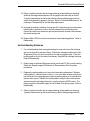
NovaJet® 8-Head Family
NovaJet
800 Series
Service Manual
®
NOVAJET®
800 Series
Color Inkjet Printer
Service Manual
Part Number 216520-01
NovaJet 800 Series Service Manual
Copyright Eastman Kodak Company, 2002
KODAK, ENCAD®, VinylJet®, VinylJet®, CADJET®,
Extreme Color Printing™, and Graphic Outdoor Matched
System™ (GO) are trademarks of Eastman Kodak
Company.
Other trademarks and registered trademarks are the
property of their respective owners.
No part of this manual may be copied or distributed,
transmitted, transcribed, stored in a retrieval system, or
translated in any human or computing language, in any
form or by any means, electronic, mechanical, magnetic
or otherwise, or disclosed to a third party without the
express written permission of:
Encad, Inc., 6059 Cornerstone Court West, San Diego,
CA 92121, U.S.A.
Certain manuals developed by ENCAD are in an electronic format to be distributed on CDs or over the
internet. The registered user of an ENCAD product
whose manual is distributed in this fashion may print one
copy for their personal use only.
Printing history
1st Edition
2nd Edition
Rev A
Rev B
December 2000
June 2002
iii
NovaJet 800 Series Service Manual
FCC Statement (U.S.A.)
The United States Federal Communications Commision
has specified that the following notice be brought to the
attention of the users of the NOVAJET 800 series printers.
FEDERAL COMMUNICATIONS COMMISION RADIO AND
TELEVISION INTERFERENCE FOR CLASS B DEVICE
This equipment has been tested and found to comply with
the limits for a class A digital device, pursuant to part 15
of the FCC Rules. These limits are designed to provide
reasonable protection against harmful interference in a
residential installation. This equipment generates, uses,
and can radiate radio frequency energy and, if not installed and used in accordance with the instructions, may
cause harmful interference to radio communications.
iv
NovaJet 800 Series Service Manual
User Instructions:
If the equipment does cause harmful interference to radio
or television reception, which can be determined by
turning the equipment off and on, the user is encouraged
to try to correct the interference by one of the following
measures:
−
Reorient or relocate the receiving antenna.
−
Increase the separation between the equipment and
receiver.
−
Connect the equipment into an outlet on a circuit
different from that to which the receiver is connected.
−
Consult the dealer or an experienced radio/TV
technician for help.
Changes or modifications not expressly approved by
ENCAD, Inc. could void the user’s authority to operate the
equipment.
v
NovaJet 800 Series Service Manual
VDE Statement
Hiermit wird bescheinigt, daß die NOVAJET 800 Serie
von Drucker in Übereinstimmung mit den Bestimmungen
der BMPT-AmstbIVfg 234/1991 funkentstört ist. Der
vorschriftsmäßige Betrieb mancher Geräte (z.B.
Meßsender) kann allerdings gewissen Einschränkungen
unterliegen. Beachten Sie deshalb die Hinweise in der
Bedienungsanleitung.
Dem Zentralamt für Zulassungen im Fernmeldewesen
würde dan Inverkehrbringen dieses Gerätes angezeigt und
die Berechtigung zur Überprüfung der Serie auf die
Einhaltung der Bestimmungen eingeräumt.
ENCAD, Inc. U.S.A
vi
NovaJet 800 Series Service Manual
Material Safety Data Sheet
ENCAD QIS (Quality Imaging Supplies) ink is nonhazardous, requiring no special disposal handling. It can be
harmful if swallowed and should be kept away from
children.
To obtain a Material Safety Data Sheet, contact ENCAD,
Inc. at:
6059 Cornerstone Court West
San Diego, CA 92121-3734
(619) 452-4350
International users should contact their local dealer or
distributor.
vii
NovaJet 800 Series Service Manual
Warranty or Damage Claims
United States
ENCAD®, Inc., warrants its printers ("PRODUCT") to be free from defects in
workmanship and materials for a period of one year from the date of
purchase. In order to submit a Warranty claim, please contact the
ENCAD Help Desk at (858) 452-4350.
ENCAD reserves the right to make changes or improvements to Products,
without incurring any obligation to similarly alter Products previously
purchased.
Buyer's sole and exclusive rights pursuant to this Warranty shall be for the
repair or replacement of defective Product. ENCAD specifically disclaims
any and all other warranties, expressed or implied, including but not limited
to, implied warranties of merchantability and fitness for a particular purpose. In no event shall ENCAD be liable for any loss of profit or other
commercial damages, special, incidental or consequential damages, or
any other damages or claims, whatsoever.
This Warranty gives Buyer specific legal rights, and Buyer may also have
other rights that vary from state to state.
This Warranty applies only to printers purchased from ENCAD, or authorized ENCAD distributors or dealers. The intent of this Warranty is to
repair or replace defective Products subjected to normal wear and tear,
when operated according to ENCAD instructions.
viii
NovaJet 800 Series Service Manual
Table of Contents
Chapter 1 General Description .......................................1-1
Introduction .................................................................................. 1-1
Overview ....................................................................................... 1-3
Related Publications ..................................................................... 1-3
Electrostatic Discharge (ESD) Sensitivity ...................................... 1-3
Warnings, Cautions and Notes ...................................................... 1-4
Printer Specifications .................................................................... 1-5
Contents of this Service Manual .................................................... 1-6
Technical Support ......................................................................... 1-8
Chapter 2 Theory of Operation .......................................2-1
Introduction .................................................................................. 2-1
NovaJet 800 Series Printers General Block Diagram ...................... 2-2
Paper (Media) Axis Drive ............................................................... 2-4
The Carriage Axis Drive ................................................................. 2-5
Media Feed and Take-Up System .................................................. 2-6
Main PWA (Printed Wiring Assembly) ........................................... 2-7
Main PWA LED Status Indicators ............................................ 2-8
Microprocessor (CPU) ............................................................ 2-8
Gate Array ............................................................................. 2-9
Digital Signal Processor (DSP) ............................................... 2-9
Memory Circuits ................................................................... 2-10
Flash EEPROM ............................................................. 2-10
SDRAM ......................................................................... 2-11
Serial EEPROM ............................................................. 2-11
Stepper Motor Controller ....................................................... 2-11
Servo Motor Controller .......................................................... 2-13
Interface Circuits: Serial & Parallel ........................................ 2-15
ix
NovaJet 800 Series Service Manual
Table of Contents (cont)
Chapter 3 Maintenance ...................................................3-1
Introduction .................................................................................. 3-1
Scheduled Maintenance ................................................................ 3-1
Cleaning Procedures .............................................................. 3-2
External Cleaning ............................................................. 3-2
Slide Shaft Cleaning ......................................................... 3-2
Service Station Cleaning ................................................... 3-3
Linear Encoder Strip Cleaning ........................................... 3-4
Trailing Cables Cleaning ................................................... 3-5
Platen/Vacuum Hole Cleaning ........................................... 3-5
Cartridge Dimples Cleaning .............................................. 3-6
Flex Cable Contact Cleaning ............................................ 3-7
Clean and Inspect Stepper Motor Gears ............................ 3-8
Clean and Inspect Main PWA ........................................... 3-8
Clean and Inspect Carriage Assembly ............................... 3-8
Dryer Cleaning ................................................................. 3-9
Reseat Connectors on Main PWA and Carriage Boards ........... 3-9
Replace Trailing Cables ........................................................ 3-12
Replace Carriage Cover/Carriage Bushings ............................ 3-13
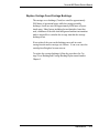
Servo Motor Winding Resistance Check ...................................... 3-14
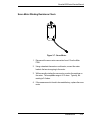
Stepper Motor Winding Resistance Check ................................... 3-15
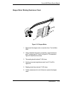
Power Feed and Take-Up Motor Winding Resistance Check ......... 3-16
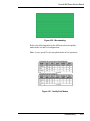
Banding: Hardware vs Software ................................................... 3-16
Banding Differences .............................................................. 3-17
Banding Causes & Quick Analysis ........................................ 3-19
Horizontal Banding Problems.......................................... 3-19
Vertical Banding Problems.............................................. 3-22
Line Quality Problems (Overspray) .................................. 3-23
Alignments/Adjustments ............................................................. 3-24
Slide Shaft Profile Adjustment ............................................... 3-24
Head Height Alignment Procedure ......................................... 3-27
Color Calibration ................................................................... 3-31
Deadband Alignments ........................................................... 3-34
Color Deadband Alignment .............................................. 3-37
Paper Axis Calibration .......................................................... 3-39
Diagnostics Menu ....................................................................... 3-40
Firmware Download/Upgrading for the PC .................................... 3-43
Firmware Download/Upgrading for the MAC ................................. 3-44
Internal Cabling and Signal Flow Diagrams .................................. 3-45
x
NovaJet 800 Series Service Manual
Table of Contents (cont)
Chapter 4 Troubleshooting .............................................4-1
Introduction .................................................................................. 4-1
No Power ............................................................................... 4-1
No Power ............................................................................... 4-2
Initialization Failure ................................................................. 4-2
Media Does Not Move............................................................. 4-3
Internal ERROR “Carriage Axis Failure” ................................... 4-4
Internal ERROR “Encoder Sensor Failure” ............................... 4-5
Internal ERROR “Paper Sensor Failure” ................................... 4-6
Internal ERROR ...................................................................... 4-6
Auto-Load Paper Sensor Failure” ............................................ 4-6
Internal ERROR “MPCB Failure” ............................................. 4-7
Unrecognized Cartridges Error ................................................ 4-7
Media Sen Ref. Pts Not Initialized (NJ880 only) ....................... 4-8
Image Skews or Moves ........................................................... 4-8
Does Not Print ....................................................................... 4-8
Ink Cartridge Misfiring ............................................................. 4-9
Paper Skewing ..................................................................... 4-10
Printer Output is Banding (Horizontal) ................................... 4-10
Printer Output is Banding (Vertical) ....................................... 4-12
Printer Output is Banding (Horizontally and Vertically) ........... 4-12
Keypad Locked-Up or Not Functioning Properly ..................... 4-13
Noisy Operation ................................................................... 4-13
Line Quality Degraded .......................................................... 4-14
Fan Does Not Power Up ....................................................... 4-16
Media Take-UpMotor Not Operating, Sensor Works ............... 4-16
Media Feed Motor Not Operating, Sensor Works ................... 4-17
Media Feed and Take-Up Motors Not Operating,
Both Sensors Working .......................................................... 4-17
Media Feed or Take-Up Sensor(s) Not Operating ................... 4-17
Print Quality Issues .............................................................. 4-19
Cartridge Misfires (Intermittent Banding) ................................ 4-19
Failure Analysis - Print Misfires ............................................ 4-20
Common Misfire Problems.............................................. 4-25
Clearing Cartridge Misfires .............................................. 4-26
Multiple Cartridge Failures .............................................. 4-26
xi
NovaJet 800 Series Service Manual
Table of Contents (cont)
Chapter 4 Troubleshooting (cont)
Microbanding ............................................................. 4-28
Banding Differences ................................................... 4-30
Horizontal Banding .................................................... 4-31
Vertical Banding ........................................................ 4-43
Line Quality Problems (Overspray) ............................. 4-46
Cartridge Warranty .................................................... 4-47
Cartridge Maintenance & Testing ................................ 4-48
Ink Starvation ............................................................. 4-52
Ink Dropout ............................................................... 4-57
Color Test Problems .................................................. 4-60
“Unrecognized Cartridge” Error Message .................... 4-63
Paper Sensor Error .................................................... 4-65
Encoder Sensor Error ................................................ 4-68
AutoLoad Paper Sensor Error .................................... 4-69
Carriage Axis Error .................................................... 4-70
Initialization Failure ................................................ 4-75
Media Sensor Reference Points Not Initialized ........... 4-79
Hardware Failures/Diagnostic Tests............................ 4-79
Dryer Failure/Sensor Error ......................................... 4-81
Intermittent Problems/Continuity ................................ 4-86
Reinitializing the Printer ............................................. 4-95
Printer Hesitation/Networking Problems...................... 4-96
Parallel Port Test ..................................................... 4-100
Firmware Downloading Procedures........................... 4-101
NJ850 Printer .......................................................... 4-101
NJ880 Printer .......................................................... 4-102
Media Handling System Failure................................ 4-104
xii
NovaJet 800 Series Service Manual
Table of Contents (cont)
Chapter 5 Assembly\Disassembly ................................5-1
Introduction .................................................................................. 5-1
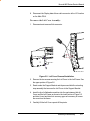
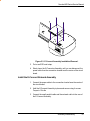
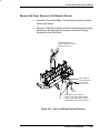
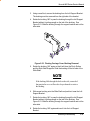
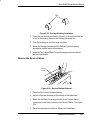
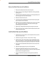
Remove the Left, Top, and Right Covers ......................................... 5-2
Remove the E-Connect Network Assembly .................................... 5-6
Install the E-Connect Network Assembly ....................................... 5-7
Remove the Keypad and Display ................................................... 5-8
Install the Keypad and Display ...................................................... 5-9
Remove Memory Module ............................................................. 5-10
Install Memory Module ................................................................ 5-11
Remove the Main Printed Wiring Assembly (PWA) ...................... 5-11
Install the Main Printed Wiring Assembly (PWA) ......................... 5-14
Remove Power Supply, Cooling Fan, and AC Entry Module .......... 5-15
Install the Power Supply, Cooling Fan, and AC Entry Module........ 5-17
Remove Servo Motor ................................................................... 5-18
Install Servo Motor ...................................................................... 5-20
Remove the Ink Delivery System ................................................. 5-21
Install the Ink Delivery System .................................................... 5-23
Remove the Carriage Assembly, Carriage Belt, and the Frame
Tensioner .................................................................................... 5-23
Install the Carriage Assembly, Carriage Belt, and the
Frame Tensioner ......................................................................... 5-28
Remove the Carriage PWA.......................................................... 5-31
Install the Carriage PWA............................................................. 5-33
Remove the Paper Sensor or the Encoder Sensor ........................ 5-34
Install the Paper Sensor or the Encoder Sensor ........................... 5-36
Replacing the Floating Carriage Cover Bushings .......................... 5-37
Replacing the Carriage Bushings ................................................. 5-39
Remove the Service Station ......................................................... 5-40
Install the Service Station ............................................................ 5-41
Remove the Trailing Cable Assembly ........................................... 5-41
Install the Trailing Cable Assembly .............................................. 5-42
Remove the Stabilizer Bracket and Encoder Strip ......................... 5-43
Install the Stabilizer Bracket and Encoder Strip ............................ 5-44
Remove the Y-Arm Assembly, Pinch Rollers, Slide Shaft, and
AutoLoad Sensor ........................................................................ 5-44
Install the Y-Arm Assembly, Pinch Rollers, Slide Shaft,
and AutoLoad Sensor .................................................................. 5-47
Remove the Gap Sensor (NovaJet 880 only) ................................. 5-48
xiii
NovaJet 800 Series Service Manual
Table of Contents (cont)
Chapter 5 Assembly\Disassembly (cont)
Remove the Lower Roller Assembly, Stepper Motor and
Vacuum Fan (NovaJet 850) .......................................................... 5-48
Install the Lower Roller Assembly, Stepper Motor and
Vacuum Fan (NovaJet 850) .......................................................... 5-51
Remove the Lower Roller Assembly, Stepper Motor and
Vacuum Fan (NovaJet 880) .......................................................... 5-54
Lower Roller Installation Tip (NovaJet 880) ................................... 5-57
Y-Arm Assembly Installation Tip (NovaJet 880) ............................. 5-57
Remove the Media Take-Up and Feed Sensor Brackets and
Sensors ..................................................................................... 5-58
Install the Media Take-Up and Feed Sensor Brackets and
Sensors ..................................................................................... 5-59
Remove the Media Take-Up and Feed Motors .............................. 5-60
Install the Media Take-Up and Feed Motors ................................. 5-60
Remove the Thermal Dryer Assembly .......................................... 5-61
Install the Thermal Dryer Assembly ............................................. 5-62
Remove the Thermal Dryer Right Endcap Assembly ..................... 5-62
Install the Thermal Dryer Right Endcap Assembly ............................ 564Assembly\Disassembly............................................................. 5-1
Introduction .................................................................................. 5-1
Remove the Left, Top, and Right Covers ......................................... 5-2
Remove the E-Connect Network Assembly .................................... 5-6
Install the E-Connect Network Assembly ....................................... 5-7
Remove the Keypad and Display ................................................... 5-8
Install the Keypad and Display ...................................................... 5-9
Remove Memory Module ............................................................. 5-10
Install Memory Module ................................................................ 5-11
Remove the Main Printed Wiring Assembly (PWA) ...................... 5-11
Install the Main Printed Wiring Assembly (PWA) ......................... 5-14
Remove Power Supply, Cooling Fan, and AC Entry Module .......... 5-15
Install the Power Supply, Cooling Fan, and AC Entry Module........ 5-17
Remove Servo Motor ................................................................... 5-18
Install Servo Motor ...................................................................... 5-20
Remove the Ink Delivery System ................................................. 5-21
Install the Ink Delivery System .................................................... 5-23
xiv
NovaJet 800 Series Service Manual
Table of Contents (cont)
Chapter 5 Assembly\Disassembly (cont)
Remove the Carriage Assembly, Carriage Belt, and the Frame
Tensioner .................................................................................... 5-23
Install the Carriage Assembly, Carriage Belt, and the
Frame Tensioner ......................................................................... 5-28
Remove the Carriage PWA.......................................................... 5-31
Install the Carriage PWA............................................................. 5-33
Remove the Paper Sensor or the Encoder Sensor ........................ 5-34
Install the Paper Sensor or the Encoder Sensor ........................... 5-36
Replacing the Floating Carriage Cover Bushings .......................... 5-37
Replacing the Carriage Bushings ................................................. 5-39
Remove the Service Station ......................................................... 5-40
Install the Service Station ............................................................ 5-41
Remove the Trailing Cable Assembly ........................................... 5-41
Install the Trailing Cable Assembly .............................................. 5-42
Remove the Stabilizer Bracket and Encoder Strip ......................... 5-43
Install the Stabilizer Bracket and Encoder Strip ............................ 5-44
Remove the Y-Arm Assembly, Pinch Rollers, Slide Shaft, and
AutoLoad Sensor ........................................................................ 5-44
Install the Y-Arm Assembly, Pinch Rollers, Slide Shaft, and
AutoLoad Sensor ........................................................................ 5-47
Remove the Gap Sensor (NovaJet 880 only) ................................. 5-48
Remove the Lower Roller Assembly, Stepper Motor and
Vacuum Fan (NovaJet 850) .......................................................... 5-48
Install the Lower Roller Assembly, Stepper Motor and Vacuum
Fan (NovaJet 850) ....................................................................... 5-51
Remove the Lower Roller Assembly, Stepper Motor and
Vacuum Fan (NovaJet 880) .......................................................... 5-54
Lower Roller Installation Tip (NovaJet 880) ................................... 5-57
Y-Arm Assembly Installation Tip (NovaJet 880) ............................. 5-57
Remove the Media Take-Up and Feed Sensor Brackets and
Sensors ..................................................................................... 5-58
Install the Media Take-Up and Feed Sensor Brackets and
Sensors ..................................................................................... 5-59
Remove the Media Take-Up and Feed Motors .............................. 5-60
Install the Media Take-Up and Feed Motors ................................. 5-60
Remove the Thermal Dryer Assembly .......................................... 5-61
Install the Thermal Dryer Assembly ............................................. 5-62
Remove the Thermal Dryer Right Endcap Assembly ..................... 5-62
Install the Thermal Dryer Right Endcap Assembly ........................ 5-64
xv
NovaJet 800 Series Service Manual
Table of Contents (cont)
Chapter 6 Parts List ........................................................6-1
xvi
NovaJet 800 Series Service Manual
List of Illustrations
Figure
Page
Chapter 1 General Description
1-1. NovaJet 800 Series Inkjet Printer ................................................. 1-1
Chapter 2 Theory of Operation
2-1. General Block Diagram. .............................................................. 2-3
2-2. Paper (Media) Axis Drive. ............................................................ 2-4
2-3. Carriage Axis Drive. ..................................................................... 2-5
2-4. Power Feed and Take-Up System. ............................................... 2-6
2-5. Main PWA (Printed Wiring Assembly). ......................................... 2-7
2-6. Gate Array. ................................................................................. 2-9
2-7. Stepper Motor Controller. ........................................................... 2-11
2-8. Servo Motor Controller. .............................................................. 2-13
2-9. Quadrature Signal Generation. ................................................... 2-14
2-10. Interface Circuits. .................................................................... 2-15
2-11. Carriage Assembly Circuits. ..................................................... 2-16
2-12. Main Menu. ............................................................................. 2-18
Chapter 3 Maintenance
3-1. Encoder Strip Cleaning. ............................................................... 3-4
3-2. Cartridge Dimple Region. ............................................................. 3-6
3-3. Flex Cable Contacts. ................................................................... 3-7
3-4. Main PWA Connection Locations. .............................................. 3-10
3-5. Carriage PWA Connection Locations. ........................................ 3-11
3-6. Ribbon Connector Locking Mechanism. ..................................... 3-12
3-7. Servo Motor. .............................................................................. 3-14
3-8. Stepper Motor. .......................................................................... 3-15
3-9. Power Feed and Take-Up Motor. ................................................ 3-16
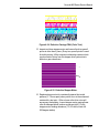
3-10. Examples of Horizontal Banding. ............................................. 3-17
3-11. Dial Gauge Micrometer Assembly. ........................................... 3-25
3-12. Measurement Positions for Slide Shaft. .................................... 3-26
3-13. Slide Shaft Profile Adjustment. ................................................. 3-27
3-14. Carriage Head Height Tolerance. .............................................. 3-28
3-15. Setting Up Tools from Height Gauge Kit. ................................. 3-28
3-16. Zeroing the Micrometer Gauge. ................................................ 3-29
3-17. Test Cartridge Installed. ........................................................... 3-29
3-18. Vert. and Horiz. Color Calibration. ............................................ 3-32
3-19. Utility Menu. ........................................................................... 3-33
xvii
NovaJet 800 Series Service Manual
List of Illustrations (cont)
Figure
Page
Chapter 3 Maintenance (cont.)
3-20.
3-21.
3-22.
3-23.
3-24.
3-25.
3-26.
3-27.
3-28.
3-29.
3-31.
3-32.
Color Calib Menu. .................................................................... 3-33
Vertical Options Menu. ............................................................ 3-34
Slow Deadband. ...................................................................... 3-35
Service Menu. ......................................................................... 3-36
Calibration (Deadband) Menu. .................................................. 3-36
Calibration Menu. .................................................................... 3-37
Color Db Menu. ....................................................................... 3-38
Paper Axis Test. ...................................................................... 3-40
Diagnostics Menu. .................................................................. 3-41
Accessory Menu. .................................................................... 3-41
Carriage PWA Connections Diagram. ....................................... 3-46
Leg Harness Connections Diagram. ......................................... 3-47
Chapter 4 Troubleshooting
4-1. Cartridge Misfire. ..................................................................... 4-19
4-2. Excessive Ink Pressure. .......................................................... 4-20
4-3. Dirty Service Station. ............................................................... 4-21
4-4. Septum and Valves. ................................................................. 4-21
4-5. Unseated Flex Driver Cable. ..................................................... 4-22
4-6. Septum Connector. .................................................................. 4-22
4-7. Damaged Flex Driver Cable. ..................................................... 4-23
4-8. Defective Trailing Cable. ........................................................... 4-23
4-9. Unseated or Defective Trailing Cable. ........................................ 4-24
4-10. Defective Carriage PWA. ......................................................... 4-24
4-11. Stall Configuration. ................................................................... 4-25
4-12. Magenta Cartridge Misfires. ..................................................... 4-25
4-13. Adjacent Jet Misfire (Cyan). ..................................................... 4-26
4-14. Service Station. ....................................................................... 4-27
4-15. Defective Cartridge Power Lines. .............................................. 4-27
4-16. Catastrophic Jet Failure. ........................................................... 4-28
4-17. Power Line Failure. .................................................................. 4-28
4-18. Address Line Failure. ............................................................... 4-28
4-19. Multiple Address Line Failure. .................................................. 4-28
4-20. Microbanding. .......................................................................... 4-29
4-21. Quality Print Modes. ................................................................ 4-29
4-22. Ink Cartridge Configurations. .................................................... 4-30
4-23. Defective Magenta Cartridge. .................................................... 4-31
4-24. AutoWipe Interference. ............................................................ 4-32
4-25. Improper Grounding. ................................................................ 4-32
xviii
NovaJet 800 Series Service Manual
List of Illustrations (cont)
Figure
Page
Chapter 4 Troubleshooting (cont)
4-26. Unseated or Defective Trailing Cables. ...................................... 4-33
4-27. ESD Problems. ........................................................................ 4-34
4-28. Defective Carriage PWAs. ........................................................ 4-34
4-29. Carriage Head Strike. ............................................................... 4-35
4-31. Low Data Transfer Problem. ..................................................... 4-35
4-32. Test Print. ................................................................................ 4-36
4-33. Misfiring Jet. ............................................................................. 4-36
4-34. Defective Carriage PWA (Color Test). ........................................ 4-37
4-35. Defective Stepper Motor. ........................................................... 4-37
4-36. Defective Stepper Motor. ........................................................... 4-38
4-37. Servo System Synchronization Failure. ..................................... 4-39
4-38. RIP Error. ................................................................................. 4-39
4-39. Connectivity Problem . .............................................................. 4-40
4-40. Dirty or Defective Encoder Strip. ............................................... 4-40
4-41. Main PWA Failures. ................................................................. 4-41
4-42. RIP Problem. ........................................................................... 4-42
4-4. Bent Servo Motor Pulley. .......................................................... 4-42
4-44. Dirty or Worn Carriage Bushings. ............................................. 4-43
4-45. Worn Bushings or Bushing Pads. ............................................ 4-43
4-46. Defective Trailing Cable Examples. ........................................... 4-44
4-47. Dirty Encoder Strip. ................................................................. 4-45
4-48. Defective Teflon Strip. .............................................................. 4-45
4-49. RIP Error (Page Layout Violation). ............................................ 4-46
4-50. ESD Problem. ......................................................................... 4-47
4-51. Jet Out Detection. ................................................................... 4-48
4-52. Cartridge Cleaning. .................................................................. 4-50
4-53. Service Station Cleaning. ......................................................... 4-51
4-54. Magenta Ink Pressure Failure. ................................................. 4-52
4-55. Ghosting. ................................................................................ 4-53
4-56. Cartridge Tubing Needle and Septum. ...................................... 4-54
4-57. 208 Jet Cartridge. .................................................................... 4-55
4-58. EasyPrime Operation. ............................................................. 4-55
4-59. Reservoirs and Ink Delivery System.......................................... 4-56
4-60. Excessive Ink Pressure. .......................................................... 4-57
4-61. Excessive Ink PreHeat Settings. .............................................. 4-58
4-62. Dirty Service Station Problem. .................................................. 4-60
xix
NovaJet 800 Series Service Manual
List of Illustrations (cont)
Figure
Page
Chapter 4 Troubleshooting (cont)
4-63.
4-64.
4-65.
4-66.
4-67.
4-68.
4-69.
4-70.
4-71.
4-72.
4-73.
4-74.
4-75.
4-76.
4-77.
4-78.
4-79.
4-80.
4-81.
4-82.
4-83.
4-84.
4-85.
4-86.
4-87.
4-88.
4-89.
4-90.
4-91.
4-92.
4-93.
4-94.
4-95.
4-96.
4-97.
Normal Color Test (3 Pass). ..................................................... 4-61
Abnormal Test Examples. ........................................................ 4-61
Cartridge Tubing Needle and Septum. ...................................... 4-62
Ink Starvation. ......................................................................... 4-63
Cartridge Identification Chip. .................................................... 4-64
Flex Driver Cable. .................................................................... 4-65
Paper Sensor. ......................................................................... 4-66
Paper Sensor Location. ........................................................... 4-68
Encoder Sensor. ..................................................................... 4-68
AutoLoad Paper Sensor. .......................................................... 4-70
Carriage Head Assembly. ......................................................... 4-71
Servo Cycle/PWM Menu. ......................................................... 4-71
Dirty or Defective Encoder Strip. ............................................... 4-72
Main PWA Trailing Cable Connection. ...................................... 4-74
Boot ROM Access Function. ................................................... 4-75
Main PWA LED Operation. ...................................................... 4-76
Memory Module. ..................................................................... 4-76
Paper Sensor. ......................................................................... 4-78
Main PWA LED Operation. ...................................................... 4-79
Functional Problem................................................................. 4-80
Connectivity Problem. .............................................................. 4-80
ESD Problem. ......................................................................... 4-81
Main PWA Humidity Sensor. .................................................... 4-82
Dryer LEDs. ............................................................................ 4-85
Dryer Connectivity. .................................................................. 4-85
Internal Test Print. ................................................................... 4-86
SEH Activated Test Pattern. ..................................................... 4-87
E-Connect LEDs. .................................................................... 4-87
Driver/RIP Problem. ................................................................. 4-88
Inadaquate Network Data Transfer Rate. .................................. 4-88
ESD Problems. ....................................................................... 4-89
Servo Cycle/PWM Menu. ........................................................ 4-90
Carriage Bushings. ................................................................. 4-90
Servo System Synchronization Error. ...................................... 4-91
Probable Defective Main PWA. ............................................... 4-91
xx
NovaJet 800 Series Service Manual
List of Illustrations (cont)
Figure
Page
Chapter 4 Troubleshooting (cont)
4-98. Probable Defective Carriage PWA. .......................................... 4-92
4-99. Defective Main PWA. ............................................................. 4-92
4-100. Corrupted Code - Main PWA. .................................................. 4-93
4-101. Microbanding. ......................................................................... 4-93
4-102. Apparent Ink Overspray. ......................................................... 4-94
4-103. True Type Font Problem. ......................................................... 4-94
4-104. Print Settings Not Printing in Black. ........................................ 4-94
4-105. Text Field Problem. ................................................................ 4-95
4-106. Dirty or Defective Encoder Strip. .............................................. 4-95
4-107. Initialization Menu Location. .................................................... 4-96
4-108. Printer Hesitation Causes. ...................................................... 4-97
4-109. E-Connect LEDs. ................................................................... 4-99
4-110. Semi-Circular Nook Test Pattern. ............................................ 4-99
4-111. Loopback Test Cable. ........................................................... 4-100
4-112. Demo Print. ......................................................................... 4-101
4-113. Firmware Download Procedures. .......................................... 4-102
4-114. Media Handling System. ...................................................... 4-104
Chapter 5 Assembly/Disassembly
5-1.
5-2.
5-3.
5-4.
5-5.
5-6.
5-7.
5-8.
5-9.
5-10.
5-11.
5-12.
5-13.
5-14.
5-15.
5-16.
5-17.
Right Cover Assembly Removal/Installation. .............................. 5-3
Left Cover Removal/Installation. ................................................ 5-4
E-Connect Assembly Installation/Removal. ............................... 5-7
Keypad and Display Installation/Removal. ................................. 5-8
Keypad and Display Grounding Connections. ............................ 5-9
Memory Module Removal/Installation. ..................................... 5-10
Main PWA Removal. .............................................................. 5-13
Power Supply Removal. .......................................................... 5-16
Cooling Fan/AC Entry Module Removal. .................................. 5-17
Using the Belt Removal Tool. .................................................. 5-19
Chain Guide Removal. ............................................................ 5-21
Left Side of Ink Delivery System. ............................................ 5-22
Floating Carriage Cover Removal. ........................................... 5-22
Using the Belt Removal Tool. .................................................. 5-24
Electronics Covers Removal. .................................................. 5-25
Strain Relief Removal/Installation. ............................................ 5-26
Carriage Belt Clamp. ............................................................... 5-27
xxi
NovaJet 800 Series Service Manual
List of Illustrations (cont)
Figure
Page
Chapter 5 Assembly/Disassembly (cont.)
5-18.
5-19.
5-20.
5-21.
5-22.
5-23.
5-24.
5-25.
5-26.
5-27.
5-28.
5-29.
5-30.
5-31.
5-32.
5-33.
5-35.
5-36.
Carriage Coupler Installation. ................................................... 5-28
Left Carriage Installation. ......................................................... 5-29
Carriage PWA Removal/Installation. ......................................... 5-32
Paper and Encoder Sensor Removal. ....................................... 5-34
Paper and Encoder Sensor Installation. .................................... 5-36
Floating Carriage Cover Bushing Removal. ............................... 5-38
Carriage Bushing Removal. ...................................................... 5-39
Carriage Bushing Installation. .................................................. 5-40
Service Station Removal. ......................................................... 5-40
Stabilizer Bracket Installation/Removal. .................................... 5-43
Y-Arm Installation/Removal. ..................................................... 5-45
Pinch Roller. ........................................................................... 5-46
Stepper Motor Removal/Installation. ......................................... 5-51
Inside Platen, Right Side. ........................................................ 5-53
Media Take-Up and Feed Sensor Removal. .............................. 5-59
Media Take-Up and Feed Motor Removal. ................................. 5-61
Dryer Right Endcap Removal/Installation. ................................. 5-63
Right Endcap Connector Locations. ......................................... 5-65
Chapter 6 Parts List
6-1.
6-2.
6-3.
6-4.
6-5.
6-6.
6-7.
6-8.
Left Side Parts Breakdown. ......................................................... 6-3
Platen and Above Parts Breakdown. ............................................ 6-5
Right Side Parts Breakdown. ....................................................... 6-7
Inner Platen Parts Breakdown. .................................................... 6-9
Carriage Assembly Parts Breakdown. ........................................ 6-11
Floating Carriage Cover Parts Breakdown. .................................. 6-13
Service Station Parts Breakdown. .............................................. 6-15
Power Feed and Take-Up Parts Breakdown. ............................... 6-17
xxii
NovaJet 800 Series Service Manual
List of Tables
Table
Page
Chapter 3 Maintenance
3-1. Main PWA Connections. ............................................................ 3-10
3-2. Carriage PWA Connections. ....................................................... 3-11
Chapter 4 Troubleshooting
4-1. Troubleshooting Table. ................................................................. 4-1
Chapter 5 Assembly/Disassembly
5-1. Thermal Dryer PWA Connections. ............................................... 5-65
xxiii
NovaJet 800 Series Service Manual
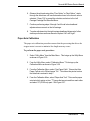
General Description
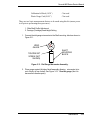
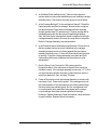
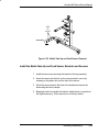
1
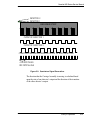
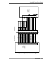
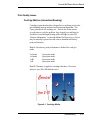
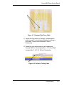
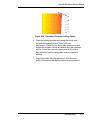
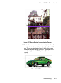
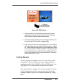
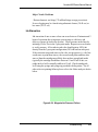
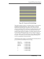
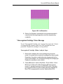
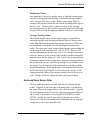
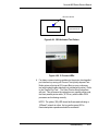
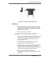
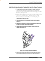
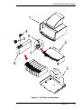
Figure 1-1. NovaJet 800 Series Inkjet Printer.
Introduction
This manual provides service information for the ENCAD®, Inc.
NovaJet® 800 Series Color Inkjet Printers. The NovaJet 850
printer is available in two sizes: a 42 inch model and a 60 inch model.
The NovaJet 880 printer is available in a 60 inch model.
It is written for service personnel who possess analog and digital
circuitry experience. Chapter 2, Theory of Operation, should be read
and thoroughly understood before troubleshooting/calibrating the
printers.
The printers support pre-cut and roll media. Media size is automatically
determined and hardclip limits are set accordingly. Pre-cut media uses
different maximum plotting areas than roll media. See the Printer
Specifications in the User Reference Guide for more details on the
media size printable area.
General Description
1-1
NovaJet 800 Series Service Manual
A Centronics parallel connection is provided to interface with the host computer.
Commands sent from the host computer can be in several forms including HP-GL/2,
HP-RTL and Encad RTL formats.
Drivers are supplied to support Windows®-based PCs (95, 98, ME, NT and 2000) as
well as Macintosh and Power PC computers.
These printers expand upon ENCAD’s tradition of delivering fast, high-quality color or
monochrome graphics for a variety of applications. ENCAD has made significant
advances in designing these printers to respond to and anticipate our customers’ needs.
Principal features are summarized below.
Locally or Remotely Configured via Host Computer
Powered Media Handling System
Dynamic Thermal Drying System
V8 12-Ink Line Delivery System
Quick Ink Changeover
Anti-Skew Pinch Rollers
PowerPC 50 MHz Microprocessor
8 User Configurable Settings
208 Jet Ink Cartridges
Ink Priming System
500ml Ink Reservoirs
Smart Cartridges
Media Tracking Function
10/100BaseT Network Interface
Rigid Media Handling System (NJ880 only)
General Description
1-2
NovaJet 800 Series Service Manual
Overview
Printers draw according to instructions issued from a “host” computer.
Every printer is engineered to understand a specific set of instructions
and to execute each instruction in a precise manner. In addition, most
printers are designed to execute predetermined characters automatically
without a specific line-by-line instruction from the program. These
characters are part of the printer’s permanent memory.
Related Publications
The following publication contains additional information which may be
useful in servicing the NovaJet 800 Series Color Inkjet Printers:
?
?
ENCAD NovaJet 800 Series Quick Start Guide,
P/N 215360-XX
ENCAD NovaJet 800 Series System CD-ROM,
P/N 215363-XX
Copies of these and other ENCAD, Inc. publications may be obtained
by contacting your nearest authorized ENCAD, Inc. dealer or by
contacting ENCAD’s Technical Support and Service Department.
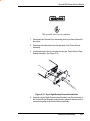
Electrostatic Discharge (ESD) Sensitivity
All PCBs (Printed Circuit Boards) associated with these printers have
components sensitive to ESD (electrostatic discharge). Care must be
taken to avoid damage to any of the components by following current
ESD handling procedures and practices.
Always use an approved ESD grounding strap when handling or working
with PCBs.
General Description
1-3
NovaJet 800 Series Service Manual
Warnings, Cautions and Notes
Warnings, cautions and notes are used when additional information,
instructions or care should be observed. In this manual warnings,
cautions and notes precede the text to which each applies. The
definition of each is provided below.
WARNINGS - Warnings are used to stress that the following steps or
procedures has the potential to cause serious harm or death to service
personnel. Extreme care should be observed when following the
procedures and to exercise standard safety procedures. They are
indicated by:
Followed by a paragraph describing the concern.
CAUTION - Cautions depict that the following steps or procedures
can cause damage to the equipment if not properly followed. Extreme
care should be observed when following the procedures and to exercise
standard safety procedures. They are indicated by:
Followed by a paragraph describing the concern.
NOTE - Notes are placed before a procedure to inform the service
personnel of specific details to improve quality, to give reminders of
interrelated parts and to provide other helpful information. They are
indicated by:
NOTE
Followed by a paragraph describing the concern.
General Description
1-4
NovaJet 800 Series Service Manual
Printer Specifications
The specifications and performance characteristics of the NovaJet
800 Series Color Inkjet Printers are as follows:
Max Printing Area:
42 inch 60 inch
Norm
40.8”
58.8”
1.04m
1.49m
Extend 41.61” 59.61”
1.06m
1.51m
Language Emulation:
HP-RTL
ENCAD RTL
HP GL/2
Buffer:
64 MB installed
upgradeable to 256 MB
Power Requirements:
Input Voltage:
90-246 VAC
47-63 Hz
Output Power:
20 W idle
185 W typical
285 W maximum
1485 W maximum (with
dryer on)
Resolution:
600x600 dpi or
300x300 dpi RTI
Accuracy:
+/- 0.2% line length using
ROLL feed and 4 mil
drafting matte film
Interface:
Centronics parallel
(IEEE 1284)
Network: via
100BaseT Interface
Certifications:
Safety
CSA, CSE/NRTL
(equivalent to UL1950)
TUV GS
EN 50 082-1
EN 60 950
UL1950
NOM-019-SCFI-1993
IEC 950
AS/NZS 3260
EMI
FCC Class A
CSA C108.8
EN 55 022 Class A
CE Mark
CISPR 22- Class A
AS/NZS 3548
General Description
1-5
NovaJet 800 Series Service Manual
Environment:
Operating:
65° to 85° F
(18° to 30° C)
5% to 80% RH
non-condensing
Storage:
40° to 95° F
(4° to 35° C)
5% to 80% RH
non-condensing
Weight: NJ850
60”
165 lbs
42”
150 lbs
Dimensions:
Height
44”(1.12m)
Width
48” (1.22m)
93” (2.37m)
42 inch
111” (2.82m)
60 inch
Depth
NJ880
235 lbs
111” (2.82m)
28” (0.71m)
Contents of this Service Manual
Figures are used in this manual to clarify procedures. They are for
illustrative purposes only and may not necessarily be drawn to scale.
Material in this manual may be repeated in various chapters so that
each chapter can “stand alone”. This allows information to be located
without having to refer back and forth between chapters.
Figures and tables are easily located and cross-referenced, and are
listed in the front of the manual under List of Illustrations and List of
Tables.
This manual is divided into six chapters as follows:
Chapter 1 GENERAL DESCRIPTION - Contains a general
description of the ENCAD NovaJet 800 Series printer. This
includes printer specifications, and related materials. Also
included is a description of the use of Warnings, Cautions
and Notes as used in this manual and chapter contents.
Chapter 2 THEORY OF OPERATION - Functional descriptions
of the overall printer and major assemblies are contained in
this chapter.
General Description
1-6
NovaJet 800 Series Service Manual
Chapter 3 MAINTENANCE - This chapter covers the scheduled maintenance,
cleaning procedures and alignment/adjustments recommended to perform on
the printers. Diagnostics and a signal flow diagram are also listed.
Chapter 4 TROUBLESHOOTING - A table containing problems that could occur
and possible causes and repairs is found in this chapter. This table is not
intended to be a complete listing of troubleshooting procedures. It will
isolate the problem down to the lowest replacable assembly. If the problem
happens to be the wiring between assemblies, standard troubleshooting
techniques will have to be implemented to correct the problem.
Chapter 5 ASSEMBLY/DISASSEMBLY - Contains detailed procedures to
remove and replace printer parts and assemblies.
Chapter 6 PARTS LIST - Contains a complete listing of all field replacable parts
and assemblies for the color inkjet printers. Illustrated parts breakdown
drawings are included to help clarify and identify parts for ordering. Special
kits and adjustment jigs may also be required.
ORIENTATION - Instructions in this manual are based on the assumption that the
service person is facing the front of the printer. References to top view, back view, and
so forth are consistent with this engineering standard. References to the X Axis and
Y Axis (Paper Axis and Carrier Axis, respectively) follow the standard of
AutoCAD™ absolute coordinates: up and down for X, left to right for Y.
General Description
1-7
NovaJet 800 Series Service Manual
Technical Support
ENCAD offers full technical support and service for its various products. If you are unable to find the answer to your question in either the
User’s Guide, Service Manual, or other related publications, check out
ENCAD’s Knowledge Base located on ENCAD’s website support:
ENCAD Website:
http://www.encad.com
Additional information is available though our Technical Support and
Service Department’s Help Desk.
ENCAD, Inc.
Technical Support & Service Dept.
6059 Cornerstone Court West
San Diego, CA 92121
Help Desk Telephone:
Help Desk FAX:
(858) 452-4350 or
(877) ENCAD-TS (362-2387)
(858) 558-4672
International users contact your local ENCAD service provider. See
details on your ENCAD registration card.
General Description
1-8
Theory of Operation
2
Introduction
This chapter explains the mechanical and electrical theory of operation
of the ENCAD NovaJet 800 Series Color Inkjet printers.
The NovaJet 800 Series V-8 print engine has eight ink cartridges,
eight 500-milliliter ink reservoirs and 12 independent ink lines. The
cartridges are housed in a torque-free floating carriage assembly that
eliminates micro banding by providing vibration-free printing. To ensure
that prints are dry for unattended printing, the printer has a dynamic
thermal drying system. The printer includes an optically controlled take
up and feed system as standard equipment. Printer hardware features
also include an easy-to-read LCD display. An integrated 100BaseT
network connection provides seamless network and workstation
communication. The printer power switch is located at the right rear
of the printer.
The NovaJet 800 Series is a PowerPC 48MHz microprocessorbased digital printer that receives plotting instructions from a host
computer through the Centronics parallel interface.
2-1
NovaJet 800 Series Service Manual
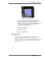
NovaJet 800 Series Printers General Block Diagram
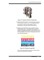
Figure 2-1 illustrates the major functional areas of the printers.
The NovaJet 800 Series printers consist of three mechanical assemblies:
1. Paper (Media) Axis Drive
2. Carriage Axis Drive
3. Media Feed and Take-Up System
and five main electrical assemblies:
1. Main PWA (Printed Wiring Assembly)
2. Carriage Assemblies (2)
3. Control Panel
4. Power Supply
5. Thermal Dryer Assembly
Theory of Operation
2-2
NovaJet 800 Series Service Manual
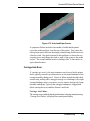
Figure 2-1. General Block Diagram.
Theory of Operation
2-3
NovaJet 800 Series Service Manual
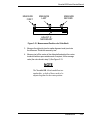
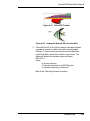
Paper (Media) Axis Drive
Figure 2-2. Paper (Media) Axis Drive.
The Paper (Media) Axis Drive moves the plotting media in a direction
perpendicular to the length of the printer. This friction drive utilizes a
micro-step drive technology and consists of a stepper motor, reduction
gears, lower drive shaft assembly, and pinch rollers. This can be seen in
Figure 2-2.
The micro-step technology associated with the stepper motor gives the
capability of a resolution up to 9600 dpi.
The reduction gear meshes the stepper motor to the lower drive shaft
assembly which allows the media to advance or retract. The purpose of
the pinch rollers is to apply pressure to the media onto the drive shaft
assembly to reduce the chance of slipping.
Misaligned pinch wheels is a main cause of skewing of the media. For
that reason the NovaJet 800 Series was designed with self aligning
pinch rollers. As the media is fed forward, the rollers are aligned correctly. However, these pinch rollers will not stay aligned while the media
is being fed backwards.
Theory of Operation
2-4
NovaJet 800 Series Service Manual
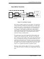
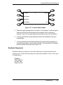
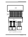
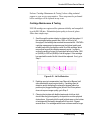
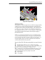
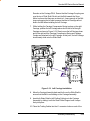
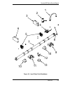
The Carriage Axis Drive
OPTICAL ENCODER
OPTICAL SENSOR
TRAILING
CABLE
PAPER SENSOR
TRAILING
CABLE
CONNECTION
FROM
MAIN
PWA
CARRIAGE
PWA
RIGHT CARRIAGE
ASSEMBLY ONLY
CARTRIDGE 1
INKJET
DRIVERS
CARTRIDGE 2
CARTRIDGE 3
CARTRIDGE 4
LEFT AND RIGHT CARRIAGE ASSEMBLY
Figure 2-3. Carriage Axis Drive.
The Carriage Axis Drive moves the printer’s carriage assembly along the
length of the printer. The drive consists of a servo motor, linear encoder
strip, drive belt, and tensioning assembly. These items are illustrated in
Figure 2-3.
The servo motor, drive belt, and tensioning assembly are the components
that actually drive the carriage assembly. The servo motor drives the belt
back and forth allowing the attached carriage assemblies to be repositioned as required. The tensioning assembly is spring controlled and
allows the proper amount of tension on the belt.
The linear optical encoder strip is used to obtain the printers accuracy
along the axis of the printer. The strip of film has 150 parallel lines per
inch printed on it. By utilizing two optical encoder sensors that are
slightly off set from each other, and reading the leading and trailing edges
of the lines, a resolution of 600 dpi can be obtained.
The stepper and servo motors are controlled from the main printed circuit
assembly by the microprocessor.
Theory of Operation
2-5
NovaJet 800 Series Service Manual
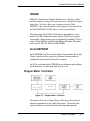
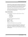
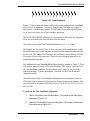
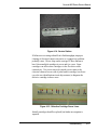
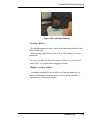
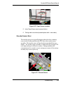
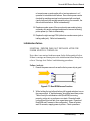
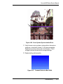
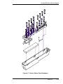
Media Feed and Take-Up System
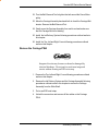
REFLECTOR
SENSORS
REFLECTOR
Figure 2-4. Power Feed and Take-Up System.
The media feed and take-up system comprises of two optical sensors,
two dc motors and a dryer assembly. See Figure 2-4.
Motors are used to advance the media feed roll and the media take-up
roll dependent upon the signals they receive from the Main PWA. The
Main PWA generates the control signals for the motors from the information it receives from the media feed and take-up sensors. The Main PWA
also controls the dryer assembly.
Theory of Operation
2-6
NovaJet 800 Series Service Manual
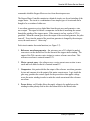
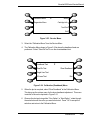
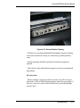
Main PWA (Printed Wiring Assembly)
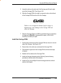
Figure 2-5. Main PWA (Printed Wiring Assembly).
The Main PWA (Printed Wiring Assembly) consists of seven functional
areas:
1.
Microprocessor (CPU)
2.
Gate Array
3.
Memory Circuits
4.
Stepper Motor Controller
5.
Servo Motor Controller
6.
Interface Circuits:
7.
Temperature and Humidity Control
Serial & Parallel
Theory of Operation
2-7
NovaJet 800 Series Service Manual
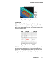
Main PWA LED Status Indicators
D1 - Normally flashes when the DSP is idle. Steady during print operations.
D8 - +24V available.
D9 - Normally flashes when the Power PC processor is idle. Stops
flashing when processor is busy (i.e. during paper sensing operations or
printing).
D10 - Normally OFF; Flashes during initialization, then turns off. LED
staying on would indicate a problem when the FPGA is unconfigured.
Ensures the gate array chips have been properly programmed (one on
Main PWA and on each Carriage PWA).
D13 - +5V available.
Microprocessor (CPU)
The microprocessor (a 48MHz PowerPC 860 from Motorola) is the
central processor unit which supervises system functions, executes the
printer firmware, manipulates data, and controls input/output data busses.
It has four built-in serial ports, a two channel DMA (Direct Memory
Access) controller, a timer module, clock generator, and an on-board chip
select generator. The serial ports are not used and are disabled in all
shipping firmware. One DMA channel is used to receive data through
the parallel port via the gate array. One timer generates a servo interrupt
every millisecond; another is used to coordinate firmware multi-tasking.
The chip select generator is programmed to generate chip selects at the
appropriate addresses, with the appropriate data size (byte, word) and
with the appropriate number of wait states.
Theory of Operation
2-8
NovaJet 800 Series Service Manual
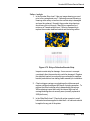
Gate Array
Figure 2-6. Gate Array.
The gate array contains the hardware logic for dot firing, monitoring
changes in the Carriage Assemblies position, controlling DMA through
the parallel port, and generating the PWM (Pulse Width Modulation)
waveforms for the servo controller. It also controls the stepper motor,
LCD and keypad.
The gate array is a Xilinx device. It is a static RAM-based field programmable gate array. This means that the logic that it implements is
determined by configuration information in internal RAM storage. Each
time power is turned on, this information must be downloaded from the
system ROM. This type of gate array allows for the flexibility of
upgrading the logic by simply downloading the new system software.
Digital Signal Processor (DSP)
The DSP converts raster data into the head buffer data format used by
the printheads. The gate array tells the DSP when to send data to the
carriage. The DSP runs at 192 MHz. It has 32M of dedicated SDRAM
that is separate from the DIMM the PowerPC uses.
Theory of Operation
2-9
NovaJet 800 Series Service Manual
Memory Circuits
Memory is used to retain large amounts of information. This information
is stored in the device memory in the form of binary bits.
Printer memory consists of Flash EEPROM, SDRAM, and EEPROM.
Maximum installable memory is as follows:
SDRAM = 256 MB
Flash EEPROM = 2 MB
Serial EEPROM = 1KB
Flash EEPROM
Flash EEPROM is Electrically Erasable, Programmable, Read Only
Memory used to store instructions and data constants which the microprocessor can access and interpret, with no loss of information when
power is off.
The system firmware is stored in Flash EEPROM. The Flash EEPROM
allows the firmware to be upgraded by downloading the files containing
the new firmware. It can be erased and reprogrammed more than 10,000
times. The term “Flash” means that bytes cannot be individually erased.
A block or the whole device is erased at the same time and the block or
whole device is then reprogrammed.
The normal method of downloading new firmware is to send the unit the
files containing the code using either the GO.EXE utility or printing the
file to the unit. This requires using an appropriate host utility and can be
done through the parallel port. See Firmware Downloading in Chapter 3
for the procedures.
Theory of Operation
2-10
NovaJet 800 Series Service Manual
SDRAM
SDRAM is Synchronous Dynamic Random Access Memory, which
provides temporary storage of the microprocessor calculation and input/
output data. It is also a faster type of memory then the Flash
EEPROM. That’s why the printer control program is also copied from
the Flash EEPROM to RAM, where it can be executed faster.
All printers ship with 64 MB of RAM and are upgradable to a maximum of 256 MB. Additional memory helps to free the host computer
more quickly. Printer memory may be upgraded by installing PC100 (or
faster) 168-pin DIMMs or Dual In-line Memory Modules. The printer
will accept 64 MB, 128 MB or 256MB DIMMs.
Serial EEPROM
Serial EEPROM is an Electrically Erasable, Programmable, Read Only
Memory which provides storage for calibration constants and user
configuration data entered from the host computer.
An 8K bit serial nonvolatile EEPROM stores calibration and configuration information. It retains data while the unit is off.
Stepper Motor Controller
Figure 2-7. Stepper Motor Controller.
The media is driven by a Stepper Motor, which drives the media in a
direction perpendicular to the width of the printer. The media in the
printer can advance forward and backward, depending upon the
Theory of Operation
2-11
NovaJet 800 Series Service Manual
commands which the Stepper Motor receives from the microprocessor.
The Stepper Motor Controller contains two identical circuits, one for each winding of the
stepper motor. The circuit is a combination of two simpler types of circuits and can be
thought of as a variation of either one.
A waveform generator receives digital data from the gate array and generates a sine
wave output. This signal is fed into a comparator circuit that is measuring the current
through the winding of the stepper motor. If the current is too low, a pulse of 24V is
generated. When the current goes above the output of the waveform generator, the pulse
turns off. Every time the output of the waveform generator is changed by the microprocessor, the motor moves 1 “micro-step”.
Each circuit contains four main functions (see Figure 2-7):
1. Reference waveform generator - the gate array uses a D/A (digital to analog)
converter to set the desired level for the current in the stepper motor winding. The
output of the D/A converter varies in time to create a reference waveform. This
reference waveform is centered around 2.5V.
2. Motor current sense - the voltage across a series current sense resistor is measured and level shifted so that it is centered around 5V.
3. Comparator - this portion divides the output of the reference waveform generator
by two and compares it to the output of the motor current sensor. Logic inside the
gate array generates the control signals for the power driver that applies voltage
across the motor winding in order to make the actual current match the reference
waveform.
4. Power driver - an H-bridge allows the supply voltage to be applied across the
winding in either polarity used to drive the current level to the desired value.
Theory of Operation
2-12
NovaJet 800 Series Service Manual
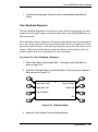
Servo Motor Controller
GATE
ARRAY
MOTOR
DRIVER
SERVO
CONNECTOR
SERVO
MOTOR
CARRIAGE
CONNECTOR
ENCODER
CARRIAGE
MAIN PWA
Figure 2-8. Servo Motor Controller.
The Carriage Assembly is driven by the Servo Motor. The speed of the
Carriage Assembly is controlled by varying the duty cycle of the signal
applied to the controller. The microprocessor checks the position of the
Carriage Assembly approximately 1,000 times per second (during the
servo interrupt). It then updates the PWM (pulse width modulator)
register in the gate array which sets the duty cycle to make adjustments
to the Carriage Assembly speed. A linear optical encoder is used to
monitor the Carriage Assembly position.
The optical encoder strip runs the length of the Stabilizer Bracket and
contains 150 lines and spaces per inch. Thus there are 300 edges per
inch. The detector circuit actually consists of two optical edge detectors.
They are separated from each other by one half the width of one of the
optical lines on the encoder strip. This allows 4 evenly spaced pulses to
be developed for each line on the encoder strip. This is known as quadrature signals. It gives an effective resolution of 600 lines per inch. See
Figure 2-9 for a graphical representation of quadrature signals.
Maximum velocity of the Servo Motor is 46.6 inches per second (IPS).
Servo Motor life is rated to 2.8 million cycles or approximately 2800 plot
hours.
Theory of Operation
2-13
NovaJet 800 Series Service Manual
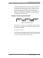
DETECTOR 2
DETECTOR 1
ENCODER STRIP
OUTPUT OF DETECTOR 1
OUTPUT OF DETECTOR 2
COMPOSITE TRANSITION-TRIGGERED OUTPUT OF BOTH DETECTORS
4 OUTPUT PULSES
PER OPTICAL LINE
Figure 2-9. Quadrature Signal Generation.
The direction that the Carriage Assembly is moving is calculated based
upon the state of one detector’s output and the direction of the transition
of the other detector’s output.
Theory of Operation
2-14
NovaJet 800 Series Service Manual
A hardware counter in the gate array increments as the Carriage Assembly moves left and decrements as the Carriage Assembly moves right.
The hardware counter is only eight bits wide, so it cannot store a value
large enough to represent an absolute Carriage Assembly position.
Instead, it is read during the servo interrupt and its value compared with
that from the previous interrupt. This difference is used to update the
absolute position value in the software.
Interface Circuits: Serial & Parallel
MICROPROCESSOR
GATE
ARRAY
PARALLEL
CONNECTOR
Figure 2-10. Interface Circuits.
Data from the host computer is received through the Centronics parallel
port. The gate array provides the control signals for DMA transfers from
the parallel port to SDRAM.
The serial port is not used.
Possible solutions for the Macintosh computer user include using the print
server device with an established network or installing a parallel port addon card in the computer to interface with the printer.
Theory of Operation
2-15
NovaJet 800 Series Service Manual
Carriage Assembly Circuits
OPTICAL ENCODER
OPTICAL SENSOR
TRAILING
CABLE
PAPER SENSOR
TRAILING
CABLE
CONNECTION
FROM
MAIN
PWA
CARRIAGE
PWA
RIGHT CARRIAGE
ASSEMBLY ONLY
CARTRIDGE 1
INKJET
DRIVERS
CARTRIDGE 2
CARTRIDGE 3
CARTRIDGE 4
LEFT AND RIGHT CARRIAGE ASSEMBLY
Figure 2-11. Carriage Assembly Circuits.
The Right Carriage Assembly contains:
1)
2)
3)
4)
Carriage PWA
Optical Sensors
Paper Sensor
Inkjet Cartridges
The Left Carriage Assembly contains:
1) Carriage PWA
2) Inkjet Cartridges
Theory of Operation
2-16
NovaJet 800 Series Service Manual
NOTE: The carriage housing has been modified from that of the Right
Carriage Assembly. The belt strain relief has been removed and the
encoder sensor clip has been removed.
The Right Carriage PWA contains the logic and drive circuitry for the
firing of the inkjet cartridges. It also establishes an interface path for
the optical sensor and paper sensor to communicate with the Main
PWA.
The optical sensors receive their inputs from the optical encoder strip
and sends this data to the Main PWA. The Main PWA uses this
information to determine the horizontal position of the carriage assembly so that accurate printing can be established.
The paper sensor circuitry senses for the presence of loaded media. It
does this automatically during the start-up and load sequences. It also
constantly monitors the media during printing to determine if the media
has run out.
If no paper is sensed, the paper sensor sends this information to the
Main PWA, which immediately begins an ‘out of paper’ subroutine.
This subroutine stops the printer from printing until more media is
loaded. NOTE: Space lighting must be at a constant level or the paper
sense circuitry will create an error and print operations will cease.
The sensor also checks for the size of the media loaded so it can
determine the proper printing parameters.
The Green LED on the Right Carriage and Left Carriage PWA indicates the proper drive voltage is available for the driver ICs. It is dim
when the printer is idle but becomes bright during printing.
Theory of Operation
2-17
NovaJet 800 Series Service Manual
Control Panel
The Control Panel is located on the right side of the printer and consists
of 8 variable-action control buttons and an LCD graphics display. The
control buttons are assigned to different functions and are dependant
upon the selections that were previously selected. There are four buttons
on the left of the display and four buttons on the right, with the display
showing up to eight possible selections.
Load Media
*
Feed Media Menu
Cut
Setup Menu
Pause
Utility Menu
Reset
Figure 2-12. Main Menu.
Figure 2-12 shows the keypad after the printer has been turned on and
finished the start up process. As seen in the figure, the control buttons are
assigned to the corresponding command that is displayed closest to the
physical location of the button.
Power Supply
An internal UL recognized switching power module supplies power for
the printers. It provides a constant 24VDC output from input voltage in
the 90-132 VAC and 180-246 VAC ranges. A power switch turns the
power on and off. The 24VDC is applied to the MPCB where it is
further regulated and separated into 1.8VDC, 3.3VDC, and 5VDC. The
24V supply is used for: the stepper controller (which advances the
paper); the servo controller (which moves the Carriage); and power to
fire the inkjets. The 5V and 3.3V supply powers the logic circuits. The
1.8V powers the DSP.
Theory of Operation
2-18
NovaJet 800 Series Service Manual
The power supply is fused using a 6.3A 250V fast blow type fuse.
The outputs share a common ground which is isolated from earth ground
with in the supply itself. Earth ground and DC ground are connected
external of the power supply.
The power supply will shut down under overload/short circuit conditions
on any output over the full range of input voltage. Overvoltage protection
is 20%-30% above nominal for the 24V output.
Thermal Dryer Assembly
To ensure prints are dry for unattended printing, the printer features a
thermal (hot air convection) drying system. The system monitors the
temperature and humidity in the environment and adjusts the heat to
optimize drying time and ensure consistent image quality. The fans blow
air past 1200 watt heating elements, quickly drying the media. The dryer
effectively dries prints up to 100 sq/ft/hr @ 250% ink saturation. The
dryer system easily mounts to the stand assembly. The dryer logic cable
connects the dryer to the right leg logic jack. The dryer power cord plugs
into the power entry module at the rear of printer.
The thermal drying system is composed of the dryer plenum, logic cable,
and Main PWA (humidity and temperature sensors). The dryer typically
stays on for approximately 3 minutes following a print job when the Dryer
is in the on mode. Auto-Cut Delay is the time set between successive
print jobs (dry time between prints).
The Dryer PWA has two thermistors which provide feedback to the Main
PWA firmware to raise or lower temperature inside the plenum. The
firmware in turn drives the dryer PWA Triac (attached to heatsink) to
deliver the current to the two 1200-watt heating elements. The dryer
may be turned on, off, or placed into the auto-mode. The maximum
temperature obtainable is approximately 52 degrees Celsius. The 60" unit
runs a little cooler than the 42" platform due to the additional length of the
1200-watt heating elements (twin 500 to 600 watt elements). The glass
fuse on the Dryer PWA will normally fail before an active component due
to an overcurrent condition.
Theory of Operation
2-19
NovaJet 800 Series Service Manual
The Main PWA has a humidity sensor and a temperature sensor mounted to the
back side. The sensors monitor ambient room temperature and humidity. Prior to
print operations the printer should be allowed to acclimate to the environment for
at least 15 minutes. The plenum may be preheated using the F6 key (2nd key
from the top at right side of control panel) under the Sensor Status Menu.
The Dryer PWA is internal to the right side of the dryer plenum. The green LED
(D2) on the Dryer PWA indicates that the triac is functioning properly and that
power is applied to the two heating elements.
Sensor Status Menu
From the top-level menu of the printer, navigate the menu tree as follows.
Utility Menu
Service Menu
Diagnostic Menu
Accessory Menu
Sensor Status
The printer LCD will display the following information:
Dryer Mode: cccccccc
Plenum T. = ## deg. C
MBoard T. = ## deg. C
MBoard H. = ## pct. RH
Available mode readouts include: On, Off, Auto and Disabled.
The optical sensors are designed to inform the Main PWA when there is not a
proper amount of slack in the media by sensing the ‘curl’ of the media at the
bottom of its loop. This method is used so that all approved forms of media
(including transparent backlit media) is able to take advantage of the power feed
and take-up system.
Theory of Operation
2-20
NovaJet 800 Series Service Manual
Beeper and Fans
The beeper contains built-in driver circuitry so that it beeps under firmware control. The beeper alerts the user to error conditions.
There exists three types of fans that can be on these printers.
A single fan, located below the power supply, is used for cooling the
power supply. Air blows over the power supply and the heated air is
forced out the back of the printer. It also blows air on the temperature
and humidity sensors so they can measure ambient conditions more
accurately.
A fan is located inside the platen with its fan vent seen from under the
platen on the right side of the printer. This fan provides suction on the
platen bed and holds the paper (media) flat during the printing process.
The 60 inch model has an additional suction fan located near the center of
the printer inside the platen.
Two fans are located inside the dryer plenum body to draw ambient air
inside to be heated. These fans are tested when power is applied to the
printer.
Theory of Operation
2-21
Maintenance
3
Introduction
This chapter contains general maintenance and cleaning instructions for
the NovaJet 800 series printers.
Scheduled Maintenance
Scheduled maintenance consists of a list of checks that are planned to
be performed on a regular basis or when conditions warrant it.
Scheduled maintenance can be thought of as preventive maintenance
since its purpose is to prolong the life of the printer. It is not intended to
repair or isolate an existing problem, though it can sometimes be helpful
in detecting a condition due to a weakened component that has not yet
completely failed.
Below is a list of scheduled maintenance checks and their recommended periodicity.
Clean external areas:
Clean slide shaft:
Clean service station:
Clean encoder strip:
Clean trailing cables:
Clean platen surface/vacuum holes:
Clean cartridge dimples:
Clean flex cable contacts:
weekly, or as required
weekly
daily
weekly
bi-weekly
monthly
if prime fails
if prime fails, or cartridge
is replaced
Clean and inspect motor gears:
annually
Clean and inspect Main PWA:
annually
Clean and inspect carriage assembly:
annually
Clean dryer assembly
monthly
Reseat connectors on Main PWA:
annually
Reseat connectors on carriage boards: annually
Replace trailing cables
every 2000 plot hours
Replace carriage cover bushings (2 total):every 2000 plot hours
Replace carriage bushings (4 total)
every 4000 plot hours
3-1
NovaJet 800 Series Service Manual
Cleaning Procedures
Always turn the printer OFF, remove the power cord and the interface cable before cleaning the printer. An electrical shock hazard
may be present if these procedures are not followed.
External Cleaning
Do not use abrasive cleansers of any sort on the surfaces of the
printer. Damage to the surface may result.
The exterior surfaces of the printer may be cleaned with a soft cloth which has
been dampened. For more persistent stains, a small amount of liquid detergent
may be used. Cleaning intervals are determined by the environment in which the
printer is used.
Slide Shaft Cleaning
Use only isopropyl alcohol on the slide shaft of the printer. Damage to the stainless steel slide shaft may result if cleaned with water and not completely dried off.
Maintenance
3-2
NovaJet 800 Series Service Manual
Printer problems can be caused by an accumulation of dirt or other contamination on
the slide shaft. This contamination may lead to drag on the carriage. Extreme drag
results in a “carriage axis failure” fault and will stop the carriage motion. These
problems may be eliminated by maintaining and cleaning the slide shaft at intervals
determined by the environmental conditions. Do not use any lubrication.
To clean the slide shaft:
1.
Turn the printer OFF. Disconnect the power cord and interface cable.
2.
Raise the printer lid.
3.
Moisten a clean cloth or paper wipe with isopropyl alcohol.
4.
Wipe the length of the slide shaft with the moistened cloth or wipe.
5.
Manually move the carriage assembly from side to side.
6.
Wipe the shaft again to remove any deposits left from the carriage.
7.
Close the cover and reconnect the power cord and interface cable, turn the
printer ON and perform the PRIME procedure. Be sure that the carriage moves
freely on the slide shaft.
Service Station Cleaning
Ink and dust may build up on the service station, resulting in contamination which may
smear the prints. The service station is cleaned as follows:
1.
Turn the printer OFF. Disconnect the power cord and interface cable.
2.
Raise the printer lid.
3.
Carefully move the carriage toward the center of the printer.
4.
Using a cotton swab dampened with distilled water, wipe the seals and the
rubber wiper in the service station until no more ink residue or dust can be
removed.
5.
With a dry swab, wipe all moisture from the seals and wipers.
6.
Close the lid and reconnect the power cord and interface cable.
Maintenance
3-3
NovaJet 800 Series Service Manual
7.
If the service station is filling with ink or very dirty it can be removed and rinsed
under warm water. To remove, pull the tab on the right side of the service station
and lift out. Wash, dry thoroughly and replace by placing the left side in first then
pushing down on the right side until the tab locks it in place.
Linear Encoder Strip Cleaning
Clean the linear encoder strip weekly or as necessary to remove any buildup of debris.
Distilled water or isopropyl alcohol may be used. You may notice that it tends to fog the
encoder strip; however, no detrimental effect has been observed in the field.
To clean the Encoder Strip:
1.
Disconnect the power cord and interface cable.
2.
Slightly dampen a cotton swab with distilled water and wipe along the length of the
encoder strip on both sides. Do not use denatured alcohol, MEK, acetone or
keytone substances on the encoder strip as this is known to have caused damage
to the encoder strip.
3.
Reconnect the power cord and interface cable.
Figure 3-1. Encoder Strip Cleaning.
Maintenance
3-4
NovaJet 800 Series Service Manual
Trailing Cables Cleaning
Clean the trailing cables bi- weekly or as necessary to remove any buildup of debris.
Distilled water should be used. Do not pull too hard on the trailing cables or damage
may occur.
To clean the Trailing Cables:
Disconnect the power cord and interface cable.
2.
Slightly dampen a lint-free cloth with water and wipe along the length of the
trailing cables on both sides. Ensure the encoder stabilizer bracket surface is
thoroughly cleaned. Clean the lower surface of the rear cover on the left side
of the printer.
3.
Reconnect the power cord and interface cable.
MAINTENANCE
1.
Platen/Vacuum Hole Cleaning
To clean the external surfaces of the printer. Dampen a lint-free cloth with water
and wipe all surfaces of ink and debris. Ensure the platen surface is thoroughly
cleaned.
To clean the platen vacuum holes obtain a toothpick and gently remove lint and media
fiber from platen holes. Caution: do not push lint through platen holes or problems
with the stepper motor gearing may eventually occur leading to microbanding in
image output.
If the platen holes are not cleaned periodically then adequate vacuum suction be not
be available to pull media down during print operations.
Maintenance
3-5
NovaJet 800 Series Service Manual
Cartridge Dimples Cleaning
CARTRIDGE
DIMPLE
AREA
Figure 3-2. Cartridge Dimple Region.
The cartridge dimple area can easily be contaminated by oils and dirt on
fingers and hands or ink spilled onto them. This causes the cartridges to
not receive some of the electrical signals for a proper firing of the jets.
This can be seen as a misfiring of the cartridge.
NOTE
Care should be used when handling the cartridges. Avoid
touching the cartridges on the dimple area or on the inkjet
holes on the bottom. The oils and dirt on fingers and hands
can contaminate the area and result in misfiring of the inkjets.
Clean the cartridge dimple area by gently dabbing the area with a lint free
cloth or cotton swab saturated with isopropyl alcohol.
Maintenance
3-6
NovaJet 800 Series Service Manual
Be sure to clean the yellow cartridge because it is not readily apparent that it is
dirty. The yellow ink is hard to see and could be overlooked.
Flex Cable Contact Cleaning
MAINTENANCE
Flex Cable Contacts
Figure 3-3. Flex Cable Contacts.
Cleaning the flex cable contact area is very important due to the ease with which
this area can become dirty. The flex for the yellow cartridge is deceiving because
it is not readily apparent that it is dirty. This also causes the cartridges to not
receive all of the electrical signals for a proper firing of the jets. This can be seen
as a misfiring of the cartridge.
NOTE
Be careful when handling the flex cable contact area. Avoid touching the contact area because oils on your skin can contaminate the
area and result in misfiring of the inkjets.
Clean the flex cable contacts by gently dabbing the area with a cotton swab soaked
with isopropyl alcohol.
Maintenance
3-7
NovaJet 800 Series Service Manual
Clean and Inspect Stepper Motor Gears
The stepper motor gears can become dirty after time (typically after 4-5 years of
operation) if not cleaned. Dirty gears can cause microbanding in the print. This will
reduce the quality of the output. Clean the motor gears with a stiff brush to knock off
any debris. A cotton swab soaked isopropyl alcohol can be used to remove any ink that
may have accumulated on the gears.
Clean and Inspect Main PWA
Foreign material on the Main PWA could short out electrical signals being developed on
the Main PWA and cause erroneous prints or even damage to the Main PWA. All
electrical circuits should be free of foreign material, especially those materials with
conductive properties.
Clean the Main PWA by blowing the objects away or gently brushing them aside with a
soft brush if required.
Inspect the Main PWA for any damage to the board, connections, or any of its components . Replace the board if inspection reveals any damage or flaws that could affect its
function .
Clean and Inspect Carriage Assembly
Foreign material on the carriage assembly could short out signals being developed on the
carriage assembly and cause erroneous prints or even damage to the carriage assembly.
A very common problem occurs when ink has been spilled onto the carriage assembly.
All electrical circuits should be free of foreign material, especially those with conductive
properties.
Clean the carriage assembly by blowing the objects away or gently brushing them aside
with a soft brush if required. Be careful not to let anything to fall into the printer as you
clean or it could cause a new problem.
Inspect the carriage assembly for any damage to the boards, connections, or any of the
components on the assembly.
Maintenance
3-8
NovaJet 800 Series Service Manual
Dryer Cleaning
To clean ink and debris from the dryer, use a lint-free cloth dampened with water.
Clean all external surfaces with the exception of the underside of the dryer.
Reseat Connectors on Main PWA and Carriage Boards
MAINTENANCE
Integrated circuits may become weakened or damaged by electrical discharge. Do not touch or work near integrated circuits without wearing an ESD wrist strap.
Ribbon connectors can be easily damaged if incorrectly handled.
Observe extreme caution when handling the ribbon connectors to
avoid damage.
Many problems can be corrected simply by removing and reseating connections
found in circuit assemblies. This process helps to clean the contacts and can
dissipate any static electrical charges that might have developed.
Maintenance
3-9
NovaJet 800 Series Service Manual
J 5
J 1 8
J 2
J 1 7
J 4
J 1 5
J 1 3
J 1 1
J 1
J 1 J2 6
J 8
J 7
J 1 0
U 2 4
J 9
Figure 3-4. Main PWA Connection Locations.
Table 3-1. Main PWA Connections.
J1
J2
J3
J4
J5
J6
J7
J8
J9
U24
Trailing Cable A
Trailing Cable B
not used
Vacuum Fan #2
Parallel Port
Leg Harness
Stepper Motor
Power Supply
Keypad
PC133 SDRAM DIMM
J10
J11
J12
J13
J14
J15
J16
J17
J18
socket
Display
Serial Port
Servo Motor
AutoLoad Sensor
not used
Vacuum Fan #1
not used
Power Supply Cooling Fan
E-Connect Power
Maintenance
3-10
NovaJet 800 Series Service Manual
J 7
J 6
J 5
J 3
J 4
MAINTENANCE
J 2
J 1
Figure 3-5. Carriage PWA Connection Locations.
Table 3-2. Carriage PWA Connections.
J1
J2
J3
J4
Trailing Cable
Paper Sensor
Encoder Sensor
Black/Slot 1 Drivers
J5
J6
J7
Cyan/Slot 2 Drivers
Magenta/Slot 3 Drivers
Yellow/Slot 4 Drivers
Figures 3-4 and 3-5 show the locations of all the connectors on the
Main PWA and carriage boards respectively. The J2 and J3 jack
connections shown on Figure 3-5 are used on the right carriage assembly only.
To remove the ribbon cables from their connectors, lift the connector’s
ribbon locking mechanism as shown in Figure 3-6. To reattach, depress
the locking mechanism back into the locking position after inserting the
ribbon cable end.
Maintenance
3-11
NovaJet 800 Series Service Manual
RIBBON
LOCKING
MECHANISM
UNLOCKED
LOCKED
CONNECTOR
ASSEMBLY
Figure 3-6. Ribbon Connector Locking Mechanism.
Replace Trailing Cables
Before replacing the trailing cables from the printer always remove power
from the printer.
The trailing cables (2 total) are rated for approximately 2000 hours of operational usage.
Many factors including, but not limited to, hours/day used, cleanliness of the trailing cable
surfaces and general ambient environment make it impossible to calculate the average
time that the trailing cables will last. If the trailing cables are cleaned weekly the life of
the cables should effectively double.
If not replaced, the wear on the trailing cable flexible printed circuits can result in erratic
carriage motion and/or carriage axis failures, vertical white bands (jumps) in printed
output, vertical color band jumps, and unrecognized cartridge error messages. Cables
should always be replaced in sets (never replace one cable only).
To replace the trailing cables, follow the procedures for Trailing Cable Replacement
found in Chapter 5.
Maintenance
3-12
NovaJet 800 Series Service Manual
Replace Carriage Cover/Carriage Bushings
The carriage cover bushings (2 total) are rated for approximately
2000 hours of operational usage while the carriage assembly
bushings (4 total) are rated for approximately 4000 hours of operational usage. Many factors including, but not limited to, hours/day
used, cleanliness of the slide shaft and general ambient environment
make it impossible to calculate the average time that the carriage
bushings to last.
MAINTENANCE
If not replaced, the wear on the bushings can result in erratic
carriage motion and/or carriage axis failures. It can even cause the
cartridge head height to become uneven.
To replace the carriage bushings, follow the procedures for Carriage Cover Bushing and Carriage Bushing Replacement found in
Chapter 5.
Maintenance
3-13
NovaJet 800 Series Service Manual
Servo Motor Winding Resistance Check
Figure 3-7. Servo Motor.
1.
Disconnect the servo motor connection from J12 on the Main
PWA.
2.
Using a standard ohmmeter or multimeter, connect the meter
leads to the two wires going to the motor.
3.
While manually rotating the servo motor, monitor the readings on
the meter. The acceptable range is 2-12 ohms. Typically, the
reading is 3-8 ohms.
4.
If the measurement is found to be unsatisfactory, replace the servo
motor.
Maintenance
3-14
NovaJet 800 Series Service Manual
Stepper Motor Winding Resistance Check
MAINTENANCE
B
A
*
Figure 3-8. Stepper Motor.
1. Disconnect the stepper motor connection from J7 on the Main
PWA.
2. Using a standard ohmmeter or multimeter, measure between
pins 1 (red wire) and 3. Point A in Figure 3-8. The asterisk in
Figure 3-8 identifies the red wire.
3. The reading should indicate 7.2-8.0 ohms.
4. Continue by measuring between pins 4 and 6. Point B in
Figure 3-8.
5. Reading should also indicate 7.2-8.0 ohms.
6. If either measurement is out of tolerance, replace the stepper
motor.
Maintenance
3-15
NovaJet 800 Series Service Manual
Power Feed and Take-Up Motor Winding Resistance Check
Figure 3-9. Power Feed and Take-Up Motor.
1.
Remove the feed and/or take-up roll from the printer.
2.
Using Phillips screwdriver, remove the four screws that secure the
cradle idler from the right leg.
3.
Ease the cradle idler off of the leg enough to disconnect the
motor wires from the leg harness.
4.
Using a standard ohmmeter or multimeter, measure between the
+ and - connections on the motor. While manually rotating the
servo motor, monitor the readings on the meter. The acceptable
range is 25-40 ohms. Typically, the reading is 29-36 ohms.
5.
If the measurement is found to be unsatisfactory, replace the
motor.
6.
Perform the same procedure on the remaining motor.
Banding: Hardware vs Software
The technician must be able to identify whether the banding that is being
observed is related to either a hardware or a software problem. The two
examples in Figure 3-10 represent classic types of hardware and
software banding errors.
Maintenance
3-16
NovaJet 800 Series Service Manual
Banding Differences
MAINTENANCE
Consistent horizontal banding is usually hardware related. Normally
horizontal microbanding is caused by improper color deadband or color
calibrations, dirty cartridges or service station. Inconsistent banding is
usually software related. However, electrostatic discharge (ESD) from
media (i.e. Backlit/Duratrans films) can also cause inconsistent horizontal
banding. While minimal microbanding in an image typically occurs due to
cartridge jet failures and clogs, dirty service station or an improper calibration of the printer, gross microbanding can be caused by a dirty encoder
strip causing image skew or real hardware failures.
Vertical banding is always hardware related. Diagonal banding could be
either hardware or software.
HARDWARE
SOFTWARE
Figure 3-10. Examples of Horizontal Banding.
Hardware banding is usually characterized by consistent banding strips as
shown. Typically horizontal banding is caused by the cartridge or print head
in 95% of the cases. It signifies a slippage in the media’s normal movement
that is possibly due to the stepper motor, lower drive shaft assembly, pinch
rollers, or the rollguides on the back of the printer. All these possible faulty
areas deal with a rotational movement that, if faulty, will generate a consistent banding pattern. The Main PWA and Carriage PWA can also cause
this type of error to occur.
Software banding is characterized by inconsistent banding lines or lines
which violate the page layout (extend beyond the print border). These
Maintenance
3-17
NovaJet 800 Series Service Manual
banding lines are generated by the software when the application incorrectly interprets
the media advancing/ink firing sequence of the expected print file or when text an error
occurs within the host application. Errors can also be caused by insufficient host
workstation or RIP memory or processing power. Because it is not directly tied to a
mechanical movement, the bands become inconsistent in both frequency and duration.
The possible causes are the printer driver, the original software package, or the RIP, if
one is used. To eliminate the chance that it is the printer driver:
1)
Remove any RIP or network systems and connect the printer directly to the
computer via the printers parallel port.
2)
Print a test file approved by ENCAD that uses only the ENCAD print file utility
version 3.0 (EFPU 3.0) and the ENCAD printer. Send a test file via LPT1 with
ECP mode enabled with DMA channel assignment.
If the test file prints correctly, the problem lies in either the software package that
generated the print or the RIP, if used. The problem could also be with the built-in EConnect print server or with the workstation transmitting the print data directly to the
printer’s parallel port. To eliminate the E-Connect print the Semi-Circular Nook test
pattern by quickly depressing the TEST button at right rear of printer (Ensure the short
(15”/39 cm) parallel printer cable is attached between parallel ports prior to activating
the test.
A simple test to determine if the banding is caused by the computer/RIP/application or
the printer is to rotate the image 90 degrees and see if the banding rotates or remains in
the same orientation as the previous print. If the banding does not rotate, then look for
causes in the printer. If the banding does rotate with the image, then look for causes in
the computer/RIP or application.
Maintenance
3-18
NovaJet 800 Series Service Manual
Banding Causes & Quick Analysis
Horizontal Banding Problems
MAINTENANCE
1. Check the print mode for the type of image being printed. Refer to
Printer Calibrations - 'Checking Print Mode'. Is the high pass mode
(5 pass for 2x4 configuration, 10 pass for 1x4, 1x6, and 1x8 cartridge
set configurations) printing successful? Note: 3 pass mode (2x4
configuration) or 4 pass mode (1x4, 1x6, and 1x8 cartridge set
configurations) will microband in many of the 2 tone color ranges
including some blue, gray, orange, and purple hues. Check to see if
the media is loaded correctly and is of proper thickness (no greater
than 20 mil media can pass through the machine). Check to see if
the media guides are in place and are not defective. Check the pinch
rollers for alignment/damage.
2. Are the color deadband and color calibrations correct? Refer to
Printer Calibrations. Inspect the Prime pattern and verify diagonal
line in the jet test is consistent throughout. The line should not have
sections or lighter and darker shades, it should not be dissolved or
broken. Refer to Printer Features - 'Jet Out Detection'. Clean,
manually bypass clogged jets, or replace the cartridge if any of these
abnormal conditions exist. Defective or clogged cartridges account
for 90% of the banding observed.
3. Change the preheat setting for the affected color. To gain access
select SetUp Menu, Ink Option Menu, Ink PreHeat Settings, choose
the appropriate color. If this does not help, then return settings to
zero (0) default at completion of test.
4. Ensure the Auto-Wipe feature is turned off. To gain access select
SetUp Menu, Paper Option Menu, Auto-Wipe, select off. Auto-Wipe
of the carriage head (occurs every 2 minutes when activated) can
cause a dry band to appear on the print. This feature is normally
defaulted off. The printer will normally spit into the service station
every 15 seconds (GO or GX ink loaded) or every 2 minutes (GS+ ink
loaded) to keep nozzles clear but will not interfere with print and dry
time to cause banding of any nature.
Maintenance
3-19
NovaJet 800 Series Service Manual
5.
Clean the cartridge electrical and carriage flex driver cable
contacts with isopropyl alcohol. Refer to Scheduled Maintenance.
Reseat the flex driver cable connection for print images which
contain vertical bar patterns along the right edge of print. If more
than one color (represented by the vertical bars) is present then
the trailing cable is either unseated or defective.
6.
Clean the encoder strip (top and bottom) and inside of carriage
belt with distilled water. Clean the slide shaft with isopropyl
alcohol.
7.
Change media to see if electrostatic discharge from media is
causing the banding to occur. Add 3rd party protection if required.
8.
Ensure vacuum fan is providing adequate suction for media. It is
possible that binding of the feed roller may also occur (leading to
microbanding and abnormal print anomalies) if the stand legs are
not secured to the printer head securely. A rocking motion (from
the weight of the carriage assembly movement during printing) is
created which can cause shifting of the printer base.
9.
Turn printer off. Slowly move carriage head back and forth
manually to ensure no obstructions are causing the print defects
observed (i.e. tape on the rear cover, tie-straps under the
electronics cover, or low carriage head height).
10. Check E-Connect Print Server. Carriage head hesitation (which
causes microbanding) is normally caused by a low data port rate
(information cannot get through the print server fast enough).
While the E-Connect is rated for 700 kilo bytes per second (fast
enough to handle any large format demands at the fastest printer
speed available), an improperly configured server or a server in a
high traffic environment may be the cause of the microbanding.
Test printer with limited or no network traffic to verify. Reconfigure
the E-Connect if necessary and turn off any redundant or unused
protocols. Please consult a network administrator for assistance.
11. Print a test RTL file to verify banding, if banding is absent, then
check software. Obtain the Demo Images CD and refer to the
Multimedia Operations CD - 'Demonstration Print' for proper
procedure. Print at least 50% of the test print (1/2 meter long)
before deciding the next course of action. The Test Print (Utility
Maintenance
3-20
NovaJet 800 Series Service Manual
Menu, Service Menu, Test Print) may be used, but this test is a
compressed vector based file and may exhibit certain dithering
properties different from that of another rasterized print.
12. Refer to 'Cartridge Misfires' and 'Ink Dropout' to ensure all other
troubleshooting checks have been made.
MAINTENANCE
13. For single color or multiple color print failures replace the carriage PWA.
If normal test patterns (i.e. Color Test and normal basic test patterns) are
seriously degraded then replace the carriage PWA. Refer to
Disassembly.
14. Inspect and clean stepper motor and lower roller drive gears if printer is
older than 5 years. Other unique causes include synchronization errors
from the stepper drive system due to defects or gear cleanliness.
15. Replace stepper motor for consistently spaced horizontal patterns (2 10 mm apart) when printer is run in the best mode with a test print.
Often a lower roller drive noise will accompany the banding. Inspect
stepper motor gearing/lower roller for damage/debris (ensure screws are
tight).
Check stepper motor winding resistance.
16. Check lower roller height for head scrapes on media. Banding will have
jagged or slightly angled lines at the termination points or may even
appear as light cuts in the media (like a utility knife cut the surface of a
print). The normal head height range between the bottom surface of the
cartridges and the platen surface is 0.062" to 0.068". Use the Carriage
Head Height Kit for proper adjustment. Refer to Alignments.
17. Replace the servo motor for horizontal bands (thicker than 2 mm) which
extend beyond the page layout from .5 mm to 20 mm. The servo motor
bearings may be faulty; normal servo motor life is 1600 to 2500 plot
hours. Horizontal bands (0.2 mm to 1 mm) which extend beyond the
page layout are usually caused by the workstation memory or the driver
not having sufficient work space. Ensure 1GB is free on hard drive at all
times; 256 MB of memory is suggested. Partitioning the hard drive is
recommended. Refer to Disassembly.
Maintenance
3-21
NovaJet 800 Series Service Manual
18. Clean or replace encoder strip for image skewing (image walking or skipping).
Whether the image skews slights or off the page the encoder strip is at fault.
Typically characterized as horizontal banding, often a walking image can also
create vertical bands to appear in the print. Refer to 'Scheduled Maintenance' for
cleaning or 'Disassembly' for encoder strip replacement.
19. Improper grounding or earthing. An improper A/C outlet power ground may cause
banding due to excessive noise on the line between the neutral and ground.
Ensure the outlet has a clean zero ground potential with minimal noise between
the neutral and ground.
20. Replace Main PWA for severe horizontal and vertical banding patterns. Refer to
Disassembly.
Vertical Banding Problems
1.
For vertical banding check carriage bushings for wear and ensure the bushings
are free of dirt and ink residue buildup. Perform the carriage vibration test under
'Diagnostics' Menu, the lines should print fine with no jagged edges. Clean the
bushings with a dry lint-free towel if necessary. Replace both carriage bushings.
Refer to Disassembly.
2.
Rotate image in software 90 degrees and/or print a test RTL file to verify banding.
Obtain the Sample Images CD and refer to 'Demonstration Print' for proper
procedures.
3.
Replace the trailing cable prior to any circuit assembly replacement. Replace
trailing cable for vertical jumps in color (i.e. one color does not print through one
part of the print, the image appears to have a vertical pattern) or for vertical white
spaces down a print. Replace the trailing cable if multiple sets of vertical bars
appear along the right edge of the print, usually containing CMYK colors. The
image may also be 'pushed' slightly to the left side of the printing area. Refer to
Disassembly.
4.
Clean or replace encoder strip for image skewing (image walking or skipping).
Typically characterized as horizontal banding, often a walking image can also
Maintenance
3-22
NovaJet 800 Series Service Manual
create vertical bands to appear in the print. Refer to 'Scheduled Maintenance'
for cleaning or 'Disassembly' for encoder strip replacement.
Line Quality Problems (Overspray)
1. Check the print mode, normally quality is achieved in the draft, normal or best
mode. The Super Draft mode is 600 x 300, not 600 x 600 like the other
modes. Are any compression utilities being used? Avoid embedding text
onto a layer that is compressed, this is known to cause apparent overspray
like symptoms when printed.
MAINTENANCE
2. Are the color deadband and color calibrations correct? Refer to Printer
Calibrations.
3. Check the ink cartridge jet plate for buildup and ink residue. Refer to
Scheduled Maintenance.
4. Clean the encoder strip (top and bottom), slide shaft and inside of carriage belt
with isopropyl alcohol. Refer to Scheduled Maintenance.
5. Check carriage cover bushings (2 bushings) for wear and for cleanliness.
Refer to Scheduled Maintenance. Check carriage bushings (4 inner bushings)
for wear. Refer to Disassembly.
6. Ensure vacuum fan is providing adequate suction for media. Head strike is a
leading cause of inconsistent horizontal banding and reported poor line quality.
The carriage bushings may need replacement if worn out (thus a lower
carriage head height).
7. Change media to see if electrostatic discharge from media is causing the
banding to occur. Add 3rd party protection if required; a static eliminator strip
with carbon fibers running the length of the strip may be necessary to
dissipate discharge values in excess of 25KV. If 3rd party protection is added
to the printer ensure the strip is grounded to the Main PWA ground properly.
8. Perform the carriage vibration test under 'Diagnostics' Menu, the lines should
print fine lines with no jagged edges.
9. Print a test plot off the Demo Images CD. If no overspray or similar problems
show, then check the software driver or original file. Draw a simple box and
send to print from application; default line thickness should be 0.008"
(AutoCAD). Check printed output for correct line thickness. Obtain the Demo
Maintenance
3-23
NovaJet 800 Series Service Manual
Images CD and refer to 'Demonstration Print' for proper
procedures.
Alignments/Adjustments
The ENCAD NovaJet 850 printers are designed with a minimum of
maintenance requirements in mind. Calibrations include: color calibration,
deadband alignment, and X-axis calibration. The mechanical adjustment
requirements include the slide shaft profile and cartridge head height
adjustments. They do not require any electrical alignments.
Slide Shaft Profile Adjustment
The NovaJet 850 printers Slide Shaft height is factory set and is firmly
mounted on the outer sides and only has adjustments in the middle portion
of the shaft, to remove any bowing of the shaft’s profile. The following
procedure is to ensure that the Slide Shaft is relatively perpendicular to
the surface of the Platen and to remove any bowing that may be present
in the shaft’s profile.
The Slide Shaft is set to 1.418” (36cm) from the top of the Slide Shaft to
the Platen surface for the NovaJet 850 printer. The normal operating
range for the height of the Slide Shaft is between 1.390” (35.3cm) to
1.440” (36.6cm).
You will need the following:
·
·
·
Height Gauge Kit Assembly (P/N 209996)
1/4" open and box end wrench (.110” thick)
Head Height Alignment Plate (provided with the NJ850 Service
Training Kit or in the Service CE Kit)
Height Gauge (Alignment) Kit Contents are:
Dial Gauge Micrometer
Modified Novajet Cartridge for newer products
Modified Novajet 4/Pro/Pro 50 Cartridge - Not Used
Platen/Carriage Shaft Mounting Block
Maintenance
3-24
NovaJet 800 Series Service Manual
Calibration Jo Block (1.434”)
Plastic Gauge Card (0.011”)
- Not used
- Not used
There are two basic measurements that are to be made using this kit (ensure power
is off prior to performing these proceures):
1. Slide Shaft Profile Adjustment
2. Carriage (Cartridge) Head Height Setting
MAINTENANCE
1. Connect the dial gauge micrometer to the Shaft mounting block as shown in
Figure 3-11.
ZERO
GAUGE
TIGHTEN SET
SCREW (NOT
SHOWN)
SHAFT
MOUNTING
BLOCK
Figure 3-11. Dial Gauge Micrometer Assembly.
2. Place gauge against left side of shaft assembly allowing micrometer tip to
rest directly on top of shaft. See Figure 3-12. Zero the gauge (this is to
become the reference point).
Maintenance
3-25
NovaJet 800 Series Service Manual
MEASURE
FIRST
MEASURE
LAST
MEASURE
SECOND
ADJUST IF
NECESSARY
Figure 3-12. Measurement Positions for Slide Shaft.
3. Measure the right side (next to media alignment mark) and note
the difference. Divide this amount by two.
4. Measure just off the center of the slide shaft and adjust the center
turnbuckle with an open ended wrench if required, for the average
value (the value found in step 3.) See Figure 3-13.
NOTE
The NovaJet 850 60 inch model has two
turnbuckles, so both of these need to be
adjusted together for the center position.
Maintenance
3-26
NovaJet 800 Series Service Manual
THESE ARE THE TURNBUCKLE
SCREWS. POSITION GAUGE
IN BETWEEN THE SCREWS
AND AS CLOSE TO CENTER
AS POSSIBLE.
MAINTENANCE
THIS IS THE INNER SCREW.
POSITION GAUGE DIRECTLY
IN FRONT OF IT.
Figure 3-13. Slide Shaft Profile Adjustment.
For example: If the Left = 0, Right = +0.004”, then the center should
be adjusted to + 0.002”. This will ensure a smooth plane of travel for the
carriage assembly. There are no adjustments on either end of the shaft in all
models.
Head Height Alignment Procedure
Perform this procedure only when the encoder strip stabilizer has been
removed from the Y-Arm or whenever the alignment is in question (carriage
head strikes occur or deadband calibrations cannot be achieved).
The head height alignment procedure is to ensure that the correct amount of
distance exists between the cartridge jet plate and the Platen. See Figure
3-14.
Maintenance
3-27
NovaJet 800 Series Service Manual
CARTRIDGE
JET PLATE
PLATEN
HEAD HEIGHT
Figure 3-14. Carriage Head Height Tolerance.
1.
Remove the lid and the right cover of the printer. See Chapter 5 for
procedures.
2.
Obtain the 3 tools (Micrometer Dial Gauge, Test Cartridge, and
Measuring Tip Extender) from the Height Gauge Kit. Obtain the
Head Height Alignment Plate. Assemble the tools as shown in
Figure
3-15.
SPIN HEAD ON
MICROMETER GAUGE
TO FACE BACKWARDS
MICROMETER
DIAL GAUGE
TIGHTEN SET
SCREWS
TEST CARTRIDGE
MEASURING
TIP EXTENDER
ENSURE TIP EXTENDS
BELOW CARTRIDGE
1/4" (6mm)
Figure 3-15. Setting Up Tools from Height Gauge Kit.
Maintenance
3-28
NovaJet 800 Series Service Manual
3.
Place the test cartridge upright on a flat surface and ‘zero’ the gauge
by loosening the knob near the top and turning the dial until the needle
is at the ‘0’ position on the dial. Tighten the knob. See Figure 3-16.
0
ZERO
GAUGE
ENSURE PRESSURE IS
PLACED ON THE REAR
OF THE CARTRIDGE
MAINTENANCE
Figure 3-16. Zeroing the Micrometer Gauge.
4.
Remove the Cyan ink cartridge. Snap the test cartridge with the
micrometer gauge into the position vacated by the Cyan ink cartridge.
See Figure 3-17. Ensure that the micrometer can be read from the
BACK of the printer.
Figure 3-17. Test Cartridge Installed.
5.
Slightly loosen the 6 screws located on the back of the Y-arm that
secures the stabilizer to the Y-arm.
Maintenance
3-29
NovaJet 800 Series Service Manual
Damage may occur to the micrometer gauge if the
Carriage is moved without lifting up on the measuring tip. This action could also take the micrometer out of alignment and foul the results of the alignment.
6. While lifting up the measuring tip of the micrometer, slide the Carriage to
the left side of the stabilizer. Position it as close to the screw as possible
and drop the measuring tip onto the platen. Do this a couple of times to
ensure an accurate reading.
7. Move the left end of the stabilizer bracket until the reading below is
observed. Read only the RED numbers on the micrometer gauge.
For the NovaJet 850 printer adjust for a reading of 67 +/- 3. This equates to
a head height of 0.065”.
NOTE
The actual measurement is different than the true head height due
to the fact that the test cartridge does not contain a jet plate assembly. A difference had to be calculated to compensate for the lack of
a jet plate assembly on the test cartridge.
8. Tighten the screw on the left side of the stabilizer.
9. While lifting up the measuring tip of the micrometer, slide the Carriage to
the right until the next stabilizer screw is lined up. Position it as close to
the screw as possible and drop the measuring tip onto the platen. Do this a
couple of times to ensure an accurate reading.
10. Move the left end of the stabilizer bracket until a correct reading is
observed. Read only the RED numbers on the micrometer gauge.
11. Tighten the screw on the stabilizer that is next to the Carriage.
Maintenance
3-30
NovaJet 800 Series Service Manual
12. To adjust the far right screw obtain the head height plate and
install into the service station access hole (service station must be
removed). Move the carriage assembly over the service station
access hole so the Micrometer measuring tip extends to the head
height plate surface. Adjust for 67 +/-3 reading the RED number
only.
13. Continue performing steps 10 through 12 until all six of the
stabilizer screws have been adjusted.
MAINTENANCE
14. Reposition the Carriage to all of the adjustment positions and
verify that the measurements are correct.
15. Perform steps 6 through 15 as many times as necessary to
correctly accomplish this adjustment.
Color Calibration
This procedure describes how to check that the cartridges are properly
aligned for color plotting and should be followed each time the ink cartridges are installed. Figure 3-18 is a representation of how a color
calibration looks when printed.
Maintenance
3-31
NovaJet 800 Series Service Manual
Y
M
C
COLOR VERTICAL HEAD-TO-HEAD CALIBRATION
C
M
Y
-6
-5
-4
-3
-2
-1
0
1
2
3
4
5
6
COLOR HORIZONTAL HEAD-TO-HEAD CALIBRATION
Current Heads (Y, M, C)
Figure 3-18. Vert. and Horiz. Color Calibration.
The “Current Heads (Y, M, C, 1, 2, 3, 4)” view represents the alignment of the heads as
they are currently entered. This is just an overview of all heads and how they are
aligned. Do not attempt to align the heads using this view.
The “Color Horizontal Head-to-Head Calibration” checks the alignment of the nozzles
horizontally and allows corrections when required. Just enter the value below the set of
lines that are correctly aligned. Be careful that you are aligning the correct color by
observing the K (black) C (cyan), M (magenta), Y (yellow), 1, 2, 3, and 4 (1-4 are
assigned colors) on the right side of the plot.
The “Color Vertical Head-to-Head Calibration” checks the alignment of the nozzles
vertically and allows corrections when required. Just enter the value below the set of
lines that are correctly aligned. Be careful that you are aligning the correct color by
observing the K (black), C (cyan), M (magenta), Y (yellow), 1, 2, 3, and 4 (1-4 are
assigned colors) on the right side of the plot.
To perform the Color Calibration:
1.
Select “Utility Menu” from the Main Menu. This brings up the Utility Menu as
shown in Figure 3-19.
Maintenance
3-32
NovaJet 800 Series Service Manual
*
Prime
Display Settings
Access Menu
Print Settings
Color Calib Menu
Service Menu
Calibration Menu
Exit
MAINTENANCE
Figure 3-19. Utility Menu.
2. From the Utility Menu, select “Color Calib Menu”. This brings up
the color calibration menu and it looks like Figure 3-20.
Vertical
Horizontal
*
Vert. Calib Test
Horiz. Calib Test
Exit
Figure 3-20. Color Calib Menu.
3. Select “Vert. Calib Test” to print the vertical color calibration plot
as shown in the upper half of Figure 3-18.
4. When the plot is complete, select “Vertical” at the Color Calib
Menu, then select “4 Vertical”. This brings up the options menu
as shown in Figure 3-21 to perform the vertical adjustment on the
cartridge located in slot 4.
Maintenance
3-33
NovaJet 800 Series Service Manual
4 Vertical
*
Cancel
Next Option
<selected>
Prev Option
Ok
Figure 3-21. 4 Vertical Options Menu.
5.
Observe the plot and using either “Prev Option” or “Next Option”, rotate through the
selections until the one that best aligns the cartridge in slot 4 on the plot is
selected. Press “Ok” to accept the selection and return to the Color Calib Menu.
6.
Continue until all seven vertical calibrations on the Color Calib Menu have been
accomplished.
7.
To make adjustments to the horizontal alignments, follow similiar procedures as
those above but replace “vertical” with “horizontal”. The Horizontal Color Calibration
printout is shown on the lower half of Figure 3-18.
Deadband Alignments
Deadband calibration compensates for minute differences created when bidirectional
printing is used. Unidirectional printing is not affected by deadband. There are four types
of deadband tests:
Deadband
Slow Deadband
All Lines Tests
Single Line Test
Maintenance
3-34
NovaJet 800 Series Service Manual
Figure 3-22. Slow Deadband.
Figure 3-22 shows what the display will look like when printing the slow deadband
test if it is out of alignment. A correctly aligned printer will appear as if there is
only a series of vertical lines printed. No difference between the top and bottom
set of lines to the center set of lines would be appearant.
Allowable values for the Slow Deadband calibration is -2, -1, 0, 1 and 2.
The Single Line Test and All Line Test are variations of the deadband test except
they print longer lines so that long time integration of the deadband calibration can
be observed. The Single Line Test prints only one line at a time while the All Line
Test prints all lines at the same time. These tests were designed primarily to be
used in manufactoring only.
The deadband test on a NovaJet 850 will print a display similiar to Figure 3-22 but
will print the pattern for each of the eight cartridges. This is just a visual check of
the color deadband alignment. No adjustments can be made for this test at this
control panel page. To make adjustments, if needed, see the Color Deadband
Alignment section.
Allowable values for the Color Deadband Alignments on this printer is from 0 to
120 but the actual value used by the printer will only accept certain numbers. The
real value used by the printer will be the closest of 12, 20, 28, 36, 44, 52, 60, 68, 76,
84, 92 or 100.
To perform the Slow Deadband Alignment:
1.
Select “Utility Menu” from the Main Menu. This brings up the Utility Menu
as shown in Figure 3-19.
2.
Select the “Service Menu” from the Utility Menu. This brings up the Service
Menu as shown in Figure 3-23.
Maintenance
3-35
MAINTENANCE
The SLOW DEADBAND calibration is a precision test that checks the firing time
of the jets as related to the forward and reverse direction.
NovaJet 800 Series Service Manual
Calibration Menu
*
About
Diagnostics Menu
Cartridge Info.
Test Print
Exit
Figure 3-23. Service Menu.
3. Select the “Calibration Menu” from the Service Menu.
4. The Calibration Menu shown in Figure 3-24 is where the deadband tests are
performed. Select “Slow Db Test” to run the slow deadband test.
Deadband Test
Slow Db Test
*
Slow Deadband
Single Line Test
All Lines Test
Exit
Figure 3-24. Calibration (Deadband) Menu.
5. When the plot is complete, select “Slow Deadband” at the Calibration Menu.
This brings up the options menu for the slow deadband adjustment. This menu
is similiar to the menu depicted in Figure 3-21.
6. Observe the plot and using either “Prev Option” or “Next Option”, rotate through
the selections until the value you want is selected. Press “Ok” to accept the
selection and return to the Calibration Menu.
Maintenance
3-36
NovaJet 800 Series Service Manual
7. Continue performing steps 4 through 6 until the slow deadband adjustment is
correct.
Color Deadband Alignment
The color deadband alignments are necessary to ensure that the output images are being
produced with the highest quality standards available while using the ENCAD printer in a
bidirectional mode.
To perform the Color Deadband Alignments:
1. Select “Utility Menu” from the Main Menu. This brings up the Utility Menu as
shown in Figure 3-19.
2. Select the “Calibration Menu” from the Utility Menu. This brings up the Calibration
Menu as shown in Figure 3-25.
Use Paper Calib
Paper Axis Test
*
Open Jet Menu
Paper Axis
Color Db Menu
Exit
Figure 3-25. Calibration Menu.
3. Select the “Color Db Menu” from the Calibration Menu.
Maintenance
3-37
MAINTENANCE
These adjustments help to compensate for any deviations that may have become apparent
due to the carriage speed and/or the type of media loaded. Precise calculations are being
performed to time the release of the ink drop so that they land on the media at the correct
location. Differences in media thickness make the distance that the ink has to fall vary
and this variable needs to be compensated for in the calculations.
NovaJet 800 Series Service Manual
4.
The Color Db Menu is shown in Figure 3-26 and is where the color deadband test is
performed.
Left
*
Color Db Test
Right
Exit
Figure 3-26. Color Db Menu.
Select “Color Db Test” to run the color deadband test.
The test consists of 12 default calibration settings. When the test is run it will print
out a pattern of 5 calibration lines for each of the 12 settings. It will print this
pattern for K, 1, C, 2, M, 3, Y, 4 . Also printed will be the current settings for each
of the four, six, or eight cartridges as well as the slow deadband setting.
5.
When the plot is complete, select “Left” at the Color Db Menu, then “4 Deadband”.
This brings up the options menu as shown in Figure 3-21 to perform the deadband
adjustment on the cartridge located in slot 4. This menu is similiar to the menu
depicted in Figure 3-21.
NOTE
The only acceptable values for the color deadband adjustments are
12, 20, 28, 36, 44, 52, 60, 68, 76, 84, 92 and 100. Any other value
entered will appear to be accepted because it will be displayed in
the current settings section the next time this test is run. In actuality, the system will default to the closest allowable setting as listed
above.
Maintenance
3-38
NovaJet 800 Series Service Manual
6. Observe the plot and using either “Prev Option” or “Next Option”, rotate
through the selections until one that seems closer to the correct value is
selected. Press “Ok” to accept the selection and return to the Left
Carriage Cartridge Slot Selection Menu.
7. Continue performing steps 4 through 6 until the all color deadband
adjustments are correct on the left carriage.
8. To make adjustments to the right carriage deadband alignments, follow
similiar procedures as those above but replace “left” with “right”.
The paper axis calibration procedure ensures that the processing that drives the
stepper motor is correct to minimize line length accuracy errors.
To perform the paper axis procedure:
1. Select “Utility Menu” from the Main Menu. This brings up the Utility Menu
as shown in Figure 3-19.
2. From the Utility Menu, select “Calibration Menu”. This brings up the
Calibration Menu as shown in Figure 3-25.
3. From the Calibration Menu, select “Use Paper Calib.” Ensure that Use
Paper Calib is set to ON and press “Ok.” This allows the printer to store
the data that is entered in step 7.
4. From the Calibration Menu, select “Paper Axis Test”. This runs the paper
axis test which prints out two “T” figures that are mirrored from each other
and about 33” (83.82 cm) apart. See Figure 3-27.
Maintenance
3-39
MAINTENANCE
Paper Axis Calibration
NovaJet 800 Series Service Manual
33" or
83.82 cm
Figure 3-27. Paper Axis Test.
5.
With a precision drafters measuring stick, measure the exact
distance from each of the “T” intersections.
6.
Select “Paper Axis” at the Calibration Menu. This brings up the
options menu for the paper axis adjustment. This menu is similiar
to the menu depicted in Figure 3-21.
7.
Using either “Prev Option” or “Next Option”, rotate through the
selections until the exact value of the measurement found in step
5 is selected. Press “Ok” to accept the selection and return to
the Calibration Menu.
Diagnostics Menu
The Diagnostics Menu is located in the Service Menu (shown in Figure 323) and is seen in Figure 3-28.
Maintenance
3-40
NovaJet 800 Series Service Manual
Servo PWM Test
*
Carriage Test
Servo Cycle Test
Color Test Menu
Accessory Menu
Continuous Test
Exit
All tests under the Diagnostics Menu should be performed by competent technicians only.
The types of tests that can be performed are: Servo PWM Test, Servo Cycle Test,
Carriage Test, Color Test, Continuous Test, Fan #1 Test, Fan #2 Test and Legs Test.
The Fan #1 Test, Fan #2 Test and Legs Test are located in the Accessory Menu as
shown in Figure 3-29. A Sensor Status Menu is also available in the Accessory Menu.
Fan #1 Test
*
Sensor Status
Fan #2 Test
Legs Test
Exit
Figure 3-29. Accessory Menu.
Servo PWM Test - Monitors the PWM (pulse width modulation) signal applied to the
servo motor from the driver on the Main PWA to check the amount of force required
to move the Carriage. The test performs three complete cycles of the carriage
assembly and lists the average PWM via a Halt Time count. If Halt Time reaches
98 then a ‘Carriage Axis Error’ will result. When Halt Time exceeds 90 during
normal operations rountine or corrective maintenance is required.
Maintenance
3-41
MAINTENANCE
Figure 3-28. Diagnostics Menu.
NovaJet 800 Series Service Manual
Servo Cycle Test - Tests the servo motor by moving the carriage back and forth
across the slide shaft. The number of cycles is selectable and the available
options are:
10
100
1,000
10,000
100,000
1,000,000.
Carriage Test - Prints 5 sets of 3 parallel lines to test the vibration characteristics of
the carriage assembly.
Color Test - The Color Test prints a wide swath of ink for the slot selected to test for
banding and ink delivery system pressure. The test is selectable in the density of
ink that is to be printed. The available are: 10%, 25%, 35%, 50%, 65%, 75%, and
100%.
Continuous Test - The Continuous Test sends the printer into a test loop that will
perform a series of tests continuously. Powering down and restarting the printer or
selecting RESET is will exit this test loop.
The Continuous Test will first prime the cartridges, followed by a serial port test,
parallel port test, a fast deadband display and a color calibration display.
The deadband and color calibration displays are used only as a visual inspection of
the operating condition of the printer. No adjustments can be performed while in
the Continuous Test mode.
A loopback test cable is required to correctly accomplish the serial and parallel
port tests. This part of the test is not necessary to perform because the serial port
is not used and the parallel port can be tested using the E-Connect TEST button.
The TEST button on the E-Connect assembly on the rear of the printer when
depressed quickly causes a Semi-Circular Nook Test pattern to be printed. This
will effectively test the parallel ports (E-Connect and Main PWA parallel port).
After completing the deadband display, the test will begin again with the prime and
continue until power is removed.
Maintenance
3-42
NovaJet 800 Series Service Manual
Fan #1 and Fan #2 Tests - Tests the operation of the fans on the
printer. Fan #1 Test (while depressed) turns on the power supply
cooling fan and the suction fan inside the platen on the right side
of the printer. Fan #2 Test (while depressed) turns on the suction
fan inside the platen near the center of the printer. The 42 inch
printer does not have this second suction fan, therefore, the Fan
#2 Test is disabled.
Firmware Download/Upgrading for the PC
You can download new firmware from Encad’s website,
www.encad.com. The normal method of downloading new firmware
sends the file to the printer as a standard print job. Downloading new
firmware is a simple procedure. You will need the firmware,
nnnnxxx.rom, and the Encad File Print Utility (EFPU) to download the
code. (‘nnnn’ identifies the product and ‘xxx’ is the version number of
the firmware.) The EFPU can be found on the CD that shipped with
your printer or you can download the utility from Encad’s website.
Note: Firmware cannot be downloaded through a RIP, unless the RIP
has a ‘pass-through’ feature.
To download new firmware to your printer.
1. If you already have a network connection to your printer, you can
use that to download the firmware or connect an IEEE1284
compliant parallel printer cable between the printer and computer.
2. Open the EFPU and press the Add button in the Folders section
of the dialog box. Give the new folder a name and press OK.
3. Press the Add button in the Files section of the dialog box. Find
the firmware file that you downloaded from Encad’s website and
press the Open button. This will add the firmware file to the folder
you created.
Maintenance
3-43
MAINTENANCE
Legs Test - Tests the condition of the leg harness connections and
the components of the power feed and take-up system and dryer
assembly.
NovaJet 800 Series Service Manual
4.
Select the firmware file in the Files section of the dialog box and
press the Print button.
The firmware file is sent to the printer as a normal print job. Approximately 20 - 40 seconds later a single beep should be heard indicating the
update was successful. After a one second delay, the printer will automatically reboot. The printer should come up normally. Verify the new
firmware revision by sequencing through Utility Menu/Service Menu/
About Menu. If multiple beeps are heard, reboot printer and reseat your
connection to the printer (network cable or parallel cable). Resend the
firmware file to the printer.
Firmware Download/Upgrading for the MAC
The normal method of downloading new firmware is to send the file as if
it was a standard print job.
1.
Power OFF printer, wait 15 seconds.
2.
Connect an Image Writer II cable between the printer and MAC.
3.
Turn the printer ON.
4.
Obtain the latest firmware revision from the ENCAD web site,
unpack the file and launch the EFPU. File names may be different
from that listed below.
Click on “File”
Click on “Preferences”
Select the appropriate port that your printer is connected to (either
Modem or Printer.)
Drag and Drop the XXXX.ROM file (or the latest version) into the
“Spool Folder”.
Maintenance
3-44
NovaJet 800 Series Service Manual
Wait approximately 20 to 40 seconds later until you hear a
SINGLE beep, indicating the download was successful. You
may encounter a set of double beeps shortly after sending
the firmware file, but you must wait until you hear the
SINGLE beep.
MAINTENANCE
5. After hearing the single beep, remove power from printer for
15-20 seconds. Apply power to the printer. The printer
should initialize properly. Verify firmware revision by
sequencing through Utility Menu - Service Menu - About
menu. Verify firmware has been incorporated.
If the firmware download is not successful you may hear
more than 1 beep or complete silence. Check port
connections and return to step 4.
Internal Cabling and Signal Flow Diagrams
Figures 3-30 through 3-32 are schematics of the major components
and the cabling associated between them. The diagrams depicts
component boards or assemblies, jack connections, cables, and
signal flow. It is to be used by the technician as an additional aid in
troubleshooting and improve understanding of the printers theory of
operation.
Figure 3-30 shows all cable connections to the Main PWA and the
power supply. Figure 3-31 shows all cable connections to the
carriage PWAs and Figure 3-32 shows all connections of the leg
harness assembly.
Maintenance
3-45
1
2
3
4
J1
1
2
3
4
+5V
GND
+5V
PSIN
GND
EXA
+5V
EXB
BLACK/1
CYAN/2
MAGENTA/3
YELLOW/4
CARRIAGE A ONLY
CARTRIDGE
DRIVERS
PAPER
SENSE
PWA
OPTICAL
ENCODER
SENSOR
J1
J7
J6
J5
J4
1
2
3
4
J3
1
2
3
4
J2
CARRIAGE
A OR B
PWA
1
2
3
4
5
6
7
8
9
10
11
12
13
14
15
16
17
18
19
20
21
22
23
24
25
26
J1
** NOT CONNECTED
ON CARRIAGE B
+24V
+24V
+24V
+24V
GND
GND
Y1
GND
CARR_DATA (A/B)
GND
EXB **
GND
EXA **
+5V
TXOUT (A/B)0TXOUT(A/B)0+
GND
TXOUT(A/B)1TXOUT(A/B)1+
GND
TXOUT(A/B)2TXOUT(A/B)2+
GND
TXCLK (A/B)TXCLK (A/B)+
+5V
TRAILING CABLE
1
2
3
4
5
6
7
8
9
10
11
12
13
14
15
16
17
18
19
20
21
22
23
24
25
26
J7
MAIN
PRINTED
WIRING
ASSEMBLY
NovaJet 800 Series Service Manual
Figure 3-31. Carriage PWA Connections Diagram.
Maintenance
3-46
MAIN
PRINTED
WIRING
ASSEMBLY
J6
1
2
3
4
5
6
7
8
9
10
11
12
13
14
15
16
17
18
19
20
21
22
23
24
25
26
N.C.
N.C.
DRYER FAN 1
DRYER FAN 2
DRYER FAN CONTROL
DRYER GND
DRYER GND
DRYER GND
DRYER GND
N.C.
+24V
SUPPLY SENSOR
GND
+24V
TAKE-UP SENSOR
GND
+5V DRYER
+24V SUPPLY PWR
SUPPLY RTN
+24V TAKE-UP PWR
TAKE-UP RTN
DRYER VDETECT
DRYER +24V
DRYER GND
DRYER TEMP SENSE
DRYER GND
1
2
3
4
5
6
7
8
9
10
11
12
13
14
15
16
17
18
19
20
21
22
23
24
25
26
1
2
3
4
5
6
7
8
9
10
11
12
13
14
15
16
17
18
19
20
21
22
23
24
25
26
SUPPLY SENSOR
TAKE-UP MOTOR
SUPPLY MOTOR
TAKE-UP SENSOR
LEG HARNESS
N.C.
N.C.
MAINTENANCE
PLATEN HARNESS
14
13
11
8
9
10
15
12
7
2
4
5
1
6
J1
3
THERMAL
DRYER
SUBASSEMBLY
NovaJet 800 Series Service Manual
Figure 3-32. Leg Harness Connections Diagram.
Maintenance
3-47
NovaJet 800 Series Service Manual
Troubleshooting
4
Introduction
Chapter 4, Troubleshooting consists of a table that is intended to aide the
technician in troubleshooting the NovaJet 800 series printers. This table
addresses symptoms with their possible causes and solutions.
Basic troubleshooting skills will be required to perform the symptom
identification, troubleshooting, fault isolation, and repair of the printer when
using this table.
Ensure that all applicable software diagnostic tests have been properly
executed, all visual indications (including LED status) have been observed,
and all applicable pushbuttons have been depressed to obtain a complete
list of symptoms to be applied to the table below.
Use the table in conjunction with Chapter 3, Maintenance, whenever the
table prompts you for additional information. This information may be in
the form of an illustration, additional data, or a procedure that needs to be
performed.
Table 4-1. Troubleshooting Table.
Symptoms
Possible cause
Solution
No Power
• printer not ON
depress power
switch
• faulty power
cord
replace power cord
• AC input not
replace AC entry
Troubleshooting
4-1
NovaJet 800 Series Service Manual
Table 4-1. Troubleshooting Table (cont).
Symptoms
Possible cause
Solution
No Power
• printer not ON
depress power
switch
• faulty power
cord
replace power cord
• AC input not
present at power
supply
replace AC entry
module
• DC output
voltage not
present (see
Figure 3-32 for
pin-out)
replace power
supply
• DC voltage
present at MPCB
replace MPCB
Initialization Failure
• DIMM unseated, reseat or replace
defective or missing DIMM
• faulty take up or
feed motor (if
installed)
replace motor
• faulty leg harness
cable
disconnect at J3 on
MPWA to test,
replace as necessary
• power supply
defective
replace power
supply
Troubleshooting
4-2
NovaJet 800 Series Service Manual
Table 4-1. Troubleshooting Table (cont).
Symptoms
Possible cause
Solution
• trailing cable
defective
replace trailing
cable
• perform Stepper
Motor Winding
Resistance check
replace stepper
motor if out of
tolerance
• rough motion
while spinning
stepper motor
bad bearings replace stepper
motor
• paper sensor
not responding
replace paper
sensor
• media control
switches are
operating correctly
driver corrupted reload printer
driver
• firmware
corrupted
reload firmware in
continuous run state
• bad MPWA
replace MPWA
• ESD discharge
(electrostatic
discharge)
ensure that all ESD
components are
properly installed
then replace MPWA
Media Does Not
Move
Troubleshooting
4-3
NovaJet 800 Series Service Manual
Table 4-1. Troubleshooting Table (cont).
Symptoms
Possible cause
Solution
Internal ERROR
“Carriage Axis
Failure”
• dirty (or
lubricated) slide
shaft
perform Slide Shaft
Cleaning procedure
• perform Servo
Motor Winding
Resistance check
replace servo motor
• check servo
motor for smooth
movement
bad bearings replace servo motor
• obstruction in
path of carriage
(may or may not
be visible)
remove obstruction
• dirty encoder
strip
perform Encoder
Strip Cleaning
procedure
• dirt under the
carriage bushings
remove carriage
bushings and clean
• damaged
encoder strip
replace encoder
strip
• bad encoder
sensor
replace encoder
sensor
•worn outrigger
bushings
replace outrigger
bushings
Troubleshooting
4-4
NovaJet 800 Series Service Manual
Table 4-1. Troubleshooting Table (cont).
Symptoms
Possible cause
Solution
• worn carriage
bushings
replace carriage
bushings
• loose trailing
cable connections
remove power and
reseat trailing cable
connections at the
MPWA and the
carriage assemblies
• cutter assembly
malfunction
replace cutter
assembly
• damaged
carriage drive
belt system
1) check idler/
tension assembly
2) check carriage
belt
• faulty trailing
cable
replace trailing
cable assembly
• encoder sensor
cable unseated
reseat encoder
sensor cable
• bad encoder
sensor
replace encoder
sensor
• main PWA encoder sensor jack
defective
replace main PWA
Internal ERROR
“Encoder Sensor
Failure”
Troubleshooting
4-5
NovaJet 800 Series Service Manual
Table 4-1. Troubleshooting Table (cont).
Symptoms
Possible cause
Solution
Internal ERROR
“Paper Sensor
Failure”
• servo motor
and vaccuum fan
connections to
MPWA are
switched
reattach connections
correctly (use Figure
3-4 for reference)
• paper sensor
cable unseated
reseat paper
sensor cable
• bad trailing cable
assembly
replace trailing cable
assembly
• bad paper
sensor
replace paper
sensor
• servo motor
disconnected
check servo motor
connections
• trailing cable
connection is
faulty
reseat trailing cable
(right carriage)
•auto-load paper
cable unseated
reseat auto-load
paper cable
• bad auto-load
paper sensor
replace auto-load
paper sensor
Internal ERROR
Auto-Load Paper
Sensor Failure”
Troubleshooting
4-6
NovaJet 800 Series Service Manual
Table 4-1. Troubleshooting Table (cont).
Symptoms
Possible cause
Solution
Internal ERROR
“MPCB Failure”
• bad MPWA
replace MPWA
• faulty connection
of cartridge ID
chip to flex cable
check cartridges
• wrong cartridges
installed
check cartridges
• incorrect MB
version
verify MB version
(MB 87-27-0) and
replace MPWA if
-27-0 is not displayed.
• carriage flex
cable disconnected
check flex driver
cable connections
• trailing cable
connections
reseat trailing
cable
• faulty trailing
cable assembly
replace trailing
cable assembly
• faulty carriage
PWA
replace carriage
PWA (ensure both
boards are the same
version)
Unrecognized
Cartridges Error
Troubleshooting
4-7
NovaJet 800 Series Service Manual
Table 4-1. Troubleshooting Table (cont).
Symptoms
Possible cause
Solution
Media Sen Ref. Pts
Not Initialized
(NJ880 only)
• reference points
were accidentally
cleared
reset all eleven reference p9oints by performing the Media
Ref Pts. Alignment
• dirty encoder
strip
clean encoder
strip (top and
bottom)
• defective encoder
strip
replace encoder
strip
• bad connection
between computer
and printer
reseat cable
connections on
computer and
printer
• firmware is
corrupted
refresh EEPROM
firmware with new
download (in continuous run state)
• defective trailing
cable assy.
replace trailing
cable assy.
• faulty quad flex
cable (either left
or right carriage
assembly.)
replace quad flex
cable or complete
carriage assembly
Image Skews or
Moves
Does Not Print
Troubleshooting
4-8
NovaJet 800 Series Service Manual
Table 4-1. Troubleshooting Table (cont).
Symptoms
Possible cause
Solution
• bad MPWA
replace MPWA
• cartridge low on
ink
refill or replace
cartridge
• defective septum
needle
replace cartridge
tubing needle/
septum assy.
• ink drop out
(ink starvation
resembling
intermittent
banding)
lower ink pre-heat
settings
• flex contacts
dirty or damaged
1) perform Flex
Cable Contact
Cleaning
procedures
Ink Cartridge
Misfiring
2) replace carriage
flex cable (quad)
• cartridge dimple
area dirty or
damaged
1) perform
Cartridge Dimple
Cleaning procedure
2) replace cartridge
• cartridge not
seated correctly
reseat cartridge
• bad cartridge
replace cartridge
Troubleshooting
4-9
NovaJet 800 Series Service Manual
Table 4-1. Troubleshooting Table (cont).
Symptoms
Ink Cartridge
Misfiring (cont)
Possible cause
• service station
dirty or not
properly sealing
cartridge jet area
Solution
1) perform Service
Station Cleaning
procedures
2) replace seal on
service station
• bad carriage
PWA
replace carriage
PWA
• bad MPWA
replace MPWA
• paper guides not
installed
install paper
guides
• stepper motor
gearing dirty or
damaged
perform Clean and
Inspect Stepper
Motor Gears
procedure
• lower roller
loose
tighten screws
securing lower roller
• lower roller
defective
replace lower roller
assembly
• if banding is
consistent
1) inspect and/or
replace stepper
motor (perform
Stepper Motor
Winding Resistance
Check)
Paper Skewing
Printer Output is
Banding (Horizontal)
Troubleshooting
4-10
NovaJet 800 Series Service Manual
Table 4-1. Troubleshooting Table (cont).
Symptoms
Possible cause
Printer Output is
Banding (Horz.)
(cont)
Solution
2) inspect and/or
replace stepper
motor gears and/or
lower roller
assembly
3) replace MPWA
• insufficient
ink in cartridges
(normally 1/3 full)
replace or refill
cartridges
• cartridges need
to be primed
perform Prime
• color calibration
required
perform Color
Calibration
• paper axis
calibration
required
perform Paper Axis
Test Calibration
• faulty or corrupt
firmware
reload firmware
(while in continuous
run state)
• cartridge dimple
area dirty or
damaged
1) perform
Cartridge Dimple
Cleaning procedure
2) replace cartridge
• flex cable
contacts dirty or
damaged
1) clean Flex
Cable Contacts
Troubleshooting
4-11
NovaJet 800 Series Service Manual
Table 4-1. Troubleshooting Table (cont).
Symptoms
Possible cause
Printer Output is
Banding (Horizontal)
(cont)
Solution
2) replace carriage
quad flex cable
• carriage
assembly
obstructed
check carriage
assembly for proper
movement along
Y-arm
• carriage belt is
loose, too tight,
worn, or damaged
reinstall, check
tension assembly,
and/or replace belt
• outrigger
bushings worn or
damaged
replace outrigger
bushings and clean
slide shaft
• carriage bushings
worn or damaged
replace carriage
bushings (4)
• loose trailing
cable connections
• faulty trailing
cable assembly
reseast trailing cable
• dirty encoder
strip
clean encoder
strip
• dirty encoder
strip
clean encoder strip
Printer Output is
Banding (Vertical)
replace trailing
cable assembly
Printer Output is
Banding
(Horizontally and
Vertically)
Troubleshooting
4-12
NovaJet 800 Series Service Manual
Table 4-1. Troubleshooting Table (cont).
Symptoms
Possible cause
Solution
• defective encoder
strip
clean encoder strip
• bad MPWA
replace MPWA
• firmware
problem
1) reset printer
Keypad Locked-Up
or Not Functioning
Properly
2) refresh or upgrade firmware
(while in continuous
run state)
• keypad assembly
damaged
replace keypad
assembly
• faulty connection
between MPWA
and keypad
reseat or replace
connector
• bad MPWA
replace MPWA
• ink or paper
debris in printer
clean printer
• obstruction in
path of carriage
remove obstruction/
clean printer
• outirgger
bushings worn
replace outrigger
bushings
Noisy Operation
Troubleshooting
4-13
NovaJet 800 Series Service Manual
Table 4-1. Troubleshooting Table (cont).
Symptoms
Possible cause
Solution
• carriage
bushings worn
replace carriage
bushings (4)
• debris or
obstruction in fan
clean fan assembly
• drive belt
slipping on idler
replace frame
tensioner, spring,
or idler
• hardware or
assemblies loose
tighten hardware
or assemblies
• carriage height
too low
perform Carriage
Head Height
Adjustment
• lower drive
shaft gears are
dirty or misaligned
clean and/or realign
lower drive shaft
gears
• noisy servo
motor
replace servo motor
• noisy stepper
motor
replace stepper
motor
• ink cartridges
dirty or clogged
clean and prime
ink cartridges
• cartridge dimple
region dirty or
damaged
clean or replace
cartridge
Line Quality
Degraded
Troubleshooting
4-14
NovaJet 800 Series Service Manual
Table 4-1. Troubleshooting Table (cont).
Symptoms
Possible cause
Solution
• color calibration
needed
perform Color
Calibration
• deadband
calibration needed
(in bidirectional
printing mode)
perform Deadband
Calibration
• debris or
lubrication on
slide shaft
clean slide shaft
• leaks or bubbles
in ink delivery
lines
1) reseal/prime ink
delivery lines on
both sides
2) replace ink
delivery lines
• dirty encoder
strip
clean encoder strip
•outrigger
bushings worn
replace outrigger
bushings
• carriage
bushings worn
replace carriage
bushings
• drive belt worn
replace drive belt
• drive belt
slipping on idler
replace frame
tensioner, spring,
or idler
• vacuum fan not
operating
replace fan
assembly
Troubleshooting
4-15
NovaJet 800 Series Service Manual
Table 4-1. Troubleshooting Table (cont).
Symptoms
Possible cause
Solution
Fan Does Not
Power Up
• MPWA has
24 VDC at J3
pins 1-2
1) reseat connection
at MPWA to fan
2) replace fan
• power not being
applied to fan
1) reload firmware
2) replace MPWA
Media Take-Up
Motor Not Operating, Sensor Works
• printer not in
Take-Up Mode
put in Take-Up
Mode (under
“Supply Type” from
“Paper Option
Menu”)
• bad connection
to the motor
reconnect Take-Up
motor
• bad Take-Up
motor
replace Take-Up
motor
• faulty wiring leg
harness
reseat or replace
leg harness
• bad MPWA
replace MPWA
Troubleshooting
4-16
NovaJet 800 Series Service Manual
Table 4-1. Troubleshooting Table (cont).
Symptoms
Possible cause
Solution
Media Feed Motor
Not Operating,
Sensor Works
• bad connection
to the motor
reconnect Feed
motor
• bad Feed motor
replace Feed
motor
• faulty wiring leg
harness
reseat or replace
leg harness
• bad MPWA
replace MPWA
• printer is in
Sheet Mode
put in Take-Up
Mode (to activate
both) or Roll Mode
(to activate feed
motor only),
(under “Supply
Type” from
“Paper Option
Menu”)
• reflective decal
is dirty or blocked
clean decal and/or
clear obstruction
Media Feed and
Take-Up Motors
Not Operating,
Both Sensors
Working
Media Feed or
Take-Up Sensor(s)
Not Operating
Troubleshooting
4-17
NovaJet 800 Series Service Manual
Table 4-1. Troubleshooting Table (cont).
Symptoms
Possible cause
Solution
• reflective decal
missing
replace reflective
decal
• sensor not
aligned correctly
(sensor bracket
bent or
misaligned)
replace or reshape
sensor bracket
Troubleshooting
4-18
NovaJet 800 Series Service Manual
Print Quality Issues
Cartridge Misfires (Intermittent Banding)
Cartridge or print head misfires (clogged jets or misfiring jets) lead to
microbanding in prints and can cause operational downtime. The
Prime pattern tests all cartridge jets. Activate the Prime pattern
several times to verify the problem. Any clogged jet or misfiring jet
should be cleared through cleaning of the cartridge jet plate (See
‘Routine Maintenance’) or through Manual Jet Bypass (up to 20 jets
may be manually bypassed in each color to maintain satisfactory
print performance).
Note 1: Satisfactory print performance is defined for each give
mode:
2x4 mode
1x8 mode
1x4R
1x4L
3 pass print mode
4 pass print mode
4 pass print mode
4 pass print mode
Note 2: Warranty is applied to cartridges that have 10 or more
defective jets (100% filled blocks only.)
Figure 4-1. Cartridge Misfire.
Troubleshooting
4-19
NovaJet 800 Series Service Manual
Failure Analysis - Print Misfires
1. Ensure ink is in supply to cartridge jets? Are the ink lines full
of ink at the reservoir tubing needles (connected to reservoir)
and at the cartridge tubing/septum needles (connected to
cartridges)?
2.
Are the ink cartridges /contact points (flex contacts) dirty?
Clean with isopropyl alcohol. Does the Prime pattern print
correctly? Refer to Routine Maintenance.
3.
For spitting or random ink droplets landing on the media,
ensure the cartridges are only half full (20 ml) and that
humidity ranges (10% to 70% RH non-condensing) are
adhered to.
Figure 4-2. Excessive Ink Pressure.
4.
Is the service station clean and working properly? Are the
seals or wipers worn? Clean the service station under
running water. Ensure all wipers stand up straight in the
station. Replace service station as necessary.
Troubleshooting
4-20
NovaJet 800 Series Service Manual
Figure 4-3. Dirty Service Station.
5. Are there any signs of leaking ink on or below the inkjet carrier
assembly? This would indicate an air leak is in the ink
delivery system. Ensure the septum connector fittings (3
parts make up the septum connector) are tight. Check all
fittings. Replace cartridge septum connector and tubing
needle, reservoir tubing needle, and female valve as
necessary.
Figure 4-4. Septum and Valves.
6. Replace cartridge (printhead) and re-prime according to the
Priming Procedures.
7. Is the flex driver cable connections seated properly at carriage
Troubleshooting
4-21
NovaJet 800 Series Service Manual
PWA? Reseat either the Right or Left Carriage PWA flex driver
cable connections. The floating carriage cover must be removed
first. Refer to Disassembly.
Figure 4-5. Unseated Flex Driver Cable.
8.
Is the trailing cable damaged? Look for black runs or brown
freckles in the cable. Brown freckles indicate excessive current
is passing through the flexible printed circuit; a black line
indicates severe burning of the line.
9.
Check septum/needle fitting (or reservoir valve) for damage.
Ensure the three septum parts are securely twisted together.
Ensure reservoir cartridge tubing needle male valve snaps
securely into female valve.
Figure 4-6. Septum Connector.
10. Is the tubing or chain damaged at either end of ink delivery
system? Switch to another ink line to verify problem. Replace
female reservoir valve for ink starvation issues. Refer to Ink
Starvation.
Troubleshooting
4-22
NovaJet 800 Series Service Manual
Figure 4-7. Damaged Flex Driver Cable.
11. Inspect flex driver cables (on carriage). Has damage/ink
attack occurred? Look at electrical dimples for charring or
burn marks. Replace cable if damaged. Refer to
Disassembly.
12. Reseat flex driver cable connection at the appropriate
Carriage PWA For Left carriage stalls (1, 2, 3, or 4) or Right
carriage stalls (Y, M, C, K). Refer to Disassembly.
Figure 4-8. Defective Trailing Cable.
Troubleshooting
4-23
NovaJet 800 Series Service Manual
Figure 4-9. Unseated or Defective Trailing Cable.
13. Replace both trailing cables for vertical white gaps or spaces in
the Prime pattern, jumps in color, or for irregular patterns with
horizontal lines. Also refer to Microbanding. Refer to
Disassembly for trailing cable replacement procedures.
14. Replace the carriage PWA for single or multiple color firing
related problems. Note: The carriage PWA is responsible for
printing all test patterns, calibrations, and prime patterns; i.e., a
defective carriage PWA with a defective cyan driver will cause all
printed cyan patterns to be incorrect. Only replace if this is the
case. Refer to Disassembly.
Figure 4-10. Defective Carriage PWA.
If the color test appears like this example and other printing is
faulty then the carriage PWA is defective.
Troubleshooting
4-24
NovaJet 800 Series Service Manual
Figure 4-11. Stall Configuration.
Ensure the left or right Carriage PWA is tested properly.
15. Replace the Main PWA only if a specific test pattern,
calibration, or jet sequence fails to print. Magnetic tipped
screwdrivers are known to have caused these types of Main
PWA failures in the past. Please exercise caution when
handling circuit assemblies and always attach an electrostatic
discharge (ESD) wrist strap. Refer to Disassembly.
Common Misfire Problems
Cartridge electrical contacts may have oil or ink on surface (clean
with isopropyl alcohol). See illustration below for an example of a
defective magenta cartridge.
Figure 4-12. Magenta Cartridge Misfires.
Carriage assembly flex driver cable may have ink or debris on
contacts (clean with alcohol).
Troubleshooting
4-25
NovaJet 800 Series Service Manual
Clearing Cartridge Misfires
- Press lightly against jets with a water/alcohol moistened lint-free
cloth. Blot gold jet plate area, do not wipe.
- Insert cartridge and initiate a Color Test @ 100% in the 2-pass mode.
Note: running the color test in the single pass mode severely reduces
printhead resistor life.
For severe clogs use ultrasonic cleaner (30-40 sec) or hot water (10-15
sec) to break down kogation (clogging of jet plate holes) at nozzle.
Figure 4-13. Adjacent Jet Misfire (Cyan).
Note: Adjacent misfires in the prime pattern will cause microbanding.
These types of misfires must be manually compensated or cleared
through cleaning procedures.
Multiple Cartridge Failures
- Assuming cartridges/flex driver cables are clean and connectivity is
good recommend to customer to replace service station (should be
replaced every 6 months). Check ink lot codes of possible contamination. Contact technical support.
Troubleshooting
4-26
NovaJet 800 Series Service Manual
Figure 4-14. Service Station.
If failures are occurring within 40 ml of ink throughput, improper
cleaning of electrical contacts on carrier or a connectivity problem
probably exists. Driver chips on the carriage PCB are known to
have blown multiple cartridges in a row and vice versa. Some
cartridges can affect other cartridges via the flex driver cable
connectivity. Use post-it note trick (attach a post-it note to the
electrical contacts on rear side of print head or cartridge, but do not
cover the two identification circuit chip contacts) to diagnose the
defective cartridge in these cases:
Figure 4-15. Defective Cartridge Power Lines.
Initially cartridges should be replaced, but further investigation is
required.
Troubleshooting
4-27
NovaJet 800 Series Service Manual
Some types of address line and power line failures are below:
Figure 4-16. Catastrophic Jet Failure.
Figure 4-17. Power Line Failure.
Figure 4-18. Address Line Failure.
Figure 4-19. Multiple Address Line Failure.
Microbanding
Minimal microbanding normally occurs in the production modes (1, 2,
and sometimes 3 pass print modes) with dense images and depending
on the color fill it may occur in the photo mode, but should never occur
in the enhanced modes. The lighter pastel shades quite often exhibit
microbanding.
Troubleshooting
4-28
NovaJet 800 Series Service Manual
Figure 4-20. Microbanding.
Refer to the following table for the differences between quality
modes in the 1x4 and 2x4 configurations.
Note: 6 pass, speed 10 is the true photo mode in 1x4 operations.
Figure 4-21. Quality Print Modes.
Troubleshooting
4-29
NovaJet 800 Series Service Manual
Banding Differences
Consistent horizontal banding is usually hardware related. Normally,
horizontal microbanding is caused by improper color deadband or color
calibrations, dirty cartridges or service station. Inconsistent banding is
usually software related. However, electrostatic discharge (ESD) from
media (i.e. Backlit/Duratrans films) can also cause inconsistent horizontal banding. While minimal microbanding in an image typically occurs
due to cartridge jet failures and clogs, dirty service station or an improper calibration of the printer, gross microbanding can be caused by a
dirty encoder strip causing image skew or real hardware failures such
as a defective stepper motor.
Vertical banding is always hardware related.
Figure 4-22. Ink Cartridge Configurations.
Ensure that the cartridges are properly installed particularly for 1x8
print modes.
Refer to the following Horizontal and Vertical Banding paragraphs for
more information.
Troubleshooting
4-30
NovaJet 800 Series Service Manual
Horizontal Banding
1. Check the print mode for the type of image being printed. Is
the enhanced print pass mode printing OK? Note: photo
pass mode may microband in some of the 2 tone color
ranges including blue, gray, orange, and purple hues.
Enhanced modes should not microband.
Check to see if the media is loaded correctly and is of proper
thickness (no greater than 20 mil media can pass through the
machine). Check to see if the media guides are in place and
are not defective. Check the pinch rollers for alignment/
damage.
Figure 4-23. Defective Magenta Cartridge.
2. Are the color deadband and color calibrations correct? Refer
to Printer Calibrations. Inspect the Prime pattern and verify
diagonal line in the jet test is consistent throughout. The
diagonal line in the Prime pattern should not have sections or
lighter and darker shades, it should not be dissolved or
broken. Refer to Printer Features - ‘Jet Out Detection’.
Clean, manually bypass clogged jets, or replace the cartridge
if any of these abnormal conditions exist. Defective or
clogged cartridges account for 90% of the banding observed.
3. Change the preheat setting for the affected color. To gain
access select SetUp Menu, Ink Option Menu, Ink PreHeat
Settings, choose the appropriate color. If this does not help,
then return settings to zero (0) default at completion of test.
Troubleshooting
4-31
NovaJet 800 Series Service Manual
Figure 4-24. AutoWipe Interference.
4.
Ensure the Auto-Wipe feature is turned off. To gain access
select SetUp Menu, Paper Option Menu, Auto-Wipe, select off.
Auto-Wipe of the carriage head (occurs every 2 minutes when
activated) can cause a dry band to appear on the print. This
feature is normally defaulted off.
Figure 4-25. Improper Grounding.
5.
For direct printing environments, ensure all switchboxes and
cables are IEEE 1284 compliant.
Troubleshooting
4-32
NovaJet 800 Series Service Manual
Figure 4-26. Unseated or Defective Trailing Cables.
6. Clean the cartridge electrical and carriage flex driver cable
contacts with isopropyl alcohol. Refer to Routine
Maintenance. Reseat the flex driver cable connection for print
images which contain vertical bar patterns along the right edge
of print. If more than one color (represented by the vertical
bars) is present then the trailing cable is either unseated or
defective.
7. Clean the encoder strip (top and bottom), slide shaft and
inside of carriage belt with distilled water or isopropyl alcohol.
Troubleshooting
4-33
NovaJet 800 Series Service Manual
Figure 4-27. ESD Problems.
Figure 4-28. Defective Carriage PWAs.
8.
Change media to see if electrostatic discharge from media is
causing the banding to occur. Add 3rd party static eliminator
protection if required.
Troubleshooting
4-34
NovaJet 800 Series Service Manual
Figure 4-29. Carriage Head Strike.
9. Ensure the vacuum fan or fans are providing adequate suction
for media. If the exhaust grill (s) are installed incorrectly then
carriage head scraping will occur on the media causing
streaking or inconsistent banding. This could also be due to
thick media (greater than 20 ml) or possibly canvas or vinyl
exposed to high humidity which then becomes still.
10. Turn printer off. Slowly move carriage head back and forth
manually to ensure no obstructions are causing the print
defects observed (i.e. tape on the rear cover, tie-straps under
the electronics cover, or low carriage head height).
11. Verify connectivity through E-Connect, SEH, or the built-in
print server. Contact technical support for network
configuration procedures. Improper connectivity can cause
low data transfer problems and may provide “false starts” of
the printer carriage (carriage moves out but does not execute
print operations).
Figure 4-31. Low Data Transfer Problem.
Troubleshooting
4-35
NovaJet 800 Series Service Manual
12. Print a test RTL file to verify banding, if banding is absent, then
check software. Obtain the service or support CD or Customer’s
Demo Images CD and refer to ‘Demonstration Print’ for proper
procedure. Print at least 50% of the test print before deciding
the next course of action. The Test Print (Utility Menu, Service
Menu, Test Print) may be used, but this test is a compressed
vector based file and may exhibit certain dithering properties
different from that of another rasterized print.
Figure 4-32. Test Print.
13. Refer to ‘Cartridge Misfires’ and ‘Ink Dropout’ to ensure all other
troubleshooting checks have been made.
Figure 4-33. Misfiring Jet.
14. For single color or multiple color print failures replace the
carriage PWA. If normal test patterns (i.e., Color Test and
normal basic test patterns) are seriously degraded then replace
the carriage PWA. Refer to Disassembly.
Troubleshooting
4-36
NovaJet 800 Series Service Manual
Figure 4-34. Defective Carriage PWA (Color Test).
15. Inspect and clean stepper motor and lower roller drive gears if
printer is older than 5 years. (Every two years if printer is used
for textile printing.) Other unique microbanding causes include
synchronization errors from the stepper drive system due to
defects or gear cleanliness.
Figure 4-35. Defective Stepper Motor.
16. Replace stepper motor for consistently spaced horizontal
patterns (2 - 10 mm apart) when printer is run in the enhanced
modes with a test print. Often a lower roller drive noise will
accompany the banding. Inspect stepper motor gearing/lower
roller for damage/debris (ensure screws are tight). Check
stepper motor winding resistance (7.2-8.0 ohms; check full
360-degree rotation)
Troubleshooting
4-37
NovaJet 800 Series Service Manual
Figure 4-36. Defective Stepper Motor.
17. Check carriage head height when jet plate scrapes appear on
media. The Banding will have jagged or slightly angled lines at the
termination points or may even appear as light cuts in the media
(like a utility knife cut the surface of a print). The normal head
height range between the bottom surface of the cartridges and the
platen surface is 0.062" to 0.068". Refer to Alignments.
Troubleshooting
4-38
NovaJet 800 Series Service Manual
Figure 4-37. Servo System Synchronization Failure.
18. Replace the servo motor for horizontal bands (thicker than 2
mm) which extend beyond the page layout from .5 mm to 20
mm. The servo motor bearings may be faulty which cause
excessive drag and ‘carriage axis errors’. The normal servo
motor life is approximately 2800 plot hours (2.8 million servo
cycles).
Figure 4-38. RIP Error.
Troubleshooting
4-39
NovaJet 800 Series Service Manual
Figure 4-39. Connectivity Problem .
19. Horizontal bands (0.2 mm to 1 mm) which extend beyond the
page layout are usually caused by the RIP or workstation
memory or the driver not having sufficient work space or other
network data flow related problems. Ensure 1GB is free on hard
drive at all times; 256 MB of memory is suggested.
Figure 4-40. Dirty or Defective Encoder Strip.
20. Clean or replace encoder strip for image skewing (image walking
or skipping). Whether the image skews slights or off the page
the encoder strip is at fault. Typically images which skew will
have some horizontal banding, often a walking image can also
Troubleshooting
4-40
NovaJet 800 Series Service Manual
create vertical bands to appear in the print. Refer to ‘Routine
Maintenance’ for cleaning or ‘Disassembly’ for encoder strip
replacement.
Figure 4-41. Main PWA Failures.
21. Replace Main PWA for severe horizontal and vertical banding
patterns. Also replace Main PWA or for specific internal file
failures (i.e. Prime pattern displays a pattern where the same
jets in all colors fail to fire even after thorough cleaning and
cartridge replacement or if only half of the color calibration
prints). Refer to Disassembly.
Troubleshooting
4-41
NovaJet 800 Series Service Manual
If the color in an output image tends to vertically shift in color
(over 1 meter slowly) then the Main PWA is suspect of having a
problem.
Figure 4-42. RIP Problem.
Figure 4-4. Bent Servo Motor Pulley.
22. For phantom images in output, verify RIP is not causing the
problem by performing a demonstration print from the Support or
Customer’s Demo Image CD. Additional problems such as
diagonal banding could be due to a defective Servo Motor pulley.
Troubleshooting
4-42
NovaJet 800 Series Service Manual
23. Diagonal banding is often RIP related. Lines protruding from
text on vertical bands in text are typically errors within the
applications text field.
Vertical Banding
Figure 4-44. Dirty or Worn Carriage Bushings.
Figure 4-45. Worn Bushings or Bushing Pads.
1. For vertical banding check carriage bushings for wear and
ensure the bushings are free of dirt and ink residue buildup.
Perform the carriage vibration test under ‘Diagnostics’ Menu,
the lines should print fine with no jagged edges. Clean the
bushings with a dry lint-free towel if necessary. Replace all
carriage bushings and both outrigger bushings. Refer to
Disassembly procedures.
Troubleshooting
4-43
NovaJet 800 Series Service Manual
2.
Rotate image in software 90 degrees and/or print a test RTL file to
verify banding. Obtain the Sample Images CD and refer to
‘Demonstration Print’ for proper procedures.
Figure 4-46. Defective Trailing Cable Examples.
3.
Replace the trailing cable assembly prior to any circuit assembly
replacement. Replace trailing cable assembly for vertical jumps
in color (i.e. one color does not print through one part of the print,
the image appears to have a vertical pattern) or for vertical white
spaces down a print. Replace the trailing cable assembly if
Troubleshooting
4-44
NovaJet 800 Series Service Manual
multiple sets of vertical bars appear along the right edge of the
print, usually containing CMYK colors. The image may also be
‘pushed’ slightly to the left side of the printing area. Refer to
Disassembly.
Figure 4-47. Dirty Encoder Strip.
4. Clean and/or replace encoder strip for image skewing (image
walking or skipping). Typically characterized as horizontal
banding, often a walking image can also create vertical bands
to appear in the print. Refer to ‘Routine Maintenance’ for
cleaning or ‘Disassembly’ for encoder strip replacement.
Figure 4-48. Defective Teflon Strip.
Troubleshooting
4-45
NovaJet 800 Series Service Manual
5.
Check pinch roller for proper height and encoder stabilizer
bracket teflon strip for bubbles. Replace teflon strip/encode
stabilizer bracket assembly if problems persist.
Line Quality Problems (Overspray)
1.
Check the print mode. The enhanced modes should not exhibit
any overspray problems. Are any compression utilities being
used? Avoid embedding text onto a layer that is compressed or
resized within the application. This is known to cause apparent
overspray like symptoms when printed.
Figure 4-49. RIP Error (Page Layout Violation).
NOTE: corrupted files during RIP processing or insufficient
memory (i.e. , at NT workstation) particularly can cause a single
line to project from an image:
2.
Are the color deadband and color calibrations correct? Refer to
Printer Calibrations.
3.
Check the ink cartridge jet plate for buildup and ink residue if
streaks occur on the right side of print. Refer to Routine
Maintenance.
4.
Clean the encoder strip (top and bottom), slide shaft and inside
of carriage belt with distilled water or isopropyl alcohol. Refer to
Routine Maintenance.
5.
Check outrigger bushings and carriage bushings for wear and for
cleanliness. Refer to Vertical Banding and Routine
Maintenance.
6.
Ensure vacuum fan or fans are providing adequate suction for
media or head scrapes will occur. Refer to Horizontal Banding.
Troubleshooting
4-46
NovaJet 800 Series Service Manual
Figure 4-50. ESD Problem.
7. Change media to see if electrostatic discharge from media is
causing the banding or ink over-spray to occur. Add 3rd party
ESD protection if required (static eliminator strip).
8. Perform the carriage vibration test under ‘Diagnostics’ Menu, the
lines should print fine lines with no jagged edges.
9. Print a demo print from the sample images CD. If no overspray or
similar problems show, then check the software driver or original
file. Draw a simple box and send to print from application; default
line thickness should be 0.008" (AutoCAD). Check printed output
for correct line thickness. Obtain the Servicing Support CD and
refer to ‘Demonstration Print’ for proper procedures. Ensure the
demonstration print is correct.
Cartridge Warranty
To check cartridge ink throughput select Utility Menu, Service Menu,
Cartridge Info. There is a 500 ml warranty on the print heads; the
cartridge shuts off at 1280 ml (NJ850) or 1500 ml (NJ880) with a “Cartridge End of Life” message and the cartridge must be replaced.
Note: replace defective cartridge with a warranty cartridge if less than
500 ml throughput and a problem cannot be corrected with cartridge
cleaning or manual jet bypass (see Cartridge Maintenance & Testing)
below.
Troubleshooting
4-47
NovaJet 800 Series Service Manual
Perform ‘Cartridge Maintenance & Testing’ before calling technical
support or your service representative. These steps must be performed
before cartridges will be replaced in any event.
Cartridge Maintenance & Testing
ENCAD cartridges are engineered for optimum reliability and compatibility with ENCAD inks. If diminished print quality is observed, please
follow these simple steps:
1.
Scroll through the printer display to obtain total ink throughput. If
the cartridge displays greater than 100% or 500 ml of ink
throughput, the cartridge has reached its warranted life. ENCAD’s
cartridge management system assures the highest quality and
reliable productivity through the useful life of the cartridge, which
may extend beyond the cartridge warranty period. In order to
ensure the quality of output, the cartridges will shut off after 1280
ml (NJ850) or 1500 ml (NJ880) of ink throughput. If the cartridge
has reached the end of its life it should be replaced. If not, go to
Step 2.
Figure 4-51. Jet Out Detection.
2.
Enabling open jet compensation (see ‘Manual Jet Bypass’) will
often dramatically improve print quality. If enabling open jet
detection and/or activating the manual jet bypass feature on
problem jets (clogged/misfiring jets) found in the Prime pattern
does not improve image quality, go to Step 3.
3.
Cleaning the jet plate with distilled water and a lint-free cloth
should clear any jets stopped by dust particles or other physical
obstructions. Vigorously blot the gold jet plate area on the bottom
of cartridge with the heavily dampened lint-free cloth. Repeat
several times. For cartridges which have not been used for longer
Troubleshooting
4-48
NovaJet 800 Series Service Manual
than 2 weeks apply hot water towel to jet plate area for 15 to 30
seconds. If cleaning the jet plate thoroughly and re-priming the
cartridge does not improve print quality, go to Step 4.
4. Run a prime and inspect the printed lines. If the photo mode is
not supported as indicated by the Prime Pattern jet out detection
and the previous three steps have already been performed, contact
ENCAD Technical Support or your service representative.
General Print Misfire Analysis
- Is ink in supply to cartridge jets?
- Are the ink cartridges /contact points (flex contacts) dirty or damaged?
- Is the service station clean and working properly - seals/wipers worn?
- Are there any signs of leaking ink on or below the inkjet carrier assembly?
- Is the flex driver cable connections seated properly at carriage PWA?
- Is the trailing cable damaged? Look for black runs or brown freckles in
the white cable.
- Is the septum connector or quick connect fitting damaged? - do reservoir valves snap in securely?
- Is the ink delivery system tubing/chain damaged?
- Inspect flex driver cables (on carriages) - has damage/ink attack
occurred?
- Reseat flex driver connection at Carrier PWA (service required).
- Replace the trailing cable assembly (service required).
Common Misfire Problems
- Cartridge electrical contacts may have oil or ink on surface (clean with
isopropyl alcohol).
- Carriage assembly flex driver cable may have ink or debris on contacts
(clean with alcohol).
Troubleshooting
4-49
NovaJet 800 Series Service Manual
Figure 4-52. Cartridge Cleaning.
Cartridge Misfires
- Press lightly against jets with a water/alcohol moistened lint-free cloth.
Blot. Do not wipe.
- Insert cartridge and initiate a Color Test @ 100% density in a 2-pass
print mode.
For severe jet clogs use ultrasonic cleaner (30-40 sec) or warm to hot
water (10-15 sec) to break down clogging at nozzle.
Multiple Cartridge Failures
- Assuming cartridges/flex driver cables are clean and connectivity is
good recommend to customer to replace service station (should be
replaced every 1000 print/plot hours).
Troubleshooting
4-50
NovaJet 800 Series Service Manual
Figure 4-53. Service Station Cleaning.
- If failures are occurring within 40ml ink throughput, improper cleaning
of electrical contacts on carriage or a connectivity problem probably
exists.
- Initially cartridges should be replaced, but further investigation is
required.
- Check ink lot codes with technical support to screen for contaminated
ink problems.
Ink Starvation
- Ensure cartridge is properly primed, run color test @100% in 2 pass
print mode. Verify a solid color pattern prints (ignore the poor quality of
color test - this test is used to check ink delivery system and cartridge
pressure only).
Troubleshooting
4-51
NovaJet 800 Series Service Manual
Inkjet Nozzle Problems
- Resistor burnout - no firing (175 million firings average per resistor).
Severe clogging may be cleared using ultrasonic cleaner (30-40 sec) or
hot water (10-15 sec).
Ink Starvation
Ink starvation of one or more colors can occur between 10 minutes and 3
hours of operation due to improper system setup or a defective ink
delivery system (air leak in the system). Check pressure in the lines by
initiating a Color Test in the 2 pass print mode. Repeat test several times
to verify pressure. All swaths in each color should print at 100% ink
density from the 2-pass print configuration (50% ink load on each pass).
If the starvation stops and starts as the color test progresses (i.e. the first
swath starts to print then starves, the second swath prints and then also
starves) then the cartridge most likely does not have enough ink inside
(typically the cartridge should have between 15 and 30 ml of ink; cartridge ink level will eventually stabilize at 19 ml). Check cartridge ink
level using the syringe and syringe tip provided with the printer. For all
other color test printing failures please refer to the failure analysis checks
below.
Figure 4-54. Magenta Ink Pressure Failure.
Troubleshooting
4-52
NovaJet 800 Series Service Manual
Ink System Pressure Theory
The ink system works on less than 1/10 psi pressure. The reservoir caps
should remain loose to allow for atmospheric pressure to push down on
the ink to provide adequate pressure on the ink. The purpose of the
cartridge priming procedure is to establish -2 to -5 inch head pressure in
the upper chamber of the cartridge. The cartridge must have between 15
and 40 ml of ink inside the cartridge for adequate printing pressure.
Proper cartridge pressure and ink level is required for long print operations.
Figure 4-55. Ghosting.
Ghosting is a phenomena of inkjet technology. Adjust pre-heat levels to
help correct. The temperature control mode on the NJ880 is the default
setting by may be changed to preheat to help offset the ghosting effects
observed.
Troubleshooting
4-53
NovaJet 800 Series Service Manual
Failure Analysis:
1.
Ensure the cartridge is properly primed and pressure has been
established inside the cartridge (see SetUp procedures) Note:
When priming the cartridge it is important to ensure the suction
end of the EasyPrime or NovaPrime assembly is flush against the
cartridge jet plate. Prime cartridge using 3 consecutive 1 second
bursts and then wait 5 seconds, repeat 4-6 times over a 1 minute
period. A sucking noise should be heard from the EasyPrime or
NovaPrime when procedure is performed correctly.
2.
Ensure the reservoirs are properly attached to the female valves
otherwise this may cause ink starvation in the ink delivery system
after only 10 minutes of print operations.
Figure 4-56. Cartridge Tubing Needle and Septum.
3.
Ensure the cartridge needle septum connector assembly is tightly
secure. The assembly is composed of three parts which must be
tightly twisted together (do not overtighten!). Also, ensure the
printer is level on floor. A height difference from one side of the
printer to the other can also cause ink starvation.
4.
Ensure the septum/cartridge tubing needle is properly connected
between the cartridge and carriage assembly. Replace reservoir
tubing needle and/or cartridge tubing needle if pressure is lost after
the procedure has been performed (a leak is present in the line).
Troubleshooting
4-54
NovaJet 800 Series Service Manual
Figure 4-57. 208 Jet Cartridge.
5. Replace the cartridge with a new cartridge (print head). Re-prime
the ink delivery line.
Figure 4-58. EasyPrime Operation.
6. If ink cannot be pulled through the line using the EasyPrime device
ensure the device is functioning correctly by verifying suction and
check the 4 AA batteries in the unit. Replace the 4 AA batteries in
the EasyPrime unit.
Troubleshooting
4-55
NovaJet 800 Series Service Manual
7.
Always run a color test @100% in the 2 pass print mode to verify
the proper pressure levels have been achieved within the cartridge.
8.
Replace the septum connector and attached cartridge tubing
needle.
9.
Replace reservoir tubing needle.
10. Replace the blue or gray valve in the floating carriage cover. Refer
to Disassembly.
11. Replace the blue or gray female valve near reservoir.
12. Replace the ink reservoir.
Figure 4-59. Reservoirs and Ink Delivery System.
13. Replace the ink delivery system.
Troubleshooting
4-56
NovaJet 800 Series Service Manual
Figure 4-60. Excessive Ink Pressure.
Caution: overfilling the cartridges with ink (greater than 35 ml) can
cause pressure regulating problems in the ink delivery system where large
ink droplets can fall from cartridges, thus damaging the prints. High
humidity in the printing environment and a dirty environment can also
cause large ink droplets to form.
Ink Dropout
If the printer is experiencing ink dropout or temporary ink starvation
conditions it can be improved by modifying the preheat settings under the
‘Ink Option Menu’. Symptoms include horizontal bands that recover in all
cases and the typical banding pattern can either be consistent or inconsistent. Please refer to the illustration below of the typical symptoms
encountered. Note: the vertical edges of the print are not skewed or
exhibit swath shift. If swath shifts are observed then this is a servo
motor or bushing problem.
NOTE: The horizontal bands do not extend beyond the page layout or
edges of the print.
Troubleshooting
4-57
NovaJet 800 Series Service Manual
Figure 4-61. Excessive Ink PreHeat Settings.
The preheat settings are factory set to default settings of 0 (zero) and are
dependent upon the installed ink set. These settings are to aid in the
minimization of ghosting and or ink density issues. The preset heater
settings in conjunction with the ambient or surrounding temperature could
be causing the cartridge to get too hot. This could cause the ink to boil
inside the jetplate and create air bubbles. Air bubbles in the ink will result
in ink starvation and dropout problems. Excessive heat also causes the
viscosity to reduce (gets thinner) which can create pooling or puddling on
the jetplate. This in turn can result in random spitting and burping due to
excessive accumulation of ink on the jet plate.
The following preheat settings are recommended for each stall position to
prevent ink starvation and dropout from occurring.
Yellow (Y)
Magenta (M)
Cyan (C)
Black (K)
1
2
3
4
0 - default setting
0 - default setting
0 - default setting
0 - default setting
0 - default setting
0 - default setting
0 - default setting
0 - default setting
Troubleshooting
4-58
NovaJet 800 Series Service Manual
As mentioned above the ambient or surrounding temperature does have
an effect on the heating of the ink. ENCAD has established that these
settings will be adequate for most installations. However, if the printer is
in an environment that is hot or that the temperature changes a lot
throughout the day, you may have to modify the settings to compensate
for your own individual circumstances.
The preheat settings are factory set to aid in the minimizing of ghosting
and or ink density issues. With this in mind, lowering the settings could
cause improper output to appear.
The settings of the preheat will be dependent upon your environmental
condition as well as the type of image and the colors that you are reproducing. One particular setting of the preheat may not be correct for
every print application.
To check the preheat settings for the problem color (i.e., Cyan
dropout problem):
1. From the main menu select Setup Menu.
2. From the Setup Menu select Ink Option Menu.
3. From the Ink Option Menu select Ink PreHeat Menu.
4. From the Ink PreHeat Menu select Cyan - Preheat.
5. Press either Prev Option or Next Option until the value 0 (zero) is
displayed.
6. Press OK to accept the selection and return to the Ink PreHeat
Menu.
7. Reprint the image to verify problem has been corrected.
NOTE 1: When performing a firmware download it is important to
reinitialize the printer (Refer to ‘Printer Initialization’). Reinitializing the
printer sets all user settings back to their default values. If the printer is
not reinitialized then the preheat values will be altered when the firmware
Troubleshooting
4-59
NovaJet 800 Series Service Manual
is downloaded and can only be corrected with a reinitialization of the
printer. The reinitialization can be performed prior to or immediately after
a firmware download.
Figure 4-62. Dirty Service Station Problem.
NOTE 2: The symptoms of this problem could be easily confused with
dirty service station, autowipe feature activation, servo motor failure or
firmware related problems. Please verify by checking all ‘Microbanding’
and ‘Horizontal banding’ causes first.
Color Test Problems
Symptom: After initiating the Color Test in a 2 pass mode one or more of
the printed colors suffers ink starvation (Refer to ‘Ink Starvation’). If the
starvation stops and starts as the color test progresses (i.e. the first swath
starts to print then starves, the second swath prints and then also starves)
then the cartridge most likely does not have enough ink inside (typically
the cartridge should have between 15 and 30 ml of ink; cartridge ink level
will eventually stabilize at 19 ml). Refer to ‘Cartridge Ink Level Check’.
For all other color test printing failures please refer to the troubleshooting
failure check below.
Troubleshooting
4-60
NovaJet 800 Series Service Manual
Figure 4-63. Normal Color Test (3 Pass).
Normal Color Test. Some microbanding or banding will be seen in the
bar patterns – the purpose of the test is to check for ink pressure and not
the quality of the printed pattern. Verify all bars print at 100% ink
saturation.
Abnormal Color Tests:
Figure 4-64. Abnormal Test Examples.
A – Total ink starvation; recheck using the EasyPrime.
B – Partial ink starvation; check ink level in cartridge, ensure 20 ml
installed using the syringe provided.
Failure Analysis - Color Test Incorrect:
1. Ensure the cartridge is properly primed and pressure has been
established inside the cartridge (see Set Up procedures) Note:
when priming the cartridge it is important to ensure the suction
end of the EasyPrime assembly is flush against the cartridge jet
plate. Prime the cartridge using 3 consecutive one (1) second
bursts and then wait 3-4 seconds, repeat 4-6 times over a 1
minute period. A sucking noise should be heard from the
EasyPrime when procedure is performed correctly.
Troubleshooting
4-61
NovaJet 800 Series Service Manual
2.
Ensure the reservoirs are attached to female valves properly at left
end of printer or this may cause ink starvation in the ink delivery
system after 10 minutes of print operations.
Figure 4-65. Cartridge Tubing Needle and Septum.
3.
Ensure the septum connector assembly is tightly secure. The
assembly is composed of three parts which must be tightly
twisted together prior to installation and use.
4.
Ensure the septum connector/cartridge tubing needle is properly
connected between the cartridge and carriage assembly - you
may have to reseat the assembly at the valve body. Replace
reservoir tubing needle and/or cartridge tubing needle if pressure is
lost after the procedure has been performed (a leak is present in
the line).
5.
Replace the cartridge with a new one. Re-prime the line.
6.
If ink cannot be pulled through the line using the EasyPrime device
ensure the device is functioning correctly by verifying suction and
check the 4 AA batteries in the unit.
7.
Always run a color test @100% in the 2 pass print mode to verify
the proper pressure levels have been achieved within the cartridge.
Troubleshooting
4-62
NovaJet 800 Series Service Manual
Figure 4-66. Ink Starvation.
8. Refer to ‘Ink Starvation’ procedures for any printed output which
resembles the following image where one color stops printing
completely.
“Unrecognized Cartridge” Error Message
For an ‘Unrecognized Cartridge error’ message first ensure the 2 electrical integrated chip contacts on the rear of the cartridge have been
penetrated. Replace the cartridge to verify problem.
Unrecognized Cartridge Failure Analysis Steps:
1. Be sure the cartridge is the correct cartridge for your printer
model. Your printer will not work with cartridges from other models.
Remember, the printer is reading the value programmed into the
chip on the cartridge, it is not actually detecting the cartridge type.
Replace the cartridge to verify a failure.
2. Check MSB version. Select Utility Menu - Service Menu - About.
MB: 87-27-0. Where 87 or 88 indicates the 800 series printer
model; 27 indicates the printer is an ENCAD model; 0 indicates
printing is authorized. Any other number sequence indicates the
Main PWA is programmed incorrectly. Replace Main PWA.
Troubleshooting
4-63
NovaJet 800 Series Service Manual
Figure 4-67. Cartridge Identification Chip.
3.
It is possible the ID chip on the rear of the cartridge may have
slipped from its original position. Verify the double dimples (2
small circles on flex cable) have been penetrated at or near the
center of each circle. If not the chip is out of position or is not
mating correctly within the carriage assembly. After correcting,
reattach cartridge, message should clear automatically after
selecting OK.
4.
To clear the error, turn the printer off and then on again. Press
Utility Menu/Service Menu/Cartridge Info to determine the cartridge
for which the error message is displayed. The incorrectly
registered cartridge will have two asterisks (*) displayed. Press
Utility Menu/Access Menu/Access Right to move the carriage
assembly to the service position to allow replacement of the
appropriate ink cartridge. Check to make sure you have the
correct cartridge for your printer model installed in each position.
Install new cartridges if necessary.
5.
Reseat both large flat white trailing cables at the Main circuit
board if the above steps do not work. Reseat both cables at the
carriage PWA’s. Reseat all flex driver cables at rear side of
carriage PWA’s.
Troubleshooting
4-64
NovaJet 800 Series Service Manual
Figure 4-68. Flex Driver Cable.
6. Test dc voltage across the 2 IC (integrated circuit) identification
dimples on carriage flex driver cable using a DVM (digital
multimeter). In the DC scale verify that the voltage is jumping from
0 to +5Vdc. If the voltage is fairly steady at +5V then the
respective carriage PWA is defective.
7. Replace both Trailing Cables.
8. Replace the Main PWA.
9. Refer to ‘Cartridge Warranty’.
Paper Sensor Error
The paper sensor error typically happens when a break in continuity
occurs in the flexible printed circuit (FPC) line at the paper sensor
assembly. The paper sensor assembly is the most fragile of the electronic
components in the printer, exercise caution when installing or the assembly may break.
Troubleshooting
4-65
NovaJet 800 Series Service Manual
Figure 4-69. Paper Sensor.
Initialization Failure
One symptom of a defective paper sensor is when the carriage assembly
suddenly stops at left end of unit during initialization - initialization does
not complete (dim or blank control panel display). This could also be due
to a faulty power supply. The paper sensor should sense the platen on
the return trip but may fail to do so - no error code given. Replace paper
sensor PCB on carriage in this situation, unless the power supply is
proven defective first.
NOTE: it is extremely important that the room or area lighting remains
consistent during all print operations or the paper sensor may fail (often
no error message is provided - the printer simply stops the print job; i.e.,
do not turn lights off in the room after a printer has successfully measured the media, and then start a print job).
Ensure the Main PWA LEDs (light emitting diodes) are properly functioning:
D1 – Normally flashes; DSP is not active. Steady when printing.
D9 – Normally flashes; Power PC processor is idle. Stops flashing when
processor is active (i.e. during paper sensing operations).
D10 – Normally OFF; Flashes during initialization, then turns off. LED
staying on would indicate a problem when the FPGA is unconfigured.
Ensures programming of gate array chips is successful.
D8 - +24V available.
D13 - +5V available.
Troubleshooting
4-66
NovaJet 800 Series Service Manual
Loading Media Failure
The carriage paper sensor (infrared sensor) will first obtain a reference
at right side of media surface after load media is selected (or during
autoload), then measure for media front edge detection (roll 1, roll 2, and
sheet modes only), then measure media left edge detection second, then
media right edge detection last. If the carriage stops at front edge, and
the media rolls out in front of the printer continuously then the paper
sensor is malfunctioning. This is probably due to ink covering the platen
surface or the sensor optics, either on the LED (XMTR) or Sensor
(RCVR). Clean the platen surface thoroughly or the sensor optics
(located directly behind the right carriage magenta cartridge flex cable) or
remove the carriage assemblies and replace the paper sensor.
Failure Analysis:
1. Ink on platen surface is typically the cause of sensing failures.
Switch to take-up mode to verify failure. If take-up sensing is OK,
then the platen is the problem. The platen may have ink on
surface or the surface is damaged (tiny cuts in the painted surface
exposing the shiny metal underneath)
2. Curl in media at left or right edge (vinyl/canvas exposed to high
humidity). Certain types of translucent bond media cannot be
detected properly.
3. Scratches or ink (dirt or debris) on platen surface. Often the
printer suffers cuts in the painted surface from the use of a knife to
cut media.
4. Buffed platen surface (some textile and heavy bond media is
known to have caused this problem) which creates a shiny surface
and interferes with normal sensor operation.
Troubleshooting
4-67
NovaJet 800 Series Service Manual
Figure 4-70. Paper Sensor Location.
5.
Ink on Paper Sensor (most common failure).
6.
Trailing cable connections (reseat/replace cable – outer cable).
Encoder Sensor Error
The encoder sensor error typically happens when a break in continuity
occurs in the flexible printed circuit (FPC) line at the encoder sensor
assembly. The encoder sensor will need replacement should the error
display. The encoder sensor assembly is connected to the carriage PCB
at an angle and may be difficult to connect. During installation the
connection must be secured or erratic carriage movement of the carriage
assembly may occur at power up.
Figure 4-71. Encoder Sensor.
Troubleshooting
4-68
NovaJet 800 Series Service Manual
Initialization Failure
One symptom of a defective encoder sensor is when the carriage heads
fail to move during printer initialization - initialization does not complete
and a ‘Carriage Axis Error’ results. Replace paper sensor PWA on
carriage in this situation, unless the servo motor or trailing cable is proven
defective first. Another failure is characterized by erratic carriage
movement at power up, this is usually an unseated connection at the right
carriage PWA (offering the improper feedback to the servo system loop).
Carriage Tracking Failure
The infrared encoder sensor (on the right carriage) is responsible for
reading the encoder strip lines and providing feedback to the gate array
on the Main PWA and thus monitoring carriage position over 1000 times
per second and is responsible for exact ink drop placement onto the
media. The sensor uses binary counts to track carriage position along the
encoder strip, 4 basic counts are used = 00, 01, 10, 11. There are 150
lines per inch along the encoder strip, so (4 x 150 =) 600 dpi resolution is
achieved. However, home position is the left edge of media and should a
miscount occur then the image will ‘walk’ or skew from its intended print
position on each pass of the carriage head. Improper cleaning agents on
the encoder strip can cause encoder strip pitting to occur and thus lead to
miscounts. Encoder strips should be maintained in accordance with the
Routine Maintenance. If the encoder strip is not maintained then the ink
residue and air debris will transfer to the encoder strip causing it to fail.
Symptoms include failure of the carriage assembly to move at power up
(with ‘Carriage Axis Error’ displayed on the control panel display).
AutoLoad Paper Sensor Error
The Autoload-Paper sensor error only functions to pull media into the
printer. Triggered by the front edge of the media with a 6 second delay,
the sensor activates the stepper motor to drive the lower roller. Typically
the autoload paper sensor does not fail, it becomes nonoperational due to
ink covering Y-Arm surface or covering the LED (XMTR) or sensor
(RCVR). Initially clean the Y-Arm surface below the sensor with a
cotton swab or lint-free towel dampened with distilled water or isopropyl
alcohol, then remove the sensor and clean.
Troubleshooting
4-69
NovaJet 800 Series Service Manual
Figure 4-72. AutoLoad Paper Sensor.
A symptom of failure includes when media is loaded and the printer
rejects the media and spits it out the rear of the printer. First ensure the
entire platen surface has been thoroughly cleaned using distilled water on
a lint-free cloth. One quick solution for this problem is to loosen the two
securing screws and change the pitch or angle of the sensor to the media
surface. The second solution involves cleaning of the Y-Arm surface or
optic infrared sensors.
Carriage Axis Error
A ‘carriage axis error’ is the most common error observed on the printer
and is typically caused by an obstruction or an electronic hindrance of the
carriage assembly during travel. Causes of failure include the slide shaft,
encoder strip, trailing cable, outrigger carriage cover bushings, left or right
carriage bushings, cutter, servo motor, service station, carriage belt, frame
tensioner, and spring. Typically the outrigger bushings are clogged with
debris causing the error condition. Remove and clean.
Carriage Axis Failure
The carriage stops suddenly during initialization or during normal printing.
‘Carriage Axis Failure’ is displayed on control panel display.
Troubleshooting
4-70
NovaJet 800 Series Service Manual
Figure 4-73. Carriage Head Assembly.
Carriage Test
Perform a Servo Cycle Test (10 cycles is sufficient) to verify carriage
bushings are defective. Ensure Halt time does not exceed 90. Left to
Right resistances are normally higher than Right to Left due to carriage
heads pushing against ink delivery chain. Acceleration is also higher than
Slew or Deceleration values.
Figure 4-74. Servo Cycle/PWM Menu.
If Halt Time is above 60 excessive drag exists on the carriage assemblies
and the servo motor may be defective or the carriage bushings may be
severely worn. At approximately 98, a ‘Carriage Axis Error’ will result.
Push the carriage to the left end of printing area. Power the printer on,
carriage head should return to station and size the media without error.
Troubleshooting
4-71
NovaJet 800 Series Service Manual
Failure Analysis
1.
Is the Encoder Strip clean? Has any image skewing occurred
prior to the carriage axis error? If skewing resumes following a
cleaning within a day or two then the encoder strip is damaged
and must be replaced. Normally the encoder strip cleanings
should carry the unit through 7 day/24 hour operation for a
minimum of 2 weeks without error. Refer to disassembly to
replace the encoder stabilizer bracket and the trailing cables.
Figure 4-75. Dirty or Defective Encoder Strip.
Inspect encoder strip for damage - if error occurs in one spot
consistently then the encoder strip could be damaged. Replace
the stabilizer bracket (encoder strip is pre-attached to stabilizer
bracket) and obtain a new trailing cable assembly for installation.
2.
Check outrigger carriage cover bushings for visible wear and
replace outrigger bushings at 400 hours of printing operation. To
replace the cover bushings refer to disassembly procedures.
While replacing inspect and verify the internal right and left
carriage bushings are not severely worn (normally replaced at
2000 plot hours).
3.
Is the Slide Shaft clean? Check with printer operator to see if
lubricants have been applied to slide shaft - no lubricants should
be applied to any part of the printer.
Troubleshooting
4-72
NovaJet 800 Series Service Manual
4. Is the Media Cutter malfunctioning? Remove the cutter and
service station to ensure the assemblies are not inhibiting carriage
assembly travel. Also ensure the cutter groove is free of debris.
5. Is the Carriage Belt tight? Is the carriage belt frayed? Check the
frame tensioner and idler for damage - ensure tension is tight on
belt and not loose. Clean inside of carriage belt with isopropyl
alcohol (greater than 70% alcohol only!). Ensure carriage belt is
installed properly with the idler (wheel) installed right-side up.
Also, the block on the carriage belt should be aligned to the right
carriage assembly studs or a vertical line may show in the prints.
Refer to ‘Carriage Assembly’ removal procedure.
6. Is the Frame tensioner attached properly/broken? Ensure the ink
delivery system electronics cover is attached to the carriage
assembly properly and is not rubbing against the rear support
bracket (rear white cover). Power unit off and slide back and forth
to test this. Does the carriage assembly move back and forth
freely without hitting any obstacles (including the pinch roller
assemblies)?
7. Run the Servo Cycle Test (set for 100 cycles) under the
Diagnostics Menu; if the tests were successful then check the
firmware version. If the carriage assembly moves only 1- 3" (2 to 8
cm) from the home position at power up then the servo motor is
most likely defective. Also, see step 10 below.
8. Power off the printer, move the carriage assembly to extreme lefthand side of unit. Power on the printer. If the carriage returns to
the service station on the first pass then the trailing cables (large
flat white cable) are probably good. But if a ‘carriage axis error’
occurs the faster return pass then first suspect worn carriage
cover bushings, then check internal right and left carriage
bushings. Replace bushings (4 total) as required; verify shims are
in good condition. Replace shims if necessary.
Troubleshooting
4-73
NovaJet 800 Series Service Manual
Figure 4-76. Main PWA Trailing Cable Connection.
9.
For erratic carriage movement at power up reseat the trailing
cables and encoder sensor cable connections at the right carriage
PWA. Reseat trailing cables at the Main PWA jacks. Ensure all
ZIF (zero insertion force) connections are locked.
10. Verify servo motor resistance values with an ohmmeter or
multimeter. The resistance should be 2-8 ohms (1.5 to 30 ohms is
acceptable). Replace servo motor if values are out of tolerance.
Measure brush resistance across servo motor windings to verify a
short does not exist - replace servo motor if new trailing cable
does not fix carriage axis error. There is no way to verify faulty
bearings other than grinding when the shaft is turned. The typical
motor will last approximately 2800 plot hours (2.8 million servo
cycles). The brushes or bearings may fail. Replace motor at
4000 plot hours in accordance with prescribed routine
maintenance.
11. Check slide shaft profile/carriage head height adjustment; verify/
perform both alignments. Refer to alignments. A severely bent
slide shaft (upwards) or low carriage head height can cause
carriage axis failures or head strike.
12. Replace trailing cables assembly. Refer to disassembly.
13. Replace servo motor if carriage head advances only a few inches
Troubleshooting
4-74
NovaJet 800 Series Service Manual
or less at power up and results with a ‘carriage axis error’ or if
operation is intermittent with failures. Servo motor power can be
checked by assisting carriage head movement with one hand
(gently help push the carriage assembly along; if successful, the
servo motor is defective. Refer to disassembly.
14. Replace encoder sensor if the encoder strip was noted as being
extremely dirty and/or carriage head does not move at all during
printer power up. Refer to disassembly.
15. Replace the right carriage PWA (defective encoder sensor jack or
trailing cable jack). Refer to disassembly.
Initialization Failure
SYMPTOM: PRINTER DOES NOT INITIALIZE AFTER THE
POWER SWITCH IS TURNED ON.
Note: there is no carriage head movement for the failure analysis below.
If there is carriage movement prior to the initialization failure then please
refer to ‘Carriage Axis Failure’ troubleshooting procedures.
Failure Analysis:
1. Ensure the power source from wall outlet or power strip is good.
Figure 4-77. Boot ROM Access Function.
2. While holding the top-left and bottom-left keypad switches, turn on
the power switch. A “double beeping” should be heard from printer.
This will verify the initialization code (BootROM) is running
properly; printer is in a continuous run state. Reseat all cable
connections if this test fails, then repeat step again. Download
BootROM and Firmware in this configuration. Power off printer,
wait 10 seconds, reapply power to printer. Check operations.
Troubleshooting
4-75
NovaJet 800 Series Service Manual
Figure 4-78. Main PWA LED Operation.
Ensure Main PWA LEDs (light emitting diodes) are properly functioning:
D1 – Normally flashes; DSP is not active. Steady during print operations.
D9 – Normally flashes; Power PC processor is idle. Stops flashing when
processor is active (i.e. during paper sensing operations).
D10 – Normally OFF; Flashes during initialization, then turns off. LED
staying on would indicate a problem when the FPGA is unconfigured.
Ensures the gate array chips have been properly programmed (one on
Main PWA and on each Carriage PWA).
D8 - +24V available.
D13 - +5V available.
Figure 4-79. Memory Module.
Troubleshooting
4-76
NovaJet 800 Series Service Manual
3. Remove power from the printer. Ensure the memory module
(DIMM - dual-in-line memory module) at the Main PWA is seated
properly. There must be installed memory for the printer to
initialize. The top and right cover assemblies must be removed to
access the Main PWA (remove 5 screws to gain access).
Replace the memory module to verify memory is not the cause of
failure. Refer to disassembly.
4. Refresh the printer firmware during the cyclical “two-beep”
sequence from step 2 above if successful. Cycle power and
retest. Call technical support if unfamiliar with this procedure.
5. Check the AC power entry module continuity and switch operation.
Ensure plug between power supply and power entry module is
intact and connected properly. Caution: even with the power
switch in the off position AC power is still being applied to the
dryer plenum. Refer to Disassembly.
6. Verify the fuse at the Power supply is good (0.5 ohms or less).
Verify the wire plugs at power supply jack on the Main PWA are
properly connected with the plug. Retest.
7. Check power supply output voltages to Main PWA using a digital
voltmeter or hand held voltage meter. Select DC measuring scale.
Ensure Main PWA LEDs are displaying:
D8 - +24V available.
D13 - +5V available.
Replace the power supply if the +5VDC or +24VDC levels are
absent from power supply output. Verify the power source is
isolated prior to checking output and also check for grounding of
+24VDC signal lines. If all voltages are absent replace the power
supply. If only one voltage is absent then replace Power supply.
Refer to Disassembly.
Troubleshooting
4-77
NovaJet 800 Series Service Manual
Figure 4-80. Paper Sensor.
8.
If the carriage assembly suddenly stops at left end of unit during
initialization - initialization does not complete (dim or blank control
panel display), this could be the symptom of a defective paper
sensor. This could also be due to a faulty power supply. The
paper sensor should sense the platen on the return trip but may
fail to do so - no error code given. Replace paper sensor on the
right carriage in this situation, unless the power supply is proven
defective first.
9.
Disconnect the servo motor and stepper motor connections at
Main PWA. Check for proper voltages with the various loads
isolated. Replace motor as necessary. Refer to Disassembly.
10. Replace the memory module if not already performed. Refer to
Disassembly.
11. Replace the Main PWA in all other cases. Refer to Disassembly.
Troubleshooting
4-78
NovaJet 800 Series Service Manual
Media Sensor Reference Points Not Initialized
Hardware Failures/Diagnostic Tests
Quick Troubleshooting List
1. Send a test image (PRT or RTL) directly to printer to verify a
hardware failure.
2. If the carriage stops during normal travel clean encoder strip/slide
shaft/bushing/belt; reseat trailing cable connections if necessary.
3. Check feed/take-up modes and operation. Run a legs test under
Diagnostics.
4. Reseat all printer cable connections.
5. Refresh the printer firmware.
Figure 4-81. Main PWA LED Operation.
6. Check Main PCB LED’s (light emitting diodes):
D1 – Normally flashes; DSP is not active. Steady during print operations.
D9 – Normally flashes; Power PC processor is idle. Stops flashing when
processor is
active (i.e. during paper sensing operations).
D10 – Normally OFF; Flashes during initialization, then turns off. LED
staying on would indicate a problem when the FPGA is unconfigured.
Ensures the gate array chips have been properly programmed (one on
Main PWA and on each Carriage PWA).
D8 - +24V available.
D13 - +5V available.
Troubleshooting
4-79
NovaJet 800 Series Service Manual
7.
Replace failed subassemblies.
Inconsistent Operations
¨ Reinitialize unit. Select Init Settings to re-initialize printer, 1 beep should
sound.
Functional Problems
Figure 4-82. Functional Problem.
Verify proper grounds from power source exist; plug both the computer
and printer into the same electrical outlet for direct printing systems or
non-networked environments.
Noise in Image
Figure 4-83. Connectivity Problem.
Typically a bad parallel printer cable will cause noise to show up on the
printed image, typically characterized by random lines extending horizontally from the printed output. Replace defective cable with an IEEE 1284
compliant parallel printer cable.
Troubleshooting
4-80
NovaJet 800 Series Service Manual
ESD Problems
Figure 4-84. ESD Problem.
1. Intermittent Banding - jet failures.
2. OverSpray
3. Severe color loss in either 1x4 right or the 1x4 left print mode.
Verify media is not causing the problem. Change to a different media
type.
Dryer Failure/Sensor Error
From the top-level menu of the printer, check the sensor status.
Utility Menu
Service Menu
Diagnostic Menu
Accessory Menu
Sensor Status
The printer LCD will display the following information:
Dryer Mode: cccccccc
Plenum T. = ## deg. C
MBoard T. = ## deg. C
MBoard H. = ## pct. RH
Troubleshooting
4-81
NovaJet 800 Series Service Manual
Figure 4-85. Main PWA Humidity Sensor.
The Dryer Mode: (cccccccc) indicates the current dryer setting. Operational modes are “OFF”, “ON”, “AUTO”, or “DISABLED”. Plenum T.
and MBoard T. (main-board T.) indicate temperature and are displayed in
degrees C. MBoard H. (main-board humidity) indicates the ambient
relative humidity as a percentage.
If the dryer mode is set to “AUTO” and the firmware times-out trying to
read the MBoard T. or the MBoard H., a “*” character will appear after
Dryer Mode: ON to indicate that the dryer mode was automatically
switched from “AUTO” to “ON”.
The power supply fan is turned on immediately upon menu selection. One
of its jobs is to feed ambient air into the main board chamber where the
sensors reside. The main-board sensors require several minutes (approximately 5) of this of exposure to the ambient air before they can adjust to
room conditions. If the printer has been turned off or has been idle for
several minutes, validation for sensor accuracy must be made after this
adjustment period has elapsed.
Information on this display is updated once every five seconds. Please
wait for this time period to elapse before evaluating test results. If the
Troubleshooting
4-82
NovaJet 800 Series Service Manual
firmware is unable to read the plenum temperature, main-board temperature, or main-board humidity, the corresponding equals sign (=) will
change to a tilde (~). This error condition signifies an internal bus communication failure only. It does not indicate sensor connection or performance errors.
The Dryer Mode: and Plenum T. items will also modify their display if a
dryer component or main-board sensor error is detected. If the dryer
circuit board detects an over-temperature condition or if it is disconnected
from the printer, Dryer Mode: will indicate “DISABLED” and Plenum
T. will indicate “(Hdw. Fault)”. The dryer firmware will shut down the
dryer by switching to “OFF” mode, turning the heater power off and
turning the fans on automatically. The dryer circuit board will react in a
similar fashion by switching to its own “shutdown mode” which turns the
heater power off and turns the fans on automatically. This duplicate
reaction by hardware is provided in the case where the firmware has lost
control. The dryer will remain in this “shutdown” state until power is
recycled.
If the firmware detects a Plenum T. sensor error, Dryer Mode: will
display “DISABLED” and Plenum T. will display “(T. Error)”. This error
can occur if the plenum temperature falls below –10 degrees C or if the
firmware is unable to read the plenum temperature for one minute or
longer. Typically, a negative temperature indicates a broken connection in
the thermistor-to-main-board connection. If unable to read the temperature, the firmware is receiving bad data from the Dallas Bus. The dryer
firmware will shut down the dryer by switching to “OFF” mode, turning
the heater power off and turning the fans on automatically. The dryer will
remain in this “shutdown” state until power is recycled.
Additional information will be displayed if the “F6” panel button is selected (second button down on the right side of control panel) and held
down. If Dryer Mode: displays “OFF”, “ON”, or “AUTO”, the target
heater temperature will be displayed (in degrees C). In addition, if the
heater power is on, a “^” character will also be displayed. If Dryer
Mode: displays “DISABLED”, the error temperature will be displayed
on the Plenum T. line immediately after either “(Hdw. Fault)” or “(T.
Error)”. This error temperature value indicates the plenum thermister
Troubleshooting
4-83
NovaJet 800 Series Service Manual
reading that was sampled when the detected error occurred.
Failure Analysis
1.
Ensure all logic cable and power cable connections are intact.
2.
Check lower leg harness cable plug connections between right
stand leg and platen plug, and connection between upper leg
harness cable and Main PWA. Perform electrical pin-out to verify
continuity of cables (refer to service manual). Typically for wiring
harness and dryer logic cable problems the Dryer will be forced
into the Disabled mode and Plenum Temperature (Plenum T) will
change to approx. –43C and display a Hardware Fault (Hdw.
Fault).
3.
Replace the Main PWA (the humidity sensor and temperature I/C
are attached to backside of Main PWA). Refer to Disassembly.
4.
Replace the Dryer Assembly.
Note: There is a particular sequence of events that could result in a
disabled dryer. Please be aware that this condition could occur and is
recoverable. The dryer and printer are operating as designed. The
sequence of events are:
1.
The Printer has been on and DRYER ON or AUTO for some period
of time.
2.
The printer is turned OFF.
3.
The printer is immediately turned ON.
4.
As the Firmware is being initialized power is applied to already
warm heating elements.
5.
The temperature in the plenum rises to the Firmware shutoff point
but since the Firmware is still initializing no action can be taken.
6.
The temperature in the plenum triggers a hardware shutdown (the
electronics shuts down power to the heating elements and the
fans are forced on).
Troubleshooting
4-84
NovaJet 800 Series Service Manual
At this point the printer must be turned OFF and then ON to clear
this condition.
When this condition occurs simply leave the printer on for a period
of a minute or two while the heating elements are cooled.
Figure 4-86. Dryer LEDs.
Figure 4-87. Dryer Connectivity.
Troubleshooting
4-85
NovaJet 800 Series Service Manual
Intermittent Problems/Continuity
If the printer experiences intermittent print problems or reboots then
ensure all connections at Main PWA are good, platen is thoroughly
cleaned of ink, verify the DIMM module is seated correctly and check
for foreign debris in rollers.
Failure Analysis
1.
Reinitialize the printer. From the Main Menu select Setup Menu,
then select User Setup Menu, and choose Init Settings. The unit
will sound one beep indicating the refresh was successful and all
user settings have been restored to default. Refer to the ‘Printer
Reinitialization’ procedure.
Figure 4-88. Internal Test Print.
2.
Perform the test print (Utility Menu – Service Menu – Test Print).
Ensure the printer is in the highest print pass mode before
printing. Five pass for 2x4 cartridge set, or 10 pass for 1x4 or 1x8
cartridge sets. Verify a similar output to this example is printed.
The test print is used to verify printer calibrations.
3.
Refresh the printer firmware. Refer to the ‘Firmware Download’
procedure. To test the SEH server and connectivity, depress the
SEH’s blue test button. The currently configured IP address will be
displayed in the printer’s control panel display.
Troubleshooting
4-86
NovaJet 800 Series Service Manual
Blue test button
SEH
IP ADDRESS
192.168.2.10
Figure 4-89. SEH Activated Test Pattern.
Figure 4-90. E-Connect LEDs.
4. For data or communications problems to the printer check parallel
port interface by running a E-Connect Test (quickly depress Test
Button at rear of printer at E-Connect Box) or run a continuous
test with loopback cable attached (not provided with printer). Refer
to the ‘Parallel Port Test’. The Semi-Circular Nook test pattern
will print. This will ensure the network server, parallel printer ports,
the short parallel printer cable (15”/39 cm), and the Main PWA
processor are functioning correctly.
NOTE: The yellow (100) LED should be illuminated indicating a
100baseT network is online. As long as the green LED is
illuminated printer operations should be successful.
Troubleshooting
4-87
NovaJet 800 Series Service Manual
Figure 4-91. Driver/RIP Problem.
Figure 4-92. Inadaquate Network Data Transfer Rate.
5.
Check with the RIP or Print Driver vendor for the latest software
upgrades to ensure no conflicts exist with currently loaded
firmware. To check current firmware version from Main Menu
select Utility Menu, select Service Menu, select About. The
display will indicate the firmware version as follows:
MB: xx-27-0
where:
xx is the model type
27 indicates the printer is an ENCAD model
0 indicates that printing is authorized.
Refer to the ‘Checking Firmware’ procedure.
Troubleshooting
4-88
NovaJet 800 Series Service Manual
Figure 4-93. ESD Problems.
6. Ensure media does not generate large amounts of electrostatic
discharge as this may interfere with normal printing operations
including microbanding, over-spray, and ink drop out. Add 3 rd party
ESD protection (static eliminator strip).
7. Reseat the memory module (DIMM) at the Main circuit board.
Power off printer.
Troubleshooting
4-89
NovaJet 800 Series Service Manual
Figure 4-94. Servo Cycle/PWM Menu.
8.
Run the PWM test (3 default cycles) or Servo Cycle test (set for
100 cycles) under Diagnostics; if the tests were successful
(without error or Halt time does not exceed 60) then check the
firmware version. If the carriage assembly moves only 1- 3" (2 to 8
cm) from the home position at power up, resulting in a ‘Carriage
Axis Error’ (occurs @ value 98), then the servo motor is most
likely defective. Also, see step 10 below.
Figure 4-95. Carriage Bushings.
9.
Power off printer, move carriage assembly to extreme left-hand
side of unit. Power on printer. If the carriage returns to the service
station on the first pass then the trailing cable (large flat white
cable) is probably good - suspect worn outrigger bushings (2 total)
or internal carriage bushings (4 total). Refer to Disassembly.
10. For erratic carriage movement at power up reseat the trailing cable
and encoder sensor cable connections at the Right carriage PWA.
Reseat inner trailing cable connection at the Main PWA. Ensure
all ZIF (zero insertion force connections are locked securely).
Troubleshooting
4-90
NovaJet 800 Series Service Manual
Figure 4-96. Servo System Synchronization Error.
11. Verify the servo motor resistance values with an ohmmeter or
multimeter - should be 2-8 ohms (1.5-30 ohms acceptable).
Replace servo motor if values are out of tolerance. Check
outrigger bushings followed by the carriage bushings.
12. Replace trailing cable assembly.
Figure 4-97. Probable Defective Main PWA.
Troubleshooting
4-91
NovaJet 800 Series Service Manual
Figure 4-98. Probable Defective Carriage PWA.
13. For inconsistent color output (color changes randomly or changes
slowly down the print within the same color space), color print
failures in all colors or prints, or no color print output then replace
the appropriate carriage assembly (defective gate array I/C or
driver I/C most likely). Ensure the 1x4 right and 1x4 left cartridge
sets are utilized for isolating the defective carriage PWA. If
problem shows up in both modes then the Main PWA or firmware
is at fault. Both examples above are extremely rare.
NOTE: Do not replace electronic assemblies for microbanding
symptoms. Normally the printer calibrations, select print mode, or
cartridge failure causes 97% of the symptoms observed.
Figure 4-99. Defective Main PWA.
14. For specific test or calibration functions that fail to print or execute
replace the Main PWA. Caution: do not use magnetic tipped
screwdrivers around circuit assemblies as this is known to have
caused Main PWA failures in the equipment. Refer to ‘Main PWA’
removal procedures in DISASSEMBLY.
Troubleshooting
4-92
NovaJet 800 Series Service Manual
Figure 4-100. Corrupted Code - Main PWA.
Figure 4-101. Microbanding.
15. Corrupted Flash ROM
First reload Firmware (direct connect a PC via a 6 foot/2 meter
IEEE 1284 compliant parallel printer cable), then reload Boot
Code, and finally replace the Main PWA (to check the Flash ROM)
for the following problems if issue cannot be solved by any other
means:
Horizontal banding (1cm spacing)
Microbanding (.5 to 2mm banding)
16. For printers which cease printing during overnight print runs ensure
the room lights remain on (or is consistent from the time media
was measured) as this may affect paper sensor performance
leading to incomplete print jobs.
17. For O/R Error Messages ensure both L and R values indicate
numerical ranges of ...107800 through ..1082000. Any other
numerical range could indicate a failure of the respective carriage
PWA. A target range is typically displayed as P10.800; indicating
the target cartridge drive voltage for this PWA is 10.8 vdc.
Troubleshooting
4-93
NovaJet 800 Series Service Manual
Figure 4-102. Apparent Ink Overspray.
Figure 4-103. True Type Font Problem.
18. For ink overspray or rough appearance of text edges ensure Adobe
fonts are being used and that embedded text is not scaled via a
compression plug-in.
Figure 4-104. Print Settings Not Printing in Black.
19. If the print settings are printed in any color other than black
(normal) then the right carriage PWA is defective.
Troubleshooting
4-94
NovaJet 800 Series Service Manual
Figure 4-105. Text Field Problem.
20. Diagonal banding within text or lines adjacent to text indicates a
text field problem.
Figure 4-106. Dirty or Defective Encoder Strip.
21. If color deadband appears correct on both edges of the printer but
is off at the center then the encoder strip is either dirty or
defective.
Reinitializing the Printer
To reinitialize the printer select User Menu - User Setup Menu - Init
Settings. A single beep will sound indicating all printer settings have been
returned to the printer defaults.
Always perform a reinitialization (Init Settings) after conducting a firmware download. This will ensure the cartridge print head preheat settings
have been reset to default.
Troubleshooting
4-95
NovaJet 800 Series Service Manual
Figure 4-107. Initialization Menu Location.
Printer Hesitation/Networking Problems
Hesitation of the printer carriage is normally caused by the parallel port
data rate not being optimized. Ensure the ECP parallel port mode is
utilized, or better, network the printer.
Data Starvation
‘Data Starvation’ normally occurs when the printer has to wait for
additional data from the host computer to complete another print pass.
This phenomenon is due to data not being transferred fast enough from
the host computer. Several junctions between the computer and the
printer can affect the data transfer rate. Most common causes of data
starvation:
- Computer CPU may be too slow; less than a 450 MHz processor
- Operating System complexity.
- Hard drive space; non-partitioned drive (affects ‘RIPping’ performance)
- Driver sending file may be too slow (must use high speed driver setting)
- RAM on host workstation is insufficient (typically 256 MB is suggested)
- Non-IEEE 1284 compliant parallel printer cable used (for non-net-
Troubleshooting
4-96
NovaJet 800 Series Service Manual
worked environments)
- E-Connect is improperly configured for high data transfer rate; redundant
protocols turned on (900 kbyte optimum data rate normally required)
- Network has high traffic (limit workstations on server)
- Computer parallel port mode not set to ECP with DMA (for non-networked printing). For NT systems suggest using a unique PCI card to
ensure a 1 MB per second data transfer rate.
Figure 4-108. Printer Hesitation Causes.
Compute Bound
When the printer becomes ‘compute bound’, the print head will hesitate
between print passes. This occurs when the printers processor cannot
keep up with the print swath requirement; could occur normally in the one
or two pass print modes. In the one or two pass print modes all the ink is
fired in one pass or two passes to complete a print swath. Since a large
amount of data has to be computed to complete that swath, the print head
may have to wait between swaths and depending on the amount of
memory in the printer (i.e. for a plot file stored in memory) the printer may
have to wait for all instructions to be processed before printing each pass.
Troubleshooting
4-97
NovaJet 800 Series Service Manual
Suggest increasing memory to 256 MB for low pass print mode operations. Typically this only affects CAD (computer aided design) users that
send HP-GL/2 files (vector) to the printer. File format examples include
.plt and hp2.
Miscellaneous Notes
Note: NT does not support ECP parallel port mode, an additional parallel
port (PCI card) must be installed or a configuration with a network and
print server is suggested. Also turn off the Video ROM shadow in the
BIOS as this can cause a 20% overhead on the CPU. Verify the Windows Screen Saver is always turned off as this may cause hesitation as
well. Another tip is to RIP to disk or print to file and then send the file via
the EFPU3.0 (ENCAD File Print Utility version 3.0) to see if this eliminates the hesitation. For hesitation associated with only vector files, such
as plot or hp2 files, the problem could be insufficient memory. Increase
printer memory from 64MB to 256MB.
To prove printer performance select the Pause feature, and wait 20 to 30
seconds before de-selecting Pause. If printer is working properly the
carriage head should stop hesitating and production performance should
increase for a short period of time.
Network Connectivity
The printer comes with a built-in 100BaseT network board which interfaces via two cables, an SEH server, or an onboard, built-in Ethernet port.
If you are using the E-Connect (NJ850 only, then attach the provided
parallel printer cable (15”/39 cm) between the upper centronics parallel
port and the lower parallel port at right rear of printer. Attach an
Ethernet cable to the E-connect jack. Verify the green LED (OK)
illuminates. The green LED (OK) indicates the server is communicating
with the network.
The white LED (TEST) should illuminate (amber in color) briefly only at
power up and then extinguish. The yellow LED (100) indicates a
100baseT network exists and is online. E-Connect supports high speed
ECP (enhanced capabilities port) parallel port mode with DMA (dynamic
memory access) and Bi-directional data transfer up to 1 Megabytes per
second. A short (15" or 39 cm) IEEE 1284 compliant parallel cable must
Troubleshooting
4-98
NovaJet 800 Series Service Manual
be connected between the upper parallel centronics port and the lower
(network box) parallel port.
Figure 4-109. E-Connect LEDs.
Figure 4-110. Semi-Circular Nook Test Pattern.
To activate an E-Connect TEST:
Quickly depress the test key with a pen tip or other small blunt tool. DO
NOT DEPRESS LONGER THAN 2 SECONDS AS THIS WILL
CHANGE THE SERVER CONFIGURATION. The printer will print a
Semi-Circular Nook test pattern which will verify the E-Connect print
server network box and parallel ports are working properly.
Troubleshooting
4-99
NovaJet 800 Series Service Manual
Parallel Port Test
Attach the service loopback test cable to the printer’s parallel port
(contact ENCAD Technical Support to obtain). Activate the ‘Continuous
Test’ by selecting the Utility Menu, Service Menu, Diagnostics Menu,
Continuous Test. The printer will activate several test patterns, the
“parallel port test equals passed” should be printed. If successful then
the parallel port is operating correctly.
Caution: Connecting a parallel printer cable to a printer that is turned on
can cause damage to the printer. U9/U17/U22 buffer I/C’s on the Main
PWA are subject to failure when power arcs across the parallel pins.
Always turn printer off before connecting a parallel printer cable or
switching an A/B parallel connection switch from one printer to another.
Figure 4-111. Loopback Test Cable.
Please contact ENCAD technical support for the loopback test cable
(The loopback test cable is a short test cable which has a centronics port
on one end and a mini-din connector on the other). Connect cable to
parallel port only. Disregard the Serial Port test as this is only for
manufacturer testing. Power printer off and disconnect loopback cable,
wait 10 seconds, apply power. Also refer to the ‘Intermittent Problems/
Continuity’ procedure.
Other port testing procedures
1. Perform a follow up test print using a known good file. Obtain test file
from the Servicing Support CD (service item only). File must be sent
through the EFPU 3.0 (Encad File Print Utility).
Troubleshooting
4-100
NovaJet 800 Series Service Manual
Figure 4-112. Demo Print.
2. Refresh printer firmware. Refer to the ‘Firmware Download’ procedure.
Firmware Downloading Procedures
NJ850 Printer
1. Power on the printer. Verify current firmware version on printer to
see if a firmware upgrade is necessary. Select Utility Menu,
Service Menu, About - firmware version and boot code versions will
be displayed.
2. Power off printer and directly connect an IEEE 1284 compliant
parallel printer cable to the PC workstation and the printer.
3. Download firmware files into the same file directory. They can be
found on the Encad web site, www.encad.com.
4. Power on the printer.
5. If your printer is set up using a printer server, you can use the
ENCAD File Print Utility (EFPU) to download the new firmware to
your printer. The EFPU can be found on the System CD or
downloaded from Encad’s website, www.encad.com.
6. Using the EFPU, send the XXXX.ROM file to the printer.
Open the EFPU and press the Add button in the Folders section
Troubleshooting
4-101
NovaJet 800 Series Service Manual
of the dialog box. Give the new folder a name and press OK.
7. Now press the Add button in the Files section of the dialog box.
Find the firmware file that you downloaded from Encad’s website
and press the Open button. This will add the firmware file to the
folder you created.
8. Select the firmware file in the Files section of the dialog box and
press the Print button.
The firmware file is sent to the printer as a normal print job. Approximately 20 - 40 seconds later a single beep should be heard indicating the
update was successful. After a one second delay, the printer will automatically reboot. The printer should come up normally. Verify the new
firmware revision by sequencing through Utility Menu/Service Menu/
About Menu. If multiple beeps are heard, reboot printer and reseat your
connection to the printer (network cable or parallel cable). Resend the
firmware file to the printer.
Note: the parallel cable should not exceed 6 feet or 2 meters. NT
workstations do not support the required ECP parallel port mode unless a
PCI card has been installed and configured for ECP parallel port data
transfer.
Caution: Turn off printer before connecting the IEEE 1284
compliant parallel printer cable to printer or damage to Printer’s
Main circuit board may result !
Troubleshooting
4-102
NovaJet 800 Series Service Manual
Figure 4-113. Firmware Download Procedures.
NJ880 Printer
1. Place printer into continuous run mode (two-beep sequence) by
holding down the top-left and the bottom-left keys on the keypad
and powering on the printer until the two-beep sequence is heard
after approximately 6 seconds.
2. Perform steps as listed for the NJ850.
Expanded Instructions for Firmware Download/Upgrade
1. Ensure customer wishes to upgrade to select firmware version. All
new printers or Main PWAs are shipped with the latest firmware
installed. Some functionality is usually gained with each
successive firmware version.
2. Use an IEEE 1284 compliant parallel printer cable for the
download from a PC (via the ECP parallel port).
3. Power off printer first or damage may occur to printers Main PCB
(U9/U17/U22 buffer IC’s). Connect an IEEE 1284 compliant
parallel printer cable (6 feet/2 meters in length or less is preferred,
10 feet/3 meters is suggested) to printer’s parallel port.
4. Obtain the firmware file: xxxxxxx.EXE (firmware)
Copy to hard drive. Double click on .exe file at explorer/winfile to
extract 3 files.
Troubleshooting
4-103
NovaJet 800 Series Service Manual
INTERNET:
http://www.encad.com (Downloads - Software)
5.
Extract 2 files from the executable: xxxxxx.rom, and readme.txt.
6.
If your printer is set up using a printer server, you can use the
ENCAD File Print Utility (EFPU) to download the new firmware to
your printer. The EFPU can be found on the System CD.
6.
Using the EFPU, send the XXXX.ROM file to the printer.
Open the EFPU and press the Add button in the Folders section
of the dialog box. Give the new folder a name and press OK.
7.
Now press the Add button in the Files section of the dialog box.
Find the firmware file that you downloaded from Encad’s website
and press the Open button. This will add the firmware file to the
folder you created.
8.
Select the firmware file in the Files section of the dialog box and
press the Print button.
9.
The firmware file is sent to the printer as a normal print job.
Approximately 20 - 40 seconds later a single beep should be
heard indicating the update was successful. After a one second
delay, the printer will automatically reboot. The printer should
come up normally. Verify the new firmware revision by sequencing
through Utility Menu/Service Menu/About Menu. If multiple beeps
are heard, reboot printer and reseat your connection to the printer
(network cable or parallel cable). Resend the firmware file to the
printer. After a one second delay, the printer will automatically
reboot. The printer should come up normally. Verify the new
firmware revision by sequencing through Utility Menu - Service
Menu - About menu.
9.
Reinitialize the printer (Setup Menu, User Setup Menu, Init
Settings). A single beep will sound from the printer. Cycle power
and ensure a normal initialization occurs. Run a prime to verify
the unit will print.
Troubleshooting
4-104
NovaJet 800 Series Service Manual
Media Handling System Failure
If the takeup or feed system fails first ensure the printer is in the proper
media supply mode. Four modes are available. Sheet, Roll 1, Roll 2, and
TakeUp. Roll 1 activates only the top roller to feed media while Roll 2
activates only the bottom roller to feed media.
Figure 4-114. Media Handling System.
Troubleshooting
4-105
Assembly\Disassembly
5
Introduction
Chapter 5 contains the procedures for removal and replacement of the
NovaJet 800 series printer assemblies and mechanisms. Illustrations are
provided for clarity. Steps for each replaceable part may depend on parts
already removed in previous disassembly directions. It is recommended
that you read through each procedure before beginning the removal and
replacement of any assemblies or mechanisms.
The following tools are recommended to disassemble and reassemble the
printer:
•
•
•
•
•
•
•
•
•
•
•
•
•
•
#1 Phillips Torque Screwdriver
#2 Phillips Torque Screwdriver
#1 Slotted Torque Screwdriver
#2 Slotted Torque Screwdriver
#1 Phillips Screwdriver
#2 Phillips Screwdriver
#1 Slotted Screwdriver
#2 Slotted Screwdriver
Wrench, 1/4”
Screwdriver, Socket Head, 1/4”
Wire Cutters
Needle Nose Pliers
X-ACTO Knife
ESD Wrist Strap
The following materials are also required:
•
•
•
•
•
Isopropyl Alcohol
Cotton Swabs
Lint Free Cloth or Tissue
Double Sided Tape (1/16” thick, 3/4” wide)
Loctite Blackmax, P/N 200172
5-1
NovaJet 800 Series Service Manual
A Hardware Kit is available for the printers. See Chapter 6 of this
manual for the part number.
WARNING
Always turn the printer OFF, remove the power cord and
the interface cable before beginning any disassembly procedures. An electrical shock hazard may be present if
these precautions are not followed.
Remove the Left, Top, and Right Covers
Removing the Left Cover allows access to the left side of the Platen for
removal of the Carriage Assembly, Carriage Drive Belt, Tension Assembly, and the Cutter Activator. Also located on this side is the ink reservoirs
and the Ink Delivery System portion that is connected to the reservoirs.
Removal of the Left Cover is a requirement to remove the Lower Roller
Assembly and the Vacuum Fan(s) from inside the Platen.
Removing the Right Cover provides access to the Main Printed Wiring
Assembly (PWA), Display and Keypad circuits, Servo Motor, AC Entry
Module, Power Supply and the Power Supply Cooling Fan.
The Top Cover needs to be removed before any of the other covers can
be removed. It also gives access to the Carriage Assembly and the
Service Station when in the open (up) position and the Carriage is at the
Carriage Access position.
To remove the Top Cover:
1. Put the Top Cover in the open position by lifting the front of the Cover
to the full upward position.
2. Depress and hold the retracting stop assembly located on the left side
of the Top Cover to disengage it from the Left Cover.
Assembly\Disassembly
5-2
NovaJet 800 Series Service Manual
3. Lift up on the left side of the Top Cover until it clears the Left Cover
while still depressing the retracting stop assembly, then slide the cover
to the left to disengage it from the Right Cover.
To remove the Right Cover Assembly:
Figure 5-1. Right Cover Assembly Removal/Installation.
4. With a #2 Phillips screwdriver, remove the three screws securing the
Right Cover Assembly to the Right Baseplate and the two screws
securing it to the Right Sideplate. See Figure 5-1.
5. Reach under the Support Bracket and depress and hold the retracting
stop assembly that secures the Right Cover Assembly to the Support
Bracket.
6. Carefully lift up on the Right Cover Assembly until it clears the printer
enough to gain access to the Keypad and Display connections going
to the Main Printed Wiring Assembly (PWA).
7. Disconnect the Keypad flex cable connection at the J9 location on the
Main PWA. See Figure 3-4 for jack locations on the Main PWA.
Assembly\Disassembly
5-3
NovaJet 800 Series Service Manual
8. Disconnect the Display data ribbon cable connector at the J10 location
on the Main PWA.
To remove the Left Cover Assembly:
1. Disconnect and remove all ink reservoirs.
Figure 5-2. Left Cover Removal/Installation.
2. Remove the two screws securing the Left Cover to the Left Frame. See
the upper portion of Figure 5-2.
3. Reach under the Support Bracket and depress and hold the retracting
stop assembly that secures the Left Cover to the Support Bracket.
4. Insert the tip of a flathead screwdriver into the gap between theLeft
Cover and the Left Frame as shown in the lower portion of Figure 5-2
and twist. Insert and twist into as many gaps as necessary to loosen
the cover from the frame.
5. Carefully lift the Left Cover up and off the printer.
Assembly\Disassembly
5-4
NovaJet 800 Series Service Manual
Install the Left, Top, and Right Covers
To install the Left Cover:
1. Position the Left Cover over the Left Frame and while depressing the
retracting stop assembly on the Support Bracket, lower the Left Cover
into position onto the Left Frame. Release the retracting stop
assembly.
CAUTION
Applying too much torque to the lower screws can cause
the mounts for the standoffs on the cover to break, requiring a replacement of the cover.
2. Using a #2 Phillips screwdriver, secure the Left Cover with two screws
located under the frame (torque to 8 in-lbs).
3. Reinstall the ink reservoirs and reservoir door.
To install the Right Cover Assembly:
1. Position and hold the Right Cover Assembly over the Right Baseplate
and reconnect the Display data ribbon cable to J10 on the Main PWA.
2. Reconnect the Keypad flex cable to J9 on the Main PWA. Ensure that
the caution label on the flex cable is facing the DIMM slot.
3. While depressing the retracting stop assembly on the Support
Bracket, lower the Right Cover Assembly into position onto the Right
Baseplate. Release the retracting stop assembly.
Assembly\Disassembly
5-5
NovaJet 800 Series Service Manual
CAUTION
Applying too much torque to the lower screws can cause
the mounts for the standoffs on the cover to break, requiring a replacement of the cover.
4. Secure the Right Cover with two screws located on the left side (torque
to 15 in-lbs) and three located under the baseplate (torque to 8 in-lbs.)
To install the Top Cover:
1. Insert the pin located on the right side of the Top Cover into the
corresponding hole on the Right Cover Assembly.
2. While depressing the retracting stop assembly on the left side of the
Top Cover, lower the left side of the Top Cover into position and secure
it to the Left Cover by releasing the retracting stop assembly.
Remove the E-Connect Network Assembly
CAUTION
Integrated circuits may beweakened or damaged by electrical discharge. Do not touch or work near integrated
circuits without wearing an ESD wrist strap.
1. Disconnect the network cable and the small parallel cable from the
back of the E-Connect Network Assembly.
2. Locate and remove the 4 screws securing the E-Connect Network
Assembly to the bottom of the Platen. See Figure 5-3.
Assembly\Disassembly
5-6
NovaJet 800 Series Service Manual
Figure 5-3. E-Connect Assembly Installation/Removal.
3. Put on an ESD wrist strap.
4. Slowly lower the E-Connector Assembly until you can disconnect the
power cable from the connection located near the center of the circuit
board.
Install the E-Connect Network Assembly
1. Connect the power cable to the connection located near the center of
the circuit board.
2. Hold the E-Connect Assembly in place and secure using 4 screws.
Torque to 15 in-lbs
3. Connect the small parallel cable and the network cable to the rear of
the E-Connect Assembly.
Assembly\Disassembly
5-7
NovaJet 800 Series Service Manual
Remove the Keypad and Display
1. Remove the Top and Right Covers following procedures outlined
earlier in this chapter.
2. Turn the Right Cover Assembly over and with a 1/4” socket or
wrench, remove the four kepnuts securing the ESD Shield and
ground connections. See Figure 5-4. Remove the ESD Shield.
3. With a 1/4” socket or wrench, remove the four standoffs and washers
that secure the LCD Display Assembly to the Keypad. Remove the
Display Assembly.
Figure 5-4. Keypad and Display Installation/Removal.
Assembly\Disassembly
5-8
NovaJet 800 Series Service Manual
4. Disconnect the grounding flex cable from the large standoff before
removing the Keypad Assembly. See Figure 5-5 for location. Remove
the Keypad Assembly.
Figure 5-5. Keypad and Display Grounding Connections.
Install the Keypad and Display
1. Route the Keypad flex data and ground cables into the Right Cover
Assembly through the hole provided for the Keypad.
2. Place the Keypad into position and hold. Turn the Right Cover
Assembly over and position the Display Assembly onto the threaded
studs of the Keypad. Secure using four standoffs and washers.
Tighten by hand.
3. Attach the Keypad grounding flex cable to the cover standoff as
shown in Figure 5-5. Ribbon must be closer to the plastic side of the
cover with the contact side towards the ground strap.
Assembly\Disassembly
5-9
NovaJet 800 Series Service Manual
4. Place the ESD Shield onto the Display standoffs using four kepnuts
with a 1/4” socket or wrench. Torque to 2.5 in-lbs.
5. Attach ground connections to the Cover Standoffs as shown in Figure
5-5. Apply a small drop of loctite into the Cover holes, attach Standoffs
and torque to 6 in-lbs.
6. Install the Top and Right Covers following procedures outlined earlier in
this chapter.
Remove Memory Module
CAUTION
Integrated circuits may become weakened or damaged by
electrical discharge. Do not touch or work near integrated
circuits without wearing an ESD wrist strap.
1. Remove the Top and Right Covers following procedures outlined earlier
in this chapter.
Figure 5-6. Memory Module Removal/Installation.
2. Facing the right side of the Memory Module, push the side clips gently
to the outside (away from the memory module). Lift up and pull the
module out. See Figure 5-6.
Assembly\Disassembly
5-10
NovaJet 800 Series Service Manual
Install Memory Module
1. Slowly push the Memory Module into place. Make sure the module is
fully seated.
2. Push the side clips towards the Memory Module until they hold the
module securely in place.
3. Install the Top and Right Covers following procedures outlined earlier
in this chapter.
Remove the Main Printed Wiring Assembly (PWA)
CAUTION
Integrated circuits may become weakened or damaged by
electrical discharge. Do not touch or work near integrated
circuits without wearing an ESD wrist strap.
1. Remove the Top and Right Covers following procedures outlined earlier
in this chapter.
2. Put on an ESD wrist strap.
3. Remove memory module following procedures outlined earlier in this
chapter.
4. Disconnect the Power Supply connection at the J8 location by
grasping the Power Supply connector with thumb and forefinger and
pulling straight out. See Figure 3-4 for jack locations.
5. Disconnect the Stepper Motor connection at the J7 location by
grasping the Stepper Motor connector with thumb and forefinger and
pulling straight out.
6. Disconnect the Servo Motor connection (red and blue wires) at the J12
location by grasping the Servo Motor connector with thumb and
forefinger and pulling straight out.
Assembly\Disassembly
5-11
NovaJet 800 Series Service Manual
7. Disconnect the Leg Harness connection at the J6 location by grasping
the Leg Harness connector with thumb and forefinger and pulling
straight out.
8. Disconnect the Trailing Cable B connection at the J2 location. Use the
thumb and forefinger to pull up on the connector lock and remove the
Trailing Cable from the connector.
9. Disconnect the Trailing Cable A connection at the J1 location. Use the
thumb and forefinger to pull up on the connector lock and remove the
Trailing Cable from the connector.
10. Disconnect the Autoload Sensor connection at the J13 location by
grasping the Autoload Sensor connector with thumb and forefinger and
pulling straight out.
11. Disconnect the Vacuum Fan 1 connection at the J15 location by
grasping the Vacuum Fan 1 connector with thumb and forefinger and
pulling straight out.
12. Disconnect the Vacuum Fan 2 connection at the J4 location (60 inch
model only) by grasping the Vacuum Fan 2 connector with thumb and
forefinger and pulling straight out.
13. Disconnect the Power Supply Cooling Fan connection at the J17
location by grasping the Power Supply Cooling Fan connector with the
thumb and forefinger and pulling straight out.
14. Disconnect the E-Connect Power connection at the J18 location by
grasping the E-Connect Power connector with the thumb and forefinger
and pulling straight out.
15. Disconnect the ground straps going to the side plate and baseplate by
removing the screw located near the parallel port on the Main PWA.
16. Using care, remove the Main PWA by unscrewing the remaining
screws securing the Main PWA to the bracket. See Figure 5-7.
Assembly\Disassembly
5-12
NovaJet 800 Series Service Manual
Figure 5-7. Main PWA Removal.
Assembly\Disassembly
5-13
NovaJet 800 Series Service Manual
CAUTION
Failure to use an approved antistatic bag for storage or
shipment may cause damage to the Main PWA and affect
the Warranty.
17. Place the Main PWA in an ESD bag (antistatic bag) in preparation for
shipment to ENCAD for replacement or repair, or if it is to be stored at
your facility for repair.
Install the Main Printed Wiring Assembly (PWA)
CAUTION
Integrated circuits may become weakened or damaged by
electrical discharge. Do not touch or work near integrated
circuits without wearing an ESD wrist strap.
1. Put on an ESD wrist strap.
2. Remove the Main PWA from the ESD bag.
3. Align the Main PWA so that the serial and parallel connections
protrude out of the back of the printer and that the screw holes are
aligned to the holes on the power supply bracket.
4. Fasten the Main PWA to the power supply bracket with 8 in-lb of
torque. Ensure that the ground straps from the side plate and
baseplate are secured to the Main PWA by the screw located beside
the side plate nearest to the parallel port.
5. Connect the E-Connect Power connector to J18 on the Main PWA.
6. Connect the Power Supply Cooling Fan connector to J17 on the Main
PWA.
7. Connect the Vacuum Fan 2 (60 inch only) connector to J4 on the Main
PWA.
Assembly\Disassembly
5-14
NovaJet 800 Series Service Manual
8. Connect the Vacuum Fan 1 connector to J15 on the Main PWA.
9. Connect the AutoLoad Sensor connector to J13 on the Main PWA.
10. Connect and lock the Trailing Cable A connector to J1 on the Main
PWA.
11. Connect and lock the Trailing Cable B connector to J2 on the Main
PWA.
12. Connect the Leg Harness connector to J6 on the Main PWA.
13. Connect the Servo Motor connector to J12 on the Main PWA.
14. Connect the Stepper Motor connector to J7 on the Main PWA.
15. Connect the Power Supply connector to J8 on the Main PWA.
16. Reinstall the Memory Module into U24 by following procedures
outlined earlier in this chapter.
17. Install the Top and Right Covers following procedures outlined earlier
in this chapter.
Remove Power Supply, Cooling Fan, and AC Entry Module
1. Remove the Top and Right Covers and the Main PWA following
procedures outlined earlier in this chapter.
2. Ensure that the Main PWA is placed in an ESD bag (antistatic bag)
for protection.
3. Reach between the Power Supply Bracket and the AC Entry Module
and carefully pull out the quick disconnect assembly attaching the
Power Supply input to the AC Entry Module. Disconnect the Power
Supply input from the AC Entry Module.
4. Disconnect the clip securing the power supply wires to the top of the
support bracket.
5. While holding the Power Supply in place, remove the four screws
securing it to the Power Supply Bracket. See Figure 5-8.
6. Slide the Power Supply out of the Power Supply Bracket.
Assembly\Disassembly
5-15
NovaJet 800 Series Service Manual
Figure 5-8. Power Supply Removal.
To remove the Cooling Fan and AC Entry Module:
1. Remove the four screws located below the Right Baseplate securing
the Power Supply Bracket to the Right Baseplate. Remove the Power
Supply Bracket. See Figure 5-9.
2. Using a Phillips screwdriver and a 1/4” wrench or socket, remove the
Fan from the Right Baseplate.
3. Using a 1/4” wrench or socket, disconnect the AC Entry Module
ground from the ground stud on the Right Baseplate.
4. Remove the AC Entry Module by pressing in on the securing tabs until
the module is released.
Assembly\Disassembly
5-16
NovaJet 800 Series Service Manual
Figure 5-9. Cooling Fan/AC Entry Module Removal.
Install the Power Supply, Cooling Fan, and AC Entry Module
To install the Cooling Fan and AC Entry Module:
1. Insert the AC Entry Module into the AC Entry Module hole on the Right
Baseplate. Press in until it snaps securely into place.
2. Attach the AC Entry Module ground connection to the grounding stud
on the Right Baseplate.
3. Hold the Cooling Fan into place while inserting the four bolts into the
assembly. Attach the four 1/4” nuts to the bolts to secure Fan
assembly. Torque to 4 in-lbs.
4. Reinstall the Power Supply Bracket using four screws.
Assembly\Disassembly
5-17
NovaJet 800 Series Service Manual
5. Insert and hold the Power Supply into place while securing it with four
screws. Torque to 15 in-lbs.
6. Reconnect the Power Supply to the AC Entry Module by reattaching
the quick disconnect connection. Push the quick disconnect
assembly behind the Power Supply Bracket and out of sight.
7. Install the Main PWA, Top and Right Covers following procedures
outlined earlier in this chapter.
Remove Servo Motor
1. Remove the Top and Right Covers and the E-Connect Network
Assembly following procedures outlined earlier in this chapter.
2. Disconnect the Servo Motor connection (red and blue wires) at the J12
location on the Main PWA by grasping the Servo Motor connector with
thumb and forefinger and pulling straight out.
3. Remove the E-Connect Plate located below the Servo Motor. Move the
E-Connect power cable into the platen and out of the way.
4. Obtain the Belt Removal Tool, spin the movable side to shorten the
distance between the two brass pieces.
5. Insert the Belt Removal Tool between the Left Frame Assembly and
the Frame Tensioner. See Figure 5-10. Ensure that the movable side is
against the Left Frame Assembly and the non-movable side is against
the Frame Tensioner.
Assembly\Disassembly
5-18
NovaJet 800 Series Service Manual
Figure 5-10. Using the Belt Removal Tool.
6. Turn the movable side so that the tool begins to expand and the Frame
Tensioner Spring compresses. Continue to turn on the Belt Removal
Tool until the belt can be lifted off of the Servo Motor pulley.
7. Move the Carriage Belt to the left so it is out of the way of the Servo
Motor pulley.
8. Move the Carriage Assembly to the left end of the Slide Shaft.
9. Lift up gently and hold the right end of the Trailing Cables.
10. Remove the back screw on the Servo Motor. The screwdriver will be
held at a slight angle.
CAUTION
Be careful not to strip the head of the screw or to cause
damage to the Encoder Strip.
Assembly\Disassembly
5-19
NovaJet 800 Series Service Manual
11. Lower the Trailing Cable back into place.
12. While holding the Servo Motor, remove the front screw on the Servo
Motor.
13. Lower the motor to clear the platen and carefully bring the motor out of
the printer.
Install Servo Motor
1. Reinsert the Servo Motor under the Platen with the connector facing
the FRONT side of the Platen. Guide the pulley up through the
opening in the Platen.
2. Once the Servo Motor pulley is through the Platen, push up on the
Servo Motor and align the screw holes with the screw hole openings.
3. Insert the front screw into the Servo Motor and tighten it almost all the
way.
4. Lift up gently and hold the right end of the Trailing Cables.
CAUTION
Make sure the screw does not go into the motor at an
angle, and be careful not to strip the head of the screw or
to cause damage to the Encoder Strip.
5. Insert the back screw into the Servo Motor and tighten it.
6. Tighten both screws on the Servo Motor to 15 in-lb of torque.
7. Slide the Carriage Belt over the Servo Motor pulley. Make sure that
the guides on the inside of the belt are inserted in the pulley grooves
and that the belt is not twisted.
8. Turn the Belt Removal Tool to tighten the belt around the Servo Motor
pulley.
9. Move the Carriage Assembly back and forth to check the Carriage Belt
tension. Remove the Belt Removal Tool.
Assembly\Disassembly
5-20
NovaJet 800 Series Service Manual
10. Route the E-Connect power cable through the grommet on the EConnect Plate. Reinstall the E-Connect Plate under the Platen. Torque
to 15 in-lbs.
11. Connect the Servo Motor connector to J12 on the Main PWA.
12. Install the E-Connect Network Assembly and the Top, Left and Right
Covers following procedures outlined earlier in this chapter.
Remove the Ink Delivery System
1. Remove the Top, Left and Right Covers following procedures outlined
earlier in this chapter.
2. Remove the screw securing the Chain Guide to the Chain Support
Bracket. See item A in Figure 5-11.
B
A
Figure 5-11. Chain Guide Removal.
3. Remove the screw securing the back part of the Ink Delivery System
to the Chain Support Bracket. See item B in Figure 5-11.
4. Remove the screw securing the Ink Delivery System Bracket to the
Left Frame. See item A in Figure 5-12.
Assembly\Disassembly
5-21
NovaJet 800 Series Service Manual
A
Figure 5-12. Left Side of Ink Delivery System.
5. Remove the remaining six screws securing the Fitting Mount Bracket
(left portion of the Ink Delivery System) to the Left Frame. See Figure
5-12
6. Move the Carriage to the center of the Slide Shaft.
Figure 5-13. Floating Carriage Cover Removal.
Assembly\Disassembly
5-22
NovaJet 800 Series Service Manual
7. Remove the Floating Carriage Cover from the Left and Right Support
Brackets. The Floating Carriage Cover is part of the Ink Delivery
System. See Figure 5-13.
8. Carefully slide the Ink Delivery System out of the left side of the printer.
Install the Ink Delivery System
1. Carefully slide the Ink Delivery System into the printer.
2. Secure the Floating Carriage Cover to the Left and Right Support
Brackets. Torque to 6 in-lbs.
3. Secure the Ink Delivery System Bracket to the Left Frame. Torque to
15 in-lbs.
4. Secure the Ink Delivery System to the Chain Support Bracket. See
item B in Figure 5-11. Torque to 15 in-lbs.
5. Reattach the Chain Support Bracket to the Rear Support Bracket.
See item A in Figure 5-11. Torque to 15 in-lbs.
6. Secure the Fitting Mount Bracket (left portion of the Ink Delivery
System) to the Left Frame using six screws. Torque to 15 in-lbs.
7. Install the Top, Left and Right Covers following procedures outlined
earlier in this chapter.
Remove the Carriage Assembly, Carriage Belt, and the Frame
Tensioner
1. Remove the Top, Left and Right Covers and the Ink Delivery System
following procedures outlined earlier in this chapter.
2. Obtain the Belt Removal Tool, spin the movable side to shorten the
distance between the two brass pieces.
3. Insert the Belt Removal Tool between the Left Frame Assembly and
the Frame Tensioner. See Figure 5-14. Ensure that the movable side is
against the Left Frame Assembly and the non-movable side is against
the Frame Tensioner.
Assembly\Disassembly
5-23
NovaJet 800 Series Service Manual
Figure 5-14. Using the Belt Removal Tool.
4. Turn the movable side so that the tool begins to expand and the Frame
Tensioner Spring compresses. Continue to turn on the Belt Removal
Tool until the belt can be lifted off of the Servo Motor pulley.
5. Turn the Belt Removal Tool in the opposite direction to remove the
pressure exerted onto the Frame Tensioner. Remove the Belt Removal
Tool. Remove the Frame Tensioner Assembly.
6. Remove the four screws securing the Left Frame Assembly and the
Left Frame Assembly from the rest of the printer.
7. With a flathead screwdriver, press the left tab on the left Electronics
Cover through the left Carriage Frame Assembly and remove the
Electronics Cover. Perform the same procedure on the right
Electronics Cover by pressing the right tab on the right Electronics
Cover. See Figure 5-15.
Assembly\Disassembly
5-24
NovaJet 800 Series Service Manual
Figure 5-15. Electronics Covers Removal.
8. Remove the Trailing Cables and Strain Reliefs from both Carriages by
releasing the latch on the left lower side of the Strain Relief and lifting it
off of the Carriages. See Figure 5-16.
Assembly\Disassembly
5-25
NovaJet 800 Series Service Manual
LATCH
Figure 5-16. Strain Relief Removal/Installation.
9. Slide the Carriage Assembly to the left edge of the Slide Shaft while
taking up the slack of the Belt at the same time.
NOTE
The Belt is connected to the right Carriage only. The left
Carriage is directly connected to the right Carriage. The
left Carriage moves with the right Carriage, which is driven
by the Belt.
10. Slide the Carriage Assembly slowly off the left side of the Slide Shaft
until the left Carriage slides off of the Slide Shaft and disconnects itself
from the right Carriage. Place the left Carriage aside.
11. Slide the right Carriage and Drive Belt off the left side of the Slide
Shaft.
12. Once the right Carriage is removed from the Slide Shaft, turn it over so
that you can see the Belt Clamp. See Figure 5-17.
Assembly\Disassembly
5-26
NovaJet 800 Series Service Manual
BUMP
CARRIAGE BELT
RIGHT POST OF
BELT CLAMP
LEFT POST OF
BELT CLAMP
Figure 5-17. Carriage Belt Clamp.
13. To disengage the Carriage Belt from the Belt Clamp, push the Carriage
Belt away from the left post of the Belt Clamp and gently lift up until
the bottom edge of the Carriage Belt clears the top of the left post.
14. Push the Carriage Belt away from the right post of the Belt Clamp and
gently lift up to finish removing the Carriage Belt from the Belt Clamp.
CAUTION
Failure to use an approved antistatic bag for storage or
shipment may cause damage to the Carriage PWA and
affect the Warranty.
15. Place the Carriage(s) in an ESD (antistatic) bag in preparation for
shipment to ENCAD for replacement or repair, or if it is to be stored for
repair at your facility.
Assembly\Disassembly
5-27
NovaJet 800 Series Service Manual
Install the Carriage Assembly, Carriage Belt, and the Frame Tensioner
1. To install the Belt onto the right Carriage, the “bumps” on the belt
(where the ends of the belt are joined together to make the belt
continuous) must be positioned between the left and right posts of the
Belt Clamp. See Figure 5-17.
2. Slide the Carriage Belt between the right post and the middle post and
guide it down into the Belt Clamp. Then slide the Carriage Belt
between the left post and the middle post and finish placing the
Carriage Belt into the Belt Clamp.
3. Check the position of the Carriage Belt to make sure it matches
Figure 5-17.
4. Make sure the left end of the Trailing Cables extends out beyond the
left end of the Trailing Cable Support Assembly.
5. Position and hold into place the Carriage Coupler onto the right
Carriage. See Figure 5-18.
Figure 5-18. Carriage Coupler Installation.
6. Slide the right Carriage onto the left end of the Slide Shaft, making
sure that the Encoder Strip fits into the slot in the Slider and the
Assembly\Disassembly
5-28
NovaJet 800 Series Service Manual
Encoder on the Carriage PWA. Ensure that the Carriage Coupler goes
over the top of Slide Shaft. Stretch out the Belt towards the Servo
Motor to ensure that there are no twists in it. Leave enough of the Belt
loop overhanging the left side to ensure that the left Carriage will not
bind in the Belt when installing the left Carriage.
7. While holding the Carriage Compression Spring in place on the right
Carriage, position the left Carriage above and to the left of the right
Carriage as shown in Figure 5-19. Slowly move the left Carriage down
and to the right until the Carriage Compression Spring and Carriage
Coupler are attached to the left Carriage. At this point, the left Carriage
should easily slide onto the Slide Shaft.
Figure 5-19. Left Carriage Installation.
8. Move the Carriage Assembly back and forth over the Slide Shaft to
ensure that the Belt is not binding on the Carriage Assembly.
9. Insert both Strain Reliefs (with Trailing Cables) onto the Carriage
Assembly by sliding it onto the Strain Relief Support until it snaps
firmly into place.
10. Place the Trailing Cables into the J1 connector locks on each of the
Assembly\Disassembly
5-29
NovaJet 800 Series Service Manual
Carriage PWAs. Make sure the silver fingers on the Trailing Cable are
fully inserted into the lock and slide both sides of the connector lock
shut at the same time.
11. Position the Electronics Cover over the right Carriage and gently press
down on the ends of the Electronics Cover until the latches snap into
the right Carriage. Perform the same procedure to attach the other
Electronics Cover onto the left Carriage.
12. Slide the Carriage Assembly to about the middle of the Slide Shaft and
stretch out the Carriage Belt.
13. Insert the Carriage Belt into the Frame Tensioner so that the belt
extends about an inch past the Frame Tensioner.
14. Holding the Carriage Belt and Frame Tensioner, insert the Idler Pulley
Assembly into the loop of the belt. Make sure that the side of the Idler
Pulley Assembly with the thicker outer ring of plastic is facing up.
15. Once the Idler Pulley Assembly is in position, pinch the belt to hold
the Idler Pulley Assembly in place and pull it into the Frame Tensioner
so that the axle rests in the V-shaped groove in the Frame Tensioner.
16. Insert the Compression Spring into the opening in the back of the
Frame Tensioner so that the end of the spring fits over the post inside
the opening.
17. Fit the Compression Spring over the post at the back of the Y-Arm
Assembly.
18. Fit the notch in the front end of the Frame Tensioner over the notch in
the front of the Y-Arm Assembly.
19. Obtain the Belt Removal Tool, spin the movable side to shorten the
distance between the two brass pieces.
20. While holding the Frame Tensioner in place, insert the Belt Removal
Tool between the Left Frame Assembly and the Frame Tensioner. See
Figure 5-10. Ensure that the movable side is against the Left Frame
Assembly and the non-movable side is against the Frame Tensioner.
21. Turn the movable side so that the tool begins to expand and the Frame
Tensioner Spring compresses. Continue to turn on the Belt Removal
Tool until the belt can be lifted over the Servo Motor pulley. Slip the
Carriage Belt over the Servo Motor pulley. Make sure that the guides
in the Carriage Belt are properly fitted over the Servo Motor pulley and
that the belt is not twisted.
Assembly\Disassembly
5-30
NovaJet 800 Series Service Manual
22. Turn the Belt Removal Tool to tighten the belt around the Servo Motor
pulley.
23. Move the Carriage Assembly back and forth to check the Carriage Belt
tension. Remove the Belt Removal Tool.
24. Gently move the Carriage Assembly from end to end and make sure
that the Carriage Belt is not binding
25. Install the Ink Delivery System following procedures outlined earlier in
this chapter.
26. Install the Top, Left and Right Covers following procedures outlined
earlier in this chapter.
Remove the Carriage PWA
CAUTION
Integrated circuits may become weakened or damaged by
electrical discharge. Do not touch or work near integrated
circuits without wearing an ESD wrist strap.
1. Remove the Top, Left and Right Covers following procedures outlined
earlier in this chapter.
2. Remove the Ink Delivery System and the Carriage Assembly following
procedures outlined earlier in this chapter to remove the Carriage
Assembly from the Slide Shaft.
3. Put on an ESD wrist strap.
4. Unlock the connectors and remove all flex cables on the Carriage
PWA.
Assembly\Disassembly
5-31
NovaJet 800 Series Service Manual
LATCH
TAB
SLOT
Figure 5-20. Carriage PWA Removal/Installation.
Assembly\Disassembly
5-32
NovaJet 800 Series Service Manual
5. Unlock the latch on the right end of the Carriage and lift up the right
end of the Carriage PWA. See Figure 5-20.
6. Slide the Carriage PWA to the right to remove the tab on the left end
of the Carriage PWA from the slot in the Carriage.
CAUTION
Failure to use an approved antistatic bag for storage or
shipment may cause damage to the Carriage PCB and
affect the Warranty.
7. Place the Carriage PWA in an ESD bag (antistatic bag) in preparation
for shipment to ENCAD for replacement or repair, or if it is to be
stored at your facility for repair.
Install the Carriage PWA
1. Put the tab on the left end of the Carriage PWA into the slot in the left
side of the Carriage. See Figure 5-20.
2. Ensure that no flex cables are underneath the Carriage PWA.
3. Push down the right end of the Carriage PWA until the latch snaps
into place.
4. Reattach all flex cables on the Carriage PWA.
5. Install the Carriage Assembly and Ink Delivery System following
procedures outlined earlier in this chapter.
6. Install the Top, Left and Right Covers following procedures outlined
earlier in this chapter.
Assembly\Disassembly
5-33
NovaJet 800 Series Service Manual
Remove the Paper Sensor or the Encoder Sensor
1. Remove the Top, Left and Right Covers following procedures outlined
earlier in this chapter.
2. Remove the Ink Delivery System and the Carriage Assembly following
procedures outlined earlier in this chapter to remove the Carriage
Assembly from the Slide Shaft.
TO REMOVE PAPER
SENSOR BOARD, GRASP
HERE AND PULL UP
PUSH DOWN ON
CLIP, PUSH DOWN
ON ENCODER,
THEN PULL OUT
THIS PIECE OF PLASTIC
(ONE ON EACH SIDE) MUST
CLEAR THE RIDGES ON THE
UNDERSIDE OF THE HOLDER
Figure 5-21. Paper and Encoder Sensor Removal.
Assembly\Disassembly
5-34
NovaJet 800 Series Service Manual
NOTE
The Paper Sensor and Encoder Sensor are only installed
onto the right Carriage. All procedures in this section refer
to the right Carriage only.
3. To remove the Paper Sensor:
a. Unlock the connector at J3 and remove the flex cable.
b. Turn the Carriage over and hold it while firmly grasping the Paper
Sensor between thumb and index finger. See Figure 5-21.
c. Pull straight up on the Paper Sensor and remove it from the
Carriage Assembly.
4. To remove the Encoder Sensor:
a. Unlock the connector at J2 and remove the flex cable.
b. Turn the Carriage over and lay it with the top side facing down.
c. Push down on the plastic clip and at the same time push down on
the Encoder until the plastic pieces on each side of the Encoder clear
the ridges which hold it in place. Then pull it straight out.
Assembly\Disassembly
5-35
NovaJet 800 Series Service Manual
Install the Paper Sensor or the Encoder Sensor
GROOVES
ALIGN SIDES
OF PAPER
2 SENSOR
BOARD
BETWEEN
GROOVES
AND PUSH
STRAIGHT
DOWN
1
ROUTE FLEX
THROUGH SLOT
INSIDE THE
CARRIAGE ASSEMBLY
1
PUSH DOWN ON CLIP.
PUSH ENCODER IN OVER
CLIP. ENCODER MUST
SLIDE PAST THE RIDGES
AND SNAP INTO PLACE
Figure 5-22. Paper and Encoder Sensor Installation.
NOTE
The Paper Sensor and Encoder Sensor are only installed
onto the right Carriage. All procedures in this section refer
to the right Carriage only.
1. To install the Paper Sensor:
a. Turn the Carriage so that the bottom side of it is facing up.
b. Route the flex on the Paper Sensor through the slot in the
Carriage. Make sure the flex cable goes all the way through and does
not curl under the Carriage PWA.
c. Grasp the Paper Sensor between thumb and index finger and
guide the sides of the board into the grooves on each side of the
opening. See Figure 5-22.
d. Push the Paper Sensor board down into the Carriage Assembly
until it snaps firmly into place.
Assembly\Disassembly
5-36
NovaJet 800 Series Service Manual
e. Turn the Carriage over and insert the Paper Sensor flex cable into
the connector at J3.
f.
Push both sides of the connector lock shut at the same time.
2. To install the Encoder Sensor:
a. Turn the Carriage so that the bottom side of it is facing up.
b. Push down on the plastic clip and slide the back of the Encoder
Sensor over it.
c. Push the Encoder Sensor in past the ridges until the Encoder
Sensor snaps into place.
d. Turn the Carriage over and insert the Encoder flex cable into the
connector at J2.
e. Push both sides of the connector lock shut at the same time.
3. Install the Carriage Assembly and Ink Delivery System following
procedures outlined earlier in this chapter.
4. Install the Top, Left and Right Covers following procedures outlined
earlier in this chapter.
Replacing the Floating Carriage Cover Bushings
1. Position the Carriage Assembly to the right side of the center of the
Slide Shaft. Make sure that the Chain Guide on the Chain Support
Bracket is not blocking the Floating Carriage Cover or it may be very
difficult to perform these procedures.
2. Remove the three screws securing the Left Support Bracket to the
Floating Cover. Slide the Left Support Bracket to the left, away from
the Carriage Assembly and Floating Carriage Cover.
NOTE
Only one Support Bracket needs to be removed from the
Floating Carriage Cover for this procedure. In these procedures the left one is being removed, but the right one can
just as easily be taken off instead.
Assembly\Disassembly
5-37
NovaJet 800 Series Service Manual
3. Using a small tool, remove the bushing from the Left Support Bracket.
The bushing must be removed from the right side of the bracket.
4. Rotate the bushing 180° to pass the bushing through the Left Support
Bracket without it getting caught on the tab of the bushing. See
Figure 5-23. Slide the bushing through the support bracket and out the
other side.
Figure 5-23. Floating Carriage Cover Bushing Removal.
5. Rotate the bushing 180° again so that it will clear the Pinch Rollers
and the Slide Shaft Supports. Slide the bushing off the left side of the
Slide Shaft.
NOTE
If the bushing falls through the hole on the side, removal of
that particular cover will need to be performed to retrieve
the bushing.
6. Slide a new bushing onto the Slide Shaft and position it near the Left
Support Bracket.
7. Rotate the bushing 180° to pass the bushing through the Left Support
Bracket without it getting caught on the tab of the bushing. See
Figure 5-23. Slide the bushing through the support bracket and out the
other side.
8. Rotate the bushing 180° again and insert it into the Left Support
Bracket.
Assembly\Disassembly
5-38
NovaJet 800 Series Service Manual
9. Perform the same procedure to replace the Right Support Bracket
bushing.
Replacing the Carriage Bushings
1. Remove the Top, Left and Right Covers following procedures outlined
earlier in this chapter.
2. Remove the Ink Delivery System and the Carriage Assembly following
procedures outlined earlier in this chapter to remove the Carriage
Assembly from the Slide Shaft.
Figure 5-24. Carriage Bushing Removal.
3. Use a flat tip screwdriver to push up on the latch which holds the
Carriage bushing in place. See Figure 5-24.
4. Pull the Carriage bushing out of the Carriage.
5. Repeat these procedures for the other Carriage bushings.
Assembly\Disassembly
5-39
NovaJet 800 Series Service Manual
TABS
Figure 5-25. Carriage Bushing Installation.
6. Orient the new bushing as shown in Figure 5-25 so that the metal tab
on top of the bushing goes into the Carriage Assembly first.
7. Push the bushings in until they snap into place.
8. Install the Carriage Assembly and Ink Delivery System following
procedures outlined earlier in this chapter.
9. Install the Top, Left and Right Covers following procedures outlined
earlier in this chapter.
Remove the Service Station
SERVICE
STATION
RELEASE
TAB
Figure 5-26. Service Station Removal.
1. Place the Top Cover in the open position.
2. Move the Carriage Assembly to the left side of the Slide Shaft.
3. Reach into the Right Cover and pull back on the Service Station
release tab located on the far side of the Service Station. See Figure
5-26.
4. Raise the right side of the Service Station out of the Platen.
Assembly\Disassembly
5-40
NovaJet 800 Series Service Manual
5. Lift out the left side of the Service Station from the Platen and remove
the Service Station. Moving the Service Station farther to the right
might be required to release the left side of the Service Station.
Install the Service Station
1. To install the Service Station, position the Service Station inside the
Right Cover and place the left side of the Service Station into the
Platen.
2. Push down on the right side of the Service Station until the Service
Station snaps into place.
3. Slide the Carriage Assembly to the right and back into the home
position. Lower the Top Cover.
Remove the Trailing Cable Assembly
1. Remove the Top, Left and Right Covers following procedures outlined
earlier in this chapter.
2. Position the Carriage Assembly to the right side of the center of the
Slide Shaft. Make sure that the Chain Guide on the Chain Support
Bracket is not blocking the Floating Carriage Cover or it may be very
difficult to perform these procedures.
3. Remove the three screws securing the Left Support Bracket to the
Floating Cover. Slide the Left Support Bracket to the left, away from
the Carriage Assembly and Floating Carriage Cover. Carefully move
the Floating Carriage Cover/Right Support Bracket Assembly to the
right.
4. Remove the Electronics Covers and release the left end of the Trailing
Cables from the Carriage PWAs.
5. Release the Strain Reliefs (with the Trailing Cables and ferrite
attached) from the Carriages.
6. Disconnect the Trailing Cable Assembly connectors at the J1 and J2
locations on the Main PWA. Use the thumb and forefinger to pull
forward on the connector lock and remove the Trailing Cables from
their connectors. See Figure 3-6.
Assembly\Disassembly
5-41
NovaJet 800 Series Service Manual
7. The Trailing Cable Assembly is secured to the Stabilizer Bracket by
two pieces of double sided tape. Remove the Trailing Cable Assembly
from the Stabilizer Bracket.
8. Mark the position of the double sided tape on the Stabilizer Bracket
before removing. It is important that the new tape is placed in the
exact position as the older pieces were. Remove any remnants of tape
still on the Stabilizer Bracket.
Install the Trailing Cable Assembly
1. Apply two new pieces of double sided tape to the Stabilizer Bracket.
Ensure that the tape is in the same location as the original tape was.
CAUTION
The right side of the Trailing Cable (the side connected to
the Main PWA) must extend beyond the Stabilizer Bracket
by 5” (4 7/8” - 5 1/8”) or 128mm (125mm - 131mm.)
2. Slip the ferrite around the Trailing Cable Assembly and insert the right
side of the Trailing Cable Assembly through the access hole provided
in the Right Side plate.
3. Slide the Carriage Assembly and Floating Carriage Cover Assembly to
the far left side of the Slide Shaft. While ensuring a 5” (125mm)
overhang on the right side, position the Trailing Cable Assembly over
the Stabilizer Bracket and slowly lower it onto the bracket. Ensure
that the Trailing Cable Assembly goes on straight and that there are no
buckles in the cables. Firmly press the Trailing Cable Assembly onto
the tape to secure it into position.
4. Connect the right end to the Main PWA, the right Carriage cable
(longer cable) to the J1 connector and the left Carriage cable (shorter
cable) to the J2 connector.
5. Move the Carriage Assembly and Floating Carriage Cover Assembly to
the right. Insert the Strain Reliefs (with Trailing Cables and ferrite) onto
the Carriage Assembly by sliding it onto the Strain Relief Supports
until it snaps firmly into place.
Assembly\Disassembly
5-42
NovaJet 800 Series Service Manual
6. Reposition the Floating Carriage Cover/Right Support Bracket
Assembly and the Left Support Bracket around the Carriage
Assembly. Secure the Left Support Bracket to the Floating Carriage
Assembly. Torque to 15 in-lbs.
7. Install the Top and Right Covers following procedures outlined earlier
in this chapter.
Remove the Stabilizer Bracket and Encoder Strip
1. Remove the Top, Left and Right Covers following procedures outlined
earlier in this chapter.
2. Remove the Ink Delivery System, Carriage Assembly and Trailing
Cable Assembly following procedures outlined earlier in this chapter.
3. Remove the Chain Support Bracket by slightly tilting the top of the
Chain Support Bracket towards the front of the printer and lifting it
straight up. See Figure 5-27.
CHAIN SUPPORT
BRACKET RESTS
ON THE TOP
OF THE Y-ARM
ASSEMBLY
Figure 5-27. Stabilizer Bracket Installation/Removal.
Assembly\Disassembly
5-43
NovaJet 800 Series Service Manual
4. Remove the Stabilizer Bracket from the Y-Arm Assembly by removing
the four alignment Allen screws and washers located on the back of
the Y-Arm Assembly.
CAUTION
The Encoder Strip is not a field removable item. The entire Stabilizer Bracket Assembly with the Encoder Strip is
to be replaced if the Encoder Strip is damaged.
Install the Stabilizer Bracket and Encoder Strip
1. Install the Stabilizer Bracket Assembly (with Encoder Strip) onto the YArm Assembly using the four alignment Allen screws and washers.
Hand tighten only.
2. Install the Chain Support Bracket onto the Stabilizer Bracket
Assembly by placing the Chain Support Bracket onto the Stabilizer
Bracket with a slight forward tilt.
3. Install the Carriage Assembly, Trailing Cable Assembly and Ink
Delivery System following procedures outlined earlier in this chapter.
4. Install the Top, Left and Right Covers following procedures outlined
earlier in this chapter.
5. Perform the Head Height Adjustment procedures found in Chapter 3 of
this service manual.
Remove the Y-Arm Assembly, Pinch Rollers, Slide Shaft, and
AutoLoad Sensor
1. Remove the Top, Left and Right Covers following procedures outlined
earlier in this chapter.
2. Remove the Ink Delivery System, Carriage Assembly and Trailing
Cable Assembly following procedures outlined earlier in this chapter.
3. Remove the Stabilizer Bracket Assembly following procedures outlined
earlier in this chapter.
Assembly\Disassembly
5-44
NovaJet 800 Series Service Manual
4. Disconnect the AutoLoad Sensor connector at the J13 location on the
Main PWA. Grasp the AutoLoad Sensor connector with the thumb
and forefinger and pull straight out.
5. Remove the seven screws that secures the Y-Arm Assembly to the
Platen. See Figure 5-28.
Figure 5-28. Y-Arm Installation/Removal.
6. The pinch rollers are held on by a small C clamp located on the back
of the Y-Arm Assembly. See Figure 5-29. While holding the pinch
roller, remove the C clamp and move the pinch roller towards the front
of the Y-Arm Assembly until it clears the back of the Y-Arm Bracket.
Assembly\Disassembly
5-45
NovaJet 800 Series Service Manual
Figure 5-29. Pinch Roller.
7. Spin the back of the pinch roller to either side and remove the back
spring.
8. Carefully tilt the back of the pinch roller upwards. This brings the front
of the pinch roller down, away from the Slide Shaft. Carefully remove
the spring that is going into the Slide Shaft from the top of the pinch
roller.
9. Remove the pinch roller.
10. From the bottom of the Y-Arm Assembly, remove the four screws that
secure the Slide Shaft and its two supports from the Y-Arm Assembly.
11. Remove the two screws that secure the AutoLoad Sensor to the YArm. Remove the AutoLoad Sensor wires from the four wire clamps on
the back part of the Y-Arm Bracket.
Assembly\Disassembly
5-46
NovaJet 800 Series Service Manual
Install the Y-Arm Assembly, Pinch Rollers, Slide Shaft, and AutoLoad
Sensor
1. Install the AutoLoad Sensor Assembly into the back part of the YArm Bracket. Torque to 6 in-lbs.
2. Route the AutoLoad Sensor wires through the four wire clamps on
the back part of the Y-Arm Bracket.
3. Install the Slide Shaft and its supports to the Y-Arm Assembly.
Torque to 8 in-lbs.
4. Insert the back compression spring onto the shaft of the pinch roller
and push the back of the shaft through the back of the Y-Arm
Assembly. Install the C clamp around the shaft of the pinch roller.
5. While compressing the forward pinch roller spring with a screwdriver
(or other flat object), position the pinch roller onto the Y-Arm
Assembly until the forward spring is located under the hole in the
Slide Shaft. Release the spring and verify that the spring enters the
hole in the Slide Shaft and that no kinks are present in the spring.
6. Perform steps 4 and 5 for all pinch rollers.
7. Secure the Y-Arm Assembly to the Platen. Torque to 15 in-lbs.
8. Install the Stabilizer Bracket, Carriage Assembly and Trailing Cable
Assembly following procedures outlined earlier in this chapter.
9. Install the Ink Delivery System following procedures outlined earlier
in this chapter.
10. Install the Top, Left and Right Covers following procedures outlined
earlier in this chapter.
12. Perform the Head Height Adjustment procedures found in Chapter 3
of this service manual.
Assembly\Disassembly
5-47
NovaJet 800 Series Service Manual
Remove the Gap Sensor (NovaJet 880 only)
To remove the print gap sensor:
1. Remove the top cover by pulling on the retracting stop at the left end,
remove by pulling cover to the left slightly to dislodge tab at the right
end.
2. Locate and remove the 2 inside right cover screws.
3. Locate and remove the 3 bottom right cover screws.
4. Disengage the retracting latch between right cover and rear cover, pull
up and ease right cover over on one side.
5. Remove two control panel connections to the Main PWA.
6. Remove the right cover.
7. Disconnect print gap sensor from J3 wiring harness extension plug.
Remove 2 screws securing sensor. Twist sensor slightly and remove.
Remove the Lower Roller Assembly, Stepper Motor and Vacuum Fan
(NovaJet 850)
The Inner Platen contains the Lower Drive Roller Assembly, the Vacuum
Fan Assembly(ies), the Stepper Motor Assembly, Drive Shaft Supports,
and two Foam Blocks. These parts are collectively referred to as the
Inner Platen Parts.
NOTE
The removal of the Lower Drive Roller Assembly and
Vacuum Fan(s) is easier if they are accessed from the left
side of the Platen.
1. Remove the Top, Left and Right Covers following procedures outlined
earlier in this chapter.
2. Remove the Right Sideplate Assembly following procedures outlined
earlier in this chapter.
Assembly\Disassembly
5-48
NovaJet 800 Series Service Manual
3. Remove the Service Station following procedures outlined earlier in this
chapter.
CAUTION
Be careful when removing any foam blocks so that it does
not tear. It is very important to have an intact foam block
to produce sufficient vacuum inside the Platen. This is required to properly hold the media down onto the Platen.
4. Using the access gained by removing the Right Sideplate and the
Service Station, remove the right foam block from between the Lower
Drive Roller Assembly and the Servo Motor.
5. Remove the Ink Delivery System following procedures outlined earlier
in this chapter.
6. Remove the Left Assembly following procedures outlined earlier in this
chapter.
NOTE
The 42 inch model has one Vacuum Fan and Exhaust assembly while the 60 inch model has two sets of Vacuum
Fans and Exhausts.
7. Remove the four (eight) screws on the bottom of the Platen which hold
the Fan Exhaust(s) in place.
8. While holding the Vacuum Fan through the hole where the Exhaust
assembly was, remove the 3 screws on the bottom of the Platen that
secure the Vacuum Fan(s) . Do not allow the screws to come out at
an angle.
9. Remove the Platen Plug from under the Platen.
10. Remove the black flat-head screws from the top of the Platen that
holds the Center Support in place. Remove the Center Support through
the Platen Plug hole.
Assembly\Disassembly
5-49
NovaJet 800 Series Service Manual
11. Remove the black flat-head screws from the top of the Platen that
holds the left and right Drive Shaft Supports in place.
CAUTION
It may be necessary to loosen (do not remove) the screws
that secure the Y-Arm Assembly to the Platen so that the
Lower Drive Roller Assembly clears the ends of the screws
that protrude inside of the Platen when removing the Lower
Drive Roller Assembly.
CAUTION
It may be necessary to loosen (do not remove) the screws
that secure the left Leg Assembly to the Platen so that the
Lower Drive Roller Assembly clears the ends of the screws
that protrude inside of the Platen when removing the Lower
Drive Roller Assembly.
CAUTION
The Fan Assemblies will be removed at the same time that
the Lower Drive Roller Assembly is removed. Exercise
extreme care that the fan assemblies do not drop out of the
Platen when removing the Lower Drive Roller Assembly.
12. Carefully slide the Lower Drive Roller Assembly (and the Fan
Assemblies) out of the left side of the Platen.
Assembly\Disassembly
5-50
NovaJet 800 Series Service Manual
13. Remove the Stepper Motor Extension Spring from the Stepper Motor
and the post on the Left Lower Drive Shaft Bracket. See Figure 5-30.
ATTACH SPRING
TO POST
ON BRACKET
Figure 5-30. Stepper Motor Removal/Installation.
14. Remove the hardware securing the Stepper Motor to the Left Lower
Drive Shaft Bracket and remove the Stepper Motor.
Install the Lower Roller Assembly, Stepper Motor and Vacuum Fan
(NovaJet 850)
1. Loosely attach the Stepper Motor to the Lower Roller bracket using
Stepper Motor hardware as shown in Figure 5-30.
2. Attach the Stepper Motor tension spring to the Stepper Motor and the
Lower Roller Bracket. Tighten the Stepper Motor hardware to 8 in-lb of
torque.
CAUTION
It may be necessary to loosen (do not remove) the screws
that secure the Y-Arm Assembly to the Platen so that the
Lower Drive Roller Assembly clears the ends of the screws
Assembly\Disassembly
5-51
NovaJet 800 Series Service Manual
that protrude inside of the Platen while installing the Lower
Drive Roller Assembly.
CAUTION
It may be necessary to loosen (do not remove) the screws
that secure the left Leg Assembly to the Platen so that the
Lower Drive Roller Assembly clears the ends of the screws
that protrude inside of the Platen when removing the Lower
Drive Roller Assembly.
NOTE
Ensure that the Lower Drive Supports and Fan Assemblies are oriented in the correct position before inserting
into the Platen.
3. Slide the right side of the Lower Drive Roller Assembly inside of the left
side of the Platen until the first roller is inserted.
4. Position and hold one of the Fan Assemblies under the Lower Drive
Roller Assembly and between the first and second rollers. Continue to
insert the Lower Drive Roller Assembly into the Platen.
5. Position and hold the other Fan Assembly (for 60 inch model only)
under the Lower Drive Roller Assembly. Continue to insert the Lower
Drive Roller Assembly completely into the Platen.
6. Reaching inside the Fan Exhaust hole under the Platen, position and
secure the Fan Assembly(ies).
7. Reinstall the Fan Exhaust Assembly(ies).
8. Install the Lower Drive Roller Assembly Left and Right Support
Brackets.
9. Install the Center Support Bracket. Insert the Platen Plug.
Assembly\Disassembly
5-52
NovaJet 800 Series Service Manual
10. Reinsert the right Foam Block. Make sure that the Stepper Motor and
Fan(s) cables are exiting out of the back corner of the Foam Block.
See Figure 5-31. The Foam Block is positioned between the Stepper
Motor and the Servo Motor. Make sure it is not tilted at an angle.
SERVICE
STATION
STEPPER
MOTOR
FOAM
BLOCK
P/O LEG HARNESS
Figure 5-31. Inside Platen, Right Side.
11. Reinsert the Service Station.
12. Reinstall the Right Sideplate. Ensure that all cables from inside the
Platen are exiting out of the large hole in the Sideplate.
13. Reinstall the left Foam Block.
14. Reinstall the Left Frame Assembly.
15. Install the Ink Delivery System following procedures outlined earlier in
this chapter.
16. Install the Top, Left and Right Covers following procedures outlined
earlier in this chapter.
Assembly\Disassembly
5-53
NovaJet 800 Series Service Manual
Remove the Lower Roller Assembly, Stepper Motor and Vacuum Fan
(NovaJet 880)
1. To remove the stepper motor/lower roller, first remove power from the
printer.
2. Unplug the dryer power cord and disconnect the dryer logic cable.
3. Remove dryer by pulling locking pins and lifting straight up.
4. Remove the flattening roller thumb screws and remove the flattening
rollers.
5. Disconnect the SEH print server from the parallel port if connected.
6. Remove all cartridges from the printer by lifting the valve actuator and
pulling the septum needle free. Remove all ink reservoirs by
depressing on the valve tabs.
7. Remove the top cover by pulling on the retracting stop at the left end,
remove by pulling cover to left slightly to dislodge tab at the right end.
8. To remove the right cover, locate and remove the 2 inside right cover
screws. Locate and remove the 3 bottom right cover screws.
9. Disengage the retracting latch between right cover and rear cover, pull
up and ease right cover over on one side.
10. Remove two control panel connections to the Main PWA.
11. Remove the right cover.
12. To remove the left cover, remove the two bottom screws securing the
left cover. Using a flathead screwdriver insert tip into 4 cover tab slots
and gently twist to release cover from slide plate. Disengage the
retracting stop or latch between the left cover and rear cover. Pull up
and remove the left cover.
13. Remove 6 ink delivery system carriage-cover securing screws; 3
screws are located on each side of carriage assembly. Remove
trailing cable bracket.
14. Remove 2 screws at rear of printer which secure the ink delivery
system and chain shelf. Remove the chain shelf. Remove 7
remaining screws which secure the ink delivery system. Lift the
carriage cover and move to left side of printer, lift the metal bracket and
simultaneously slide the ink delivery chain out of rear cover.
Assembly\Disassembly
5-54
NovaJet 800 Series Service Manual
Remove the ink delivery system.
15. Ensure the ink delivery system carriage cover brackets are clear of the
rear cover. Remove rear cover by lifting up and pulling away from the
Y-Arm. Note: do not lose the 2 retracting stop springs.
16. Disconnect all Main PWA connections. Disconnect the power supply,
servo motor, stepper motor, takeup/feed system, Autoload sensor, both
vacuum fans, power supply cooling fan, both trailing cables, and two
grounds. Remove 2 screws securing the right side electronics
assembly and remove assembly by pulling straight out.
17. Disconnect the print gap sensor from takeup harness wiring. Remove
the right side plate by removing 4 securing screws. Loosen the ferrite
bracket screw to obtain clearance to pull sensor wiring and plugs
through opening. Remove the right side plate.
18. Remove the ink delivery system carriage cover brackets and bushings
off the slide shaft on either end of printer. Obtain the Belt Spacer Tool,
provided in the training kit, to remove carriage belt. Position belt
spacer tool in-between the frame tensioner and the left side plate.
While holding the belt spacer tool turn the adjustable bolt to provide
adequate tension to the back side of the frame tensioner. Remove
carriage belt from the servo pulley.
CAUTION
Avoid damaging the encoder strip!
19. Hold the belt spacer tool and turn the adjustable bolt to release
tension on the frame tensioner spring. Remove the belt spacer tool.
20. Remove the service station by pulling on the tab at right side and lifting
out. Remove the screw securing the torroid. Remove the grounding
braid securing screw and nut by gaining access to screw through the
right fixed-end beam.
21. Remove the servo motor by first removing the 2 screws securing the
servo plate at underside of printer. While holding the motor, remove 2
securing screws and lower motor through right-end platen opening.
22. Remove the left side plate by removing the 6 securing screws.
Assembly\Disassembly
5-55
NovaJet 800 Series Service Manual
Disconnect the 2 carriage electronic covers by pressing in on the inner
tabs with a small tool. Disengage the trailing cables from the carriage
ZIF connectors. At rear of printer disengage each strain relief from
each carriage assembly using a small flat-head screwdriver – gently
pry the securing foot to one side to release the strain relief. Caution:
do not force strain relief or damage to carriage assembly may result.
23. Remove both carriage assemblies, belt, frame tensioner, idler, and
spring by sliding assemblies gently off the left side of the slide shaft.
Note: the carriage assemblies are connected together with a latch
and tension spring - ensure the orientation is correct for installation
(the right carriage assembly contains the sensor assemblies).
24. Remove the Y-Arm assembly by removing the 8 securing screws.
Caution: do not damage trailing cable or sensor wiring during removal.
25. Remove the 2 middle platen section pin assembly compression
springs by removing the securing screw.
26. Remove 3 screws from right leg and twist 90 degrees to gain access
to screw holes.
27. Remove 4 screws securing the right fixed-platen end. Right stand leg
will have to be twisted to gain access to screw holes. Move platen
end away from stepper motor location and pull wiring free. Do not
disconnect leg harness wiring. Caution: do not loosen or remove any
main beam screws or improper printer alignment will result.
28. Remove the middle platen section by pulling straight up. Caution: do
not tamper with the media thickness hand wheel until the printer is
reassembled.
29. Remove the right side plate from the middle platen section by removing
the 4 securing screws. Disconnect both vacuum fans by removing the
6 securing screws. Remove the exhaust grills by removing the 8
securing screws and lifting grills free. Disconnect lower roller
assembly by removing the 6 securing screws. Remove the platen plug
by forcing a screwdriver past lower roller and pounding out forcefully.
Remove the center lower roller support bracket and bearing. Note:
The thick arm of the bracket faces towards the front of the printer on
reinstallation. Remove the stepper motor/lower roller assembly out the
right side of platen. Caution: do not pull lower roller too hard as this
may cause damage to the vacuum fans. The vacuum fans may have
to be lifted over the pemnuts when removing.
Assembly\Disassembly
5-56
NovaJet 800 Series Service Manual
NOTE
The right side fixed nylon helical wedge and pin assembly/flange should
not have to be removed unless the screw length prohibits lower roller
removal. Three 1/8” and 5/32” allen head screws are used to secure
these assemblies).
To remove the stepper motor from lower roller remove the 2 securing
screws, 2 nuts, and spring. Note the orientation of the motor with respect
to the lower roller. For new motor installations verify support bracket to
motor gap is .005” to .015” on the non-screwed side using a feeler gauge.
Lower Roller Installation Tip (NovaJet 880)
To install the lower roller/stepper motor assembly:
1. Place all assemblies on a flat surface. Ensure the vacuum fan
openings are facing away from the stepper motor. Fan #1 should be
between rollers 1 & 2 while fan #2 should be between rollers 3 & 4.
2. Install assemblies into printer together and lock vacuum fans in place
first before attaching other assemblies.
NOTE
The thick arm of the center support bracket faces towards the front of
the printer on reinstallation.
Y-Arm Assembly Installation Tip (NovaJet 880)
Before installing the Y-Arm assembly, loosely attach the right fixedplaten end screws – do not tighten.
NOTE
When installing the Y-Arm assembly alignment of the print head is
referenced to the left fixed-platen end. Install Y-Arm by tightening the 4
screws on the left side first, followed by the right side screws. Ensure
the cutter groove is straight across all three platen sections.
Assembly\Disassembly
5-57
NovaJet 800 Series Service Manual
Remove the Media Take-Up and Feed Sensor Brackets and Sensors
NOTE
The sensors for the media Take-Up and Feed Assembly
are identical, but the brackets that they mount to have distinct differences. The top bracket has an additional extended arm attached to help in directing the media from
blocking the sensor’s beam path. Ensure that the bracket
is being replaced with the correct bracket.
1. Remove all media and media rollers from the printer.
2. Disconnect the sensor leads from the printers leg assembly by
squeezing the sides of the connector to release the quick disconnect
latches.
3. With a pair of wire cutters, cut the wire tie wraps (see Figure 5-32)
that is securing the sensor leads to the sensor bracket.
4. Remove the sensor by unscrewing the plastic nut off of the front of the
sensor. Pull the sensor out of the bracket.
5. Remove the two screws securing the bracket to the leg
Assembly\Disassembly
5-58
NovaJet 800 Series Service Manual
WIRE
TIE
WRAPS
assembly.
Figure 5-32. Media Take-Up and Feed Sensor Removal.
Install the Media Take-Up and Feed Sensor Brackets and Sensors
1. Install the two screws securing the bracket to the leg assembly.
2. Insert the sensor into the hole on the sensor bracket, secure by
screwing on the plastic nut onto the front of the sensor.
3. Route the sensor wires to the back of the bracket and secure the
wires using two wire tie wraps.
4. Bringing the wire from under the bracket, attach the wire connector to
the leg harness plug. Push connector in until firmly seated.
Assembly\Disassembly
5-59
NovaJet 800 Series Service Manual
Remove the Media Take-Up and Feed Motors
1. Remove all media and media rollers from the printer.
2. Remove the four screws holding the Cradle Idler to the leg assembly.
See Figure 5-33.
3. Carefully slide the Cradle Idler assembly out of the leg assembly until
the wires going to the motor can be removed.
4. Remove the wires from the motor.
5. From the back of the Cradle Idler, disconnect the tension spring from
the post located on the Cradle Idler.
6. Remove the screw and washer holding the motor mount to the Cradle
Idler. Carefully remove the motor, motor mount, and motor gear
subassembly from the Cradle Idler.
7. Remove the C clamp that is securing the motor gear to the motor.
8. Remove the three screws, washers, and lock washers from the motor
mount to remove the motor.
Install the Media Take-Up and Feed Motors
1. Install the three screws, washers, and lock washers that secures the
motor to the motor mount.
2. Install the motor gear to the motor. Secure with a C clamp.
3. Insert the motor, motor mount, and motor gear subassembly into the
back of the Cradle Idler. Tilt the subassembly slightly while installing
to align the motor gear with the opening on the top of the Cradle Idler.
4. Screw in the screw and washer that secures the motor mount to the
Cradle Idler.
5. Attach the tension spring to the post on the Cradle Idler.
6. Position the Cradle Idler assembly in front of the hole in the leg
assembly. Attach the wire connectors to the motor (red to the positive
terminal, black to the negative terminal.)
7. Insert the Cradle Idler Assembly into the leg and secure with four
screws.
Assembly\Disassembly
5-60
NovaJet 800 Series Service Manual
MOTOR
GEAR
MOTOR
MOTOR
MOUNT
C CLAMP
CRADLE
IDLER
Figure 5-33. Media Take-Up and Feed Motor Removal.
Remove the Thermal Dryer Assembly
WARNING
Once the dryer is plugged in, there is continuous power
being applied to the dryer, even when the printer is
turned off.
DISCONNECT POWER CORD BEFORE SERVICING!
1. Lift the entire drying fan assembly off of the printer.
Assembly\Disassembly
5-61
NovaJet 800 Series Service Manual
Install the Thermal Dryer Assembly
1. Carefully place the Thermal Dryer Assembly onto the support
brackets. See Figure 5-34. Secure and torque to 15 in-lbs.
2. Attach the data cable to the right side of the Thermal Dryer Assembly.
3. Attach the Thermal Dryer Assembly power cord the to back of the
printer.
Remove the Thermal Dryer Right Endcap Assembly
NOTE
The Thermal Dryer Right Endcap Assembly contains the
Printed Wiring Assembly for the Dryer.
WARNING
Once the dryer is plugged in, there is continuous power
being applied to the dryer, even when the printer is
turned off.
DISCONNECT POWER CORD BEFORE SERVICING!
Assembly\Disassembly
5-62
NovaJet 800 Series Service Manual
WARNING
This assembly emits heat by radiation.
1. Disconnect the Thermal Dryer Assembly power cord from the back of
the printer.
2. Disconnect the data cable from the right side of the Thermal Dryer
Assembly.
3. Locate and remove the four screws securing the Thermal Dryer Right
Endcap Assembly. See Figure 5-35.
Figure 5-35. Dryer Right Endcap Removal/Installation.
4. Carefully pull the Right Endcap Assembly away from the main body of
the Thermal Dryer Assembly until access is gained to disconnect the
connections going to the Printed Wiring Assembly.
Assembly\Disassembly
5-63
NovaJet 800 Series Service Manual
NOTE
Some units may have very small servicing loops in the wiring of the Dryer Assembly. When removing the Right
Endcap, the possibility exists that a connection may have
been pulled loose elsewhere within the body of the dryer if
extreme force is used to pull the endcap away from the
main body. During assembly, ensure that all internal connections are good, including connections located at the left
side of the dryer.
5. Disconnect the ground connection from the power cord to the main
body of Thermal Dryer.
6. Disconnect all other connections going from the main body to the
printed wiring assembly.
Install the Thermal Dryer Right Endcap Assembly
NOTE
Some of the units may have very small servicing loops in
the wiring of the Dryer Assembly. When removing the Right
Endcap, the possibility exists that a connection may have
been pulled loose elsewhere within the body of the dryer if
extreme force is used to pull the endcap away from the
main body. During assembly, ensure that all internal connections are good, including connections located at the left
side of the dryer.
1. Reconnect all the connections going from the main body to the printed
wiring assembly on the Right Endcap Assembly. See Figure 5-36 and
Table 5-1.
Assembly\Disassembly
5-64
NovaJet 800 Series Service Manual
J9
J6
J7
J3
J1
J2
Figure 5-36. Right Endcap Connector Locations.
Table 5-1. Thermal Dryer PWA Connections.
J1
J2
J3
J4
J5
Fan 1
Fan 2
Element, Left Conn
Power
Power
J6
J7
J8
J9
P1
Element, Right Conn
Thermistor
Fuse, on back of PWA
Thermistor
Data cable
2. Reconnect the power cord ground to the main body of the Thermal
Dryer.
3. Attach and secure the Right Endcap Assembly. Torque to 15 in-lbs.
4. Attach the data cable to the right side of the Thermal Dryer Assembly.
5. Attach the Thermal Dryer Assembly power cord the to back of the
printer.
Assembly\Disassembly
5-65
6
Parts List
This chapter lists the items and their associated numbers for the parts and
assemblies of the NovaJet 800 Series printers that are field replaceable. The list is in order of part name as identified in the assembly/
disassembly chapter.
This list is to be used in conjunction with the assembly/disassembly
procedures to aquire the necessary parts and properly install them into the
printer.
The parts and assemblies may be ordered through your local authorized
dealer or ENCAD, Inc.’s Technical Support and Service department.
FIGURE ITEM
PART NAME
PART #
6-1
1
COVER, LEFT ..........................................214399-00
6-1
2
INK DELIVERY SYSTEM, 60” ...............217294-00
INK DELIVERY SYSTEM, 42” ...............217295-00
6-1
3
FRAME, LEFT ..........................................214407-02
6-1
4
TUBE ASSY, RESERVOIR, BLUE .........215930-00
TUBE ASSY, RESERVOIR, GRAY .........215933-00
6-1
5
CAP, RESERVOIR ASSY ........................215918
PACK OF 4 ...............................................215987-00
6-1
6
RESERVOIR ASSEMBLY, WITH
CAP AND TUBE ASSEMBLY
BLUE ......................................................215971-00
PACK OF 4 ............................................216000-00
GRAY .....................................................215972-00
PACK OF 4 ............................................216001-00
6-1
NovaJet 800 Series Service Manual
FIGURE ITEM
6-1
7
PART NAME
PART #
FITTING, FEMALE, BLUE ...................... 214244-00
FITTING, FEMALE, GRAY ..................214245-00
6-1
8
C-RING 7/16 ..............................................207789
HARDWARE KIT ....................................208810
EASYPRIME ............................................216072-01
SDRAM, DIMM, 8M X 64MB, PC133 ....215919-00
ASSY, HEIGHT GAGE KIT .....................209996-1
ADAPTER, HEAD HEIGHT ...................216131-00
BELT REMOVAL TOOL .........................216629-00
SERVER, 100BASET ................................ 218239-00
Parts List
6-2
NovaJet 800 Series Service Manual
1
4
5
8
2
7
6
3
Figure 6-1. Left Side Parts Breakdown.
Parts List
6-3
NovaJet 800 Series Service Manual
FIGURE ITEM
PART NAME
PART #
6-2
1
SPRING, COMPESSION ..........................209052
6-2
2
RETRACTING STOP, ASSEMBLY .........208838-01
6-2
3
COVER ASSY, TOP, 60” ..........................215571-00
COVER ASSY, TOP, 42” .......................215572-00
6-2
6-2
4
5
CHAIN SUPPORT ASSEMBLY
60”
......................................................217283-00
42”
......................................................217284-00
BELT, 60” ..................................................214370-01
BELT, 42” ...............................................214371-01
6-2
6
SPRING, COMPRESSION (IDLER) .......215348-00
6-2
7
IDLER ASSEMBLY ..................................215386-00
6-2
8
FRAME, TENSIONER .............................203870-1
6-2
9
TRAILING CABLES, ASSEMBLY
6-2
10
60”
......................................................217038-00
42”
......................................................217039-00
STABILIZER ASSY WITH
ENCODER STRIP
60”
......................................................216660-00
42”
......................................................216659-00
6-2
11
SPRING, COMP (PINCH ROLLER) .......212542-00
6-2
12
RING, RETAINING, E-TYPE ...................200507
6-2
13
PINCH ROLLER ASSEMBLY ................207486
6-2
14
SLIDE SHAFT, 60” ...................................214381-00
SLIDE SHAFT, 42” ...............................214446-00
6-2
15
KNIFE DAMPER ASSY ..........................202000
6-2
16
HEAD SPACING SENSOR ASSY ..........217120-01
(NOVAJET 880 ONLY)
6-2
17
AUTOLOAD SENSOR ASSY .................215182-00
Parts List
6-4
NovaJet 800 Series Service Manual
Figure 6-2. Platen and Above Parts Breakdown.
Parts List
6-5
NovaJet 800 Series Service Manual
FIGURE ITEM
6-3
1
PART NAME
PART #
COVER ASSEMBLY, WITH KEYPAD
AND DISPLAY, RIGHT .......................215350-00
6-3
2
KEYPAD ASSEMBLY .............................209096-3
6-3
3
REFLECTIVE DISPLAY ASSY ..............210068-04
6-3
4
MAIN PRINTED WIRING ASSY
NOVAJET 850 .......................................216632-00
NOVAJET 880 .......................................218972-12
6-3
5
POWER ENTRY MODULE ....................215349-00
6-3
6
FAN COOLING, POWER SUPPLY ........215566-00
6-3
7
POWER SUPPLY ASSEMBLY ...............210010-02
6-3
8
GROUND STRAP, 2.5” ............................209160
6-3
9
BASE PLATE, RIGHT ..............................214385-01
6-3
10
GROUND STRAP, 10” .............................209159
6-3
11
SIDEPLATE ..............................................212761-02
PARALLEL CABLE, SMALL, 15” .........215466-00
GROUND STRAP, 2 IN, (INSIDE
COVER ASSEMBLY) ...........................209606
Parts List
6-6
NovaJet 800 Series Service Manual
Figure 6-3. Right Side Parts Breakdown.
Parts List
6-7
NovaJet 800 Series Service Manual
FIGURE ITEM
6-4
1
PART NAME
PART #
HARNESS, DRYER/WINDER
NOVAJET 850 .......................................215188-00
NOVAJET 880 .......................................217886-01
6-4
2
MOTOR ASSY, SERVO ...........................215704-01
6-4
3
BLOCK, RIGHT FOAM ...........................215178-00
6-4
4
STEPPER MOTOR ASSY, W/
GEAR AND FERRITE ..........................214376-00
6-4
5
BRACKET, LOWER ROLLER ASSY ....208987-1
6-4
6
BLOCK, LEFT FOAM .............................209177
6-4
7
LOWER ROLLER ASSY, COMPLETE
WITH STEPPER MOTOR AND
BRACKETS
60”
......................................................217451-00
42”
......................................................217452-00
6-4
8
GROUND STRAP, STEPPER ..................210837
6-4
9
FAN ASSEMBLY, VACUUM, 60” ...........214401-00
FAN ASSEMBLY, VACUUM, 42” ........210140
6-4
10
EXHAUST, GRILL ...................................204976
6-4
11
FAN ASSY, VACUUM, 60” ONLY ..........214402-00
6-4
12
SUPPORT, CENTER ................................216871-00
SHAFT, CENTER SUPPORT ...............215252-00
BEARING, BALL ..................................207503
6-4
13
PLUG, PLATEN ........................................215189-00
Parts List
6-8
NovaJet 800 Series Service Manual
1
2
3
4
6
5
8
7
10
9
12
10
11
13
Figure 6-4. Inner Platen Parts Breakdown.
Parts List
6-9
NovaJet 800 Series Service Manual
FIGURE ITEM
PART NAME
PART #
6-5
1
COVER, CARRIER ELECTRONICS .....215111-02
6-5
2
CARRIAGE PWA .....................................214751-04
6-5
3
ENCODER SENSOR W/FLEX
RIGHT SIDE CARRIAGE ONLY ........209578-101
6-5
4
STRAIN RELIEF ......................................215659-00
6-5
5
CARRIAGE FRAME ASSY, PARTIAL
LEFT SIDE CARRIAGE .......................217561-00
RIGHT SIDE CARRIAGE ....................217559-00
6-5
6
CARRIAGE BUSHING SET (2) ..............209568
6-5
7
SPRING, COMPRESSION .......................216840-00
6-5
8
PAD, BUSHING .......................................212426-00
6-5
9
FERRITE, FLEX CABLE .........................210809
6-5
10
SPRING PAD, 208 JET ............................207572
6-5
11
PWB, FLEX, QUAD .................................215174-00
6-5
12
PAPER SENSOR W/FLEX
RIGHT SIDE CARRIAGE ONLY ........207180
CARRIAGE, COMPLETE ASSEMBLY
LEFT SIDE CARRIAGE .......................217560-01
RIGHT SIDE CARRIAGE ....................217558-01
Parts List
6-10
NovaJet 800 Series Service Manual
Figure 6-5. Carriage Assembly Parts Breakdown.
Parts List
6-11
NovaJet 800 Series Service Manual
FIGURE ITEM
PART NAME
PART #
6-6
1
ACTUATOR, VALVE ...............................214886-01
6-6
2
CLIP, VALVE ............................................214521-00
6-6
3
VALVE ASSEMBLY, BLUE .....................215703-01
GRAY .....................................................215702-01
6-6
4
CARRIAGE COVER ASSY .....................215663-03
P/O INK DELIVERY SYSTEM 60” ....217294-00
P/O INK DELIVERY SYSTEM 42” ....217295-00
6-6
5
SUPPORT, LEFT, CARRIAGE
COVER ..................................................214922-01
6-6
6
SUPPORT, RIGHT, CARRIAGE
COVER ..................................................214923-01
6-6
7
CARRIAGE BUSHING SET (2) ..............209568
6-6
8
KIT, CARTRIDGE SEPTUM (4) .............215505-01
6-6
9
WHEEL, CARRIAGE COVER ASSY ....217233-01
Parts List
6-12
NovaJet 800 Series Service Manual
Figure 6-6. Floating Carriage Cover Parts Breakdown.
Parts List
6-13
NovaJet 800 Series Service Manual
FIGURE ITEM
PART NAME
PART #
SERVICE STATION ASSY ......................214393-03
Parts List
6-14
NovaJet 800 Series Service Manual
Figure 6-7. Service Station Parts Breakdown.
Parts List
6-15
NovaJet 800 Series Service Manual
FIGURE ITEM
6-8
1
PART NAME
PART #
SHAFT ASSY, W/FIXED RT SIDE,
GUIDE, ADJ (2) AND CLAMP (3)
60” .................................................207657-1
42” .................................................207657-2
6-8
2
GUIDE, PAPER ADJUSTABLE ..............207644
6-8
3
CLAMP, GUIDE PAPER .........................207659
6-8
4
SENSOR, ASSY ........................................207727
6-8
5
SENSOR, BRACKET, TOP, ASSY ..........207656-1
6-8
6
SENSOR, BRACKET, BTM, ASSY .........207752-1
6-8
7
LEG DRIVE, WIRING ASSY
W/TORROID .........................................215088-00
6-8
8
MOUNT BRACKET, DRYER R NJ850 ..214917-02
6-8
9
MOUNT BRACKET, DRYER L NJ850 ..214918-02
6-8
10
MOTOR, DRIVE ......................................207767
6-8
11
GEAR MOTOR, DRIVE ..........................207666
6-8
12
CRADLE DRIVE .....................................207671
6-8
13
STRIKEPLATE/ESD BRUSH ASSY ......211170
6-8
14
CRADLE DRIVE, ASSY
W/MOTOR (7) AND GEAR (8) ...........207655-1
6-8
14
CRADLE IDLER ......................................207667
6-8
15
DRYER ASSEMBLY 60” (NJ850) ...........216951-01
DRYER ASSEMBLY 42” (NJ850) ........216952-01
DRYER ASSEMBLY (NJ880) ...............218997-00
6-8
16
ENDCAP, RIGHT, ASSY (W/PWA)
NOVAJET 850 .......................................215377-04
NOVAJET 880 .......................................218338-00
DRYER BRACKETS ASSY (NJ880) ......218802-00
Parts List
6-16
NovaJet 800 Series Service Manual
Figure 6-8. Power Feed and Take-Up Parts Breakdown.
Parts List
6-17
NovaJet 800 Series Service Manual
Index
A
G
alignments
slide shaft . . 3-24
axis drive
carrier . . 2-5
paper (media) . . 2-4
general block diagram . . 2-2
B
banding . . 3-16
C
cabling . . 3-45
calibration
color . . 3-31
deadband . . 3-34
X-axis . . 3-39
carrier . . 5-23
cartridges . . 3-6, 3-31
cautions . . 1-4
control panel . . 2-18
D
download
firmware . . 3-43
E
encoder strip . . 5-43
ESD . . 1-3
F
fan, cooling . . 5-15
firmware
downloading . . 2-10, 3-43, 3-44
I
ink delivery system . . 5-21
J
jack
connections
carrier . . 3-11
MPCB . . 3-10
L
linear encoder strip . . 3-4, 3-5
M
main printed circuit board . . 2-7, 3-8
media
feed and take-up system . . 2-6
memory
SIMMs . . 2-11
installation . . 5-10
menu
accessory . . 3-41
calibration . . 3-37
calibration (deadband) . . 3-36
color calib . . 3-33
diagnostics . . 3-41
main . . 2-18
service . . 3-36
utility . . 3-33
motor
media feed/take-up
resistance check . . 3-16
servo
controller . . 2-13
Index-1
NovaJet 800 Series Service Manual
removal/installation . . 5-18
resistance check . . 3-14
stepper (media)
controller . . 2-11
removal/installation . . 5-48, 5-54
resistance check . . 3-15
MPCB . . 5-6, 5-7, 5-11
N
notes . . 1-4
O
optical encoder strip . . 2-5, 2-13
P
pinch rollers . . 5-44
power supply . . 2-19, 5-15
R
related publications . . 1-3
S
scheduled maintenance . . 3-1
service station . . 3-3, 5-40
signal flow . . 3-45
specifications . . 1-5
T
technical support
ENCAD website . . 1-8
help desk
FAX # . . 1-8
telephone # . . 1-8
test
carriage . . 3-42
color . . 3-42
continuous . . 3-42
fan . . 3-43
legs . . 3-43
loopback . . 3-42
parallel port . . 3-42
serial port . . 3-42
servo cycle . . 3-42
servo PWM . . 3-41
tools, required . . 5-1
trailing cable . . 5-41
troubleshooting . . 4-1
banding . . 4-10, 4-12
degraded line quality . . 4-14
does not print . . 4-8
fan not operating . . 4-16
faulty keypad . . 4-13
ink cartridge failure . . 4-9
internal error
auto-sensor failure . . 4-6
carriage axis failure . . 4-4
encoder sensor failure . . 4-5
MPCB failure . . 4-7
paper sensor failure . . 4-6
media
both motors inoperative . . 4-17
feed motor inoperative . . 4-17
sensor inoperative . . 4-17
take-up motor inoperative . . 4-16
media does not move . . 4-3
no power . . 4-1, 4-2
noisy operation . . 4-13
paper skewing . . 4-10
V
vacuum fan . . 5-48, 5-54
W
warnings . . 1-4
Index-2