1
i7300 Scanner
User’s
Guide
A-61133
Part No. 3E9391
CAT No. 102 2581
Parts of the imaging software are copyrighted by SRZ Berlin.
Portions of this product are: Copyright 1990-2000 Input Software, Inc. and/or its licensors, 1299 Parkmoor
Drive, San Jose, CA 95126, U.S.A. All rights reserved.
EASTMAN KODAK COMPANY
SOFTWARE LICENSE AGREEMENT
Read the following terms and conditions carefully before using this Software. Use of this Software indicates
your acceptance of these terms and conditions. If you do not agree with them, you should promptly return the
package in its entirety for a full refund.
LICENSE
Grant of License. Eastman Kodak Company ("Kodak") grants you a license to use one copy of the enclosed software
program(s) (the "Software") subject to the license restrictions set forth below.
Restrictions on Use. You may use the Software only on one computer at a time. For each additional computer on which
the Software is running at the same time, you will need an additional licensed copy of the Software. You may copy the
Software as necessary to enable you to use the Software as described above.
Transfer of the Softw are. You may permanently transfer the Software to another party if the other party agrees to accept
the terms and conditions of this license and you retain no copies of the Software.
Copyright. The Software is owned by Kodak or its suppliers and protected by copyright laws and international treaties.
You may not copy the Software other than as expressly provided in this license. You may not reverse engineer,
decompile, or disassemble the Software. If this Software is used within a country of the European Union, nothing in this
Agreement shall be construed as restricting any rights available under the European Community Software Directive
(91/250/EEC).
Term. This license is effective until terminated. You may terminate it at any time by destroying the Software together with
all copies in any form. It will also terminate if you fail to comply with any term or condition of this Agreement. You agree
upon such termination to destroy the Software together with all copies in any form.
LIMITED WARRANTY
For a period of 90 days after the date of delivery of the Software to you, as evidenced by a copy of your purchase receipt,
Kodak warrants (i) the Software will perform substantially in accordance with the accompanying written materials, and (ii)
the media on which the Software is furnished will be free from defects in materials and workmanship under normal use.
Kodak does not warrant that the functions contained in the Software will meet your requirements or that the operation of
the Software will be uninterrupted or error free. You assume responsibility for operation of the Software to achieve your
intended results, and for the installation, use, and results obtained from the Software.
Subject to any applicable legislation which prohibits the following exclusions, KODAK MAKES NO OTHER WARRANTIES
OF ANY KIND, EITHER EXPRESS OR IMPLIED, INCLUDING THE IMPLIED WARRANTIES OF MERCHANTABILITY
AND FITNESS FOR A PARTICULAR PURPOSE. Some states and countries, including Australia, do not allow the
exclusion of implied warranties, or have legislation that imposes certain statutory warranties that cannot be excluded, so
the above exclusion may not apply to you. This warranty gives you specific legal rights and you may also have other
rights.
LIMITATIONS OF REMEDIES
Subject to any applicable legislation which prohibits the following limitations, Kodak's entire liability and your exclusive
remedy shall be, at Kodak's option either (a) the repair or replacement of the Software or any media not meeting Kodak's
"Limited Warranty" that is returned to Kodak or your dealer with a copy of your receipt, or (b) the return of the price you
paid for the Software, provided you have proof of the purchase price you paid. These remedies are not available if failure
of the Software or media si the result of misuse, abuse, or a failure to follow the operating instructions in the
accompanying written materials.
IN NO EVENT WILL KODAK OR ITS SUPPLIERS OR DEALERS BE LIABLE TO YOU FOR ANY INCIDENTAL OR
CONSEQUENTIAL DAMAGES, INCLUDING ANY LOST PROFITS, LOST SAVINGS, OR OTHER DAMAGES ARISING
OUT OF THE USE OR INABILITY TO USE THE SOFTWARE EVEN IF ADVISED OF THE POSSIBILITY OF SUCH
DAMAGES. Some states and countries, including Australia, do not allow the limitation or exclusion of liability for
incidental or consequential damages, or have legislation which restricts the limitation or exclusion of liability, so the above
limitation may not apply to you.
GENERAL
If the Software was purchased in the United States, this Agreement is governed by the laws of the State of New York. If
purchased outside the United States, this Agreement is governed by the laws of the country in which it was purchased.
U.S. GOVERNMENT RESTRICTED RIGHTS
The SOFTWARE and documentation are provided with RESTRICTED RIGHTS. Use, duplication, or disclosure by the
Government is subject to restrictions as set forth in subdivision (c)(1)(ii) of The Rights in Technical Data and Computer
Software clause DFAR 252.227-7013 or such other applicable government or agency regulation providing equivalent
protection. Contractor / manufacturer is Eastman Kodak Company, 343 State Street, Rochester, New York, 14650.
1
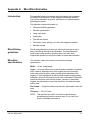
Introduction
The Kodak i7300 Scanner Application Software controls the Kodak
i7300 Scanner and the Kodak Digital Science Intelligent Microimage
Scanner. The scanner is a 16 mm film retrieval subsystem that is
interfaced with a personal computer (PC). The compact film drive and
application software enable:
•
automatic retrieval of images on 16 mm roll microfilm with or without
image marks
•
scanning of the image with a charged coupled device (CCD)
•
image processing and display of the digitally scanned image on the
PC
•
tools to maximize the image quality including editing and annotating
•
delivery of the digital image to the person requesting the image via
standard PC utilities
For the purpose of this manual, the Kodak i7300 Scanner and the Kodak
Digital Science Intelligent Microimage Scanner will be referred to as the
scanner. If something is specific to one scanner or the other, it will be
noted.
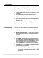
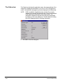
Product features
The Kodak i7300 Scanner Application Software provides the following
features:
•
Easy to use interface — all the tools and procedures you need are
accessible via icons, toolbars, and pull-down menus. A familiar
Microsoft Windows software format also makes it easy to learn.
•
Improved imaging performance — choose Normal or Enhanced
for high-resolution scanning results in a high quality bi-tonal or gray
scale image.
•
Image processing — the powerful algorithms of the application
software deliver high quality images.
•
CAR capability — the application software can be setup to accept
CAR (Computer-Aided Retrieval) commands by adding an optional
Kodak CAR Interface Software to the standard application software.
The CAR 278 Interface, CAR 278 Synchronous Interface Unit or
Hostlink for Micrographics by eiStream Kofile may be required for
interfacing with mainframe computer systems.
•
On-line help the on-line help facility provides access to complete
procedures on how to use the software.
NOTE:
A-61133 March 2003
Even though the i7300 Scanner Application Software works
with the Intelligent Microimage Scanner, the Intelligent
Microimage Scanner will not scan images as fast as the i7300
Scanner, nor can the Intelligent Microimage Scanner do whole
roll conversions.
1-1
System
requirements
See the Installation Planning Guide, A-61405 for software and hardware
requirements.
Using this manual
This User’s Guide describes the functions and procedures of the Kodak
i7300 Scanner Application Software.
Chapters 2, 3 and 4 are directed toward individuals who are responsible
for retrieving images. These individuals must have a working knowledge
of PCs and the Microsoft Windows operating environment. In addition to
computer and retrieval operation skills, a basic understanding of digital
imaging is helpful.
Chapter 5, Setting up CAR Applications, is directed towards users of
systems in which the Kodak CAR Interface Software has been installed.
Chapters 6, 7 and the appendices are intended for the system
administrator who is responsible for configuring and maintaining the
Scanner Application Software.
1-2
A-61133 March 2003
2
Getting Started
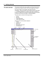
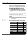
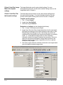
The main window
This chapter describes the menus, toolbars and Control Panel that are
available when using the Kodak i7300 Scanner Application Software.
Some menu options, when selected, will perform the action
immediately. Other menu options, those options followed by three dots
(…), will display a dialog box. If an option on the menu is checked (√),
the option is enabled. More information regarding dialog boxes and how
to use them can be found in Chapter 3, Using the Software.
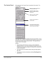
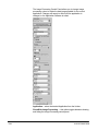
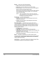
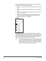
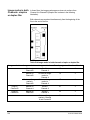
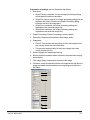
The main window contains the following elements:
• Title bar
• Menu bar
• Image display pane
• Image Retrieval keypad
These elements can be optionally displayed:
• Toolbar
• Control Panel
• Status bar
• Documents/Folder pane
• Thumbnail pane
Title bar
Menu bar
Toolbar
Control Panel
Image Retrieval
keypad
Status bar
A-61133 March 2003
Documents/Folder pane
Thumbnail pane
Image display pane
2-1
The Title bar
The Title bar provides the title of the Scanner Application Software.
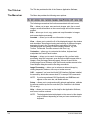
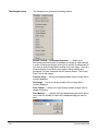
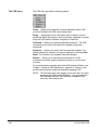
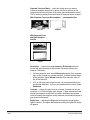
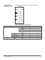
The Menu bar
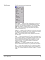
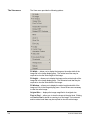
The Menu bar provides the following menu options:
The following summarizes the functions associated with each menu:
File — allows you to open, save and route images, print, fax or e-mail
images, access information on the current image and exit the scanner
session.
Edit — allows you to cut, copy, paste and crop information in images
and access duplex processing.
Annotate — allows you to add new information to images.
View — allows you to control the fit of the displayed image in the window
and orientation. Also allows mirroring and zooming of displayed images,
arranging of icons in the Thumbnail pane, activation of the Image
Retrieval keypad and viewing of various display features, e.g., the
Toolbar, Thumbnails. Provides access to the Error Log.
Customize — allows you to customize the toolbar, keyboard and
manipulate the Control Panel location.
Navigate — allows you to search for images on film, perform batch
processing, stop film movement, scan through multiple images within a
chapter, clear the Image Retrieval keypad, connect to and use the
Kodak Image Server Software, refile the film and provides access to the
Scan Multiple dialog box and the Scrolling commands
Image Processing — allows you to enhance a retrieved image by
utilizing despeckle, deskew, auto-crop or border removal.
CAR appears if you have the Kodak CAR Interface Software installed,
the accessory allows the scanner host PC to accept CAR commands.
NOTE:
If you have purchased CAR functionality and CAR does not
appear on the menu bar, call Kodak service.
Setup — allows you to create and modify retrieval applications, calibrate
the scanner and set up the film controller (Film Controller is for Kodak
FE use only).
Help — allows you to access on-line help for the Application Software,
and current version numbers.
NOTE:
2-2
The keyboard shortcuts displayed on the menus in this chapter
may be different depending on how you have customized your
keyboard.
A-61133 March 2003
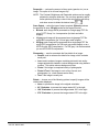
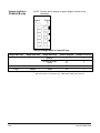
The File menu
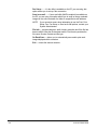
The File menu provides the following options:
Open Image… — displays the Open Image dialog box, which allows
you to open a previously saved image from this application or other
applications. You cannot open multi-page TIFF files, from File>Open
Image. See Chapter 3, Using the Software for more information.
Save — allows you to save an image using the file saving options
specified in Application setup.
Save As… — displays the Save As dialog box, which allows you to save
an image with a user-specified name, format, compression and location.
See Chapter 3, Using the Software for more information.
Close — closes the image that is currently displayed and removes it
from the display.
Print… — if a printer is available on the PC you are using (either local or
via the network), a dialog box will be displayed allowing you to print using
default or modified print options including Print Annotation. The Print
function allows you to print an image, selected images or the entire
contents of a folder. The Print Options dialog box is described in
Chapter 3, “Printing an image”.
Print Setup… — if a printer is available on the PC you are using, a
dialog box will be displayed allowing you to specify default print options.
Fax … — if a fax utility is available on the PC you are using, this option
allows you to fax an image, selected images or the entire contents of a
folder. The Fax Options dialog box is described in Chapter 3, “Faxing an
image”.
A-61133 March 2003
2-3
Fax Setup… — if a fax utility is available on the PC you are using, this
option allows you to set up a fax connection.
Send as e-mail… — if an e-mail utility (MAPI-compliant) is available on
the PC you are using, this option allows you to send an image, selected
images or the entire contents of a folder to a specified e-mail address.
NOTE:
If you encounter errors when attempting to use the Print, Print
Setup, Fax, Fax Setup, or Send as e-mail options, contact your
System Administrator.
File Info — provides bits/pixel, width, height, resolution and if the file has
been modified. After the file has been saved, File Info also provides the
file name, file size, file date and file type.
On Each Scan — allows you to automatically save and/or print each
image displayed within a session.
Exit — closes the scanner session.
2-4
A-61133 March 2003
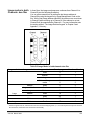
The Edit menu
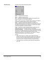
The Edit menu provides the following options:
Undo — cancels the last edit action.
Redo — repeats the last edit action.
Cut — removes the selected image or portion of an image from the
display and places it on the Windows clipboard.
Copy — allows you to copy a complete image or portion of an image to
the Windows clipboard without removing it from the display.
Paste — copies any image content data that is currently on the
Windows clipboard into the current image. The image data you copy will
be pasted in the upper left corner of the image. Use the mouse cursor
to drag the image data to the desired location.
Crop — allows you to draw a rectangle around a specific area of an
image and discard any information outside of the rectangle.
Duplex Processing… provides the option of arranging the front and
back sides of an image from duplex film vertically rather than horizontally
(side by side). Duplex processing is generally used for check
applications with duplex or duo duplex film. See Chapter 3, Using the
Software for procedures on how to use this function.
NOTES:
A-61133 March 2003
•
After using the Undo, Cut, Paste, Crop or Duplex Processing
functions, no further image processing changes can be made from
the Control Panel. Use these functions after all image processing
changes are made, but before Annotating, Saving and Printing.
•
The Control Panel is not effective when viewing an image opened
from a file.
2-5
The Annotate menu
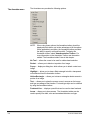
The Annotate menu provides the following options:
NOTE:
When using these options, the Annotation toolbox should be
displayed which allows you to take advantage of all the options.
When applicable to an option, the Annotation toolbox provides
the ability to specify color and line width. To display the
Annotation toolbox, select View>Annotation Toolbox. For
more information on the Annotation Toolbox see the section
entitled “The Annotation toolbox” later in this chapter.
No Tool allows the cursor to be used for rubber-band selection.
Redact allows you to blank out a portion of an image.
Popup displays a dialog box, which allows you to attach a note to an
image.
Highlight — allows you to draw a filled rectangle but with a transparent
color selected from the Annotation toolbox.
Hollow Rectangle — allows you to draw a rectangular border around a
portion of an image.
Text — allows you to place the mouse cursor in an area on the image
and type a message at that location. Font and type style can be selected
by using the Annotation toolbox.
Freehand Line displays a pencil that can be used to draw freehand.
Arrow allows you to draw arrows. The Annotation toolbox can be
used to specify line width, color and arrowhead direction and type.
2-6
A-61133 March 2003
Select allows you to edit previously created text, move and/or resize
previously created arrows, boxes, etc.
Image displays the Open dialog box, which allows you to select a
Windows bitmap image to overlay on the currently displayed image
(e.g., Approved, Paid, Canceled, etc), like a rubber stamp.
Polyline allows you to draw a series of line segments by connecting
points.
Load Image… displays the Load Image dialog box, which allows you
to load a different image file into memory. See Chapter 3, Using the
Software for more information.
Canned — allows you to save annotation created for an image, for use
on other images. See Chapter 3, Using the Software for more
information.
A-61133 March 2003
2-7
The View menu
The View menu provides the following options:
Fit Width — allows you to display the image so the entire width of the
image fits in the Image display pane. The vertical scroll bar may be
required to view the entire length of the image.
Fit Height — allows you to display the image so the entire length of the
image fits in the Image display pane. The horizontal scroll bar may be
required to view the entire width of the image.
Fit Window — allows you to display the entire length and width of the
image so it fits in the Image display pane. No scroll bars are necessary
to view the entire image.
Original Size — displays the image magnified to its original size.
Pixel to Pixel allows you to view the image at the pixel level. Clicking
on Pixel to Pixel is similar to zooming in on an image. The horizontal
and/or vertical scroll bars may be required to view the entire image.
2-8
A-61133 March 2003
Rotated 90° Clockwise — allows you to rotate an image 90 degrees to
the right (clockwise). Rotation is based upon the original displayed
position of the image.
Rotated 180° — allows you to rotate an image 180 degrees. Rotation is
based upon the original displayed position of the image.
Rotated 270° Clockwise — allows you to rotate an image 270 degrees
to the right (clockwise). Rotation is based upon the original displayed
position of the image.
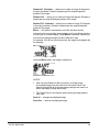
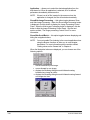
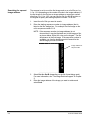
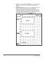
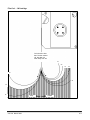
Mirror — this option is used when a roll of film has been wound
incorrectly on the reel and the image appears as if it was being viewed in
a mirror and is “reverse-reading”. When Mirror is selected, it allows you
to reverse the displayed image to make it read left to right.
For example, if the film is wound incorrectly, the image would appear like
the following:
Using the Mirror option, the image is changed to:
NOTES:
•
After using the Rotated or Mirror functions, no further image
processing changes can be made from the Control Panel. Use
these functions after all image processing changes are made, but
before Annotating, Saving and Printing.
•
The Control Panel is not effective when viewing an image opened
from a file.
Zoom In — enlarges the displayed image.
Zoom Out — reduces the displayed image.
A-61133 March 2003
2-9
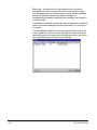
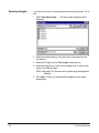
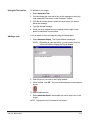
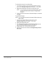
Error Log displays the Error Log dialog box which shows the
messages and errors that occurred for the current scanner session.
The messages posted in the Error Log are normal system messages
and can be both informational and critical messages. For
troubleshooting information regarding these messages, see Chapter 6,
Troubleshooting.
The dialog box is cleared automatically when the application software is
exited. Errors and messages are saved permanently in an error log on
the system.
You can change the width of the columns by placing the cursor on the
column divider line. When the cursor changes to a horizontal size bar,
press and hold the left mouse button and drag the cursor to the right or
left until the desired size of the column is achieved.
2-10
A-61133 March 2003
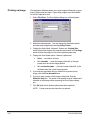
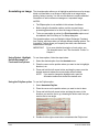
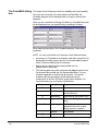
Viewing or hiding View
menu options
You can view or hide the following features using the View menu:
•
•
•
•
•
•
Toolbar
Control Panel
Annotation Toolbox
Status bar
Documents/Folder pane
Thumbnails pane
When a check mark is displayed next to the menu option (as shown
below), the feature will be visible and active.
NOTE:
If you want Thumbnails displayed, you need to select
Thumbnails and the way in which you want it displayed (i.e.
Small Icons, Large Icons, etc.) every time you open the
application.
To hide a feature:
•
Click on the menu option to deselect it. The check mark will
disappear from the menu and the feature will disappear from the PC
display.
Arrange Icons the icons in the Thumbnail pane can be arranged by
name, type, size or date.
Refresh — refreshes the Document/Folder pane and Thumbnails if
displayed.
Keypad — allows you to activate the Image Retrieval keypad.
NOTE:
A-61133 March 2003
Assigning a shortcut key to the Keypad function will increase
productivity.
2-11
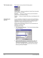
The Customize menu
The Customize menu provides the following options:
Control Panel allows you to position the Control Panel to the right or
left of the window, or to hide it.
Keyboard… — allows you to assign commonly used commands to
function keys or a combination of keys.
Toolbar… — allows you to specify what tools you want displayed on the
toolbar.
Customizing your
keyboard
You can customize your keyboard so you can work more efficiently by
assigning shortcut keys or setting up a pattern of keystrokes instead of
choosing menu items or toolbar functions. The following procedure
explains how to assign and unassign shortcut keys.
Kodak provides default keyboard shortcuts, for more information see
Appendix D, Productivity Tools.
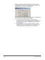
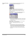
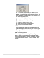
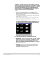
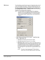
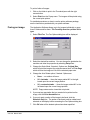
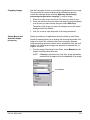
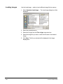
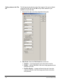
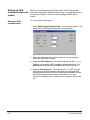
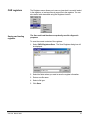
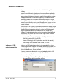
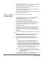
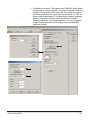
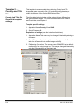
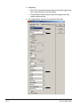
Assigning shortcut keys
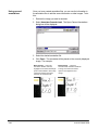
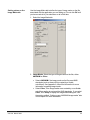
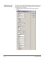
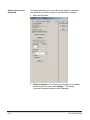
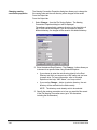
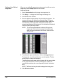
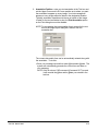
1. Select Customize>Keyboard… The Customize Keyboard dialog
box will be displayed:
2. The list in the Menu Entries box corresponds with the Menu bar.
Shortcuts can be assigned only at the lowest menu level, e.g.,
File>On Each Scan>Auto Save. To move quickly to a first-level
menu choice, select File, then type the first letter of the desired
choice (e.g., N to go to Navigate).
2-12
A-61133 March 2003
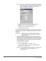
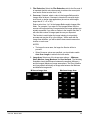
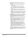
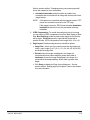
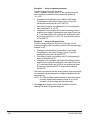
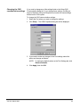
3. Place the cursor in the New Shortcut field and enter the desired
shortcut. Valid entries include any individual alphanumeric character
or function key used in conjunction with the Ctrl+Alt or Ctrl keys. The
function keys can also be used alone. Examples of valid shortcuts:
Ctrl+Alt+S, Ctrl+F11, F8, Shift+F2.
NOTES:
•
When you assign a shortcut key, do not assign F1 or F10, and
be sure the shortcut key is not assigned to another function.
•
The Alt key cannot be used alone when you are assigning
shortcut keys. You must use Ctrl with the Alt key (i.e., Ctrl+Alt).
•
If you want multiple PCs to be set up with the same shortcut key
assignments, contact Kodak service.
4. Click Assign.
5. Assign any other shortcut keys desired using Steps 2 through 4.
6. When finished, click OK.
A-61133 March 2003
2-13
Unassigning shortcut keys
1. Select the desired menu item from the Menu Entries list box.
2. If None is displayed in the New Shortcut field, click Assign. If a
shortcut is displayed in the New Shortcut field, place the cursor in
the New Shortcut field and click Assign. Press the spacebar. None
will be displayed in the New Shortcut field.
3. Unassign any other shortcut keys as desired.
4. When finished, click OK.
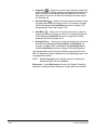
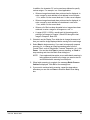
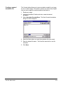
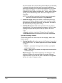
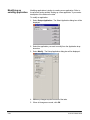
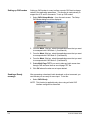
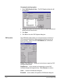
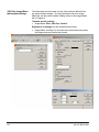
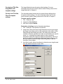
Customizing the toolbar
You can customize the toolbar to display only the toolbar buttons you
want to use. To do this:
•
Select Customize>Toolbar… The Customize Toolbar dialog box
will be displayed:
To add buttons to the toolbar:
1. Select the button that you would like to add to the toolbar from the
Available Buttons list box.
2. Click Add. The button you selected will be added to the toolbar.
3. Add as many buttons as desired.
4. When finished, click OK.
To remove buttons from the toolbar:
1. Select the button you want to remove from the toolbar from the
Toolbar Buttons list box.
2. Click Remove. The button you selected will be removed from the
toolbar.
3. Remove as many buttons as desired.
4. When finished, click Close.
2-14
A-61133 March 2003
To rearrange buttons on the toolbar:
1. Select the button to be moved on the Toolbar Buttons list box.
2. Click on the Move Up or Move Down button.
3. Move as many buttons as desired.
4. When finished, click Close.
The button at the top of the Toolbar Buttons list box will be the first
button on the left if the toolbar is in the horizontal position.
NOTE:
A-61133 March 2003
At any time, you can select Apply to preview the changes on
the toolbar or Reset to return to the default toolbar.
2-15
The Navigate menu
The Navigate menu provides the following options:
Browse Forward… and Browse Backward… — allows you to
automatically browse forward or backward one image at a time through
a series of contiguous images, pausing for a number of milliseconds (of
your choice) at each image before moving to the next image. There is a
minimum display time while the next image is being scanned and
processed. For more information see the section entitled, “The Control
Panel” later in this chapter.
Previous Image — moves one image backward from the image that is
currently displayed.
Next Image — moves one image forward from the image that is
currently displayed.
Scan Chapter — allows you to scan through multiple images within a
chapter for printing.
Scan Multiple…. — displays the Scan Multiple dialog box which allows
you to enter the number of copies of the displayed image you want to
print.
2-16
A-61133 March 2003
Batch Scan… — scans a specified group of images, which do not have
to be contiguous or continuous. The images must be automatically
saved to a directory and/or printed. See the section entitled, “Batch
scan” in Chapter 3 for more information.
Clear used to clear information from the Image Retrieval keypad text
box, and stop any film movement (i.e., searching, refiling, etc.).
Set A when used with the number keys, allows you to preset the
starting image address for Channel A or change the current Channel A
image address.
Set B when used with the number keys, Set B allows you to preset
the starting image address for Channel B, preset the last image address
for Channel B (duo film), or change the current Channel B image
address.
Refile Film — when selected, rewinds the film currently in the scanner.
When completed, the film magazine can be safely removed.
Search Again when the image found by a search is not readable
(e.g., there was a jam or other error during filming) and you know that
the image was filmed again with the same image address elsewhere on
the film, Search Again allows you to search for the next occurrence of
the image address on the film. Search Again is also useful when related
images on the roll have the same image address. Search Again is used
in conjunction with Random Batch Code.
Image Server allows you to connect to the Image Server
Dispatchers and Image Server Software. In addition you can send
scanned images to the Image Server Software, so that individual images
or a folder of images can be printed, faxed, or emailed. For more
information, see Chapter 7, Network Operations.
Scroll provides a drop-down list of speed and directions to scroll the
film from the current position (i.e., Fast Forward, Fast Backward, Slow
Forward, etc.). Once the direction is selected, the images will be
viewed in the Scrolling window while the film is moving. The Scrolling in
Progress dialog box is displayed during scrolling. When the desired
image is displayed, click Stop or Process in the dialog box. Select
Process to prepare the image for printing, faxing, emailing or saving.
NOTES:
•
•
•
A-61133 March 2003
Selecting Stop will exit the Scrolling function.
The image address displayed on the Status bar may not match the
image displayed on the screen.
During scrolling you can use the Zoom functionality to enlarge (by
rubber-banding and right-mouse clicking the area you want to zoom
in on) or reduce (right-mouse click) the image for easier viewing.
2-17
Pause – momentarily stops the film at the selected image until you
select Resume . When you select Resume , scrolling will begin at the
image where it left off when Pause was selected.
How you process your image is dependent upon how your application is
set up. One of the following methods is available:
•
•
2-18
If your application is set up for Manual or Automatic Duplex
Processing, the Duplex Processing dialog box will be displayed. For
more information see Chapter 3, “Setting Manual and Automatic
duplex processing”.
If your application is not set up for duplex processing, the Select
Overscan dialog box will be displayed. For more information see
“The Image Processing Control Panel” later in this chapter.
A-61133 March 2003
The Image Processing
menu
The Image Processing menu provides the following options for the
currently displayed image (bi-tonal images only):
Despeckle — reduces the amount of noise and specks, etc.
Successive use of the menu will cycle through the values of 0, 1, 2.
Deskew — automatically straightens the displayed image using a
default deskew amount.
Manual Deskew… — displays the Manual Deskew dialog box, from
which the image can be deskewed by a specified amount.
•
Enter the amount of the angle to rotate the image. A positive number
will rotate clockwise. A negative number will rotate counterclockwise.
•
Click OK when finished.
Border Remove — removes the borders from around the scanned
image, but maintains the physical image size.
Auto Crop automatically discards the border of an image.
NOTES:
A-61133 March 2003
•
After using the Undo, Cut, Paste, Crop or Duplex Processing
functions, no further image processing changes can be made from
the Control Panel. Use these functions after all image processing
changes are made, but before Annotating, Saving and Printing.
•
The Control Panel is not effective when viewing an image opened
from a file.
2-19
The CAR menu
The CAR menu provides the following options:
Setup allows you to associate a retrieval application with a CAR
mode and configure the CAR communication port.
Ready signals back to the CAR system that it is ready to receive
downloads, batch downloads or direct commands. Applicable only when
using the CAR Interface Software configured as listen-talk.
Download — allows you to perform download operations. The CAR
commands do not need to be loaded into registers during these
downloads.
Registers — allows you to save, load, view and clear registers. You
can also display the contents of a range of registers by selecting Start
Batch. The contents of the registers cannot be changed.
Monitor allows you to stop and resume execution of CAR
commands to perform image processing functions or use the menu
functions.
For more information regarding the Kodak CAR Interface Software, see
Chapter 5, Setting up CAR Applications. Appendix C, Glossary, also
provides some common terms and definitions regarding CAR.
NOTE: The CAR menu item only appears on the menu bar if you have
purchased the CAR Interface Software. If you purchased the
CAR Interface Software, and CAR does not appear on the
menu bar, call Kodak service.
2-20
A-61133 March 2003
The Setup menu
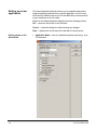
The Setup menu provides the following options:
Application… — displays the Select Application dialog box, which
provides access to create a new application(s) and modify or delete an
existing application(s). See Chapter 4, Application Setup for more
information.
Film Controller… this option is for Kodak Field Engineer use
only and should not be changed. Film Controller allows the selection
of the COM port the scanner and the PC running the Scanner
Application Software are attached to. The Film Controller dialog box also
displays the scanner firmware version, thread-up attempts and
successful scans.
Calibration… — displays the Calibrate dialog box, which allows you to
calibrate the scanner. Calibration typically takes less than 15 seconds to
complete and should be done each time the scanner is turned on.
NOTE: Do not attempt to thread film during Calibration.
For more information regarding calibration, see Chapter 3, Using the
Software.
A-61133 March 2003
2-21
The Help menu
The Help menu provides the following options:
i7300 Scanner Help — displays the contents of the Application
Software on-line help topics, including menus, procedures, glossary
terms and messages.
Contents and Index — displays the Help Topics dialog box. The Index
tab provides an alphabetic listing of information associated with the
Application Software. You can enter the word or string of words you
want information about in the text edit field. The Find tab allows you to
search for specific words and phrases in the Help topics.
About… — displays a window containing software copyright and
version information.
2-22
A-61133 March 2003
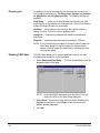
The Toolbar
If the toolbar is not displayed, it can be displayed by choosing
View>Toolbar. Procedures on how to use these functions are included
in this section or Chapter 3, Using the Software. Most of these options
can also be accessed from the menus.
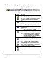
The following table provides the toolbar options and a brief summary of
their function:
Button
Description
Open Image — allows you to open an image
previously saved to a file.
Save —saves the image to the root directory and with
the file naming convention specified in Application
setup.
Print — allows you to print the displayed image to the
default printer.
NOTE: Print capability is a customer-supplied utility to
the PC. It is not provided by Kodak.
Fax — allows you to fax the displayed image to the
default fax machine.
NOTE: Fax capability is a customer-supplied utility to
the PC. It is not provided by Kodak.
E-mail — allows you to e-mail the displayed image.
When selected, a Send To dialog box will be displayed.
NOTE: E-mail capability is a customer-supplied utility
to the PC. It is not provided by Kodak. When
using web-based “free” E-mail services, you
must manually attach the images.
Cut removes the selected image or portion of an
image from the display and places it on the Windows
clipboard.
Copy allows you to copy a complete image or
portion of an image to the Windows clipboard without
removing it from the display.
Paste — copies any image data that is currently on the
Windows clipboard into the current image.
Undo — cancels the last edit action.
Redo — repeats the last edit action.
A-61133 March 2003
2-23
Button
Description
Zoom In — allows you to enlarge the image on the
display.
Zoom Out — allows you to reduce the image on the
display.
Fit Width — resizes the image so the entire width of
the image fits in the Image display pane.
Fit Window — resizes the image so the entire length
and width of the image fits in the Image display pane.
Rotate 90° Counterclockwise — rotates the
displayed image 90 degrees to the left based upon the
current image position.
Rotate 90° Clockwise — rotates the displayed image
90 degrees to the right based upon the current image
position.
Minus moves the film backward one image.
Plus moves the film forward one image.
To execute the command corresponding to a specific tool:
•
Click on the toolbar button.
NOTE:
2-24
If a tool is grayed, it is not available at that moment.
A-61133 March 2003
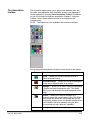
The Annotation
toolbox
The Annotation toolbox allows you to specify font attributes, color and
line width, when applicable. If the Annotation toolbox is not displayed, it
can be displayed by choosing View>Annotation Toolbox. Procedures
on how to use these functions are described in Chapter 3, Using the
Software. Most of these options can also be accessed from the
Annotate menu.
NOTE:
The Ellipse tool is not available in this release of software.
The following table describes the function of each button on the toolbox.
Button
Description
Arrow allows you to draw a straight line with or
without an arrow head(s).
Hollow Rectangle — allows you to draw a rectangular
border around a specific area on an image.
Highlight — allows you to draw a rectangle highlighting
a specific area with a transparent color. This option
allows you to call attention to something specific on an
image.
Redact — allows you to draw a rectangle on a
displayed image with a solid, opaque color. This allows
you to mask over some part of the image that you do
not want the recipient to see, but lets the recipient know
that information has been masked. Using the white
color provides you with “white-out” capability.
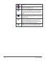
Button
A-61133 March 2003
Description
2-25
Freehand Line allows you to draw free-form lines.
Polyline allows you to draw a series of line
segments by connecting points.
Text — allows you to type a text message to be added
to the image. Click on Fonts to allow you to select the
font type, size and style for the text. This font selection
will remain active until you change it or the software is
exited.
Image displays the Open dialog box, which allows
you to select a bitmap image to attach to the currently
displayed image.
Popup select this tool, then click with the left mouse
button in the Image display pane to display the Popup
dialog box which allows you to attach a note to an
image. This note will appear as an icon on the image
alerting the recipient that a note is attached.
Select allows you to select any previously created
annotations so it can be moved, resized or deleted.
2-26
A-61133 March 2003
The Image Retrieval
keypad
The Image Retrieval keypad is usually displayed at the bottom of the PC
monitor. This keypad can be placed anywhere on the screen.
To move the Image Retrieval keypad:
• Place the mouse cursor on the title bar of the keypad, press and
hold the left mouse button and drag the keypad to the desired
location.
The following buttons on the Image Retrieval keypad are mapped to the
keyboard’s keypad:
•
•
•
•
Numeric keys to the number keys
Srch to the Enter key
+ button to the + key
- button to the - key
NOTES:
•
The Num Lock, *, /, and Delete keys on the PC keyboard do not
map to Clr, Set A, Set B and Refile on the keypad.
•
To use the numeric keys on your PC, be sure that Num Lock is
active on the keyboard.
You can activate the keypad either by clicking on it or selecting
View>Keypad from the Menu bar. When the keypad is active, you can
use the mouse to select from the keypad, or use the physical keypad on
the keyboard.
NOTE:
Assigning a shortcut key to the Keypad function can increase
productivity.
Following is a description of the fields on the Image Retrieval keypad.
Image Retrieval text box — enter the desired image address in the
text entry box.
Full Keypad — this keypad can be displayed in full or partially. When
this option is checked, the full keypad will be displayed.
Full Keypad
Partial Keypad
Image
Retrieval
text box
A-61133 March 2003
2-27
Clr (Clear)—the Clr button is used to clear information from the Image
Retrieval keypad text box. When Clr is selected, it will also stop any film
movement (i.e. searching, refiling, etc.)
Set A — when used with the number keys, allows you to:
• preset the starting image address for Channel A (e.g., film roll #2
continues from roll #1, and starts with image address 20.0) or,
• change the current Channel A image address (e.g., to correct for
errors in filming).
Enter the desired preset address then click on the Set A button.
Set B — when used with the number keys, allows you to:
• preset the starting image address for Channel B (e.g., 3890 check
film from a camera sorter) or,
• preset the last image address for Channel B, (e.g., with duo film,
Channel A and Channel B can then be searched simultaneously to
save time) or,
• change the current Channel B image address (e.g., to correct for
errors in filming).
Enter the desired preset address then click on the Set B button.
Refile — when finished with the film currently in the scanner, select
Refile to rewind the film.
Numeric buttons — used to enter an image address. The numeric
buttons (in conjunction with the + and – buttons) can also be used to
specify the number of images to go forward or backward. For example,
enter 10, then select the + key; the film will be advanced 10 images.
Srch (Search) — after entering an image address, click Srch (or press
Enter) to locate the image.
- (minus) moves the film backward one image at a time.
+ (plus) moves the film forward one image at a time.
NOTE:
When using the – or + keys, it is not necessary to select Srch
or press Enter. Doing this could cause a Controller Timeout
error message.
. (decimal) used for multi-level film image addressing (e.g., 15.0 for 2level or 22.5.0 for 3-level).
NOTE:
2-28
Num Lock on the keypad of the PC keyboard must be On for
the numeric buttons to function properly.
A-61133 March 2003
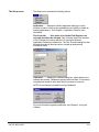
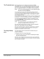
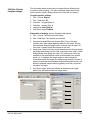
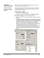
The Control Panel
All functionality of the Control Panel is described in this section. The
Control Panel:
Allows you to select an application
from the drop-down box.
Provides the ability to hide or
display the Image Processing
control panel.
Allows you to hide or display
the Scroll/Batch buttons.
Provides a status update via
the status field.
The Image Retrieval keypad is
not part of the control panel and
can be moved to any location.
The Image Retrieval keypad is separate from the Control Panel, can be
displayed in full or partially, and can be moved anywhere on your screen.
For more information, see the section entitled, “The Image Retrieval
keypad” earlier in this chapter.
NOTES:
A-61133 March 2003
•
The last image retrieved stays in memory until the Application
Software is closed. If you close the displayed image, then use the
Control Panel to make any changes, the image will be automatically
recalled and displayed.
•
The Control Panel is not effective when viewing an image opened
from a file.
•
The keypad can also be activated by selecting View>Keypad from
the Menu bar.
2-29
Application allows you to select the desired application from the
drop-down list. When an application is selected, all of its defined
parameters immediately become active.
NOTE:
If there is a roll of film inserted in the scanner when the
application is changed, the film will rewind automatically.
Show/Hide Image Processing — this option toggles between Show
and Hide Image Processing. When the Show Image Processing button
is displayed, click this button to display the Image Processing Control
Panel. When the Hide Image Processing button is displayed, click the
button to hide the Image Processing Control Panel. See the next
section entitled, “The image processing Control Panel” for more
information.
Show/Hide Scroll/Batch — this option toggles between displaying and
hiding the navigation buttons.
NOTE:
You must enable Plus Indexing in the current application when
using the Browse functions to allow you to cross chapter
boundaries. For more information see the section entitled,
“Setting values on the General tab” in Chapter 4.
When the Navigation buttons are displayed, you can choose one of the
following options:
- moves backward by one image.
+ moves forward by one image.
<:: displays the Browsing dialog box and initiates browsing
backward one image at a time.
::> displays the Browsing dialog box and initiates browsing forward
one image at a time.
2-30
A-61133 March 2003
The Browsing dialog box allows you to pause browsing, specify
display time for each image in milliseconds, and change to
browsing in the other direction. While paused, image processing
changes may be made using the Image Processing Control
Panel.
•
To end browsing, click Close.
•
The
button suspends the browsing function. To resume
browsing click on the
button. The right or left arrows can
•
<<
<
>
>>
be used to go forward or backward . It is not necessary to
suspend browsing when changing direction.
Use the Display Time slider bar to change the amount of time
you want the image displayed before moving to the next
image.
moves the film rapidly backward.
moves the film slowly backward.
moves the film slowly forward.
moves the film rapidly forward.
NOTE: Images will not be displayed while using these functions.
Film movement will not show in the Image display pane. To move
the film, place the mouse cursor on the desired button and press
and hold the left mouse button. Release the left mouse button to
stop the scanner transport and scan a section of film.
Batch — displays the Batch Scan dialog box, which allows a
selected set of images to be scanned and saved and/or printed. See
the section entitled, “Batch scan” in Chapter 3 for more information.
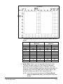
Scrolling buttons the scrolling buttons allow you to scroll the film
at varying speeds forward or backward. The speed at which the film
moves is different based on the resolution (Normal or Enhanced).
Resolution
Fast Speed
Medium Speed
Slow Speed
Normal
12.4 mm/second
6.2 mm/second
3.1 mm/second
Enhanced
6.2 mm/second
3.1 mm/second
1.55 mm/second
You can scroll in either (Scan Output) bi-tonal or grayscale (16-gray
or 256-gray). Scrolling defaults to 256-gray levels (unless it is
changed in Application Setup).
A-61133 March 2003
2-31
<< moves the film rapidly backward, then resume scrolling.
< moves the film slowly backward, then resume scrolling.
Pause momentarily stops the film at the selected image until you
select Resume . Film will be repositioned to scroll where you left off.
> moves the film slowly forward.
>> moves the film rapidly forward.
((( scrolls the film backward at the fast speed
(( scrolls the film backward at the medium speed
( scrolls the film backward at the slow speed
) scrolls the film forward at the slow speed
)) scrolls the film forward at the medium speed
))) scrolls the film forward at the fast speed
NOTES:
•
•
During scrolling you can use the Zoom functionality to enlarge (by
rubber-banding and right-mouse clicking the area you want to zoom
in on) or reduce (right-mouse click) the image for easier viewing.
The image address displayed on the status bar may not match the
image displayed on the screen.
Stop — exits the Scrolling function.
Process — prepares the image for printing, faxing, emailing or saving.
Status — displays the image address of the current image and any
status messages associated with the image. For example, messages
such as, Searching, Refiling, Scanning, Image not Found, etc. will be
displayed.
2-32
A-61133 March 2003
The image processing
Control Panel
Image processing parameters are setup via the Setup>Application
function at the time of installation or by the system administrator. You
can temporarily override the original values for an application. The
Application Software provides two levels of overriding image processing
parameters.
•
•
Use the Image Processing menu to temporarily override image
processing parameters for the currently displayed image. For more
information see the section entitled, “The Image Processing menu”
in this chapter.
Use the Image Processing Control Panel to temporarily override
image processing parameters for the current retrieval application.
If the Control Panel is not visible, select View>Control Panel from the
menu. The Control Panel will be displayed. Once the Control Panel is
visible, you can hide or display the Image Processing portion of the
Control Panel. You may choose to hide the entire Control Panel at any
time to provide a larger Image display pane.
A-61133 March 2003
2-33
The Image Processing Control Panel allows you to change image
processing values to obtain the best image possible for the current
application. Changes will remain in effect until the application is
changed, or the Application Software is exited.
Application— select the desired Application from the list box.
Show/Hide Image Processing — this option toggles between showing
and hiding the Image Processing control panel.
2-34
A-61133 March 2003
Scan Area determines the area of the film that the image processing
settings are applied to.
•
Primary image processing settings are applied to the entire
image area that is defined in the Application Setup. This is the only
option available for non-duplex processing.
Front and Back are available when Duplex Processing is enabled.
• Front image processing settings are applied to only the front side
of the image.
• Back image processing settings are applied to only the back side
of the image.
Duplex Processing provides the option of arranging the front and
back sides of an image from duplex film vertically rather than
horizontally.
•
•
None disables Duplex Processing.
Manual to initially define the front and back areas. When Manual
is selected, the image area defined in Application Setup will be
displayed in the Duplex Processing dialog box.
•
Automatic uses the last specified manual setting to automatically
display all images in duplex processing view. This is useful when all
images on the film are the same size.
For procedures on using Duplex Processing, see the section entitled,
“Setting Manual and Automatic duplex processing” in Chapter 3.
A-61133 March 2003
2-35
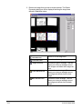
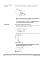
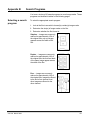
Separate Front and Back check this option when you want to
create two separate image files or prints; one file for the front of the
image and one file for the back of the image (see the illustration below).
This is useful for printing fronts and backs on separate sheets of paper.
With Separate Front and Back enabled two separate files
100F.tif
100B.tif
With Separate Front
and Back disabled
one file
100.tif
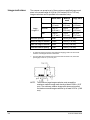
Resolution — choose from either Normal or Enhanced resolution.
Normal will scan the image at 3650 pixels; Enhanced will scan the
image at 7300 pixels.
•
If bi-tonal output is used, select Enhanced resolution if the reduction
ratio on film is equal to or greater than 40X, to obtain the best image
quality possible. Select Normal resolution if the reduction ratio on
film is less than 40X.
•
If 16- or 256-gray scale output is used, it is recommended that you
use Normal resolution. If you are not satisfied with the result, select
Enhanced.
Contrast — adjusts the gray levels in an image. Contrast can only be
used with 16- or 256-level gray scale images. A high contrast value will
display the image as mostly black and white, whereas a low contrast
value will display the image as mostly midtones (more subtle changes in
gray levels are detected).
Brightness — adjusting the Brightness will make the image appear
lighter or darker. The higher the Brightness setting the lighter the image
will appear.
2-36
A-61133 March 2003
Despeckle — reduces the amount of stray spots (specks, etc.) on an
image. This option is for bi-tonal images only.
NOTE: The Contrast, Brightness and Despeckle options can be roughly
adjusted by using the slider bar. You can more precisely adjust
these options by entering a value in the entry field or use the up
and down arrows to obtain the desired value
.
Scan Output — select the type of output required. (Bitonal produces
the smallest file size; 256-gray produces the largest file size).
•
Bi-tonal: each image will be processed as a single-page TIFF file
using CCITT Group 3 or 4 compression (for black and white
images).
16 gray: each image will be processed as a single-page TIFF file
using JBIG compression (for 16-level gray scale images).
256 gray: each image will be processed as a single-page TIFF file
using JPEG compression (for 256-level gray scale images) or as a
JPEG file with JPEG compression. For 256 gray, it is recommended
you use JPEG/JPEG compression.
•
•
Sharpening — used to accentuate the fine details of an image.
•
•
•
•
•
Normal: used to enhance the detail of an image, which contains
small print.
Low: used to enhance images containing dot matrix text and/or
images printed with shaded or colored backgrounds using halftone
screens. This option reduces background noise.
Photo: if the image is comprised mainly of photographs.
Photo & Text: if the image is a mix of text, line art, and
photographs (i.e., check camera-sorter films).
Text: if the image is mostly text.
Rotate — choose one of the following options to specify images will be
rotated when displayed:
• None: to process the image in the original orientation.
• 90° Clockwise: to process the image rotated 90° to the right.
• 180° Clockwise: to process the image rotated 180° to the right.
• 270° Clockwise: to process the image rotated 270° to the right.
A-61133 March 2003
2-37
Border — choose one of the following options:
•
•
•
Leave: keeps the border around the image.
Auto crop: removes the border from around the image.
Border remove: removes the border from around the image but
does not reduce the scanned image file size.
Border remove works best with images that have proper exposure
and a reasonable space between images. Do not use Border
remove with light images.
NOTE: When using Border remove or Auto crop, the entire
image (all borders) must be visible in the image area so
the image can be properly processed.
Film Polarity — select the following option:
•
•
Negative: if the film image is a black background and a clear
foreground/character(s).
Positive: if the film image is a clear background and a black
foreground/character(s).
Film Image Quality used with bi-tonal or gray scale output to
improve readability of images from a film that is too light or too dark. It
can also improve low contrast images. This feature widens the range
between the lightest and darkest pixel in the image. Select one of the
following options if desired:
•
•
•
•
No Adjustment: no enhancement.
Light Film: if film is light, it makes the dark areas darker.
Normal Film: if film has the correct exposure but low contrast, this
option adds contrast to the image.
Dark Film: if the film is dark, it lightens the background and other
areas that should be lighter.
Mirror — this option is used when a roll of film has been wound
incorrectly on the reel and the image appears as if it were being viewed
in a mirror and is “reverse-reading”. Check this option if you want the
image to appear right-reading.
Auto Deskew — automatically straightens the displayed image. When
Auto Deskew is enabled, Auto crop will also be enabled.
2-38
A-61133 March 2003
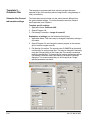
Overscan to enable or disable scanning and display of a specified
number of images before and after the image you requested. The Before
and After values are defined in Application setup. Overscan is useful for
film with poor image alignment within the film frame, such as 3890
single-level check film. When Overscan is checked, the images will
initially be displayed in the Select Overscan dialog box.
NOTES:
•
•
•
•
When using the scrolling function, it is not necessary to have
Overscan specified in Application Setup or enabled on the Image
Processing Control Panel.
The image address displayed on the status bar may not match the
image displayed on the screen.
If Duplex Processing is enabled, the Duplex Processing dialog box
will be displayed instead. For procedures on using duplex
processing, see the section entitled “Setting manual and automatic
duplex processing” in Chapter 3.
The dialog box displayed below may appear differently based upon
the options selected on the Page Layout dialog box (Output tab).
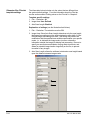
The Select Overscan dialog box contains several tool buttons.
♦ Selection
allows you to move the Image Area green rectangle
by placing the cursor inside the rectangle, pressing the left mouse
button, and dragging the rectangle to the desired location. Also
allows you to resize the rectangle using the handles, or zoom from a
point of origin outside the rectangle by drag-selecting and clicking
with the right mouse button.
♦ Zoom
allows you to zoom from a point of origin inside or
outside the Image Area green rectangle by drag-selecting and
clicking with the right mouse button.
A-61133 March 2003
2-39
♦ Image Area
allows you to remove and redraw the Image Area
green rectangle by clicking outside the rectangle with the left mouse
button to remove, then drag-selecting the desired area to redraw.
Also allows you to move or resize the rectangle, the same way as
the Selection tool.
♦ Previous Block
allows you to decrement and scan by a block
of images rather than one image at a time. For example, if images
48-52 are displayed, Previous Block will result in images 43-47
being displayed, rather than images 47-51.
♦ Next Block
allows you to increment and scan by a block of
images rather than one image at a time. For example, if images 4852 are displayed, Next Block will result in images 53-57 being
displayed, rather than images 49-53.
♦ Overlap By One allows you to retain one image from the current
block when navigating with Previous Block or Next Block. For
example, if images 48-52 are displayed, and Overlap By One is
enabled, Next Block will result in images 52-56 being displayed.
Use the appropriate tools to select the desired image area then click
OK. The selected area will be displayed in the Image display pane in the
main application window.
NOTE:
Enable Overscan prior to starting a search, otherwise the
Reprocess button will be unavailable.
Reprocess — select Reprocess to return to the Duplex Processing
dialog box or Select Overscan dialog box if those options are enabled.
2-40
A-61133 March 2003
The Thumbnail pane
The Thumbnail pane can be displayed by selecting the View>
Thumbnails option. You can display thumbnails as small icons, large
icons, a list, or a list with details. Select None to hide the Thumbnail
pane. The Application Software is only capable of opening image files.
NOTE:
If you want Thumbnails displayed, you must enable this option
each time you open the application.
You can select one or more of the thumbnails by clicking the right
mouse button which will display a popup menu that allows you to open,
cut, copy, paste, delete, rename, fax, print, e-mail images or create or
email multi-page TIFF files.
If you choose to create a multi-page TIFF file, the Save As dialog box will
be displayed. For more information, see Chapter 3, Using the Software.
If you want to email single-page TIFF files as a multi-page TIFF file,
select email Multi-Page. The New Message screen is displayed with
the multi-page TIFF file attached.
NOTE:
As in Windows Explorer, you can select more than one
thumbnail, by using the Shift and Control keys.
When the Detail thumbnail option is selected, columns including the
Name, Size, Type, Modified, and Nr are displayed.
When the Thumbnails option is selected, it will take time to create the
thumbnail icons in the folder selected. While this is occurring, the
software is not available for other functions.
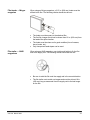
The Image display
pane
The Image display pane is the area within the window where your
images are displayed.
To change the size of the Image display pane:
1. Place the mouse cursor on the vertical line separating the display
pane from the adjacent pane.
When the cursor changes to a horizontal size bar, press and hold the
left mouse button and drag the cursor to the right or left until the desired
size of the pane is achieved.
A-61133 March 2003
2-41
The Status bar
The Status bar indicates the application name, the image address of the
image that is displayed and whether or not it is in Film or Programmed
mode. Informational messages may also be displayed in the Status bar.
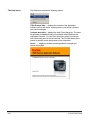
NOTE:
•
2-42
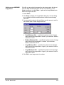
If IMC is enabled in Application setup, and the film currently
loaded in the scanner has lead end code, Film will be displayed
in the Status bar at the bottom of the main window. The
information contained in the lead end code can be accessed
by clicking on Film in the Status bar. The Film Mode Info dialog
box will be displayed with the following information:
Click OK to close the dialog box.
A-61133 March 2003
3
Using the Software
After you have reviewed Chapter 2, Getting Started, you will be ready to
start using the Application Software.
Images can be retrieved from film by using the scanner. This chapter
provides procedures for:
•
•
•
•
•
•
•
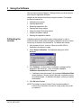
Calibrating the
scanner
Calibrating the scanner
Opening applications
Retrieving images from film
Opening and saving images
Using the Image Processing options
Using the Annotation options
Resizing the Application window
Calibration optimizes the optical system of the scanner in order to
achieve the best overall quality of images. Calibrate the scanner at least
once a day or whenever it is powered on. To calibrate the scanner:
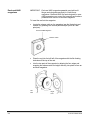
1. If the scanner is not on, turn it on. When one of the LEDs is
illuminated, the scanner is ready.
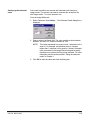
2. Select Setup>Calibration. The Calibration dialog box will be
displayed:
3. Click Calibrate. As the scanner is calibrated, messages will be
displayed in the Action box. Upon successful calibration,
Calibration Succeeded will be displayed.
•
If calibration was unsuccessful, the message Calibration Failed
will be displayed. Be sure that all cables are connected securely
and calibrate again. If calibration fails again, contact your system
administrator.
4. Click OK when finished.
NOTE: The default is to have Perform Pixel Correction enabled. If
Perform Pixel Correction is turned off, image quality may not be
as expected.
A-61133 March 2003
3-1
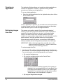
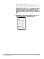
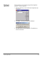
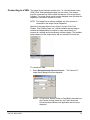
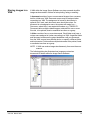
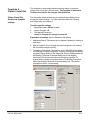
Opening an
application
The Application Software allows you to select an existing application or
create a new application. Chapter 4, Application Setup, provides
procedures on setting up new applications.
To use an existing application:
•
Select the desired application from the Application drop-down list box
on the Control Panel:
Once an application is selected, you can make use of all its parameters
to retrieve images from film, use the image processing and annotation
options and save, print or e-mail the images as desired.
Retrieving images
from film
The scanner can handle a variety of film formats and methods of
indexing. It has search programs to handle duo, duplex, duo/duplex or
simplex film formats with one-level, two-level, or three-level image
marks. It can also be used to do odometer searches of film that
contains no, or poor quality, image marks. For more information see the
section entitled, “Using the odometer mode” later in this chapter.
When retrieval is under CAR control, you must have CAR Interface
Software installed and the CAR parameters defined in the CAR setup.
IMPORTANT: Before retrieving images from microfilm, be sure the
kinks are removed from the film. Failure to remove the
kinks may cause threading problems.
To retrieve images from film:
•
Insert the microfilm, which contains the desired image in the film slot
of the scanner. You can then navigate through the film in several ways.
For more information on the following features, see Chapter 2.
Ø By using the Navigate menu.
Ø By using the navigation buttons on the Control Panel.
NOTE: You must enable Plus Indexing (typically, Plus Indexing is
disabled) in the current application when using Batch Scan
or plussing across chapters to allow you to cross chapter
boundaries. For more information see the section entitled,
“Setting values on the General tab” in Chapter 4.
Ø By using the Image Retrieval keypad.
3-2
A-61133 March 2003
Searching for next
occurrence of an image
address
The Search Again function allows you search for the next occurrence of
an image address on a roll of film.
To use the Search Again function:
•
Select Navigate>Search Again. The scanner will begin searching
the roll for another occurrence of the current image address.
NOTE: Film must have Random Batch Code to find another
occurrence of the image address. If found, it will stop at
the image, scan and display it. If not found, it will report
Image not found.
Using the odometer
mode
The Odometer mode allows you to search film by odometer units rather
than image marks. The value of an odometer unit is determined by the
odometer scale defined during Application setup.
To retrieve images using the odometer mode:
1. Select the desired odometer mode application.
2. Advance to a position on the film that you want to establish as your
reference point.
3. Enter the odometer unit preset value, if any, then select Set A, on the
Image Retrieval keypad.
4. To initiate a retrieval, enter the desired odometer unit value, then
select Srch, on the Image Retrieval keypad.
NOTE:
If the odometer scale is equal to or greater than 1 inch, a
format of X.XX must be used to enter the odometer unit
value. If the odometer scale is less than 1 inch, a format of
X must be used to enter the odometer unit value.
Examples:
A-61133 March 2003
•
If the odometer scale is 1 inch, then 1 odometer unit equals 1 inch.
To advance 180 inches into the film, enter 180.00 in the Image
Retrieval keypad.
(180 inches ÷ 1 inch per odometer unit = 180 odometer units)
•
If the odometer scale is 5 inches, then 1 odometer unit equals 5inch.
To advance 180 inches into the film, enter 36.00 in the Image
Retrieval keypad.
(180 inches ÷ 5 inches per odometer unit = 36 odometer units)
•
If the odometer scale is 12 inches, then 1 odometer unit equals 12
inch. To advance 180 inches into the film, enter 15.00 in the Image
Retrieval keypad.
(180 inches ÷ 12 inches per odometer unit = 15 odometer units)
3-3
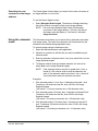
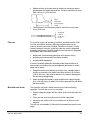
Searching for a preset
image address
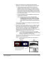
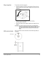
The scanner is set to count the first image mark on a roll of film as 1 or
1.0 or 1.0.0 (depending on the number of levels in the image address). If
the first image on the film has an image address or sequence number
other than 1 or 1.0 or 1.0.0, you can use the Set A or Set B function on
the keypad to specify the starting sequence number. To do this:
1.
Insert the roll of film you want to search.
2.
Enter the starting sequence number (or image address) that is
listed on the film storage box. For example: the first image on the
roll is sequence number 3.0.0.
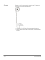
NOTE: If the sequence number (or image address) is not
documented, it may be imprinted next to the image on film,
as shown below. Select the + key on the keypad. The film
will advance to the first image. If the sequence number is
available, use it as the beginning point to search for the
actual image you want to retrieve.
Image address or
Sequence No.
3-4
3.
Select Set A or Set B (depending on the film format being used).
For more information, see “The Image Retrieval keypad” in Chapter
2.
4.
Enter the image address of the image you want to retrieve and
select Srch.
A-61133 March 2003
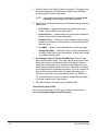
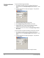
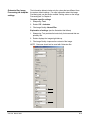
Batch scan
To automatically save and/or print a group of images from the same roll
of film, use the Batch Scan option. Before accessing Batch Scan, be
sure film is inserted into the scanner and that you have searched to the
first image address in the batch. Adjust the images as desired, then
select Navigate>Batch Scan or the Batch button on the Control Panel.
The Batch Scan dialog box will be displayed.
NOTE: You must enable Plus Indexing (typically Plus Indexing is
disabled) in the current application when using Batch Scan to
allow you to cross chapter boundaries. For more information
see the section entitled, “Setting values on the General tab” in
Chapter 4.
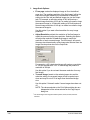
1. Select what you want to do with the images — Auto Print, Auto
Save, or Multi-Page TIFF.
•
Auto Print automatically prints all of the images.
•
Auto Save automatically saves all of the images.
•
Multi-Page TIFF automatically combines the images entered in
the Image Range field and creates single-page TIFF files. These
single-page TIFF files are then combined into a Multi-Page TIFF
file. Once combined, the system deletes the single-page TIFF
files. Multi-Page TIFF only works with 16-grayscale and bi-tonal
images.
NOTE: The name of each single-page TIFF file will be the
same name of the first image scanned in each range.
A-61133 March 2003
3-5
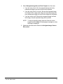
NOTE: If you want to change the path of the folder where images
will be saved, and/or the conventions to be used for naming
files, select Setup from the Batch Scan dialog box to
display the Setup Naming dialog box.
•
Enter the path in the root directory text box, or click the
Change… button to select the desired directory.
•
Change file naming conventions if desired.
•
Click OK to save the change.
More information regarding root directory and file naming conventions is
found in the section entitled “Changing Naming Convention Properties”
in Chapter 4.
IMPORTANT:
Improper setup of root directory and file naming
conventions can cause image files to be overwritten
without notification.
2. Enter the addresses (or sequence numbers) of the images to be
processed in the Enter Image Range field. Individual addresses can
be entered, and/or a range(s) of addresses. Use a dash to separate
the start and end values of a range, and a semicolon to separate
individual addresses and ranges.
Following are some examples:
•
To enter multiple ranges for 1 level film: 1-5;7-9
•
To enter multiple ranges for 2 level film, including individual
addresses: 1.0-1.5;3.0;4.10-4.30
NOTE: To accommodate European keyboards, a comma can be
used in place of a period in an address, e.g., 1,01,5;3,0;4,10-4,30.
3-6
A-61133 March 2003
In addition, the character “N” can be used as a wildcard to specify
various ranges. For example, in a 3-level application:
•
When an image has already been retrieved and is displayed, to
enter a range for next address to first address in next chapter:
-3.1.n, where 3 is the current book and 1 is the current chapter.
•
When an image has already been retrieved and is displayed, to
enter a range for next address to first address in next book:
-3.n.n, where 3 is the current book.
•
When a roll of film has been threaded but no images have been
retrieved, to enter a range for all images on a roll: -n.
•
A range of 255.3.1-255.4.n would result in the saving and/or
printing of all images in Chapter 3, Book 255 through the last
image in Chapter 4, Book 255.
3. If desired, use the Display Time slider bar to change the amount of
time you want the image displayed before moving to the next image.
4. Select Start to begin scanning. If you want to temporarily suspend
scanning (i.e., to change an image processing value from the
Control Panel, such as; Brightness, Contrast, Despeckle, etc.), click
Pause. You can then click Start to resume scanning, or Close to
stop scanning and close the Batch Scan dialog box.
NOTE:
If an unplanned interruption occurs while batch scanning is
being performed, search to the image you want to start at
and reinitiate batch scanning from that point.
5. When batch scanning is complete, the message Batch Process
finished is displayed. Click OK on the message box.
6. If you want to continue batch scanning, repeat the steps above,
otherwise you can click on Close to close the Batch Scan dialog
box.
A-61133 March 2003
3-7
Opening images
You may want to open an image that has been previously saved. To do
this:
1. Select File>Open Image…. The Open Image dialog box will be
displayed:
2. Select the desired directory using the Look In drop-down box and
tool buttons.
3. Select the file type from the Files of type drop-down box.
4. Select the image file you want from the display box, or enter the file
name of the desired image.
NOTE: Multi-page TIFF files cannot be opened using the Application
Software.
5. Click Open. The file you selected will be displayed in the Image
display pane.
3-8
A-61133 March 2003
Saving an image
You can save a previously saved image to another file or save a new
image using a non-default film name and/or path by using the Save As
option. To do this:
1. Select File>Save As…. The Save As dialog box will be displayed:
2. Enter a new file name.
3. Select the directory where you want the file to reside.
4. Select the file type and compression from the Save as type dropdown list.
•
If the image was scanned as bi-tonal, the default is TIFF file type
and Compression G3 (bi-tonal) (*.tif).
•
If the image was scanned as 16 Gray, the default is TIFF file type
and Compression JBIG (16 Gray) (*.tif).
•
If the image was scanned as 256 Gray, the default is TIFF file
type and Compression JPEG (256 Gray) (*.jpg).
5. Click Save.
A-61133 March 2003
3-9
Printing an image
The Application Software allows you to print images individually or group
them in folders and print them. A print utility program must be installed
for the Print options to work.
1. Select File>Print. The Print Options dialog box will be displayed.
2. Select the desired printer. You can change the destination printer
and other print properties by selecting Setup Printer…
3. Change the Scale Mode, if desired. Options are: Original Size
which will print the image at the original scanned size, or Fit to Page
which will size the image so it fits on the selected paper size.
4. Change the Auto Rotate option, if desired. Options are:
•
None no rotation will occur.
•
90° clockwise prints the image rotated 90° to the right
based upon the current image position.
•
90° counterclockwise prints the image rotated 90° to the
left based upon the current image position.
5. If you want any annotation that you created to be printed on the
image, click the Print Annotation box.
6. If you only want a portion of the image to be printed, click the
Selection Only box. The portion to be printed must be rubber-bandselected on the display before accessing the Print Options dialog
box.
7. Click OK when all the desired options have been specified.
NOTE: Popup notes can be viewed but not printed.
3-10
A-61133 March 2003
To print a folder of images:
1. Click on the folder to print in the Thumbnail pane with the right
mouse button.
2. Select Print from the Popup menu. The images will be printed using
the current print options.
For detailed procedures on how to use the printer software package,
see the instructions provided with your printer software.
Faxing an image
The Application Software allows you to fax images individually or group
them in folders and fax them. The Fax utility must be a printer driver
type.
1. Select File>Fax. The Fax Options dialog box will be displayed.
2. Select the desired fax machine. You can change the destination fax
machine and other fax properties by selecting Setup Fax…
3. Change the Scale Mode, if desired. Options are: Original Size
which will print the image at the original scanned size, or Fit to Page
which will size the image so it fits on the selected paper size.
4. Change the Auto Rotate option, if desired. Options are:
•
None no rotation will occur.
•
90° clockwise faxes the image rotated 90° to the right
based upon the current image position.
•
90° counterclockwise faxes the image rotated 90° to the
left based upon the current image position.
NOTE: Popup notes can be viewed but not printed.
5. If you want any annotation that you created to be printed on the
image, click the Print Annotation box.
6. If you only want a portion of the image to be faxed, click the
Selection Only box. The portion to be faxed must be rubber-bandselected on the display before accessing the Fax Options dialog box.
7. Click OK when all the desired options have been specified.
A-61133 March 2003
3-11
To fax a folder of images:
1. Select on the folder to fax in the Thumbnail pane with the right
mouse button.
2. Select Fax from the Popup menu. The images will be faxed using
the current fax options.
For detailed procedures on how to use the fax software package, see
the instructions provided with your fax software.
E-mailing images
The Application Software allows you to e-mail images individually or
group them in folders, then e-mail them.
NOTE: A MAPI utility will provide immediate attachment of the file. A
non-MAPI utility will require using the utility’s ability to attach
files previously created.
To e-mail an image:
1. Select File>Send as eMail. The dialog box associated with the email software you are using will be displayed.
2. Select the desired options.
3. Click OK.
To e-mail a folder of images:
1. Click on the folder to e-mail in the Thumbnail pane with the right
mouse button.
2. Select either E-mail or E-mail Multi-Page from the Popup menu.
The images will be e-mailed using the current e-mail options.
For detailed procedures on how to use the e-mail software package, see
the instructions provided with your e-mail software.
3-12
A-61133 March 2003
Cropping images
Use the Crop option to save or print only the significant part of an image.
The area inside the yellow rectangle will be retained and the area
outside the rectangle will be removed. Make any desired image
processing changes before cropping. To crop an image:
1. Place the mouse cursor at a corner of the area you want to crop.
2. Press and hold the left mouse button and drag the mouse diagonally
over the area you want to keep, then go to select Edit>Crop.
The portion of the image you drew the rectangle around will remain
displayed and fill the window.
3. Print, fax, e-mail or save the portion of the image as desired.
Setting Manual and
Automatic duplex
processing
Duplex processing is for applications that use checks or small items.
Duplex Processing allows you to arrange the front and back sides of an
image from duplex film vertically rather than horizontally. Separate
image processing parameter values can be specified for front and back
images. The front and back images can be saved in separate files, or
together in one file.
1. From the Image Processing Control Panel, select Manual from the
Duplex Processing drop-down box.
NOTE: If Primary is selected in the Scan Area, image processing
selections will be applied to the front and back of an image.
Select Manual
A-61133 March 2003
3-13
2. Retrieve an image that you want to duplex process. The Duplex
Processing dialog box will be displayed showing the image area
defined in Application setup.
Selection tool
Zoom Area tool
Image Area tool
Front Selection tool
Back Selection tool
3-14
Zooms in on the image area.
Zooms in on the image area.
Activates the green rectangle. This tool
allows you to draw a rectangle around
both images and define both images as
once.
Activates the red rectangle. This tool
allows you to draw a rectangle around
one image and defines it as the front
image.
Activates the blue rectangle. This tool
allows you to draw a rectangle around
one image and defines it as the back
image.
A-61133 March 2003
3. Either a red rectangle or blue rectangle will be automatically
displayed, or one green rectangle, depending on previous actions.
•
The red rectangle is used to define the front, and the blue
rectangle is used to define the back. You can either use the
handles to resize the current rectangles or use the Front and
Back selection tools to draw new rectangles. Click with the left
mouse button to delete the current rectangle. Press and hold the
left mouse button and drag, to redraw a rectangle of the desired
size in the desired locations.
•
The green rectangle provides the capability to define both front
and back with one rectangle.
NOTE: When the left mouse button is released, duplex
processing will be automatically initiated, the Duplex
Processing dialog box will close and the selected area
will be displayed in the Image pane. You must specify
border options, if desired, prior to using the Image Area
tool.
When the front and back areas are defined and any border options
are designated, click OK.
4. If you want to define a clear border(s) at the top, middle and bottom
of the image, you can make an entry in the Borders fields. Valid
values are 0 to 1000. A value in the Top field designates a blank
area at the top of the front image. A value in the Middle field
designates a blank area between images and a value in the Bottom
field designates a blank area below the back image.
NOTE:
The Top, Middle and Bottom options are only available
when you select Scanned Image Size on the Page Layout
dialog box (accessed from the Output tab).
You can use the Top, Middle and Bottom border areas for annotation
purposes. See the example below.
NOTE: No attempt was made to optimize the image quality of
these images.
Before
After
(in Duplex Processing dialog box)
(In Image area)
Dear Mr. Smith: Here is the check
you requested.
The space between the front and
back of the check was created by
entering a value in the Middle field
using the Border option.
A-61133 March 2003
3-15
5. If you did not get the image area you want, click on the Reprocess
button on the Control Panel to redisplay the Duplex Processing
dialog box and repeat the above steps.
6. When the desired results are achieved, select Automatic to apply
the duplex processing values to subsequent scans. You can select
Front (or Back) in the Image Processing Control Panel scan area
and adjust the brightness (and other image processing values) to
apply separate values to front and back.
NOTE: If Overscan is enabled, the Duplex Processing dialog box
will contain two additional tools (Previous Block and Next
Block) and a field named Overlap By One.
♦ Previous Block
allows you to decrement and
scan by a block of images rather than one image at a
time. For example, if images 48-52 are displayed,
Previous Block will result in images 43-47 being
displayed, rather than images 47-51.
♦ Next Block
allows you to increment and scan by
a block of images rather than one image at a time. For
example, if images 48-52 are displayed, Next Block
will result in images 53-57 being displayed, rather than
images 49-53.
♦ Overlap By One allows you to retain one image
from the current block when navigating with Previous
Block or Next Block. For example, if images 48-52 are
displayed, and Overlap By One is enabled, Next
Block will result in images 52-56 being displayed.
Use the appropriate tools to select the desired image area
then click OK. The selected area will be displayed in the
Image pane in the main application window.
3-16
A-61133 March 2003
Rotating an image using duplex processing
If you want to rotate an image 90° when you are using duplex
processing, you can use either the Rotation option on the Control
Panel, or select the Rotate toolbar button. Depending on which
option/tool you use, the results will be displayed differently as shown
below:
Before Rotation:
After Rotation:
If you choose the Rotation
option on the Control Panel:
A-61133 March 2003
If you choose the Rotate toolbar button:
3-17
Annotating an image
The Annotate option allows you to highlight a particular area of an image,
blank out information on an image or add a note to an image before
printing, faxing or saving. You can use this feature to mask confidential
information or add a customer message on a requested image.
NOTES:
•
The Ellipse option is not available in this release of software.
•
Before using the Annotation options, set the crop and image
processing parameters to be sure the image is the way you want it.
•
To be sure annotation is printed, the Print Annotation option must
be enabled in the Print Setup or Fax Setup dialog box.
The Annotate options, such as Highlight, Hollow Rectangle, Freehand
line, Polyline, and Arrow allow you several different drawing options. The
Annotation Toolbox allows you to specify line width, color and arrow
head direction and type.
IMPORTANT:
Using Redact, Highlight,
Hollow Rectangle, or
Freehand Line options
For a more detailed description of each option, see
“The Annotate menu” and “The Annotation Toolbox” in
Chapter 2.
To use these options, follow the steps below:
1. Select the desired option from the Annotate menu.
2. Place the cursor on the position where you want to start to highlight,
blank-out, etc.
3. Press and hold the left mouse button and drag the cursor over the
desired area and release the mouse button when finished.
NOTE:
If you want to change the highlight color, open the
Annotation toolbox and choose the desired color.
Using the Polyline option To use the Polyline option:
1. Select Annotate>Polyline.
2. Place the cursor on the position where you want to start to draw.
3. Press and hold the left mouse button and drag the cursor in the
direction you want the line to go, releasing the button each time you
want to start a new angle.
4. Double-click the right mouse button to deactivate the Polyline tool.
3-18
A-61133 March 2003
Using the Text option
To add text to your image:
1. Select Annotate>Text.
2. You can change the color and/or font on the message by using the
color palette and Font button on the Annotation Toolbox.
3. Click the left mouse button to place the cursor where you want to
add a text message.
4. Type the desired message.
5. When you have finished the text message, click the right mouse
button to deactivate Text annotation.
Adding a note
You can attach a note to an image by using the Popup option.
1. Select Annotate>Popup. The PopUp window is displayed.
NOTE:
Depending on your last action, you may need to click the
left mouse button to display the PopUp window.
2. Enter the text of your note on the PopUp window.
3. When finished, click OK. The note will be displayed on the image as
an icon.
To read annotation notes:
•
Select Annotate>Select, then double click on the note’s icon in the
image.
NOTE: Popup notes can be viewed but not printed.
A-61133 March 2003
3-19
Loading images
Use the Load Image… option to load a different image file into memory.
1. Select Annotate>Load Image…. The Load Image dialog box will be
displayed:
2. Select the desired directory.
3. Select the file type from the Files of type drop-down box.
4. Select the image file you want, or enter the file name of the desired
image.
5. Click Open. The file you selected will be displayed in the Image
display pane.
3-20
A-61133 March 2003
Creating a canned
annotation file
The Canned option allows you to save annotation created for an image,
for use on other images. This option is useful if you have many images
that you want to apply the same annotation information to.
1. Retrieve an image.
2. Using the Annotation Toolbox and tools, create the desired
annotation.
3. Select Annotate>Canned>Save. The Save Canned Annotations
dialog box will be displayed:
4. Select the folder where you want the annotation file to be saved.
5. Enter the desired file name. The file will be saved with a .ann file
extension.
6. Click Save.
A-61133 March 2003
3-21
Using canned
annotations
Once you have created annotation files, you can use the information in
the annotation files to add the same information on other images. To do
this:
1. Retrieve the image you want to annotate.
2. Select Annotate>Canned>Load. The Open Canned Annotations
dialog box will be displayed:
3. Select the desired annotation file.
4. Click Open. The annotation will be placed on the currently displayed
image. For example:
Book 2 Image Using the
Annotation Toolbox, the Text,
Highlight and a Hollow Rectangle
options were added to this image.
These annotations were then
saved as an annotation file.
3-22
Book 3 Image using the
annotation file created on the Book
2 Image, the same annotation
options were applied to this
image.
A-61133 March 2003
Deleting annotation
To delete annotation:
1. Select Annotate>Select, and click on the annotation you want to
delete.
2. Press the DEL (delete) key on the PC keyboard. The annotation will
be deleted.
Resizing the
application window
The Application window can be resized. To do this:
1. Start the Application Software. Click the Restore button in the Title
bar. (The button will toggle to Maximize.)
2. Right mouse click on the Title bar to display the popup menu, and
select Size.
3. Press the desired keyboard arrow key, e.g., to resize from the top of
the window, press the Up arrow key. Drag the mouse to resize, then
click with the left mouse button.
4. Repeat Steps 2 and 3 if necessary.
5. Once the window is sized, you can move it to the desired location by
dragging from the Title bar.
A-61133 March 2003
3-23
Deleting annotation
To delete annotation:
1. Select Annotate>Select, and click on the annotation you want to
delete.
2. Press the DEL (delete) key on the PC keyboard. The annotation will
be deleted.
Resizing the
application window
The Application window can be resized. To do this:
1. Start the Application Software. Click the Restore button in the Title
bar. (The button will toggle to Maximize.)
2. Right mouse click on the Title bar to display the popup menu, and
select Size.
3. Press the desired keyboard arrow key, e.g., to resize from the top of
the window, press the Up arrow key. Drag the mouse to resize, then
click with the left mouse button.
4. Repeat Steps 2 and 3 if necessary.
5. Once the window is sized, you can move it to the desired location by
dragging from the Title bar.
3-24
A-61133 March 2003
4
Application Setup
This chapter provides the following:
•
How to access the Application Setup option.
•
Procedures for setting up a new application.
•
Procedures for modifying and deleting existing applications.
Kodak provides predefined applications, for more information see
Appendix D, Productivity Tools.
Accessing
Application Setup
Retrieval applications can be created, modified and deleted using the
Application Setup option accessed via the Setup menu.
•
Select Setup>Application. The Select Application dialog box will be
displayed:
When the Setup Application dialog box is displayed, you may need to
use the arrow keys located at the top of the dialog box to access all of
the tabs.
A-61133 March 2003
4-1
Setting up a new
application
The Setup Application dialog box allows you to predefine retrieval and
image processing parameters for a specific application. Click on each
tab to set all the desired values. Do not click OK until you have made all
of your selections on all of the tabs.
All tabs on the Setup Application dialog box have the following buttons:
OK — saves the values set on all of the tabs.
Cancel — closes the dialog box without saving any changes.
Help — displays the on-line help for the tab that is currently active.
Setting values on the
General tab
4-2
1. Application Name . Enter any standard keyboard character(s), up to
20 characters.
A-61133 March 2003
2. Search Program. Select the Search Program based upon the
image marks on film you will be searching. These search programs
are identified in Appendix B, Search Programs. Be sure the correct
program is selected to match the film index format and image mark
location channel.
An odometer mode search program is also available, for use with
film that contains no image marks, or image marks of poor quality.
3. On Each Scan. If you want to automatically save or print each time
you scan, check the appropriate box: Auto Save and/or Auto Print.
Auto Print should only be used if you are sure the film image quality
is excellent and consistent.
•
Auto Overwrite Image. Select this option to eliminate the
message displayed to the user that they are about to overwrite
an existing file.
•
No Save Prompt. Select this option to eliminate the message
that allows the user to save the currently displayed image.
•
Auto Back Removal: for duplex images only. Automatically
removes the back of the image if the size of the image (back) is
less than the size specified in the Removal Threshold box.
NOTE: The Separate Front and Back option on the Image
Processing tab must be enabled to use this function.
•
A-61133 March 2003
Removal Threshold box: Removal Threshold is used in
conjunction with the Auto Back Removal option. A value from 1K
to 100K can be entered in the box. The scanner will use the
value entered to determine whether to remove the back of a
duplex image. If the size of the back of the image is less than or
equal to the value in this box, the back image will not be printed
or saved. This option is available for both bi-tonal and grayscale
images.
4-3
Determining the threshold value
Follow the procedure below to determine the threshold value.
•
Disable Auto Back Removal.
•
Set up your application with the options that you will be using
with Auto Back Removal (i.e. auto cropping, scan output
types, etc.).
•
Insert a roll of film that you want to use the Auto Back
Removal feature into the scanner.
•
Scan a batch of images with and without content on the back
of the image.
•
Determine the largest file size of the blank backs and the
smallest file size of the non-blank backs. To view the file
sizes, Document Folder needs to be enabled
(View>Document Folder), select the folder when the images
are saved, and then select View>Thumbnails> Details.
•
Set the threshold value to the size somewhere between the
largest file size and the smallest file size.
4. Plus Indexing. Enable Plus Indexing if you want to advance
across chapters within the film. If it is not enabled, you will not
be able to advance across chapters within the film.
NOTE: Plus Indexing must be enabled when using Browsing
or Batch Scan.
4-4
A-61133 March 2003
Setting values on the
Image Marks tab
Use the Image Marks tab to define the type of image marks on the film
associated with the application you are setting up. Do not click OK until
you have made all of your selections on all of the tabs.
1. Select the Image Marks tab.
2. Image Marks. Select the type of image marks on the film, either
ANSI/AIIM or Other.
A-61133 March 2003
•
Select ANSI/AIIM if the image marks on the film meet ANSI
standards (such as those on film created by a Kodak
microfilmer). See Appendix A, Microfilm Information for more
information regarding image marks.
•
Select Other, if the image marks were created by a non-Kodak
microfilmer and/or do not meet the ANSI standards. If you select
Other, click Setup to display the Image Marks dialog box. See
the section entitled, “Setting up non-ANSI/AIIM image marks” later
in this chapter for more information.
4-5
3. Image Mark Position. Select the image mark position on the film.
•
•
Choose Lead Edge if the image marks are aligned with the lead
edge of the image.
Choose Other if the image marks are located in any other
position than the lead edge and then select Setup… to display
the Image Mark Position dialog box. See the section entitled,
“Determining the image mark position” later in this chapter for
more information.
4. Image Mark Polarity. Select either Positive or Negative.
•
•
Choose Positive if the image mark is clear and the film has a
black background.
Choose Negative if the image mark is black and the film has a
clear background.
5. Count Splices. Make a selection from the Count Splices list box if
you have splices on your film. Count Splices specifies whether
splices on the film are to be counted as image marks. For more
information about film splicing, see Appendix A, Microfilm
Information.
•
•
•
•
No — do not count splices.
Yes, as Large — count splices as large image marks.
Yes, as Medium — count splices as medium image marks.
Yes, as Small — count splices as small image marks.
6. Image Management Code. Check the Enable checkbox to enable
the scanner to read Kodak’s Image Management Code (IMC). For
more information about Image Management Code see Appendix C,
Glossary.
NOTE: This option only works with Kodak’s Image Management
Code.
4-6
A-61133 March 2003
7. Preset. The Preset option is used when the image address begins
at something other than one (1).
•
•
If Set to First image address is enabled, the preset image
address will be assigned to the first image mark on the film.
If Set to First image address is disabled, the preset image
address assigned to the first image mark on the film will be
incremented by one from the image address that was entered.
NOTES regarding Preset:
•
•
•
The scanner will start counting at 1 (or 1.0 or 1.0.0) unless a
preset image address is specified.
The A and B presets remain in memory until the film is refiled.
The preset image address that is specified will be affected by the
Preset parameter in Application setup.
− If the Preset parameter is enabled, the specified Channel A
preset will be assigned to the first image mark in Channel A.
The specified Channel B preset will be assigned to the last
image mark in Channel B.
−
If the Preset parameter is disabled, the specified Channel A
preset will be incremented by one and that value will be
assigned to the first image mark in Channel A. The specified
Channel B preset will be decremented by one and that value
will be assigned to the last image mark in Channel B.
8. Odometer Scale. Setting up an odometer scale allows you to
search film by odometer units rather than image marks. To set this
value, select Setup… to display the Odometer Scale dialog box.
See the section entitled, “Setting the odometer scale” later in this
chapter for more information.
A-61133 March 2003
4-7
Setting values on the Film
tab
The film format and reduction ratio of the images on film can be defined
using the Film tab. Do not click OK until you have made all of your
selections on all of the tabs.
1. Select the Film tab on the Setup Application dialog box.
2. Film Format. Select the Film Format from the list box:
•
•
•
4-8
Simplex — one image appears across the width of the film.
Duplex — the front and back of the same image appears across
the width of the film.
Duo/Duo Duplex — images are filmed to the end of one side
(channel) of the film, then other images are filmed on the other
side (channel).
A-61133 March 2003
3. Film Reduction. Select the Film Reduction ratio for the film used. It
is important that this value be accurate to achieve the correct print
size results. Select a value from 1 to 59.
4. Overscan. If desired, select a value in the Images Before and/or
Images After list boxes. Overscan is intended for use with singlelevel check, or similar-type applications (do not use with images
larger than 8 ½” x 5” or A5).
Enter a value from 1 to 5 in the Images Before and/or Images After
fields. For example, if you enter 2 in the Images Before field, the
scanner will begin scanning 2 images before the image address you
actually requested. If you enter a number in the Images After field, it
will scan that number of images past the one you requested.
This function is useful when the image indexing is not perfectly
accurate and may be off by a few images. When used with the
Image Area definition, you will be able to view several consecutive
checks on each scan.
NOTES:
•
The larger the scan area, the larger the file size will be to
process.
•
When Overscan values are specified, you should also enable
Auto Scan Length, to achieve the best results.
5. Image Area. Select one of the image area options Minimum,
Short, Medium, Long, Maximum and User defined. The following
illustration shows the difference between the smallest (Minimum)
and the longest (Maximum) image area options. The Short, Medium
and Long options will display an image area between the Minimum
and Maximum image area.
Minimum Image Area
A-61133 March 2003
Maximum Image Area
4-9
The User defined option provides the greatest efficiency and flexibility
in choosing the image area that meets your specific application
needs since it allows you to customize the image area. If you select
User defined, the Setup… button will be activated. Click Setup…
to display the Select Image Area dialog box. See the section entitled,
“Setting a User Defined image area” later in this chapter for more
information.
NOTE: If User defined is selected, but the area is not subsequently
defined, the software will default to using Minimum.
6. Auto Scan Length: Allows the software to determine scan length
based upon the distance between image marks. Auto Scan Length
only determines the length of the image, not the width. The width is
still determined by the Image Area setting.
7. Add Extra Scan Lines: Adds extra scan lines to the end of each
scanned image. If the space between the images on the film is tight,
enabling this option can help ensure that you capture the entire
image.
• If Normal resolution is selected, 100 scan lines will be added.
• If Enhanced resolution is selected, 200 scan lines will be added.
Special Processing Controls
The following options are used to improve auto cropping, deskew and
border removal.
8. Deskew Algorithm: this option requires Auto Deskew to be enabled
on the Control Panel. Two deskew algorithms are available, Normal
and Best.
•
•
Normal processes the image faster and does a good job at
deskewing the image.
Best takes longer to deskew the image and provides the best
deskewed quality.
Minimum Angle: enter a deskew angle from 0 to 45 degrees. The
software will deskew the scanned image if the angle of skewed
image is equal to or more than the value in this field. It is suggested
that you set a value 5 degrees or less.
4-10
A-61133 March 2003
9. Border Removal Recursions: the number of times (one, two or
three) the system will attempt to determine and remove the
boundaries of the image. Three is the default. Longer processing
times are required for each attempt.
Even though you may enter a value of 3 in this field, the system may
remove the border the first or second time, therefore making the
third attempt unnecessary. The system will only use the number of
times necessary to remove the border, regardless of the entry in the
field.
NOTE: The Setup option is for use by Kodak Field personnel only.
10. Duplex Form: for duplex mode only. Enable this option if the front
side of the image is located on the right side of the film.
A-61133 March 2003
4-11
Setting values on the
Image Processing tab
The options on the Image Processing tab are selected based upon how
you want to alter the image. Do not click OK until you have made all of
your selections on all of the tabs.
1. Select the Image Processing tab to set the image processing
values.
4-12
A-61133 March 2003
2. Scan Area. Select an option in the Scan Area. This option
determines the area of the film that the image processing settings
are applied to.
•
Primary applies to the image area that is defined in the
Application setup.
Use Front and Back for duplex processing applications:
•
Front select Front if you want to set/change the image
processing characteristics of the front side image different from
the back.
•
Back select Back if you want to set/change the image
processing characteristics of the back side image different from
the front.
•
Film View allows image processing parameters on the Image
Processing tab to be applied in the Select Overscan and Duplex
Processing dialog boxes and Scrolling window. The default is
256 Gray.
3. Duplex Processing. If you want Duplex Processing, select Manual
or Automatic processing. For Duplex Processing you can have
different image processing settings for front and back for the
following: Contrast, Brightness, Despeckle, Sharpening, Rotate and
Border remove.
• None to process the front and back sides with the standard
horizontal view. Does not allow for separate processing of front
and back side images. This is the default.
• Manual the Duplex Processing dialog box is displayed after
each scan, which allows you to specify the front/back areas
(masks) of the image.
• Automatic uses the last specified manual area settings to
automatically display the duplex image in vertical duplex
processing view. If the image size changes, then the masks will
have to be changed. If the distance between image marks vary,
then the masks may also have to be changed.
After the front and back sides are displayed vertically, you can then
apply separate image processing values to the front or back, if
desired.
If you choose Automatic duplex processing, you must first set the
Manual duplex processing settings. See the section entitled, “Setting
Manual and Automatic duplex processing” in Chapter 4 for more
information.
A-61133 March 2003
4-13
4. Separate Front and Back check this option when you want to
create two separate image files; one file for the front of the duplex
image and one file for the back of the image (see the illustration
below). This is useful for printing fronts and backs on separate
sheets of paper.
With Separate Front and Back enabled two separate files
100F.tif
100B.tif
With Separate Front
and Back disabled
one file
100.tif
The Naming Convention Properties dialog box, accessed from the
Output tab, allows you to specify the file naming convention. If
values are not specified for the Areas parameters, file names that
distinguish between duplex front and back cannot be created.
Therefore, you must use the Areas parameters (Primary, Front and
Back) when Separate Front and Back is enabled. For more
information, see “Changing naming convention properties” later in
this chapter.
5. Resolution. Select the type of resolution desired. Normal is usually
best for films with reduction ratios less than 40X. Enhanced is
usually best for films with reduction ratios greater than 40X. Try both
on your films and decide which is best for your needs.
4-14
A-61133 March 2003
6. Contrast. Select a Contrast setting from Low ( ) to High ( ) or
enter the contrast value in the text field. Valid values are 0 to 255. For
gray scale images only.
• A low contrast value produces a scanned output of mostly
midtones (more subtle change in gray levels are detected).
• A high contrast value produces a scanned output of mostly
blacks and whites (only large changes in gray levels are
detected).
7. Brightness. Select a Brightness setting from Low ( ) to High ( )
or enter the brightness value in the text field. Valid values are 0 to
255.
• A low brightness value produces a darker image.
• A high brightness value produces a lighter image.
8. Despeckle. Select a Despeckle value to reduce the amount of noise
or stray spots (specks, etc.) on an image. Select a value of 0, 1 or 2
from the list box or use the slide bar to make a despeckle selection.
The value you select will depend on how clean or speckled the
image is. If there are no specks on the image, select 0. Despeckle
is for bi-tonal images only.
9. Scan Output. Select the desired Scan Output depending upon the
type of images in the application.
•
•
•
Bi-tonal: each image will be processed as a single-page TIFF
file using CCITT Group 3 or 4 compression (for black and white
images).
16 gray: each image will be processed as a single-page TIFF file
using JBIG compression (for 16-level gray scale images).
256 gray: each image will be processed as a single-page TIFF
file using JPEG compression (for 256-level gray scale images).
NOTES:
• For Duplex Processing, the Scan Output setting must be the
same for both the Front and Back settings.
• When Film View is selected as the Scan Area, it is suggested
that you select 256 gray as the Scan Output.
10. Sharpening. Select a Sharpening option.
•
•
•
•
•
A-61133 March 2003
Normal: used to accentuate the fine details of an image. Normal
is typically used to enhance the detail of an image which
contains small print.
Low: used to enhance images containing dot matrix text and/or
images printed with shaded or colored backgrounds using
halftone screens. This option reduces background noise.
Photo: if the image is comprised mainly of photographs.
Photo & Text: if the image is a mix of text, line art, and
photographs (i.e., for check camera-sorter films).
Text: if the image is mostly text.
4-15
11.
Rotate. Select a Rotate option to specify whether images will be
rotated when displayed:
• None: to process the image in the original orientation.
• 90° Clockwise: to process the image rotated 90° to the right.
• 180° Clockwise: to process the image rotated 180° to the right.
• 270° Clockwise: to process the image rotated 270° to the right.
12.
Border. Select a Border option if desired.
• Leave: keeps the border around the image.
• Auto Crop: removes the border from around the image and
reduces the image file size. For bi-tonal and grayscale images.
• Border remove: hides the border from around the image. For
bi-tonal and grayscale images.
NOTE: When using the Border option, the entire image (all
borders) needs to be visible in the image area so the
image can be captured properly.
13.
Film Polarity. Select the Film Polarity of the film.
• Choose Positive if the original image is a clear background with
black text.
• Choose Negative if the original image is a black background
with clear text. This is the default.
14. Film Image Quality. Used with bi-tonal or gray scale output to
improve readability of images from a film that is too light or too
dark. It can also improve low contrast images. This feature widens
the range between the lightest and darkest pixel in the image.
Select one of the following options if desired:
• No Adjustment: no enhancement.
• Light Film: if film is light, it makes the dark areas darker,
making it easier to read.
• Normal Film: if film has the correct exposure but low contrast,
this option adds contrast to the image, making it easier to read.
• Dark Film: if the film is dark, it lightens the background and
other areas that should be lighter, making the image more
readable.
15. Mirror. Select Mirror if the film has been wound incorrectly on the
reel and the image appears as if it was being viewed in a mirror and
is “reverse-reading”.
4-16
A-61133 March 2003
16. Auto Deskew. Check Auto Deskew to automatically straighten the
image
NOTE: When using the Auto Deskew option, the entire image (all
borders) needs to be visible in the image area so the image
can be captured properly.
17. Overscan. Check the Overscan option to enable scanning and
display of a specified number of images before and after the image
requested. The before and after values are defined on the Film tab.
Overscan is useful for film with poor image alignment within the film
frame, such as 3890 single-level check film.
NOTE:
A-61133 March 2003
When Overscan is enabled, you should also enable Auto
Scan Length on the Film tab, to achieve the best results.
4-17
Setting values on the
Output tab
The Output tab allows you to set up file saving options, compression
level and how you want the image to be printed, faxed or emailed.
1. Select the Output tab.
2. File Saving Options. If you want to save images to a non-default
location and/or file names, select Change…. The Naming
Convention Properties dialog box will be displayed.
4-18
A-61133 March 2003
See the section entitled, “Changing naming convention properties”
late in this chapter for more information.
•
Annotation Imbedded: when this option is enabled, any
annotation that is included with an image will become part of the
image bitmap.
NOTE:
If this option is not selected and the image is saved in TIFF
format, the annotation is saved in the TIFF tags.
If the image is saved in JPEG format (whether Annotation
Imbedded is selected or not) the annotation is always
imbedded.
3. JPEG Compression: To control the quality and size of an image
you can select a JPEG compression level from Best Quality to Best
Size. Best Quality provides the best quality image but the file size
will be larger. Best Size provides a good quality image with a
smaller file size. JPEG compression levels range from -10 to +10.
4. Page Layout: Provides image size and orientation options.
• Image Size: select one of the choices from the drop-down box:
Letter, Legal, Ledger (11x17), 8 ½ x 5 ½, A3, A4, A5, A6, B4, B5
and Scanned Image Size.
• Portrait where the image is displayed in the shape of a
conventional portrait, where height is greater than width or
Landscape, where the image is displayed in the shape of a
conventional landscape painting, where width is greater than
height.
• Click Setup to display the Page Layout dialog box. See the
section entitled, “Setting page layout options” later in this chapter
for more information.
A-61133 March 2003
4-19
Changing naming
convention properties
The Naming Convention Properties dialog box allows you to change the
file naming rules and the root directory where images will be saved.
From the Output tab:
From the Output tab:
1. Select Change… from the File Saving Options. The Naming
Convention Properties dialog box will be displayed.
The software automatically creates a directory on the hard drive of
the PC and names the images. If you do not create or select a
different directory, the images will be saved to this default directory.
2. Enter the desired Root Directory. The Change… button allows you
to browse for a specific folder using Windows Explorer.
•
If you choose to enter the root directory directly in the Root
Directory text field, you cannot use a UNC name and you have
to map a drive. For more information, refer to Windows
Explorer on-line help, “UNC Name”, and “map a drive”.
•
If you use the Change… button to select a directory, the root
directory will be entered into the field correctly.
NOTE: The directory must already exist to be selected.
3. Specify the naming convention as to how you want the files saved
in the File Naming Convention area (up to 100 characters,
including the file extension).
4-20
A-61133 March 2003
The image address can be part of the name given to the image.
Special keywords are used in this field by default, they are: book
(level 3), chapter (level 2), image (level 1) and area (determines
whether the value in Primary, Front and/or Back in the Areas
section) is included in the file names.
NOTE: Front and Back values will be used only when Duplex
Processing is enabled, and Separate Front & Back is
checked (both on the Image Processing tab).
These keywords are denoted enclosed in angle brackets ( < > ).
i.e., <book.n>.<chapter.n>.<image.n><area>.TIF.
Any other non-keyword values will be used in the file name exactly
as they are specified here. You can use any alphanumeric
character, and special file naming characters, such as an _
(underscore), or - (minus sign), or space. Other special
characters are not recommended.
book, chapter and image (also referred to as: Folder, Document
and page) can use an optional parameter (.n) to indicate the
number of characters which will be saved for those parts of the file
name.
Roll or Film number can be used as an optional keyword to
indicate the roll number if available from the lead end coding on the
current roll of film.
Example 1 using the optional parameter (.n)n)
If the file naming convention was set to
<book.3>.<chapter.4>.<image.5><area>.tif, the resulting image
file name would be as follows if the current image address is
10.14.145:
•
•
•
A-61133 March 2003
If Separate Front and Back is not enabled on the Image
Processing tab and Areas-Primary is set to P, then the
resulting file name would be 010.0014.00145P.TIF.
If Areas-Primary is not defined with a P, the resulting file name
would be 010.0014.00145.TIF.
If Separate Front and Back and Duplex Processing are both
enabled on the Image Processing tab, and Areas-Front is set
to F, and Areas-Back is set to B, then the resulting file name
for the front would be 010.0014.00145F.TIF and the back would
be 010.0014.00145B.TIF.
4-21
Example 2 using no optional parameter
If the file naming convention was set to
<book>.<chapter>.<image><area>.tif, the resulting image file
name would be as follows if the current image address is
10.14.145:
•
•
•
If Separate Front and Back is not enabled on the Image
Processing tab, and Areas-Primary is set to P, then the
resulting file name would be 10.14.145P.TIF.
If the Areas-Primary is not defined with a P, the resulting file
name would be 10.14.145.TIF.
If Separate Front and Back and Duplex Processing are both
enabled on the Image Processing tab, and Areas-Front is set
to F, and Areas-Back is set to B, then the resulting file name
for the front would be 10.14.145F.TIF and the back would be
10.14.145B.TIF.
Example 3 using non-keyword value
If the file naming convention was set to: file<image>.tif, the
resulting image file name would be as follows if the current image
address is 145:
•
•
•
If Separate Front and Back is not enabled on the Image
Processing tab, and Areas-Primary is set to P, then the
resulting file name would be file145P.TIF.
If the Areas-Primary is not defined with a P, the resulting file
name would be file145.TIF.
If Separate Front and Back and Duplex Processing are both
enabled on the Image Processing tab, and Areas-Front is set
to F, and Areas-Back is set to B, then the resulting file name
for the front would be file145F.TIF and the back would be
file145B.TIF.
File naming conventions can be used to ensure unique file names
are used when saving images from multiple cartridges within the
same directory.
NOTE: The Front and Back values indicated in the Areas section
(including a blank field) should be unique or you could
overwrite your front image with the back image.
4. Click Apply to accept the values, then click OK to close the
Naming Convention Properties dialog box.
4-22
A-61133 March 2003
Setting up non-ANSI/AIIM
image marks
If the film you are retrieving images from has image marks that do not
meet the ANSI standards because the film was created by a nonKodak microfilmer, use the Other… option on the Image Marks tab to
define the image mark size.
1. Select Other.
2. Click Setup to display the Image Marks dialog box. Use this dialog
box to adjust the minimum and maximum values for each image
mark size.
3. You can enter the value in the text field or use the arrows to scroll to
the desired value for each image mark size.
•
Small Minimum Size specifies the minimum size of image
marks that will be interpreted as “small” by the scanner. Select a
value from 1 to 96.
•
Medium Minimum Size specifies the minimum size of image
marks that will be interpreted as “medium” by the scanner.
Select a value from 2 to 97.
•
Large Minimum Size specifies the minimum size of image
marks that will be interpreted as “large” by the scanner. Select a
value from 3 to 98.
•
Large Maximum Size specifies the maximum size of image
marks that will be interpreted as “large” by the scanner. Select a
value from 4 to 99.
4. Click OK to save image mark size values.
A-61133 March 2003
4-23
Determining the image
mark position
The scanner requires that the leading edge of the image marks be
located even with the leading edge of the document images. Some
microfilmers place image marks after the leading edge of document
images. The Image Mark Position enables you to work with image
marks that have been placed in a non-standard location in relation to the
images.
1. From the Image Marks tab, select Other if the image marks are
located in any other position than the lead edge.
2. Select Setup… to display the Image Mark Position dialog box.
3. Select a value from 1 to 99. The offset number will increase as the
image marks move further from the lead edge of the document. For
example:
NOTE: You cannot enter a negative offset value.
You can also use an eye loupe to measure the distance between the
image mark and the lead edge of the image. Divide this value by .003
inches. This is the offset value that will be entered in the Image Mark
Position dialog box.
4. Click OK.
4-24
A-61133 March 2003
Setting up the odometer
scale
Some older microfilms are indexed with odometer units instead of
image marks. The scanner can search odometer film as well as film
with image marks. To set an odometer unit:
From the Image Marks tab:
1. Select Odometer Scale Setup… The Odometer Scale dialog box is
displayed:
2. Enter a value in the Scale field. The value must be a whole number
between .050 and 12.0, and an increment of .050.
NOTE:
This value represents how many inches 1 odometer unit is
equal to. For example, an odometer scale of 4 inches
means that 1 odometer unit is equal to 4 inches. Odometer
units are entered in the Image Retrieval keypad to specify
the distance to advance the film during retrievals. For more
information see the section entitled, “Using the odometer
mode” in Chapter 3.
3. Click OK to save the value and close the dialog box.
A-61133 March 2003
4-25
Setting a User Defined
image area
When you are setting film parameters and you want to define a custom
image area, use the Setup option on the Film tab.
From the Film tab:
1. Select User defined from the Image Area drop-down list.
2. Click Setup… to display the Select Image Area dialog box.
3. Load the film in the scanner.
4. Enter the desired image address using the dialog box keypad. The
scanner will locate and display the requested image. The green
selection box indicates the current user defined image area and is
used to define a new image area. This will be the area that is
scanned and displayed during retrieval. You will see the full width of
the film including the image marks.
NOTE:
The current image address is shown at the top-most
image mark. If you select any image below this image
mark, the image addresses will become offset from the
actual image.
5. To activate the green selection box, click on the Image Area tool.
To change the size of the selection box, use the handles. The box
should only be as large as necessary.
To define a new image area, click the mouse with the arrow outside
of the green selection box. The box will disappear. Hold the left
mouse button and drag the cursor diagonally to define the desired
area.
NOTE: The Zoom tool may be used to enlarge the viewing area.
5. Click OK when finished.
4-26
A-61133 March 2003
Setting page layout
options
The Page Layout dialog box provides options which allow you to position
the displayed image where you want on a sheet of paper for printing,
faxing or emailing. You can also add annotation to every page
automatically.
From the Output tab:
1. Select Page Layout Setup… The Page Layout dialog box is
displayed:
2. Image Position: The Image Position option on the Page Layout
dialog box allows you to adjust the placement of the image.
•
•
•
Top Left: places the image in the upper left corner of the paper.
Centered: centers the image on the paper.
User defined: allows you to adjust the placement of the image.
When you select User defined, the Simplex/Duplex Front,
Duplex Back and Image Scale Options will be available.
NOTE:
A-61133 March 2003
If Scanned Image Size is selected as the Page Layout on
the Output tab, you cannot change the Image Position.
4-27
3. Units: Select either 1/10 Inch or Millimeter. The unit measurement
is based on paper size, not how the image is displayed on the
screen.
4. Simplex/Duplex Front: select a value for image placement on the
paper. The value you enter is equal to 1/10 of an inch (or
millimeters, depending on how your system is set up). Therefore, if
you enter 5/5 in the Top and Left fields respectively, the front of the
image will be placed in the upper left corner of the page. Refer to the
following illustrations and table to aid in image placement.
4-28
A-61133 March 2003
The following table provides the maximum values of paper width and
length:
Image Size
Letter
Legal
Ledger
8.5 x 5.5
A3
A4
A5
A6
B4
B5
Units = 1/10 inch
Maximum
Length
Width
110
85
140
85
170
110
85
55
165
117
117
83
83
58
58
41
139
98
101
72
Units = Millimeters
Maximum
Length
Width
279
216
356
216
432
279
216
140
420
297
297
210
210
148
148
105
354
250
257
182
5. Duplex Back: select a value for image placement on the paper.
The value you enter is equal to 1/10 of an inch (or millimeters,
depending on how your system is set up). Therefore, if you enter
55/5 in the Top and Left fields respectively, the back of the image will
be placed in the center of the page at the left margin. Refer to the
previous illustrations and table to aid in image placement.
NOTE: If you use the same coordinates in the Simplex/Duplex
Front and Duplex Back fields, your images will overlap one
another.
A-61133 March 2003
4-29
6. Image Scale Options:
•
Fit on page: scales the displayed image to fit on the defined
page size. The resulting resolution of the final image* will be the
same as what was defined by the combination of Reduction
setting (on the Film tab) and defined Image size (on the Output
tab). For example, a reduction setting of 24X will produce a
Normal image resolution of 233 dpi, no matter how small or large
the scanned image is. A Reduction setting of 40X will produce a
Normal image resolution of 140 dpi, no matter how small or large
the scanned image is.
Use this option if you want a fixed resolution for every image
produced.
•
Adjust Resolution: adjusts the resolution of the final image to
match the scanned image size resolution. Selecting this option
will adjust the resolution of each final image to match the
resolution of each scanned image. The final image* will remain
the same size dimensionally as the image size selected from the
Image Size drop-down box on the Output tab.
For example, a 40X check-sized image will produce a resolution
of 178 dpi, whereas an 8 1/2 x 11-sized image will produce a
resolution of 208 dpi.
Use this option if you do not want the same resolution for every
final image.
•
*
4-30
Truncate image: based on the selected paper size and the
reduction setting, the scanned image will not be scaled up or
down and may be cut off if it is larger than the defined image
size.
Use this option if it doesn’t matter if some images have been cut
off.
NOTE: The values selected on the Print Options dialog box are
independent of the values selected on the Page Layout
dialog box.
The final image is the image that will be printed, faxed, viewed, saved or
emailed.
A-61133 March 2003
6. Annotation Position: enter your text annotation in the Text box and
set the Upper Corner and Left Corner position as to where you want
the annotation to appear on every image. Your text message will
appear on every image within the batch in the designated location.
Typically annotation is positioned at the top or bottom of the image.
In order for the text annotation to print, the Print Annotation option
on the Print dialog box must be enabled.
NOTE: To stop printing the text annotation that is entered in the text
box on the Page Layout dialog box, delete it from the
annotation box.
The current date and/or time can be automatically entered along with
the annotation. To do this:
§ Enter your message text and then enter @time and/or @date. The
system will automatically generate the current time and date on
your message.
NOTE: If the 40-column CAR command (Command XXT) is used,
it will override the @time and/or @date you entered in the
text box.
A-61133 March 2003
4-31
Modifying an
existing application
Modifying applications is similar to creating a new application. Refer to
the previous section entitled “Setting up a new application” if you need a
description of the fields on the tabs.
To modify an application:
1. Select Setup>Application. The Select Application dialog box will be
displayed:
2. Select the application you want to modify from the Application dropdown box.
3. Select Modify. The Setup Application dialog box will be displayed:
4. Make any changes required on each of the tabs.
5. When all changes are made, click OK.
4-32
A-61133 March 2003
Deleting an
application
Existing applications can be deleted by using the Select Application
dialog box. To delete an application:
1. Select the application you want to delete from the Application dropdown list box.
2. Click Delete. The following message will be displayed:
3. Click Yes to delete the selected application. The application you
selected will be deleted.
A-61133 March 2003
4-33
5
Setting up CAR Applications
This chapter provides procedures that allow you to use CAR
applications with the scanner.
If you have purchased CAR functionality and if CAR does not appear on
the menu bar, call Kodak service.
The scanner can accept image addresses, commands and text
messages from a Computer-Aided Retrieval (CAR) system in three
ways:
A-61133 March 2003
•
Download image addresses and text messages are loaded in
the scanner memory registers. You recall data from one register at a
time and perform the desired search, print, fax or e-mail function for
each.
•
Batch Download commands, text messages, and image
addresses are loaded in the scanner memory registers. A message
appears when a batch download is sent to the scanner. You can
process the registers right away or later; and you can process the
registers one at a time or let the scanner automatically process the
entire download.
•
Direct search image addresses, text messages, and
commands can be sent directly to the scanner (not loaded into
registers). Only one piece of data can be sent at a time, and must
be processed before another can be sent.
5-1
Setting up CAR
communication and
modes
Before you begin processing CAR commands, CAR communication
and modes should have previously been set up. It is suggested that you
record these settings, in case you need to change them for some
reason.
Setting up CAR
communication
To set up CAR communication:
1. Select CAR>Setup>Communication… from the main window. The
Setup CAR Communication dialog box will be displayed:
2. Select the desired port you want to connect to. Do not select the
same port as the film controller.
3. Select the Start Sequence. The Start characters can be >>>, <<<,
@@@ or any printable ASCII character repeated three times. The
Start Sequence can also be set to None, for no Start sequence.
4. Select an End Sequence. The characters E, \, or <EOT> can be
used as the end of transmission characters and should ignore all
transmissions that follow the end of transmission character until the
next Start characters are received by the scanner. If no start
sequence is selected, then no particular end sequence needs to be
set.
5-2
A-61133 March 2003
Changing the CAR
communication settings
If you need to change any of the settings listed on the Setup CAR
Communication dialog box. If you change these settings, the Bits per
second, Data bits, Parity and Stop bits must match the same settings
defined on the CAR system.
To change the CAR communication settings:
1. Select the Port where you want to change the settings.
2. Click Setup…The COM Properties dialog box will be displayed.
3. If you need to make any changes in the Port settings, select the
option and change as desired.
NOTE: To restore the default values on the Port Settings tab, click
Restore Defaults.
4. Click Apply, then click OK.
A-61133 March 2003
5-3
Setting up CAR modes
Setting up CAR modes is a way to allow a remote CAR host to change
values in the application parameters. This function is used primarily to
support the A, B, and D commands. To set up CAR modes:
1. Select CAR>Setup>Modes… from the main screen. The Setup
CAR Modes dialog box will be displayed:
2. From the Mode 1 list box, select the application name that you want
to correspond with CAR Mode 1. (Command A)
3. From the Mode 2 list box, select the application name that you want
to correspond with CAR Mode 2. (Command B)
4. From the Mode 3 list box, select the application name that you want
to correspond with CAR Mode 3. (Command D)
5. Enable Multi-Page TIFF if you want to take any batch scans done
through CAR and save them as a multi-page TIFF file.
6. Click OK when all modes are set up as desired.
Sending a Ready
message
After processing a download, batch download, or direct command, you
can indicate you are ready for more input. To do this:
•
Select CAR>Ready.
NOTE: This function is applicable only when using a Kodak CAR
Interface configured as listen-talk.
5-4
A-61133 March 2003
Processing
Download requests
The Download menu allows you to start and stop downloads, batch
downloads and direct search transmissions. It also allows loading of
previously saved download and batch download files to the scanner
memory registers. Diagnostic capability is provided through the Dump
menu options.
Starting and stopping a
Download job
When the CAR Interface Software is installed, the Application Software
starts automatically, with Start Download Job enabled. No action is
required unless an error message indicates the need to restart the CAR
application, which is done by selecting Download>Start Download
Job.
Loading a previously
saved Download file
To open a previously saved Download file:
1. Select Download>Load Download… The Open Download File
dialog box will be displayed:
2. Enter the file name of the file you want to download or select the file
from Look In.
3. Click Open.
A-61133 March 2003
5-5
Dumping jobs
Occasionally it may be necessary to view the data that is sent by the
host computer and analyze it. The Dump menu options are intended
for diagnostics, not everyday operation. The following options are
provided:
View Dump… allows you to view the data that is sent by the CAR
host computer to the scanner in a CAR download. See the next section
entitled “Viewing CAR data” for procedures.
No Dump when selected, does not allow the capture of data for
saving or review. This is the normal operating mode.
Dump Job captures only data between Start/End transmission
characters.
Dump All captures all data received by the scanner CAR port.
NOTE: If you use the Dump Job option or Dump All option to open the
View Dump dialog box, and the dialog box is subsequently
closed, you must reopen the dialog box by selecting the View
Dump menu option.
Viewing CAR data
The CAR menu allows you to view the data that is sent by the host
computer to the scanner in a CAR download.
1. Select Download>View Dump… The View Dump dialog box will be
displayed with the CAR data:
NOTE: Unprintable ASCII characters, such as Start of Text, are
shown as <STX> in the View Dump dialog box.
2. Select Save… if you want to save the file to send to Kodak or your
integrator for analysis or select Clear to clear the screen and
perform another download.
3. Click OK.
5-6
A-61133 March 2003
CAR registers
The Registers menu allows you to save or view what is currently loaded
in the registers, or load a previously saved file to the registers. You can
also start a batch download using the Registers function.
Saving and loading
registers
The Save and Load functions are primarily used for diagnostic
purposes.
To save the current contents of the registers:
1. Select CAR>Registers>Save. The Save Registers dialog box will
be displayed:
2. Select the folder where you want to save the register information.
3. Enter a new file name.
4. Select a file type.
5. Click Save.
A-61133 March 2003
5-7
To load the registers with a previously saved file:
1. Select CAR>Registers>Load. The Load Register File dialog box
will be displayed:
2. Locate and select the desired file.
3. Click Open.
Starting a Batch
download and using
View registers
During a batch download, commands, text messages, and image
addresses are loaded in the scanner memory registers. A message
appears on the scanner PC when a batch download is received. You
can execute the registers right away or later; and you can execute the
registers one at a time or let the scanner automatically execute the
entire download.
You can load the registers from the CAR system or from a previously
saved download file. (Loading from a file is used primarily for
diagnostics.)
To execute the registers from the scanner you can use the
CAR>Registers>Start Batch function, or use the CAR>Registers>
View function. Use the View function if you want to verify that the
download has been received and is ready to be executed or if you want
to change the order in which the download is executed.
5-8
A-61133 March 2003
Using the View Registers function
The CAR Registers dialog box allows you to change the order in which a
download is executed. Following is a summary of the functions available
on the CAR Registers dialog box.
Start Register displays the next register to be executed.
Exec. Register displays the register currently being executed.
Command displays the command currently being executed.
Set Executed as each register is executed, YES will be posted in
the Executed column of the list box. If you want to re-execute a register,
double click on the register you want to re-execute and click Set
Executed. This will change the YES to NO and allow the register to be
re-executed.
Reset Executed if a register has not been executed, NO will be
posted in the Executed column of the list box. If you want to execute a
register that has been previously executed, double-click on the register
you want to execute and click Reset Executed. This will change the
YES to NO and allow the register to be executed.
Start allows you to start execution of the registers.
Clear will clear the highlighted register.
Clear All will clear all the registers displayed in the list box.
NOTE: Multiple registers can be selected when using the Set
Executed, Reset Executed and the Clear options.
A-61133 March 2003
5-9
Changing the starting register:
1. Select CAR>Registers>View. The CAR Registers dialog box will
be displayed:
2. Highlight the register from the list box where you want to start at and
double-click the mouse button.
3. Click Start.
4. Click OK to close the CAR Registers dialog box.
CAR monitor
The CAR Monitor option allows you to stop and resume execution of
CAR commands to perform image processing functions or use the
menu functions. When you select CAR>Monitor the CAR Monitor
dialog box is displayed:
Display Time slider bar allows you to slow down or speed up CAR
command transmission.
Stop/Resume when selected, will complete the current CAR
command, display the image and stop. Select Resume to continue.
Close closes the CAR Monitor dialog box.
Extended when enabled, will expand the CAR Monitor dialog box.
5-10
A-61133 March 2003
6
Troubleshooting
Software advisory
messages
This chapter contains information on software-advisory messages that
may occasionally arise while using the Kodak i7300 Scanner Application
Software. These codes are usually informational messages and often
require no action.
Hardware-related messages can be found in the User’s Guide for the
Kodak i7300 Scanner, A-61404.
Code
Error message
Corrective Action
A000
Power is on. Machine is ready
Informational message.
A002
Threading film
Informational message.
A003
Threading complete
Informational message.
A004
Searching
Informational message.
A005
Searching complete
Informational message.
A006
Refiling
Informational message.
A007
Refiling complete
Informational message.
A010
Search is needed
Enter an image address search request.
A011
Input problem
Re-enter the information.
A012
Number out of range
Enter an appropriate number.
A014
Image address is too large
Enter an appropriate image address.
A016
Image not found
Try again.
Check the film reel to be sure the film is loaded correctly
into the magazine.
A018
End of chapter
Informational message.
A019
End of film
Informational message.
A022
Film is not present
Insert the roll of film you want to request an image from
into the film nest.
A024
Too few decimals
Enter an image address number with the appropriate
(more) amount of decimals.
A025
Too many decimals
Enter an image address number with the appropriate
amount (fewer) of decimals.
A036
Refile required
Select Refile Film to refile the film.
A-61133 March 2003
6-1
Problem solving
Use the chart below as a guide to check possible solutions to problems
you may encounter when using the Scanner Application Software.
Problem
Possible Solution
Large batch-related messages/problems
Image not found
This is a normal message when running a large batch. Image not found
indicates that the batch is finished.
Image Overwrite or Scan
Failure
If either of these messages is displayed while running a large batch, it may be
necessary to manually review your saved images and restart the batch to be sure
there are no missing images.
•
Click OK on the message.
Annotation-related messages/problems
Annotation that was entered
using the Annotation toolbox
is not printing.
6-2
Be sure that the Scan Area is set to either Front
or Back. If Primary is selected, the annotation
will not be printed.
A-61133 March 2003
7
Network Operations
One or more scanners can be networked with Kodak Image Server
Software.
Image Server Software is a background process software application,
which runs on a separate PC. It provides an integral component of a
larger system of Kodak and integrator-supplied micrographics devices
and applications that are connected together by a local area network.
Networking enables the scanner to send scanned images to Image
Server Software. Images can be sent manually from the scanner to the
Image Server Software or sent via a CAR application. Images can then
be printed, faxed or emailed individually or in a folder via the Image
Server Software.
The purpose of this chapter is to provide procedures for sending images
directly to the Image Server Software (or Kodak Imagelink IMS+ Node
Module). Other micrographics devices, such as the Kodak Imagelink
Digital Workstation can also be networked with the Image Server
Software. For detailed instructions on how to use the Imagelink Digital
Workstation, the scanner with CAR and the Image Server Software,
refer to the following manuals.
Setting up a CAR
network connection
•
Operator’s Manual for the Kodak Imagelink Digital Workstation/
Digital Workstation 2000, A-62037B.
•
Chapter 5, Setting Up CAR Applications (found in this manual).
•
Kodak Image Server Software User’s Guide, A-61148.
Setting up a CAR network connection is only applicable if you have
Kodak Image Server Software. For detailed instructions on how to use
the Kodak Image Server Software, see publication A-61148, User’s
Guide for Kodak Image Server Software.
You must connect to a dispatcher using the Network option in CAR
Setup before sending images to the Image Server Software.
To connect to a dispatcher:
1. Select Navigate>Image Server>Setup… from the main screen.
The Image Server dialog box will be displayed.
A-61133 March 2003
7-1
The Image Server dialog box provides the ability to connect to a
dispatcher installed on the local or remote PC. The remote PC name
can be specified. The local PC name is provided automatically. The
Status field will indicate whether a dispatcher is connected or
disconnected. If the Scanner Application Software was connected to
a dispatcher at shutdown, the software will automatically reconnect
upon start-up. If the connection attempt is unsuccessful (e.g., the
PC installed with the dispatcher is not powered up), an error
message will be displayed.
2. Select Local if the dispatcher is installed on the same PC as the
Application Software. Select Remote if the dispatcher is on a
different PC.
3. Select Connect.
To disconnect a dispatcher:
1. Select Navigate>Image Server>Setup… from the main screen.
2. Select Disconnect.
3. Select Close.
To change to a different dispatcher:
1. Enter the dispatcher name in the active field on the Image Server
dialog box.
2. Select Local if the dispatcher is installed on the same PC as the
Application Software. Select Remote if the dispatcher is on a
different PC.
3. Select Connect.
7-2
A-61133 March 2003
Connecting to a VNN
The Image Server Software contains from 1 to 4 virtual network nodes
(VNN). Each VNN operates discretely from the others. The scanner
must be connected to a VNN to utilize the features of the Image Server
Software. The Image Server option from the Navigate menu provides the
capability to connect the scanner to a VNN.
NOTE: The Image Server option is available only if the scanner is
connected to the Image Server Dispatcher.
Options on the Image Server menu (Setup, Connect, Print, Print
Chapter, Print Existing Folder, etc.) will be available after an image is
retrieved and displayed by the scanner or upon connection if you
connect as a storage device that already contains images. The available
options depend on the output device that you selected to connect as.
To connect to a VNN:
1. Select Navigate>Image Server>Connect… The Connect To
Image Server dialog box will be displayed.
NOTE: If First Printer, Second Printer or Fax/eMail is selected from
the Connect As drop–down box, the Folder Name and
Document Name fields are not applicable and will not be
displayed.
A-61133 March 2003
7-3
2. Enter the name of the VNN you want to connect to. This name must
be entered exactly as it is defined on the Image Server Software,
including upper and lower case letters.
NOTE: If an incorrect node name is entered, the message Node
not found will be displayed when OK is selected.
3. Select the type of output device from the Connect As drop-down box.
Options are:
•
First Printer images will be sent to the printer defined as
Printer 1 on the VNN you are connected to.
•
Second Printer images will be sent to the printer defined as
Printer 2 on the VNN you are connected to.
•
Storage Printer allows you to store images as documents in
folders on the VNN you are connected to, so they can be printed
later as a group.
•
Fax/eMail allows you to immediately fax or email an image.
•
Storage Fax/eMail allows you to store images as documents
in folders on the VNN you are connected to, so they can be faxed
or emailed later as a group.
4. For Storage Printer or Storage Fax/eMail only. Enter a Folder
Name and Document Name. You must make an entry in the Folder
Name field, however, the Document Name is optional. Choose a
name that is meaningful to you, thereby making it easier for you to
locate these documents quickly in the future. Each field can contain
up to 8 alphanumeric characters and spaces. If you do not make an
entry in the Document Name field, the system will assign one
Dxxxxxxx, where the x’s are sequential numbers, e.g. D0000171.
For more information, see the next section entitled “Storing images
in a virtual network node” in this chapter.
5. Click OK to start the connection to the specified VNN.
Disconnecting from a VNN
When you are connected to a VNN, you can disconnect anytime by
selecting Navigate>Image Server>Disconnect.
7-4
A-61133 March 2003
Storing images in a
VNN
A VNN within the Image Server Software can store scanned microfilm
images as documents in folders for later printing, faxing or emailing.
A document consists of one or more scanned images from a scanner,
held in a folder on a VNN. Document names may be assigned when
connecting to a VNN. The assignment of names to documents is
optional, but if used, each document name should be unique. If a
document is not assigned a name, the system will assign one
Dxxxxxxxx, where the x’s are sequential numbers, e.g., D00000171.
Documents allow multiple related images, retrieved from one or more
film rolls, to be printed, faxed or emailed at one time as a group.
A folder consists of one or more documents. Each folder must have a
unique name assigned to it when connecting to a VNN. A specified folder
and document remains as the output destination until you disconnect
from the VNN, connect as a different device, or specify a different folder
and/or document. Folders allow multiple documents to be printed, faxed
or emailed at one time as a group.
NOTE: A VNN can receive images simultaneously from more than one
scanner.
The following dialog box illustrates how images are stored as
documents in folders within the Image Server Software.
A-61133 March 2003
7-5
Printing individual
images
To print an individual image immediately:
1. If not already connected, connect to a VNN and First Printer or
Second Printer via the Navigate>Image Server>Connect… menu
option.
2. If desired, select the bin to output your images to. Your printer bin
must be enabled.
3. Retrieve the desired image using the scanner.
4. Select Navigate>Image Server>Print from the menu.
5. Repeat Steps 2 and 3 for each individual image to be printed.
(Images may be retrieved from various rolls of film.)
6. Optionally disconnect when finished via Navigate>Image Server>
Disconnect.
To print a sequence of images immediately, from the same roll of film:
1. If not already connected, connect to a VNN and First Printer or
Second Printer via the Navigate>Image Server>Connect… menu
option.
2. If desired, select the bin to output your images to. Your printer bin
must be enabled.
3. Retrieve the first image of the sequence using the scanner.
7-6
A-61133 March 2003
4. Select Navigate>Image Server>Print Chapter from the menu.
•
If you are using Level 1 film, the requested image and every
subsequent image to the end of the film will be printed.
•
If you are using Level 2 or Level 3 film and the requested image
is a chapter level or page level image, the requested image and
every subsequent image to the end of the chapter will be printed.
•
If you are using Level 3 film and the requested image is a book
level image, only the requested image will be printed.
NOTE: To stop at a specific image, press the Clear key on the
keypad and click Abort on the displayed message box after
the image is displayed.
5. Optionally disconnect when finished via Navigate>Image Server>
Disconnect.
A-61133 March 2003
7-7
Printing foldered
images
To organize multiple individual images as a document in a folder for later
printing as a folder:
1. If not already connected, connect to a VNN and Storage Printer via
the Navigate>Image Server>Connect… menu option.
2. Specify a folder name and an optional document name.
3. Retrieve the first image using the scanner.
4. Select Navigate>Image Server>Print from the menu.
5. Repeat Steps 3 and 4 for each individual image to be added to the
document.
6. Optionally disconnect when finished via Navigate>Image Server>
Disconnect, or if desired, see “To print foldered images” later in this
section.
To organize a sequence of images from the same roll of film as a
document in a folder for later printing as a folder:
1. If not already connected, connect to a network node and Storage
Printer via the Navigate>Image Server>Connect… menu option.
2. Specify a folder name and an optional document name.
3. Retrieve the first image of the sequence using the scanner.
4. Select Navigate>Image Server>Print Chapter from the menu.
•
If you are using Level 1 film, the requested image and every
subsequent image to the end of the film will be printed.
•
If you are using Level 2 or Level 3 film and the requested image
is a chapter level or page level image, the requested image and
every subsequent image to the end of the chapter will be printed.
•
If you are using Level 3 film and the requested image is a book
level image, only the requested image will be printed.
NOTE: To stop at a specific image, press the Clear key on the
keypad and click Abort on the displayed message box after
the image is displayed.
6. Optionally disconnect when finished via Navigate>Image Server>
Disconnect, or if desired, see “To print foldered images” later in this
section.
NOTE: Individual images and/or sequences of images may be retrieved
from various rolls of film and foldered together.
7-8
A-61133 March 2003
To add another document to an existing folder:
1. If not already connected, connect to the desired VNN and storage
printer via the Navigate>Image Server>Connect… menu option.
2. Specify the existing folder name and a new document name.
NOTE: If you are already connected to the VNN and folder, enter a
new document name on the Connect To Image Server
dialog box.
3. Continue with Step 3 from above for individual images or a sequence
of images.
To print foldered images:
NOTE: If you are already connected to the desired VNN and folder, skip
Steps 1 and 2.
1. Connect to the desired VNN and storage printer via the
Navigate>Image Server>Connect… menu option.
2. Specify the existing folder name.
3. Select Navigate>Image Server>Print Existing Folder from the
menu. (All documents within the folder will be printed.)
4. Repeat Steps 2 and 3 for each folder to be printed.
5. Optionally disconnect when finished via Navigate>Image Server>
Disconnect.
A-61133 March 2003
7-9
The Fax/eMail dialog
box
The Image Server Software provides fax capability and email capability.
When you are connected in the host software as Fax/eMail, the
Fax/eMail dialog box will be displayed after an image is retrieved and
displayed.
When you are connected as Storage Fax/eMail, the Fax/eMail dialog box
will be displayed when you request faxing or emailing of a folder.
When entering information in the Fax/eMail dialog box, follow these
guidelines.
NOTE: An entry in each field is not required, unless otherwise noted.
•
A maximum of 20 characters is allowed in each field, except the Fax
Number/Return eMail (sender) and the Fax Number/eMail (recipient
fields). These two fields allow 50 characters.
•
Spaces are not valid in the Fax Number/eMail and Fax
Number/Return eMail fields.
•
The following table shows the characters that may be entered in the
Fax Number/Return eMail and Fax Number/eMail fields. The only
character applicable to email is the @ character. The specific
characters that can be used for fax are dependent on the
configuration of WinFax PRO within Image Server Software. For
more information see your System Administrator.
Character
Description
Purpose
numbers
Fax number
;
semicolon
Wait for up to 15 seconds for a
second dial tone
P
uppercase P
Pulse dialing (first position only)
T
uppercase T
Touch-tone dialing (first position
only)
#
number sign
Notifies the international
operator that the fax number
being entered is complete
*
asterisk
Fax number
@
at sign
Indicates an email address
0-9
7-10
A-61133 March 2003
To include a delay for the dial tone in the Fax Number/eMail field (as
when dialing 9 for an outside line), use one or more commas (,) as
shown in the table below. Each comma causes a 1.5 second delay.
Number of commas =
Delay time (seconds)
1
2
3
4
5
6
7
8
9
10
1.5
3.0
4.5
6.0
7.5
9.0
10.5
12.0
13.5
15.0
•
Both uppercase and lowercase characters are allowed in all fields
except Fax Number/eMail, where uppercase P and T are required if
used.
•
Hyphens (-) and parenthesis ( () ) are optional in the Fax Number/
eMail and Fax Number/Return eMail fields. These symbols are
ignored by the scanner and the Image Server Software.
•
To obtain an outside line, in some cases you may have to prefix the
fax number with 9 or some other number. For long distance
numbers, prefix the fax number with 1. For the numeric prefixes to
use with international fax numbers refer to your local area phone
book.
•
Examples of valid fax number formats that do not include a dial tone
delay:
1-408-555-1549
1 (408)555-1549
14085551549
•
Examples of valid fax number formats that include a dial tone delay:
9,1-408-555-1549
9,,1 (408)555-1549
9;14085551549
•
Required fields: Recipient Fax Number/eMail address.
•
Transmission settings are applicable only to faxes.
Standard Resolution: 200 x 100 dots per inch.
Fine Resolution: 200 x 200 dots per inch. Fine Resolution requires
twice as much transmission time and disk space as Standard
Resolution. However, the increased legibility of an image that
contains very fine detail may justify the use of Fine Resolution.
NOTE: The quality of the actual output also depends on the
imaging capabilities of the output fax machine.
A-61133 March 2003
7-11
Faxing or emailing
individual images
•
Enable Fax Header Page if you want the header page printed along
with your fax. The default is no Fax Header Page.
•
The fax will be delivered when you send it if you do not enable the
Time option and enter a specific time.
•
The fax will be delivered when you send it if you do not enable the
Date option and enter a specific date.
•
If the date is prior to the current date (even if it is set to a future year),
the fax will be sent immediately.
To fax or email an individual image immediately:
1. If not already connected, connect to a VNN and Fax/eMail via the
Navigate>Image Server>Connect… menu option.
2. Retrieve the desired image using the scanner.
3. Select Navigate>Image Server>Fax/eMail from the menu.
4. Fill the necessary information in the Fax/eMail dialog box. (See the
section entitled “The Fax/eMail dialog box” in this chapter.)
5. Click OK when finished.
6. Repeat Steps 2 through 5 for each individual image to be faxed or
emailed. (Images may be retrieved from various rolls of film.)
7. Optionally disconnect when finished via Navigate>Image Server>
Disconnect.
To fax or email a sequence of images immediately, from the same roll of
film:
1. If not already connected, connect to a VNN and Fax/eMail via the
Navigate>Image Server>Connect… menu option.
2. Retrieve the first image of the sequence using the scanner.
3. Select Navigate>Image Server>Fax/eMail Chapter from the
menu.
•
If you are using Level 1 film, the requested image and every
subsequent image to the end of the film will be printed.
•
If you are using Level 2 or Level 3 film and the requested image
is a chapter level or page level image, the requested image and
every subsequent image to the end of the chapter will be printed.
•
If you are using Level 3 film and the requested image is a book
level image, only the requested image will be printed.
NOTE: To stop at a specific image, press the Clear key on the
keypad and click Abort on the displayed message box after
the image is displayed.
4. Fill the necessary information in the Fax/eMail dialog box. (See the
section entitled “The Fax/eMail dialog box” in this chapter.)
7-12
A-61133 March 2003
5. Click OK when finished.
6. Optionally disconnect when finished via Navigate>Image Server>
Disconnect.
Faxing or emailing
foldered images
To organize multiple individual images as a document in a folder, then
fax or email the folder:
1. If not already connected, connect to a VNN and Storage Fax/eMail
via the Navigate>Image Server>Connect… menu option.
2. Specify a folder name and an optional document name.
3. Retrieve the first image using the scanner.
4. Select Navigate>Image Server>Fax/eMail from the menu.
5. Repeat Steps 3 and 4 for each individual image to be added to the
document.
6. Select Navigate>Image Server>Fax/eMail Existing Folder from
the menu.
7. Fill in the necessary information in the Fax/eMail dialog box. (See the
section entitled “The Fax eMail dialog box” in this chapter.)
8. Click OK when finished.
9. Optionally disconnect when finished via Navigate>Image Server>
Disconnect.
To organize a sequence of images from the same roll of film as a
document in a folder, then fax or email the folder:
1. If not already connected, connect to a VNN and Storage Fax/eMail
via the Navigate>Image Server>Connect… menu option.
2. Specify a folder name and an optional document name.
3. Retrieve the first image of the sequence using the scanner.
4. Select Navigate>Image Server>Fax/eMail Chapter from the
menu.
•
If you are using Level 1 film, the requested image and every
subsequent image to the end of the film will be printed.
•
If you are using Level 2 or Level 3 film and the requested image
is a chapter level or page level image, the requested image and
every subsequent image to the end of the chapter will be printed.
•
If you are using Level 3 film and the requested image is a book
level image, only the requested image will be printed.
NOTE: To stop at a specific image, press the Clear key on the
keypad and click Abort on the displayed message box after
the image is displayed.
A-61133 March 2003
7-13
5. Select Navigate>Image Server>Fax/eMail Existing Folder from
the menu.
6. Fill in the necessary information in the Fax/eMail dialog box. (See the
section entitled “The Fax eMail dialog box” in this chapter.)
7. Click OK when finished.
8. Optionally disconnect when finished via Navigate>Image Server>
Disconnect.
NOTE: Individual images and/or sequences of images may be retrieved
from various rolls of film and foldered together.
To add another document to an existing folder, then fax or email the
document:
1. If not already connected, connect to the desired VNN and storage
printer via the Navigate>Image Server>Connect… menu option.
2. Specify the existing folder name and a new document name.
NOTE: If you are already connected to the VNN and folder, just enter
a new document name on the Connect To Image Server
dialog box.
3. Continue with Step 3 from above for individual images or a sequence
of images.
7-14
A-61133 March 2003
Appendix A
Introduction
Microfilm Information
This appendix contains information that will be helpful when operating
the Kodak i7300 Scanner or Kodak Intelligent Microimage Scanner.
Some of the information is general, while some of it supports specific
operating procedures.
This appendix contains information on:
•
General microfilming guidelines
•
Microfilm specifications
•
Image mark sizes
•
Loading film
•
Film and reel checks
•
Film leader, trailer, splicing, curl, twist, and magazine condition
•
Microfilm storage
Microfilming
guidelines
The following description provides you with a brief overview of some
basic microfilming techniques and principles. The descriptions are
aimed at the novice operator; however, even if you are a more
experienced operator you may find it helpful to review this information.
Microfilm
specifications
The microfilm used in the scanner must meet the following
specifications:
Width — 16 mm, unperforated.
Types — silver microfilms can be used to produce originals or duplicate
reels. However, duplicates from silver originals are more commonly
made using diazo microfilm (which provides direct duplicates of the
original), or vesicular/thermal microfilm (which provides reverse polarity
duplicates). Any microfilm selected must have a clear base. Tinted-base
microfilms cannot be used with the scanner. However, if tinted-base
originals are duplicated on clear base microfilms, the duplicate copies
can be used.
Film Leader — M-type film leader must be clear; black leader cannot be
used.
Thickness — 2.5 to 5.0 mils.
NOTE:
A-61133 March 2003
Thermal films less than 4 mils thick can stretch during
processing and become narrower than 16 mm, which can
result in unreliable performance.
A-1
Image mark sizes
The scanner can accept a set of three customer-specified image mark
sizes in the overall range of 0.024 to 0.310 inches (0.61 to 7.87 mm).
Image mark sizes can be specified in the machine setup.
Small mark
Large mark
Min
0.024 in
(.61 mm)
0.085 in
(2.16 mm)
0.165 in
(4.19 mm)
Nominal
0.027 in
(0.69 mm)
0.090 in
(2.29 mm)
0.170 in
(4.32 mm)
Max
0.050 in
(1.27 mm)
0.122 in
(3.10 mm)
0.3.10 in
(7.87 mm)
Intermark spacing
B Min
0.024 in (0.61 mm)**
Mark from edge of channel
C Max
0.045 in (1.14 mm)
Mark from edge of channel
D Min
0.074 in (1.88 mm)
Alternate channel spacing
E Min
0.048 in (1.22 mm)
Image
Length* A
*
In multi-level search programs, the best final stopping position of documents
results if mark lengths are the nominal size.
**
For silver film with maximum Dmin 0.35 and minimum Dmax 0.90, intermark
spacing (B) is 0.019 in. (0.47 mm) min.
NOTE:
A-2
Medium
mark
The minimum large image mark size must exceed the
maximum medium image mark size by at least 0.038 in. (0.97
mm). The minimum medium image mark size must exceed
the maximum small image mark size by at least 0.035 in. (0.89
mm).
A-61133 March 2003
Loading film
The scanner is designed to offer optimum performance with ANSI
magazines (Kodak Ektamate Magazines, or equivalent, and Kodak
Ektamate A Magazines). In addition, the scanner accepts M-type
magazines and enclosed ANSI magazines. Enclosed ANSI magazines
may experience reduced threading performance when compared with
“open” magazines such as the Ektamate or Ektamate A magazine.
NOTE:
Dual M- and Dual K-format film magazines cannot be used
with the scanner.
The different magazine loading and usage conditions for the various
magazines are detailed in the following section.
Standard ANSI
magazines
To insert the reel into the magazine:
•
Orient the magazine with the slot on top and the reel opening on the
left.
•
Spread the top and bottom of the magazine slightly apart.
•
Snap in the reel with the film feeding counterclockwise off the top of
the reel.
Note the proper orientation of film and magazine in the illustration below.
Ektamate and ANSI Magazines
IMPORTANT: Microfilm rolls should not have any tears or holes on any
part of the film. The first 72 inches (182 cm) of the
leading end of the film should be free of wrinkles and of
image marks or Image Management Code. Image
Management Code should not begin after 120 inches
(304 cm) of film.
A-61133 March 2003
A-3
Enclosed ANSI
magazines
IMPORTANT: Enclosed ANSI magazines must be used with solid
flange reels designed specifically to fit with these
magazines. Standard ANSI film reels designed for open
ANSI magazines may cause film transport performance
problems when used in an enclosed magazine.
To insert the reel into the magazine:
•
Locate the release catch on the magazine (see the illustration) and
release it by pressing with a small pointed object (such as a ball
point pen).
Enclosed ANSI Magazine
Release Catch
•
Place the reel into the left half of the magazine with the film feeding
clockwise off the top of the reel.
•
Join the two parts of the magazine by aligning the four edges and
snapping the release catch and edges securely into place to form an
enclosed magazine.
Left
Half
A-4
Right
Half
A-61133 March 2003
M-type magazines
To insert the reel into the magazine:
•
Orient the magazine as shown in the illustration. Remove the two
retainer screws and set them aside. Separate the two parts of the
magazine.
•
Place the film into the magazine with the film feeding
counterclockwise off the reel.
•
Place the two parts of the magazine together and replace the two
screws.
CAUTION: Core fillers should not be used and existing fillers
should be removed from reels. Damage could occur to
your film and/or the film controller if core fillers are
used.
M-Film and reel checks
Reels used with the scanner should be Kodak Solid Flange Reels (or
equivalent).
Reel Flange
1/4 Inch
Maximum
Film
A-61133 March 2003
A-5
The amount of film on the reel should not go past the arrows indicated
on the reel; there should be at least a ¼-inch distance from the edge of
the reel to the film.
For correct feeding of film on and off the reel without binding or
damaging the film:
•
•
Pass the film in and out between the flanges (sides) of the reel.
If the film is pinched by the flanges at any point, have the film
rewound onto a new reel.
Make sure that the reel is not overfilled, as follows:
•
•
Film leader — ANSI
magazines
If you are using a Kodak Solid Flange Reel, make sure that the film
(when fully rewound) is not above the arrows on the reel’s side.
If you are using an equivalent reel, check that the film (when fully
rewound) stops at least 1/4 in. from the top edges of the reel flanges.
When using an ANSI magazine, the leader end of the film should meet
the following criteria:
Acceptable
Leading End Cut
•
•
The leader end should be cut as square as possible (see
illustration).
For reliable threading, the first 36 in. (915 mm) should be free of
wrinkles, splices, tears, or holes. The first 72 in. (1830 mm) should
be free of image marks or Image Management Code.
If the film is less than 2.5 mils thick, it should have a leader (preferably 5mil polyester) that is at least 36 in. (915 mm) long.
A-6
A-61133 March 2003
Film leader — M-type
magazine
When using an M-type magazine, a 31.5 in. (800 mm) leader must be
affixed to the film. The following criteria should also be met:
•
•
•
•
Film trailer — ANSI
magazines
A-61133 March 2003
The leader must be square to the attached film.
The first film images should not be closer than 16 in. (400 mm) from
the leader-film splice location.
The leader must be clean and in good condition (free of creases,
burrs, bends, etc.).
Only transparent leader tapes can be used.
When using an ANSI magazine, use a trailer end holder to fix the film
end to the supply reel. The following criteria should also be met.
•
Be sure to wind the film onto the supply reel in the correct direction.
•
The film trailer must contain no images and must be at least 18 in.
(450 mm) long as measured from the supply reel to the last image
on the film.
A-7
Film trailer — M-type
magazine
Film splicing
When using an M-type magazine, use a trail end holder to fix the film
end to the supply reel. The following criteria should also be met.
•
Be sure to wind the film onto the supply reel in the correct direction.
•
The film trailer must be at least 31.5 in. (800 mm) long.
•
There must be at least 12 in. (300 mm) of unexposed film between
the last image and the trailer end splice connection.
Use the following guidelines when splicing film:
•
For M-type magazines, the section connecting the leader tape and
film should be at least 0.826 in. (21 mm) long.
Film
Leader Tape
0.826 in (21 mm) or longer
•
The gap between the leader tape and film should be no more than
0.009 in. (0.25 mm).
Cap
0.009 in. (0.25 mm) or less
•
The leader tape and the film should be aligned closely. The offset
should be no more than 0.005 in. (0.13 mm).
Offset 0.005 in.
(0.13 mm)
or less
A-8
A-61133 March 2003
•
Make sure there is minimal skew (a slanted cut leaving an angled
gap) between the leader tape and film. The skew should be no more
than 0.002 in./in. (0.05 mm/mm).
Skew
0.002 in./in.
(0.05 mm/mm)
or less
•
The thickness of the connecting section should be no more than
0.014 (0.38 mm).
Thickness
0.014 in.
(0.38 mm)
or less
Film curl
For most film types and operating conditions, a certain amount of film
curl can exist without adversely affecting the performance of the
scanner (see the next section entitled, “Microfilm curl check”). Under
certain conditions, however, curled film ends may result in degraded
threading performance. Specific conditions that may result in degraded
performance with curled films include:
•
partial reels (reels containing less than a full amount of film)
•
operating environments with low relative humidity
•
enclosed ANSI magazines
In order to maintain reliable film threading under these conditions or
others where curled films may cause degraded performance, certain
steps can be taken:
Microfilm curl check
•
Straighten the film end (leader) by forcing it over a straight edge or
surface to remove the curl and/or twist from the first 6 to 8 inches.
(150 to 200 mm). Care must be taken not to crease or damage the
film end during straightening.
•
Attach a straight film leader in good condition that is approximately
36 in. (915 mm) long. (A leader of 5-mil thick polyester film will obtain
the best results.)
The microfilm can have a certain amount of curl without affecting
operation. To check the curl of your microfilm:
1. Place the diagram upright with the outline of the reel at the top of the
page.
2. Place your reel over the outline and let the film hang down.
3. Move your reel until the film’s curl matches one of the arcs in the
diagram.
The film curl is acceptable if it falls within the shaded area (see the next
page).
A-61133 March 2003
A-9
Film Curl Ektamate Cartridge
A-10
A-61133 March 2003
Film Curl M Cartridge
Curl should be less
than 70 when toward
roll; less than 40
when away from roll
90
80
70
60
50
50
40
30
Away
A-61133 March 2003
Toward
A-11
Film twist
Besides curl, the film should also be checked for twist. To make sure
that the film’s twist is within allowable limits:
Film twist
90° maximum
(either direction)
A-12
•
Allow about 12 in. (305 mm) of film to hang down from the reel.
•
If the film twists more than 90° in either direction, a leader should be
attached.
A-61133 March 2003
Film magazine condition
A-61133 March 2003
The condition of the film magazine is another factor affecting optimum
performance of the scanner. Film magazine conditions should meet the
following criteria:
•
The film magazine must not be distorted in shape (either closed
downward or stretched outward).
•
The film magazine's internal walls should be free of nicks, burrs, or
other surface defects that lead to reduced threading and other
problems.
A-13
Microfilm storage
Microfilm should always be handled and stored with care. Storage of
your film should be based on the following:
•
How long you want to keep the images on the microfilm: short,
medium, long term, or permanently.
•
How difficult the images are to replace.
•
The cost of preserving the microfilm.
For maximum protection of your microfilmed images, you should
duplicate each reel of film and use the duplicate reels for retrieval
operations. The original reels should be stored at a different location.
In general, use the same rules for storing microfilm as you would for
storing paper documents. For example:
•
A-14
A relative humidity level between 15 and 60 percent should be
maintained.
◊
Relative humidity above 60 percent can cause mildew to form on
stored microfilm. Moisture-tight cans can help protect the film
against moisture.
◊
Relative humidity below 15 percent can cause a static charge to
build up on the microfilm, or cause older film to become brittle.
•
Water damage: if microfilm becomes wet, the film may warp. Store
your film off the floor to protect it from flooding. If your microfilm
becomes wet, do not let it dry. This can cause the film to stick
together. Completely immerse the film in clean water, and have it
rinsed and dried by a professional processing lab as soon as
possible.
•
Exposure to contaminants: paint fumes, coal gas, ozone, ammonia
(produced by some photo copiers), and other chemical
contaminants can cause microfilm to fade or form microscopic
blemishes. To avoid this damage, use air conditioning, air filtration,
and other means to remove airborne contamination.
•
Using rubber bands on microfilm: residual sulfur from the vulcanizing
process can promote the growth of microscopic blemishes on the
film.
•
Excessive heat: heat can cause the microfilm to buckle and distort,
or decrease readability. To protect your film from fire, consider using
fireproof storage vaults, cabinets, or safes.
A-61133 March 2003
Appendix B
Search Programs
You have a choice of 30 search programs to count image marks. These
programs are identified in tables on the following pages.
Selecting a search
program
To select the appropriate search program:
1. Look at the film to see which channel(s) contain(s) image marks.
2. Determine the size(s) of image marks on the film.
3. Determine whether the film format is:
Simplex images are commonly
reduced to approximately 1/24 of
the original size; only one image
appears across the width of the
film.
Duplex images are commonly
reduced to approximately 1/40 of
the original size; the front and back
of the same image appear across
the width of the film.
Duo images are commonly
reduced to approximately 1/40 of
the original size; images are filmed
to the end of one channel, then
other images are filmed on the
other channel.
A-61133 March 2003
B-1
When you have the information from Steps 1-3, select the appropriate
search program table on the following pages.
•
Table B-1 is for simplex or duplex film with image marks in Channel
A only.
•
Table B-2 is for simplex or duplex film with image marks in Channel
B only.
•
Table B-3 is for duo film (the image mark sequence continues from
Channel A to Channel B).
•
Table B-4 is for simplex or duplex film with image marks in both
Channel A and Channel B (the image mark sequence does not
continue from Channel A to Channel B).
Example:
The illustration above contains image marks in Channel A only. Two
sizes of image marks are on the film: small and medium. (Small image
marks represent pages; medium image marks represent chapters.) A
check of the tables on the following pages shows that Search Program
10 would be the appropriate choice for this type of film.
NOTE: Some search programs enable you to count image marks as if
they were the same types regardless of the size of the image
mark. For instance, if you do not want to distinguish chapters
from pages in the sample above, you can use Search Program
7, which counts all image mark sizes as pages.
B-2
A-61133 March 2003
Image marks in
Channel A only
NOTE: The film can be simplex or duplex (duplex is shown in the
illustration).
Table B-1 Image Marks in Channel A only
Image mark size
Large
A-61133 March 2003
Image mark size
Image mark size
Search program
Number of levels
Small
3
1
Medium
5
1
Large
25
1
All sizes of image
marks
7
1
Medium
Small
10
2
Large and Medium
Small
12
2
Large
Medium
23
2
Medium
Small
18
3
B-3
Image marks in
Channel B only
NOTE: The film can be simplex or duplex (duplex is shown in the
illustration).
Table B-2 Image Marks in Channel B only
Image mark size
Large
Image mark size
Image mark size
Search program
Number of levels
Medium
6
1
All sizes of image
marks
9
27*
1
1
Medium
Small
14
2
Medium
Small
20
3
*
B-4
Search Program 27 counts down (e.g. 10000, 9999, 9998), rather than up.
A-61133 March 2003
Image marks in both
Channels: duo film
In these films, the image mark sequence continues from Channel A to
Channel B (see the following illustration).
You can reduce search time by setting the last image address in
Channel B by using the keypad or by Image Management Code on the
film. With the last image address identified, the scanner can count down
in Channel B while counting up in Channel A; if the address is not set,
Channel B will be searched after Channel A. For more information see
the section entitled, “The Image Retrieval keypad” in Chapter 2 and
Appendix C, Glossary.
Table B-3 Image Marks in both channels: duo film
Image mark size
Large
Large
*
Image mark size
Image mark size
Search program
Number of levels
Small
4
1
Medium
2
1
Large
26
1
All sizes of image
marks
8
11
1
2
Medium
Small
11
2
Large and Medium
Small
13
2
Large
Medium
24
2
Medium
Small
19
3
Small
28*
1
Medium
Small
29*
2
Medium
Small
30*
3
Search Programs 28, 29, and 30 reverse the usual channel wrapping order (i.e., the code sequences wrap from Channel
B to Channel A, rather than from Channel A to Channel B).
A-61133 March 2003
B-5
Image marks in both
Channels: simplex
or duplex film
In these films, the image mark sequence does not continue from
Channel A to Channel B (Simplex film is shown in the following
illustration).
Both channels are searched simultaneously from the beginning of the
film to the end of the film.
Table B-4 Image marks in both channels: simplex or duplex film
Image mark size
B-6
Image mark size
Image mark size
Search program
Number of levels
Medium in
Channel B
Small in
Channel A
15
2
Medium in
Channel B
All sizes of image
marks in
Channel A
16
2
All sizes of image
marks in
Channel B
All sizes of image
marks in
Channel A
17
2
Large in
Channel B
Medium in
Channel A
Small in
Channel A
21
3
Large in
Channel B
Medium in
Channel B
Small in
Channel A
22
3
All sizes of image
marks in Channel
A and Channel B
31
1
A-61133 March 2003
Appendix C
Glossary
Application contains all the software parameters that will allow
images to be easily searched, processed and delivered to the PC.
Auto-Crop automatically removes the border of an image.
Auto Deskew automatically straightens the displayed image.
Batch a finite number of documents or images that are uniquely
indexed. A roll of film can contain several batches.
Batch Download — the process of transmitting and storing a series (or
batch) of image addresses and commands to be executed by the
scanner. The series of commands may be executed automatically or
through the scanner keyboard.
Bi-tonal images comprised primarily of black and white; no gray
levels.
Blips see Image marks.
Border Removal removes the borders from around the scanned
image, but maintains the physical image size.
CAR Computer-Aided Retrieval is a method of indexing and retrieving
microfilm images, using a computer to store and retrieve image
addresses and control the retrieval of images at the scanner.
Channel — an area along either edge of the microfilm that is reserved
for image marks. On an exposed and processed roll of film wound on a
reel, Channel A is at the side of the reel with the round hole; Channel B
is at the side with the square hole. The scanner is capable of reading
one or both channels on a roll of film.
Cropping allows you to draw a rectangle around a specific area of
an image and discard any information outside of the rectangle.
Document a paper document is a collection of one or more pages;
an electronic document is a collection of one or more images.
Duo Microfilm — has two rows of images on one roll; the second row
“wraps around” at the core end to become a continuation of the first.
Duo microfilm can be either simplex or duplex. Scanner retrieval
programs can read both channels simultaneously for fast retrieval.
Duo Duplex a variation of duo film from a check camera sorter that
places the front and back of the check side by side in one channel with
the length of the check along the edge of the film. Indexing sequence in
the B channel does not wraparound from the A channel.
Duplex — microfilm which contains images of both the front and back
of each document as compared to simplex microfilm, which contains
images of only one side of each document.
A-61133 March 2003
C-1
Duplex Microfilm — contains images of both the front and back of
each document, exposed in one pass through the microfilmer.
Folder consists of one or more documents. Each folder must have a
unique name assigned to it when connecting to a VNN. A specified folder
and document remains as the output destination until you disconnect
from the VNN, connect as a different device, or specify a different folder
and/or document. Folders allow multiple documents to be printed, faxed
or emailed at one time as a group.
Gray Scale an image that contains 16 levels or 256 levels of gray
information in the image.
Group 4 a type of compression to reduce the size of a bi-tonal image
file.
Image a film image represents a document front or back. Electronic
images from film make up a document. These images are retrieved
using the image address.
Image Management Code Image Management Code (IMC) is put on
film during microfilming. It automatically sets up the scanner with roll
number, values for A and B channel positions, recovery code, zoom
lens magnification, and image orientation. Retrieval accuracy is
improved and you will not need to perform those tasks manually.
IMC marks can be distinguished from image marks by the following:
•
IMC marks are never associated with images.
•
IMC marks are always enclosed between “start” and “stop” marks.
Image marks (sometimes called blips) — are rectangular marks
exposed by the microfilmer in one or both channels (see Channel)
adjacent to document images on microfilm. Image marks are sensed
and counted by the scanner during a search to locate and retrieve
specific images.
Image Server Software Kodak Image Server Software is a
background process software application, which runs on a separate PC.
It provides an integral component of a larger system of Kodak and
integrator-supplied micrographics devices and applications that are
connected together by a local area network.
IMS refers to the Kodak Digital Science Intelligent Microimage
Scanner.
JBIG a TIFF file that uses JBIG compression.
JPEG a type of compression to reduce the file size of a gray scale
image.
Landscape — image or paper orientation in the shape of a conventional
landscape painting, where width is greater than height.
C-2
A-61133 March 2003
Lead End Code — exposed by the microfilmer on a roll of film before
any other code. It appears only after the recommended threading leader,
and before Preset Code. It contains:
•
•
•
•
•
•
•
Start character
Roll number
Mode modifiers
Image offset
Magnification
Image polarity
Stop character
MAPI Microsoft Messaging Application Programming Interface. A
messaging architecture and a client interface component for
applications such as electronic mail, scheduling, calendaring and
document management. As a messaging architecture, MAPI provides a
consistent interface for multiple application programs to interact with
multiple messaging systems across a variety of hardware platforms.
Multilevel indexing — a means of grouping documents in a structured
manner where one type of document is associated with a particular level
and another type of document is associated with another level of greater
or lesser importance or rank. In contrast, single-level indexing assigns
equal importance to each document and no grouping by level takes
place. A typical example of multilevel indexing is an insurance
application with claims associated with Level 2, and attachments
associated with Level 1.
NOTE: The scanner supports 3-level indexing,
Level — this is the number of different image marks the program will
count.
1 level means all image marks will be counted equally regardless of
size.
2 level means all image marks will be counted in two classifications.
The easiest to consider is small and medium image marks. You can
also have small and medium counted as one classification and large
image marks as the second classification; or you could have small
image marks counted as one classification, and medium and large
image marks counted as the other classification.
3 level means all image marks will be counted in three classifications.
The easiest to consider is small, medium and large image marks.
Network Node a logical entity within the Image Server Software.
Original Size the image is displayed in the window based on the
dimensions and resolution of the scanned image (i.e., an inch on the
scanned image is displayed as an inch on the screen).
Page a page is always in paper form and is part of a paper
document. A page can produce one or more image (single-sided page)
or two images (double-sided page) after scanning.
A-61133 March 2003
C-3
Plus Indexing — the capability of the scanner to advance across
chapter boundaries.
Portrait — image or paper orientation in the shape of a conventional
portrait, where height is greater than width.
Postset Code — See Trail End Code.
Preset —setting the image counters of the scanner to a specified value.
The image address count can be preset from the scanner keyboard, by
Image Management Code on the microfilm, or by sending a command
string to the scanner.
Preset Code — provides the scanner with the information needed to
recognize the first image address on the roll of microfilm. It consists of:
•
•
•
Start image mark
Level information
Postset Code (duo film only), which enables the scanner to search
duo film in Channel B at the same time as Channel A.
Random Batch Code — Image Address Setup Code is called Random
Batch Code when used among document batches on a roll of microfilm.
It identifies a change of levels caused by an image address change, a
batch change, or the filming or refilming of a document or batch of
documents out of their normal sequence.
Registers — a portion of computer memory set aside for the storage of
an image address, command, and/or text message. Information stored
in a sequence of registers can be recalled and processed automatically
by computer command or manually by an operator at the scanner.
Retrieval — the action of finding stored information, such as locating
and displaying microfilm images using the scanner.
Scrolling the ability to continuously move images on the film until the
desired image is found.
Search Program — a set of instructions that define how the scanner
counts different size image marks in a given application.
Sharpening Filter an algorithm that sharpens or softens the edges
of information within an image.
Simplex — microfilm which contains images of only one side of each
document as compared to duplex microfilm, which contains images of
both the front and back of each document.
SMTP Simple Mail Transfer Protocol.
TIFF — Tagged Image File Format.
Trail End Code — enables the scanner to search duo film in Channel B
at the same time as in Channel A (also called Postset Code).
C-4
A-61133 March 2003
Appendix D
Productivity Tools
Introduction
This appendix provides information regarding two batch files contained
on the CD that is packed with the scanner. The files are located in the
Product Software directory found in the Application Software directory
on the CD. These two files facilitate specification of keyboard shortcuts
and application setups by providing templates that can be loaded and
used as is, or modified as desired. To install the templates, make sure
the Application Software is not running, and run the batch files.
•
The predefined applications.bat file contains the application setup
templates. Existing applications contained in the IMSApp.dat file will be
automatically backed up to prevent their deletion when the templates
are loaded.
•
The keyboard shortcuts.bat file contains the keyboard shortcuts
template.
If you wish to further customize the retrieval applications after installing the
application setup templates, see Chapter 4, Application Setup.
If you wish to further customize the keyboard after installing the keyboard
shortcuts template, see the section entitled “Customizing your keyboard”
in Chapter 2.
NOTE: Do not use F10, the standard Windows shortcut for activating the
main menu, or Alt+F4, the standard Windows shortcut for closing
a software application.
Keyboard shortcuts
template
Whenever possible the template complies with the standard shortcut
keys used by Windows in Word, Excel, etc. This reduces training time
and minimizes user frustration. The template map is shown below.
Menu Entry
File>Open Image
File>Save
File>Close
File>Print
File>Fax
File>Send As eMail
Edit>Undo
Edit>Redo
Edit>Cut
Edit>Copy
Edit>Paste
Edit>Crop
Annotate>Text
Annotate>Load Image
A-61133 March 2003
Shortcut
Ctrl+O
Ctrl+S
Ctrl+W
Ctrl+P
Ctrl+F
Ctrl+M
Ctrl+Z
Ctrl+Y
Ctrl+X
Ctrl+C
Ctrl+V
F9
F6
Menu Entry
View>Fit Width
View>Rotated 90°
Clockwise
View>Zoom In
View>Zoom Out
View>Annotation Toolbox
View>Keypad
View>Refresh
Navigate>Previous Image
Navigate>Next Image
Navigate>Clear
Navigate>Set A
Navigate>Refile Film
Image Processing> Manual
Deskew
Shortcut
F2
F3
Ctrl+Alt+Z
Ctrl+Alt+X
F8
Ctrl+K
F5
Ctrl+Ctrl++
Ctrl+Alt+C
F11
F12
F4
F7
D-1
Application setup
templates
Template 1
3890 Check film
3890 film, General tab
template settings
The application setup templates represent combinations of parameter
values that have been found to provide the best retrieval results for
several typical film types. The templates are documented below
including explanations of the various settings.
This template is recommended when retrieving images from 3890
check film (50X reduction). These settings work well alone or when
using a CAR system from Carreker-Antinori, Inc., Pegasystems, Inc., or
Sterling Commerce. However, when using a system from K2
Microsystems, you will need to use settings that are compatible with the
interface that they provide.
The information below includes only the values that are different from
the system default settings. For more information about the General
and Output tabs in Chapter 4.
Template specific settings
1. Application Name: 3890.
2. Search Program: 09.
3. File Naming Convention, “image” optional parameter (.n): 8.
Explanation of settings (see the illustration that follows)
1. Application Name: This name may be changed if desired by entering a
new name.
2. Search Program: Do not change the search program or the scanner
will not retrieve images correctly.
D-2
A-61133 March 2003
3. File Naming Convention: The scanner uses C:\IMAGES as the default
root directory for saving image files. This may be changed if desired by
using the Change button on the Output tab. File naming conventions
must also be specified. File names can include a prefix (i.e., ABC as
shown in the example below). To change the file naming conventions
edit the File Naming Convention field in the Naming Convention
Properties dialog box. It is recommended that you do not change the
“image” optional parameter from 8 in order to accommodate IBM
sequence numbers.
A-61133 March 2003
D-3
3890 film, Image Marks
tab template settings
The information below includes only the values that are different from
the system default settings. For more information about the Image
Marks tab, see the section entitled “Setting values on the Image Marks
tab“ in Chapter 4.
Template specific settings
• Image Marks: Other, Min Size - Small: 2.
Explanation of settings (see the illustration that follows)
• Image Marks: A setting of 2 will improve the retrieval accuracy when
the image marks are smaller than normal.
D-4
A-61133 March 2003
3890 film, Film tab
template settings
The information below includes only the values that are different from
the system default settings. For more information about the Film tab,
see the section entitled “Setting values on the Film tab” in Chapter 4.
Template specific settings
1. Film – Format: Duplex.
2. Film – Reduction: 50.
3. Overscan – Images Before: 1.
4. Overscan – Images After: 2.
5. Image Area: User Defined.
6. Auto Scan Length: Enabled.
Explanation of settings (see the illustration that follows)
1. Film – Format: The format must be Duplex.
2. Film – Reduction: The reduction must be 50X.
3. Overscan (Images Before and Images After): Due to the large
reduction ratio, poor image alignment within the film frame, and the
small distance between image marks, Overscan must be used. No
more than 6 images should be scanned at one time.
4. Image Area: Since Auto Scan Length determines only the scan length,
the Image Area setting must be used to determine scan width. A User
Defined image area setting was used. This setting may need to be
modified so the specified scan width accommodates your specific
needs, i.e., to eliminate the image marks (or other extraneous
information outside the image) for display and processing. Be sure to
specify an area that accommodates large business-size checks, and
allows for potential image location irregularity on the film, to prevent
truncation of images.
5. Auto Scan Length: Allows the software to determine scan length
based upon the distance between image marks.
A-61133 March 2003
D-5
3890 film, Image
Processing tab template
settings
The information below includes only the values that are different from
the system default settings. For more information about the Image
Processing tab, see the section entitled “Setting values on the Image
Processing tab” in Chapter 4.
When Duplex Processing is enabled, there are four available Scan Area
settings. Separate image processing parameters can be specified for
each except for Resolution, Scan Output and Film Polarity.
Template specific settings
1. Scan Area: Primary
2. Duplex Processing: Manual
3. Resolution: Enhanced
4. Rotate: 180° clockwise
5. Border: Border Remove
6. Film Image Quality: Normal Film
7. Overscan: Enabled
Template specific settings
1. Scan Area: Film View
2. Duplex Processing: Manual
3. Resolution: Enhanced
4. Rotate: 180° clockwise
5. Border: Border Remove
6. Film Image Quality: Normal Film
7. Overscan: Enabled
Template specific settings
1. Scan Area: Front
2. Duplex Processing: Manual
3. Resolution: Enhanced
4. Sharpening: Photo & Text
5. Rotate: 180° clockwise
6. Border: Border Remove
7. Film Image Quality: Normal Film
8. Overscan: Enabled
Template specific settings
1. Scan Area: Back
2. Duplex Processing: Manual
3. Resolution: Enhanced
4. Sharpening: Text
5. Rotate: 180° clockwise
6. Border: Border Remove
7. Film Image Quality: Normal Film
8. Overscan: Enabled
D-6
A-61133 March 2003
Explanation of settings (see the illustration that follows)
1. Scan Area:
•
•
•
•
When Primary is selected, the same image processing settings
will be applied to both front and back.
When Film View is selected, the image processing settings will be
applied in the Select Overscan and Duplex Processing dialog
boxes as well as in the Image pane.
When Front is selected, the image processing settings are
applicable to the front side image only.
When Back is selected, the image processing settings are
applicable to the back side image only.
2. Duplex Processing: Duplex Processing must be enabled.
3. Resolution: Enhanced will provide the best image quality.
4. Sharpening:
•
Photo & Text provides the best clarity for front side images since
they usually contain non-text information.
•
Text provides the best clarity for back side images since they
usually contain text only.
5. Rotate: displays the images right side up.
6. Border: provides consistent border removal to accommodate varying
sized checks.
7. Film Image Quality: improves the contrast of the image.
8. Overscan: scans the specified number of images before and after the
image requested to accommodate poor image alignment within the
film frame.
A-61133 March 2003
D-7
Template 2
County Land Title
film
This template is recommended when retrieving County Land Title
images that were captured to film (24X reduction) using planetary or
rotary microfilmers, or the Kodak i9600 Series Writer.
County Land Title film,
General tab template
settings
The information below includes only the values that are different from
the system default settings. For more information about the General
and Output tabs, see Chapter 4.
Template specific settings
1. Application Name: County 1 Level 24X.
2. Search Program: 03.
Explanation of settings (see the illustration that follows)
1. Application Name: This name may be changed if desired by entering a
new name.
2. Search Program: Do not change the search program on the General
tab or the scanner will not retrieve images correctly.
3. File Naming Convention: The scanner uses C:\IMAGES as the default
root directory for saving image files. This may be changed if desired by
using the Change button on the Output tab.
D-8
A-61133 March 2003
County Land Title film,
Image Marks tab
template settings
The Image Marks tab uses all system default settings. For more
information about this tab, see the section entitled “Setting values on the
Image Marks tab” in Chapter 4.
County Land Title film,
Film tab template
settings
The information below includes only the values that are different from
the system default settings. For more information about the Film tab,
see the section entitled “Setting values on the Film tab” in Chapter 4.
Template specific settings
1. Film – Reduction: 24.
2. Image Area: User Defined.
3. Auto Scan Length: Enabled.
Explanation of settings (see the illustration that follows)
1. Film – Reduction: The reduction must be 24X.
2. Image Area: Since Auto Scan Length determines only the scan length,
the Image Area setting must be used to determine scan width. A User
Defined image area setting was used. This setting may need to be
modified so that the specified scan width accommodates your specific
needs, i.e., to eliminate the image marks (or other extraneous
information outside the image) for display and processing. Be sure to
specify an area that accommodates the largest image present on the
film, and allows for potential image location irregularity, to prevent
truncation of any images.
3. Auto Scan Length: allows the software to determine scan length based
upon the distance between image marks.
A-61133 March 2003
D-9
County Land Title film,
Image Processing tab
template settings
The information below includes only the values that are different from
the system default settings. For more information about the Image
Processing tab, see the section entitled “Setting values on the Image
Processing tab” in Chapter 4.
Template specific settings
1. Sharpening: Text.
2. Rotate: 270° clockwise.
3. Border: Border Remove.
4. Film Image Quality: Normal Film.
Explanation of settings (see the illustration that follows)
1. Sharpening: Text provides the best clarity for the typical content of
County Land Title documents.
2. Rotate: displays the images right side up.
3. Border: provides consistent border removal to accommodate varying
sized documents.
4. Film Image Quality: improves the contrast of the image.
D-10
A-61133 March 2003
Template 3
Claims 2-level film
This template is recommended when retrieving claims or insurance
images from 2-level film (40X reduction).
Claims 2-level film,
General tab template
settings
The information below includes only the values that are different from
the system default settings. For more information about the General
and Output tabs, see Chapter 4.
Template specific settings
1. Application Name: Claims 2 Level.
2. File Naming Convention: INS<chapter.3>.<image.4><area>.tif.
Explanation of settings (see the illustration that follows)
1. Application Name: This name may be changed if desired by entering a
new name.
2. File Naming Convention: The scanner uses C:\IMAGES as the default
root directory for saving image files. This may be changed if desired by
using the Change button on the Output tab. Use the Change button on
the Naming Convention Properties dialog box to view existing
directories. . File naming conventions must also be specified. File
names can include a prefix (i.e., INS as shown in the example below).
To change the file naming conventions edit the File Naming
Convention field in the Naming Convention Properties dialog box. You
may want to change the “chapter” and “image” optional parameters.
The example uses a 2-level number format, which may not suit your
needs.
A-61133 March 2003
D-11
Claims 2-level film, Image The Image Marks tab uses all system default settings. For more
information about this tab, see the section entitled “Setting values on the
Marks tab template
Image Marks tab” in Chapter 4.
settings
Claims 2-level film, Film
tab template settings
The information below includes only the values that are different from
the system default settings. For more information about the Film tab,
see the section entitled “Setting values on the Film tab” in Chapter 4.
Template specific settings
1. Film – Format: Duplex.
2. Image Area: User Defined.
3. Auto Scan Length: Enabled.
Explanation of settings (see the illustration that follows)
1. Film – Format: The format must be Duplex.
2. Image Area: Since Auto Scan Length determines only the scan length,
the Image Area setting must be used to determine scan width. A User
Defined image area setting was used. This setting may need to be
modified so that the specified scan width accommodates your specific
needs, i.e., to eliminate the image marks (or other extraneous
information outside the image) for display and processing. Be sure to
specify an area that accommodates varying sized documents, and
allows for potential image location irregularity on the film, to prevent
truncation of any images.
3. Auto Scan Length: allows the software to determine scan length based
upon the distance between image marks.
D-12
A-61133 March 2003
Claims 2-level film, Image The information below includes only the values that are different from
Processing tab template the system default settings. For more information about the Image
Processing tab, see the section entitled “Setting values on the Image
settings
Processing tab” in Chapter 4.
When Duplex Processing is enabled, there are four available Scan Area
settings. Separate image processing parameters can be specified for
each except for Resolution, Scan Output and Film Polarity.
Template specific settings
1. Scan Area: Primary
2. Duplex Processing: Automatic
3. Film Image Quality: Normal Film
Template specific settings
1. Scan Area: Film View
2. Duplex Processing: Automatic
3. Film Image Quality: Normal Film
Template specific settings
1. Scan Area: Front
2. Duplex Processing: Automatic
3. Sharpening: Photo & Text
4. Film Image Quality: Normal Film
Template specific settings
1. Scan Area: Back
2. Duplex Processing: Automatic
3. Sharpening: Text
4. Film Image Quality: Normal Film
Explanation of settings (see the illustration that follows)
1. Scan Area:
•
When Primary is selected, the same image processing settings
will be applied to both front and back.
•
When Film View is selected, the image processing settings will be
applied in the Select Overscan and Duplex Processing dialog
boxes as well as in the Image pane.
•
When Front is selected, the image processing settings are
applicable to the front side image only.
•
When Back is selected, the image processing settings are
applicable to the back side image only.
2. Duplex Processing: Duplex Processing must be enabled.
A-61133 March 2003
D-13
3. Sharpening:
•
Photo & Text provides the best clarity for front side images since
they usually contain non-text information.
•
Text provides the best clarity for back side images since they
usually contain text only.
4. Film Image Quality: improves the contrast of the image.
D-14
A-61133 March 2003
Template 4
Claims 3-level film
This template is recommended when retrieving claims or insurance
images from 3-level film (40X reduction). This template is identical to
Template 3 except for the changes indicated below.
Claims 3-level film,
General tab template
settings
The information below includes only the values that are different from
the system default settings. For more information about the General
and Output tabs, see Chapter 4.
Template specific settings
1.
Application Name: Claims 3 Level.
2.
Search Program: 18.
3.
File Naming Convention:
<book.3>.<chapter.3>.<image.3><area>.tif.
Explanation of settings (see the illustration that follows)
1. Application Name: This name may be changed if desired by entering a
new name.
2. Search Program: Do not change the search program or the scanner
will not retrieve images correctly.
3. File Naming Convention: The scanner uses C:\IMAGES as the default
root directory for saving image files. This may be changed if desired by
using the Change button on the Output tab. Use the Change button on
the Naming Convention Properties dialog box to view existing
directories. File naming conventions must also be specified. To
change the file naming conventions edit the File Naming Convention
field in the Naming Convention Properties dialog box. The naming
convention is set for 3-level naming.
A-61133 March 2003
D-15
Template 5
Odometer film
Odometer film, General
tab template settings
This template is recommended when retrieving images that were
captured to film (24X reduction) without image marks, using planetary or
rotary microfilmers.
The information below includes only the values that are different from
the system default settings. For more information about the General
and Output tabs, see Chapter 4.
Template specific settings
1. Application Name: Odometer 24X.
2. Search Program: 01.
3. File Naming Convention: <image.6><area>.tif.
Explanation of settings (see the illustration that follows)
1. Application Name: This name may be changed if desired by entering a
new name.
2. Search Program: Do not change the search program or the scanner
will not retrieve images correctly.
3. File Naming Convention: The scanner uses C:\IMAGES as the default
root directory for saving image files. This may be changed if desired by
using the Change button on the Output tab. File naming conventions
must also be specified. To change the file naming conventions edit the
File Naming Convention field in the Naming Convention Properties
dialog box. It is recommended that you do not specify an “image”
optional parameter less than 6.
D-16
A-61133 March 2003
Odometer film, Image
Marks tab template
settings
The information below includes only the values that are different from
the system default settings. For more information about the Image
Marks tab, see the section entitled “Setting values on the Image Marks
tab” in Chapter 4.
Template specific settings
• Image Management Code: Disabled.
Explanation of settings (see the illustration that follows)
1. Image Management Code: not applicable for odometer film.
2. Odometer Scale: the system default setting of 4.80 inches may not
meet your needs. The following table serves as a guideline for some
common images.
Comic/Cine
Length on Film
24X
40X
Comic
8.5 inches
0.36
0.22
Cine
11 inches
0.46
0.28
Cine
14 inches
0.60
0.35
3890 Checks
2.9 inches
0.06 at 50X
NOTE: The increment selected should approximate the image length.
A-61133 March 2003
D-17
Odometer film, Film tab
template settings
The information below includes only the values that are different from
the system default settings. For more information about the Film tab,
see the section entitled “Setting values on the Film tab” in Chapter 4.
Template specific settings
1. Film – Reduction: 24.
2. Image Area: User Defined.
3. Auto Scan Length: Enabled.
Explanation of settings (see the illustration that follows)
1. Film – Reduction: The reduction must be 50X.
2. Image Area: Since Auto Scan Length determines only the scan length,
the Image Area setting must be used to determine scan width. A User
Defined image area setting was used. This setting may need to be
modified so that the specified scan width accommodates your specific
needs, i.e., to eliminate the image marks (or other extraneous
information outside the image) for display and processing. Be sure to
specify an area that accommodates varying sized documents, and
allows for potential image location irregularity on the film, to prevent
truncation of any images.
3. Auto Scan Length: allows the software to determine scan length based
upon the distance between image marks.
D-18
A-61133 March 2003
Odometer film, Image
Processing tab template
settings
The information below includes only the values that are different from
the system default settings. For more information about the Image
Processing tab, see the section entitled “Setting values on the Image
Processing tab“ in Chapter 4.
Template specific settings
1. Sharpening: Text.
2. Rotate: 270° clockwise.
3. Film Image Quality: Normal Film.
Explanation of settings (see the illustration that follows)
1. Sharpening: Text provides the best clarity for documents that are
primarily text.
2. Rotate: displays the images right side up.
3. Film Image Quality: improves the contrast of the image.
NOTE: Overscan should not be used with Odometer film.
A-61133 March 2003
D-19
EASTMAN KODAK COMPANY
Document Imaging
Rochester, New York 14650
Kodak, Imagelink and Ektamate, are
trademarks of Eastman Kodak
Company.
Printed on recycled paper.
A-61133 3/2003
CAT No. 102 2581
©Eastman Kodak Company, 2003
Printed in U.S.A.
DOCUMENT
IMAGING