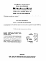
1
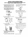
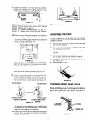
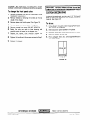
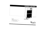
Installation
for your
Instructions
new
undercounter
KCC-151 COMPACTOR
BEFORE YOU USE YOUR COMPACTOR
Be sure
functton
your compactor
and protection
IS properly
Installed
of the compactor.
in an appropriate
level
area
. . .
and a place
suitable
for the size,
ELECTRICAL REQUIREMENTS
Observe All Governing
Codes and Ordinances
A 120.Volt,
60 Hz. AC only. 15.Ampere
fused electrrcal
supply IS required
(Time delay fuse or circuit breaker is
recommended
) It is recommended
that a separate circuit servrng only thus appltance
be provided
DO NOT use
an extensron
cord.
RECOMMENDED
GROUNDING
DO NOT, UNDER ANY CIRCUMSTANCES,
REMOVE
THE POWER
SUPPLY
CORD
GROUND PRONG.
For your personal safety, this appliance must be grounded
This appliance
IS equrpped with a power supply cord
havtng
a 3-prong
grounding
plug To mlnimlze
possble
shock hazard, the cord must be plugged
Into a matlng 3prong
grounding
type
wall
receptacle,
grounded
In
accordance
with
the Natlonal
ElectrIcal
Code and local
codes and ordinances
If a mattng wall receptacle
IS not
avallable.
It IS the personal
responslbllity
and obligation
of
the customer
to have a properly
grounded
3-prong
wall
receptacle
Installed
by a quaIlfled
electrIcIan.
See Figure 1
METHOD
&PRONG
GROUNOING TYPE
WALL RECEPTACLE
POWER SUPPLY
FJGUREI
-lMPORlANTDO NOT REMOVE THIS INSTRUCTION SHEET UNTIL READY FOR INSTALLATION.
AFTER COMPLETINGTHE IMSTALIATION. SAVE THESEINSTRUCTIONSFOR FUTUREUSE.
INSTALLATION
BEFORE
INSTRUCTIONS
YOU BEGIN, READ THE FOLLOWING
INSTRUCTIONS
COMPLETELY
CAREFULLY. THEY WILL SIMPLIFY THE INSTALLATION.
1.
After removing
the shipping
carton, be sure to remove
all protective
packaging
materials
such as tape and
shipping
pads. Put extra key-knob
In a safe place
Waxy residue
from protective
shipping
material
may
be removed
from compactor
with a mild solution
of
liquid household
cleaner
and water.
2.
Your compactor
is designed
for recessed
installation.
A six (6) inch clearance
from the right edge of the
drawer front is desirable
for added convenience
in bag
removal.
Also allow twenty-three
(23) Inches in front
of the appliance
for drawer
removal.
See Figure 3.
COMPACTOR
the umt on either of Its sides on the corner posts. The
corner
posts will protect the finish of the compactor
and the floor
See Figure 8. NOTE: Do not truck or
handle
by console.
FIGURE 8
Remove
bottom
\\I
l&l
AND
7.
WALL OR
OTHER
OBJECTS
the cardboard
See Figure 8
shipplng
pad located
on the
Stand compactor
upright
A grounded
receptacle
should be located
18” (mln )
from the floor and in the center of the opening.
See
Fioure 9
u
2-J”
\\
=a
6,,
FIGURE 3
3.
The compactor’s
overall
dlmenslons
l/16”
(min.), Depth 24”. Width 15”.
opening
to fit. See Fi.qure 4.
are Height 34.
Select a cabinet
FIGURE 9
8.
Before moving the compactor
Into posItion,
measure
the cabinet
opening
as shown
In Figure
70 To
determIne
If height adjustmenr
IS required.
see steps
9 and 10 below
-CABINET
FIGURE 10
MIN
FIGURE 4
4.
9.
Remove
drawer
as shown
Grip handle
and raise front of drawer
uri!!! ,I
a
clears stops
See Figure 5
b.
Grasp side ridges of !he drawer
and lift drawr>r
out See Flgure 6.
10.
5.
6.
The rear wheels
mlnlmgm
cabinet
(posItIon
A) To
compactor
to one
or a screwdrtver
CAUTION:
not drop
\
FIGURE 5
of your compactor
are preset for a
opening
of 34-l ‘8” to 34-l 14”
adjust for higher
openings.
t:ll the
side and support with a corner post
handle
Use care so that
on your hand.
A
FIGURE 6
“,:
w
FIGURE 11
posts
or other
protective
rug) on the floor, then lay
Repeat
2
the
compactor
To adjust the height. remove screw from posltton
In Figure
11. Move
the rear wheel
and screw
posltlon
“B or C”,
34-l/4”
to 34.1,*2”
use position
“B”
34-l/2”
to 34.3/4”
use posltion
“C”
Remove any materials
that are shipped In the drawer
Some models have a literature
storage compartment
located inside the front panel. See Figure 9. DO NOT
REMOVE
THE BAG.
Lay two
carton
corner
material
(such as a throw
OPENING
for
other
rear
wheel
does
A”
to
11.
Loosen
the screws
In the top retaining
brackets.
Rotate
the brackets
from shipping
posrtion
to the
install
position.
Retighten.
See Figure
12.
/qziJYqr
C
FIGURE 15
FIGURE 12
NOTE:
cabinets.
brackets.
Position
Position
12.
15.
Position
“A’‘-Compactor
frame willbe flush with
Remove
cabinet
mount
screws
from retaining
Save for use in step 13.
“B”-Midpoint
between
position
“A” and “C. ”
“C”--Drawer
front will be flush with cabinets.
When moving or lifting the compactor,
protect
and cushion
your hand.
use a glove
In some
covering.
changed
13.
front
of
untrl the
compactor
wrth the cabinet
cord Into a properly grounded
1, 2 and 9.
TOE PLATE
installations,
the toe plate may rub
If this occurs,
the toe plate clearance
as follows:
the floor
may be
1.
Determine
the amount of interference
with the floor covering.
2.
Remove the drawer
from the unrt. (Refer
the Installation
Instructions.)
3.
Lay drawer
the floor.
4.
With a ruler and a pencrl or chalk, draw a line where
the toe plate interferes
with the.floor
covering.
5.
Use a pair of scrssors
See Figure
16.
6.
Replace
FIGURE 13
Lrft the
openrng
the drawer.
ADJUSTABLE
to
To prevent
damage to floor covering,
do not allow the
rear frame of the compactor
to touch the floor when
lrftrng or rolling.
(See Figure
13.)
Alrgn the rear of the
openrng
Plug the power
receptacle.
See Frgures
Replace
so the front
drawer
panel
faces
and cut toe plate
of the toe plate
to Step
upward.
along
3 of
Protect
this line.
In unit
the compactor
and roll Into the
retarnrng
brackets
stop the unrt
Fasten the retarnrng
counter
top wrth the
clip for fastenrng
to
mountrng
method
IS
brackets
to the undersrde
of the
screws
provided
Use auxiliary
cabrnet front when counter
fop
not permissible
See Figure
14.
RETAINER BRACKET
FIGURE 16
CHANGING
RETAINER BRACKET
\
FRONT PANEL COLOR
/
During
installation,
or in the future,
you may wish to
change the front panel color. Your compactor
has an extra
panel,
which
offers
four color options.
See detail
of
assembly
in Figure
17.
MOUNTING
COUNTER TOP MOUNTING
SCREW
Al TEERNATE
CABINET FRONT
MOUN TIMING
FIGURE 14
COLOR PANELS
Lift the front of the compactor
until it is parallel with
the cabinet
front. Place a screwdriver
or other wedge
under the front edge of the compactor.
14.
Loosen
screws).
screws.
DRAWER TRIM
the screws to the front levelers (do not remove
Pivot the levelers
to the floor and retighten
See Figure
15.
FIGURE 17
3
CAUTION:
The panels have cut metal edges. Handle
carefully to avold cutr to hands and scratcher on panela.
To change
1.
the front panel color:
Remove the drawer from
Installation
Instructions.)
the unit.
CUSTOM
Remove
handle
by removing
inside of the drawer.
3.
Remove
spacer
and
inside
panel.
See
4.
Remove
spacer
and center
panel
if supplied.
5.
Remove
outside
6.
Select
carefully
7.
Replace
remaining
panel.
screws
at the
Figure
the handle
9.
Replace
the drawer
with
the screws
replace
inside.
removed
In place of the panel pack, you may use a l/4”
panel to match your cabinets
or other suitable
material.
See Figure
18.
thick wood
decorative
To do so:
DO NOT SCRATCH.
the
spacer,
then
carefully
panels and spacers
on the
Replace
above.
top
16.
the color
you wish
to have showing
push the panel in the drawer
trim
8.
DECORATING
(See Step 4 of the
2.
front
the
REPLACEHANDLE BEFOREOPERATlNG(
kiiiiik
COMPACTORTO AVOID INJURY FROM MOVING PARTS.
and
1.
Follow Steps
Also remove
2.
Slide
1 through 6 under
all cardboard.
decorative
panel
3.
Remount
4.
Slide
handle
with
5.
Paint, wallpaper,
fabric,
one of the panels
between
the screws
Changing
trim
Panel
Color.
pieces.
previously
removed.
the
In Step 2
the drawer
into
the
unit.
etc., can be applied
directly
T
22-15/16’
-M-5/6’;
FIGURE 18
KITCHENAID
FORM 14736 (12-83)
DIVISION
TROY,
OHIO
45374
Part No. 780521
to