1
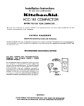
Part No 759105-u
--.
I
__.
Ice Maker
Before you start...
Check
the locatIon
where
the ice make1
WIII be installed
The location
must
provide.
- Easy access
to
electrrclty
and
draInage
lines
. Protection
from wind. weather.
drIppIng
or sprayng
water,
and other
harmful
elements
l Protection
from cold temperatures
to
prevent
the water
inlet valve
and
drain from freezing.
. Good
ventllatlo”
and unobstructed
airflow
to the front of the ice maker
l Room
to fully open the ice maker
door
l Room
to move the cabinet
forward
for
servicing,
of necessary
The unit may be enclosed
around
the
sides, top and rear of ice maker
water.
Proper lnstallotlon
IS your responslbillty
Make
sure you have
everything
necessary
for correct
lnstallat~on
It
IS the customer’s
responslblllty
to
contact
a quaIlfled
rnstaller
to assure that the plumbing
and electrlcal lnstallatlons
are adeauate
and
meet all local codes
and ordinonces
Proper
electrical
supply.
water
supply
lines. and floor drain
or
sump pump
must be avaIlable
or
must be Installed.
as speclfled.
wIthin
the shaded
area
(See
“ElectrIcal
‘Watery.
and
‘Drain
requirements’
sectIons.)
Plumbing
and wrrlng
should
not cross I” front
of the ice maker
motor
Wlrlng
should
not pass through
the drain
Protection
ore0
Important:
ing codes
Electrical
‘ElectrIcal
Observe all governand ordinances.
ground
IS required
requirements”
)
Not close in the front of the ice
work
maker. The Ice maker cannot
Do
front
Compliance
with National
Sonatatlon Foundation
standards
requires
that this type of product
be
sealed
to the floor at the bottom
roll I” order to prevent
contamlnatlon from spills or vermin.
Therefore,
we recommend
that when
Installing this product
you seal It to the
floor I” accordance
with those
standards
A silicone-type
sealer
IS
recommended
installations:
Ice makers
installed
I” ships require
a
water
deflector
(avaIlable
from your
local authorized
parts distributor).
The deflector
keeps the water
that
flows over the evaporator
from
spilling Into the storage
bin area
Install deflector
according
to the
instructions
provided
with the
deflector
kit.
Electrical
requirements
Electrical Shock Hazard
Do Not let electrical wiring and
components contact the drain
hose or any plumbing materials.
Failure to follow these instructions
could result in fire, electrical
shock or other personal injury
T
,-I,24
I;
3’
I-1/2’+
Read and follow the “ElectrIcal
requirements”,
“Water
requirements’
and “Drain
requirements”
sectIons
before
lnstalllng
the ice maker
A 120volt.
m-Hz. AC only, 15.
ampere,
fused, electrical
supply
is
required.
Time-delay
fuse or clrcurt
breaker is recommended
Panel A
recommended
clrcult
serving
be provided
that a separate
only this appliance
It is
Temporary
It the personal
responsrbllIty
and
obligation
of the customer
to
contact
a qualified
electrician
to
assure that the electrlcal
installation
1s adequate
and in conformance
with the National
ElectrIcal
Code
ANSI/NFPA
70 latest edItion.
and all
local codes
and ordinances
Recommended
method
Electrical Shock Hazard
. Electrical QrOUnd is requlred on
1 this appli{nce.
1
l Check
wrth a aualified
electrician if you are In doubt as
to whether the appliance Is
properly grounded. Do Not
modify or remove the power
supply cord plug. If it will not fit
the outlet, h&e-a proper outlet
Installed by a qualified
electrlcian.
l
Improper connection of the
equipment-grounding
conductor can result in a risk of
electrical shock.
l
Do Not use an extension cord
with this appliance.
l
Do Not have a fuse in the neutral
or grounding circuit.
l
Do Not connect to electrical
supply until appliance is
permanently grounded.
Failure to follow these instructions
could result in a fire, electrical
shock, or other personal inJury.
55°F or
operate
between
34.13132’
helghl
Figure 1
Shipboard
Do Not store or
Drain system requires either a gravity.
floor-drain
system or a drain pump
(see
“Drain requlrements~)
to lift the water
to
an exlstlng
drain
A l-114’ mln diameter
standpIpe
or 518” LD mrnrmum
drain
tube to a” open drain IS required
(See
properly
If the airflow
to the
of the Ice maker
is blocked
from weather:
operate
the Ice maker
below
above
110°F
For best results,
the Ice maker
at temperatures
70°F to 90°F
70.latest editIon, and local cobes
ordinances.
(See
Figure
2 )
If a mating
wall receptacle
is not
available,
it IS the personal
responsibility
and obligation
of the
customer
to have a properly
grounded,
3-prong,
wall receptacle
Installed
by a qualified
electrician
Figure 2
method
THIS, HOWEVER, IS NOT
RECOMMENDED.
If this is done, you must connect
grounding
For your personal
safety,
this
appliance
must be grounded.
This
appliance
IS equipped
with a power
supply
cord having
a 3-prong,
grounding
plug.
To mlnimlze
possible
shock hazard.
the cord must be
plugged
Into a mating.
3-prong,
grounding-type
wall receptacle,
grounded
1” accordance
with the
NatIonal
Electrical
Code
ANSliNFPA
and
grounding
If changing
and properly
grounding
the wall receptacle
IS lmposslble
and
where
local codes
permit
(consult
your electrIcal
inspector),
a
temporary
adapter
may be plugged
into the exlstlna.
2-prona.
wall
receptacle
to&&
with the
3-prong.
power
supply
cord
separate,
copper,
grounding
wire
(No 18 minimum)
to a grounded,
cold water
pipe’
by means
of a
clamp
and then to the external
Do
grounding
connector
screw
o
Not
connect to a gas supply pipe or hot
water pipe. (See Figure 3.)
Water
requirements
The cold water
requires
l/4.-0
tubing.
NOTE:
line to the ice maker
D. soft copper
A threaded
compression
fitting to
connect
the water
line to the inlet
valve
is I” the parts bag
Do Not discard shunt. The shunt
must be reattached to the ice
maker when the Ice maker is
operated without a drain pump.
See Installation Instructions
included with drain pump.
Install a shut-off valve in the water
lhe where It can be easy to access
9
Drain
requirements
This appliance
is equipped
with
gravity
drain and a 4’.long.
5/a’- 0.D
rubber,
drain tube
Recommended
easily
Alternate
method
Ii a drain connection directly below
the drain tube outlet Is not available.
1. Follow steps 1 through
10 of the
Snow start .” section
2. Install the drain oumo
on the floor
near the center
of the rear
wall of the cabinet
opening.
The
side of drain pump
with the
discharge
tube should
face the rear
of the obenlng
3 Remove
the rubber
drain hose
and connect
the bin drain directly
to
the pump
using 5/B” I D. plastic
hose.
(See Figure 4.)
4 Run pump
drain hose to drain
(See Figure 4.)
5 Run the power
supply
cord from
the puma
throuah
the hole I” the
rear’of
the ice Gaker.
(See Figure 4.)
n
Figure 6
7. Reattach
maker
with
the air grille to the
the two screws
Ice
Now start...
1
H
a drain pump
(Part No EKDPB) WIII
need to be installed.
The drain
pump,
available
from your local
authorized
parts distributor.
lifts water
to an avaIlable
drain.
Electrical Shock Hazard
Disconnect power supply.
Failure to do so could result in
electrical shock or personal
injury.
a shutoff
valve
I” the
line where
It can be
Flush the water
line into a
bucket
to get rid of any
particles
that may clog the Inlet
valve.
Turn the shutoff
valve to the
“off” posltion.
method
It may be desirable
to Insulate
the
drain line up to the drain inlet to
minimize
condensation
on the drain
tube
Install
water
used
10
a
Install a l-114’ minimum
diameter
standplpe
directly
below
the drain
tube outlet.
(See Panel A for
dimensions
)
n
Carefully
place
side. Open the
Failure to do so could result in
carton
bottom
on Its
flaps
CD
open twnom
2
H
outward.
maker.
3
4.
n
outside
1lOPl
Set carton
upright
four. bottom
flaps
Remove
carton
with all
folded
from Ice
11
n
and follow
Instructions
Panel
B.
Determine
which
type of
drain method
you need
the *Drain
requirements”
for that method
on
Move Ice maker close to
Its final position.
Electrical Shock Hazard
Disconnect power supply.
Failure to do so could result in
electrical shock or personal
Remove
all tape and
packing
material
from the
and InsIde of the ice maker
Remove
parts
package
from
Inside Ice
maker
bin
12
13
1
Plug the electrical
Into the grounded
cord
outlet.
Insert the cold-water
n suoolv
tublna
through
the
hole in the r&r bf the i:e maker
Slide the ice maker
Into place.
Center
the Ice maker
I” the opening.
Remove
the cardboard/hardboard
Y
Remove
the two screws
W attaching
the air grille to the
5
Ice maker.
Remove
the air grille.
Figure 4
6 Remove
the two screws attaching
the afr grille to the ice maker.
Remove
the air grille (See Figure 5 )
6
7
n
Turn the fan by hand to
check
that It moves freely
Slightly
loosen,
but
n
remove,
the thumb
holding
the cutter
grid and
pan in place
8
Figure 5
7 Remove
and save the shunt from
the ice maker
receptacle
Plug the
drain pump,
power
supply
cord into
the receptacle.
(See Figure 6.)
Panel B
Do Not
screws
water
Rough in l/4’-0.D
soft
n copper
tubing
from the cold
PosItion tubing
so
water
supply
line
that It can enter the access
hole
located
I” the rear of the ice maker
cabinet
Place tubing
in the center
of the opening
and allow enough
tubing
so that It extends
beyond
the
cablnet
front when
the icemaker
is
pushed
back Into position
[See
Panel A),
14
Attach
the hose by the
threaded.
compreSSlon
fitting to the ice makers
cold-water
inlet valve.
Bend the cold-water
supply tubing
up toward
the flttlng.
Attach
the cold-water
supply
tubing
Check
for good fit
to the fitting
n
15
Check
the levelness
of the
n ice maker
from front to
The ice
back and side to side
maker
must be level for proper
operation.
Shim the ice maker
with
masonlte
or any hard, permanent
material
so that It is level and held
If local codes
tightly
I” place
require.
seal Ice maker
cabinet
to
floor with an approved
caulking
compound
16
steps
have
Check
that all parts have
n been installed
and that no
were skipped.
Check
that you
all the tools you started
with.
17
Take CI few minutes
to
read the “Ice maker
operation”
section,
Panel C, and
Use and Core Guide to fully
understand
your new ice maker.
Ice maker
operation
n
the
Before running
your rce maker
for the
frrst time, you should
note the
followinQ
* Water
enters only durrng the
defrost
cycle,
so the first harvest
cycle ~111 be completed
without
water
in the system.
l
Water WIII not enter the pump
pan until the freezing
plate gets
cold and the ice maker
begIns
o
harvest
cycle
l
A normal
harvest
cycle takes
between
60 to 120 seconds
to
complete.
However,
do not
expect
Ice until the ice maker
hds been operating
for at least
three hours
- The evaporator
thermostat
opens
when
the evaporator
reaches
the preset temperature
(+lo” to -3°F. depending
on the
thickness
of the ice)
The hot was
solenord
and the water
valve
solenoid
are energized
at this
time, so the pump
motor and fan
motor wrll shut down.
The motors
will reman
off and the solenoids
wrll remain
charged
until the
evaporator
reaches
38°F &2”F)
ago,“.
l
As the temperature
of the room
and water
varies, so will the
amount
of Ice produced.
Hrgher
operating
temperatures
will result
in less ice made
To make the
most ice. set the thickness
control
to produce
l/2’ to 510’ cubes
18
Open
rce maker
door.
n Wash out the interior
of
the bin wtth CI solution
of two
of baking soda and one
tablespoons
quart
of water.
Rinse the bin
thoroughly
with water.
19
If Ice maker
is rnstolled
.
above
2,DBfeet
altitude,
the bin and evaporator
thermostats
will need odjusttng.
Remove
the thermostats
and follow
the drrections
for turning
the altitude
adjustment
screws OS shown
on
each
of the thermostat
labels.
Relnstoll
the thermostats
in the ice
maker.
20
21
turn
w Replace
the
access
grrlle.
Turn on the water
supply
n and check
for leaks Then
on the electrical
supply
Turn the ice maker
control
. knob to the right to the
22
“CLEAN”
position.
Check
that the
pump
motor
is operating
correctly
23
that
the
Turn the control
knob to
. the ‘ON’
position.
Check
condenser
fan is revolving.
4 Break off the ribs on the door
insulation.
5 Slide the wood
door brn panel
the door brn frame
6. Reattach
the handle
with the
24
Let the ice maker
run for
n three hours
When water
flows over the freezing
plate,
check
that it is flowing
evenly
If it IS not, the
ice maker
IS not level and Step 15
should
be repeated.
The bin door
be customized
cabrnets.
and lower panel
con
to match
wood
two
screws.
7. Remove
the two screws at the
bottom
and the two screws at the
top of the lower panel
Remove
the
top of the lower panel
assembly
8 Slide the metal
panel
and the
spacers
out of the lower panel
assembly.
9 Slrde the metal
panel
back Into
the lower panel
assembly
Slide
the wood
panel
in front of the metal
panel.
10. Reattach
the tow of the pore
with the two screws’and
replace
the
two screws at the bottom
of the
assembly.
How your ice
maker works:
When the ice maker is turned
to “ON”:
- Compressor
and condenser
fans
run
l
Water
pump
crrculates
water
- Cutter
grad becomes
worm to
touch.
When the ice slab reaches
desired thickness:
the
. Harvest
cycle
begins
(Normal
harvest
cycle takes 60 to 120
seconds.)
l
Evaporator
thermostat
IS
satisfied.
. Compressor
keeps running.
but
the condenser
fan will stop
turning
or turn very slowly
. Water
pump
stops
and the water
. Hot QOS solenoid
inlet valve
open.
. Excess water
IS flushed
out of the
drain pan.
. Cutter
grid remalns
worm to
touch.
To change the
bin door and
lower panel
Important:
Ice maker must run for three hours
before you may expecl ice.
Into
After the slab is released:
* Cycle
l Cuthng
begins
oQaIn.
process
begins
When the storage
bin is filled:
Bin thermostat
opens.
. Cutter
grid remains
on.
l
Important:
Do Not adjust the thickness setting
until Ice maker has run for 24
hours.
Things to
remember
25
Continue
to let the ice
n
maker
run for 24 hours.
Check
to see if cubes are the
desrred
thickness
and, if necessary.
odiust the thickness
control.
26
If tnstalling
decorative
wood
panels
on the
door and lower panel,
follow the
change
the bin door and lower
panelinstructlons.
W
Personal InJury Hazard
Handle metal edges carefully.
Cut metal edges may cause
personal ln]ury or damage to
other materials.
“To
1 Cut panels
using the specified
dimensions.
Make sure wood
groin
matches
thedrrectlon
of the coblnet
wood
grain.
The Ice maker Is subject to some
humldlty. Cover both sides and
edges of the wood panels with
molsture-reslstant
sealer.
\ Congratulations!
w
Keep lnstallutlon
Panel C
lnstructlons
The ice maker
will automatically
continue
to harvest
Ice until the
storage
bin IS full The Ice maker
wrll shut down
when
the ice I” the
storage
bin touches
the bin
thermostat
well.
It will begin
harvesting
ice agoln
when
Ice IS
removed
from the brn.
l
The storage
bin is not refrigerated
so there will be some melting.
This
will vary with the temperature
of
the room where
the Ice maker
is
located
l
The ice maker
must have good
ventllatron
to work properly.
Do
Not block the front of the Ice
maker
Keep the front air grille
and condenser
clean.
- The water
system.
Including
the
filter screen
in the water
solenord
valve,
needs to be cleaned
perrodrcally
for good
circulatrOn.
lnstructrons
for cleaning
the water
system are located
on the inner
door panel
l
J
2. Open the bin door and remove
the two screws holding
the handle
the top of the door.
Remove
the
handle.
3. Slrde the metal
panel
out of the
brn door.
to
Wiring diagram
If you need
assistance...
The compressor
will remain
running
until the bin
thermostat
becomes
satisfied
and opens up. This
de-energizes
all the system except
for the
transformer.
cutter grid. and glacial
Ice water
pump
This appliance
operates
at 115 volts, except
for the
cutter Qrld circuit and glaclol
ice water
pump.
which
operate
at 8 5 volts at 1 amp
During normal business hours, the
Whirlpool COOL-LINE” Service will
answer any questions about
operating
your ice maker not
covered in the Installation
Instructions. The Whirlpool
COOL-LINE” Service telephone
number is (800) 253-1301. DICI just as
you normally dial long distance the call ISfree. When you call, you
will need the ice maker model
number and serial number. Both
numbers can be found on the serial/
ratrng plate located behind the bin
door on the frame.
In the event that your Whirlpool
appliance
should need sewice, call
the dealer from whom you
purchased
the appliance
or a
Whirlpool franchised sewice
company.
The Whirlpool
COOL-LINE” Service can also provide
you with the names of your nearest
Whirlpool service outlet
Cubelet
cuHer
grid
Cube
cuHer
grid 1
If ice maker
does not
operate...
Check that the circuit breaker is not
trapped or the fuse blown. A more
detailed, troubleshooting
checklist is
orovided in the Use and Care Guide.
PartNo
759105-U
0 Whirlpool
Corp.
1990
Prepared
by Whirlpool
Corporation,
Benton
Harbor,
Michlgon
49022
Printed
In U.S.A