1
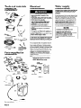
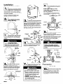
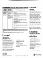
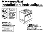
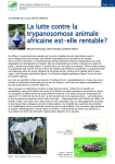
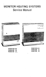
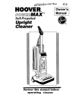
Installation Instructions/Use and Care Guide
Hot Water
Dispenser
Important:
Read and save
these instructions.
IMPORTANT:
Installer: Leave Installation Instructions with homeowner.
Homeowner:
Keep Installation Instructions for future
reference.
Save Installation Instructions for local electrical
inspector’s use.
Part No. 3184330
Before you start...
Check location where hot water dispenser will be
installed. Proper installation is your responsibility.
Make sure you have everything necessary for
correct installation. It is the responsibility of the
installer to comply with installation specifications
provided and with state and local plumbing codes.
Electrical Shock Hazard
Special care must be taken when drilling
holes into walls or water pipes. Electrical
wires may be concealed behind the wall
covering or water may remain in pipes.
Failure to follow this instruction could result
in personal injury or death.
Personal Injury Hazard
Install faucet with lever to the side or behind
spout.
Failure to do so may result in hot water
scalding hand when operating lever.
Faucet mounting: requires a 1-l/l 6” to l-3/8”
diameter opening in sink or countertop for
mounting hot water dispenser faucet. Faucet can
be installed in place of sink sprayer. For other
installations, contact a qualified installer for best
procedure to drill a hole through your type of sink
or countertop. Thickness of sink or countertop hole
must not exceed 3/4”.
Dimensions
NOTE:
This hot water dispenser is Not a water
purifier. Some installations
may require a
filter (such as charcoal) for increased
satisfaction.
shown must be used.
Property/Product
Damage
Contact a qualified installer or licensed
plumber for the best procedure for cutting
a faucet opening in your type of sink or
countertop.
l Plumbing
connections
must comply with
all sanitary, safety and plumbing codes.
l Do Not store
or operate hot water
dispenser below 32°F.
l Do Not use pipe sealing
compounds. They
may get inside dispenser and cause an
unpleasant taste or smell.
l Dispenser
must be filled with water and
thermostat turned to “OFF” position
before connecting to electrical power
supplyFailure to follow these instructions
may
result in water damage to property or
permanent product damage not covered by
the warranty.
Proper cold water supply connection must be
available. (See “Water supply requirements,”
Panel B.)
l
Use saddle tapping valve supplied. Saddle
tapping valve is designed for use with 3/8” to l3/8” outer dimension (O.D.), soft copper tubing
(plain or chrome plated) or rigid metal pipe. Do Not
use the saddle valve with flexible ribbed tubing.
(See “Water supply requirements,” Panels B.)
Flexible ribbed tubing requires special connecting
hardware available from your local plumbing
supply.
Grounded electrical outlet is required. (See
“Electrical requirements,” Panel B.) Outlet should
be located for easy connection to hot water
dispenser. The outlet should be within 30” of hot
water dispenser tank.
Top view
Water connections use compression fittings which
do Not require sealing compounds to keep them
from leaking.
lever
install faucet with lever to
the side or behind spout.
Important: Observe all governing
ordinances.
codes and
Faucet
mounted in
existing hc
- )le in
sink.
sink or countertop
hole
Cold water line
30” max.-electrical
outlet to hot water
dispenser tank.
Panel A
.-
spout
Tools and materials
needed for
installation:
Electrical Shock Hazard
l Electrical
ground is required on this
appliance.
l If cold
water pipe is interrupted by plastic,
non-metallic
gaskets or other insulating
materials, Do Not use for grounding.
l Do Not ground
to a gas pipe.
l Do Not modify
the power supply cord
plug. If it does not fit the outlet, have a
proper outlet installed by a qualified
electrician.
l Do Not have a fuse in the neutral
or
grounding circuit. A fuse in the neutral or
grounding circuit could result in electrical
shock
l Do Not use an extension
cord with this
appliance.
l Check with
a qualified electrician if you are
in doubt as to whether this appliance is
properly grounded.
Failure to follow these instructions
could
result in serious injury or death.
tubing cutter
bucket or pan
9/l 6”, 7/l 6” and Ii2
open-end wrenches
If codes permit and a separate grounding wire
is used, it is recommended that a qualified
electrician determine that the grounding
path
is adequate.
l/4” O.D. copper
tubing
2 mounting bracket
screws (and 2 plastic
anchors if attaching
to dry wall)
pencil
Parts supplied for
installation:
4
saddle
tank bracket
For your personal safety, this appliance must be
grounded. This appliance is equipped with a
power supply cord having a 3-prong grounding
plug. To minimize possible shock hazard, the cord
must be plugged into a mating 3-prong groundingtype wall receptacle, grounded in accordance with
National Electrical Code, ANSVNFPA 70-latest
edition* and all local codes and ordinances. (See
Figure 1.) If a mating wall receptacle is not
available, it is the personal responsibility and
obligation of the customer to have a properly
grounded 3-prong wall receptacle installed by a
qualified electrician.
Copies of the standard listed may be obtained
from:
l
National Fire Protection
Batterymarch Park
Quincy, Massachusetts
3-pron
groun ci!mg-type
wall receptacle
, brass insert
8
-62
2 square nuts
cord
Figure 1
faucet assembly
Remove parts from packages.
parts were included.
Panel B
Water supply
requirements
Electrical
requirements
Check that all
Association
02269
Important: If local codes do Not permit the use
of saddle valves, special feed valves can be
obtained from your local plumbing supply
distributor.
If local codes permit, the hot water dispenser feed
line should be connected to the cold water supply
line using a saddle tapping valve. The saddle
tapping valve supplied is designed for use with
3/8” to l-318” outer dimension (O.D.), soft copper
supply tubing (plain or chrome plated) and rigid
metal pipe. Do Not use saddle valve with
flexible ribbed supply tubing. Flexible ribbed
supply tubing has a thin wall thickness and
requires special connection hardware, available
from your local plumbing supply distributor.
NOTE:
Connection to hot water line is not
recommended.
Energy will be wasted in
heating the water twice and the
magnesium rod used in household heating
may produce a “rotten egg” taste.
If this unit is replacing a hot water
dispenser connected to a hot water
supply, the existing connection may be
used.
Installation
Turn off main water supply. Turn on
sink cold water faucet and allow all
water to drain from line. Turn off
faucet.
With hot water dispenser in kitchen.
I
1
Determine the best faucet mounting
position that will allow faucet spout to
empty into sink. Check below sink to
assure that reinforcing ribs, support brackets or
cabinet construction will not interfere with faucet
mounting. Knock out plug from hole in sink or cut a
hole in sink or countertop.
If water supply
If water supply line is rigid metal, use a
grounded electric drill or hand drill to drill a l/4”
hole in the cold water line.
NOTE: Flexible ribbed tubing requires special
connecting hardware available from your local
plumbing supply.
NOTE: It is recommended that only a licensed
plumber or professional
installer cut an
opening in the sink or countertop.
I
When unpacking faucet, Do Not
remove ureen tape from faucet
j tubing oFtank tubing.
j
is copper, go to Step 9.
1
bracket
Position tank vertically beneath faucet
I so that clear tubina from faucet
u
reaches center cobper tubing on tank,
and tank touches wall. Use a pencil to mark on the
wall where the top of tank needs to be located. Set
tank aside. Mark a second line 2-l/4” below the
line. Position mounting bracket on wall so that
bottom of mounting bracket is even with the lower
line. Use two screws (and plastic anchors if
attaching to dry wall) to fasten mounting bracket to
wall. Hang tank on bracket.
compression
union\
Lay faucet on flat surface with coiled
tubing facing up. Using one hand to
hold tubinn iust below faucet, carefullv
straighten tubing with other hand. Slide gasket z
over tubing so that gasket is seated under base
of faucet.
Install faucet with lever to the side or
Failure to do so may result in hot water
scalding hand when operating lever.
I
W’
green
We
T
19 I
n
u
Turn saddle valve handle so piercing
lance does not protrude.
Put seal on saddle valve and position assembly on
vertical, cold water supply line.
compression
DO Not lengthen, twist or
tightly bend tubes.
Do Not remove green tags.
I
Use a compression union to connect
the longer, l/4” tubing from the faucet
I
to the back tubina in the top of the
tank (both are marked with green tape): Faucet
tubing may be shortened if necessary.
lever to the
side or
behind spout
sjnk
f#
View from top
Align bottom clamp holes with holes in top clamp.
Insert clamp screws. Attach one square nut to end
of each clamo screw. Tiahten nuts evenlv and
firmlv, keep& bracketstarallel.
Do Notovet%ghtdn clamp screws, copper tubing
could be crushed.
Product Damage
Do Not use pipe sealing compounds.
Pipe sealing compounds may get inside
dispenser and cause an unpleasant taste
or smell.
J
.
outlet
green
We
n
7
-
\’
//
IIt-
Hold gasket in position and insert
tubing through gasket, then into
mountina hole. From under
sink/cabinet, slide w&her then wing nut with flat
side facing up over tubing. Check that lever is
positioned to the side or behind spout and that
spout is positioned to empty into sink. Tighten
wing nut by hand until faucet is securely in
position.
Top view
)-.
0
0
0
0
.N
n
I
spout
Panel C
Install faucet with
lever to the side
or behind spout
180” .\
\
.
lever
\
\
clear tubing
7
H
fl
Connect clear tubing from faucet to
middle tank tube using clamp. Clear
tubing may be shortened, if
necessary.
Electrical Shock Hazard
Some water may remain in water supply
pipe:
l
If an electric drill is used, it must be
properly grounded to prevent severe or
lethal shock if water should enter drill.
Use only an electric drill with a 3-wire
cord connected to a grounded
receptacle.
l Check
with a qualified electrician if you
are in doubt as to whether your electric
drill is properly grounded.
Failure to follow these instructions
could
result in personal injury or death.
- 4
Piercing lance in
closed position.
Assembly fits 318” through l-318”
O.D. copper or rigid metal line.
View from top
Slide brass sleeve into copper tubing
fitting; use plastic sleeve if water
u
sup&y line-is not copper. Attach
fitting to saddle valve outlet. Connect l/4” O.D.
copper tubing (not supplied) to tubing fitting.
Do not seal the connections
compounds.
with sealing
Numbers
correspond
to steps.
green tape
tubing
faiket
I4n
Push or pull faucet lever to open
position. Hold lever in open position
I
1 until tank is full (approximately 1
len tank is full. water will flow from
faucet spout. Release lever to close faucet. Check
for leaks.
BIcm
saddle
valve
II
111I
Turn saddle valve handle clockwise
until lance pierces soft copper tubing
u
and valve is firmly seated: The valve
is now in the closed position. Place a bucket
under open end of water supply line. Turn on main
water supply valve to pressurize cold water line.
Check for leaks. Use a wrench to tighten nut/seal
around valve stem.
minute).
’
Open saddle valve and flush line into
bucket to remove any foreign
material that may have been trapped
n the suppl lY line during saddle valve installation.
Close sadd le valve.
Panel D
rl13
Connect water supply line from
saddle valve to shorter copper tubing
12
from the faucet using the
compression union. Open saddle valve.
n
Product Damage
Do Not remove internal stainless steel
filter screen from the compression
fitting.
Failure to follow this instruction could
result in damage to the valve.
Fill tank with water and turn thermostat to
“OFF” position before plugging hot water
dispenser into power supply.
Failure to do so could cause hot water
dispenser heater to overheat resulting in
an unpleasant taste, black specks in water,
and permanent damage to the heater
seals.
115I
Turn thermostat knob counterclockwise to “OFF’ position. Plug
1
1 power supply cord into properly
grounded outlet. Turn thermostat knob clockwise
to highest position. Water in tank will reach
maximum temperature in approximately 15
minutes and dispenser will be ready for use. Lower
temperature setting if you notice vapor or hear
boiling noise.
NOTE: Thermostat controls tank heater, not water
delivery. Rotate thermostat knob clockwise to raise
water temperature; counterclockwise to lower
water temperature.
=
To get the most efficient use from
your new hot water dispenser, read
the Use & Care Information. Keep
Ins talla tion lnstruc tions4Jse & Care
Guide close to hot water dispenser
for easy reference.
Use and care
information
For short periods (2-30 days) of nonuse:
Set the hot water dispenser thermostat to the
“OFF’ position to conserve energy.
If you have very hard water, it may be necessary
to occasionally clean the faucet screen to remove
sediment buildup.
Your hot water dispenser uses a heating element
to warm water in the tank to approximately 190°F
when the temperature control is turned to the
highest position. You can draw approximately 2
quarts of hot water at a time. As hot water is
drawn from the tank, it refills with cold water, which
is then heated. It takes approximately 15 minutes
for a tank of cold water to heat to the maximum
temperature.
l
l
l
l
l
Personal Injury Hazard
Check that lever is to the side or behind
faucet spout before using hot water
dispenser.
Do Not reach into or splash hot water on
skin.
Do Not let children operate hot water
dispenser.
Do Not leave children or infants
unattended near hot water dispenser.
Do Not use hot water from dispenser for
bathing children, infants or pets.
Water from hot water dispenser can reach
temperatures of approximately
190°F.
Failure to follow these instructions
may
result in scalding or burns from hot water.
To get hot water from the tank:
Push or pull faucet lever.
To stop water flow from faucet:
Release faucet lever and let it return to the vertical
position.
Ways you can use your hot water
dispenser:
’
Your hot water dispenser water has many uses,
including:
l To prepare instant foods and drinks that require
190°F maximum water for preparation (such as
instant coffee, tea, hot chocolate, bouillon, soup,
instant cereal, instant mashed potatoes, frosting
mix, etc.).
l To get a fast start on cooking foods that require
boiling (such as hard boiled eggs, fresh or frozen
vegetables, meat cooking in liquid, dried soup,
pasta, rice, hot cereals, packaged dinners with
pasta, rice or potatoes).
l Loosening
jar lids.
l Warming baby bottles.
l Warming
baby food.
l Filling hot water bottles.
l Peeling tomatoes
or peaches.
l Dissolving
gelatin.
l Thawing
frozen foods.
l Preparing
vegetables for canning.
To remove the faucet screen:
1. Set hot water dispenser thermostat to “OFF.”
2. Hold lever down and drain hot water from tank.
Release lever.
3. Unscrew nozzle from faucet spout.
4. Remove screen and flow director from inside
nozzle.
To clean the screen and flow director:
1. Use a small brush and vinegar to remove
deposits.
2. If deposits have hardened, soak screen and
flow director in vinegar for l-2 hours. Then use
brush to clean.
To replace faucet screen:
1. Insert flow director into nozzle. Then insert
screen.
2. Position nozzle on end of faucet spout and
carefully tighten by hand.
NOTE: Nozzle must be fully tightened for screen
and flow director to be properly seated and for
nozzle not to leak.
3. Check that faucet spout is positioned away from
faucet lever. Hold lever down and check for
leaks at nozzle. If nozzle leaks, remove nozzle
and check that screen and flow director are
properly positioned. Replace nozzle and check
for leaks again.
4. Set hot water dispenser thermostat to “HIGH.”
On average, you will use your hot water dispenser
to heat 7 to 8 cups of water per day. This uses
only 19 kilowatt-hours of energy per month. So it is
Not necessary to turn off the hot water dispenser
each night to conserve energy.
However, if the hot water dispenser will not be
used for an extended period of time, follow these
instructions -
Problem
The water temperature is controlled by a
thermostat on the tank. The thermostat has infinite
settings between “OFF’ and “HIGH” and can be
adjusted by rotating the thermostat knob clockwise
for a higher temperature; counter-clockwise for a
lower temperature.
When the thermostat knob is turned to the “OFF’
position, the hot water dispenser will not heat the
water. When the thermostat knob is turned to the
“HIGH” position, the water will heat to
approximately 190°F.
It is recommended that the thermostat be set to
the “HIGH” position for the best performance.
However, under certain conditions, it is possible
that you will see vapor coming out of the faucet or
hear a boiling noise when the thermostat is set to
“HIGH.” If this occurs, lower the thermostat setting
to a position that eliminates the vapor or noise.
Panel E
For long periods of nonuse, seasonal storage
or protection from freezing:
1. Turn hot water dispenser thermostat to the
“OFF’ position.
2. Unplug hot water dispenser power supply cord.
3. Hold down faucet lever and run water until
water is cold.
4. Turn saddle valve handle clockwise to turn off
water supply.
5. Place a 3-quart minimum container under the
drain plug at the bottom of the tank.
6. Remove drain plug with a 9116” wrench and
allow all water to drain from tank.
6. Replace plug, but do Not overtighten.
drain
plug
Product Damage
Fill tank with water and turn thermostat to
“OFF” position before plugging hot water
dispenser into power supply.
Failure to do so could cause hot water
dispenser heater to overheat resulting in an
unpleasant taste, black specks in water,
and permanent damage to the heater seals.
1. Turn saddle valve handle counterclockwise to
open water supply line.
2. Hold down faucet lever until tank is full
(approximately 1 minute). When tank is full,
water will flow from faucet spout. Release lever.
Check for leaks.
3. Check that hot water dispenser thermostat is
set to “OFF’ position.
4. Plug power supply cord into properly grounded
outlet.
5. Set thermostat to “HIGH” position. Water in tank
will reach maximum temperature in
approximately 15 minutes and dispenser will be
ready for use.
Solution
Water is not hot.
A. Check that
B. Check that
C. Check that
D. Cold water
temperature
Vapor appears or dispenser makes
boiling water noises.
Adjust hot water dispenser thermostat to a lower setting that eliminates
the vapor or noise.
Hot water drips or sputters from
faucet.
A. Check that tubing is not bent or kinked.
6. Adjust hot water dispenser thermostat to a lower setting that
eliminates the drips/sputters.
C. Checkthat nozzle screen is not clogged. See “Maintaining your hot
water dispenser,” Panel E.
D. Check for proper installation of copper tubing from faucet to storage
tank and from faucet to cold water line. See Steps 6-13, Panels C
and D.
Water does not flow from faucet.
Check that water supply valve is open.
Leaking saddle vatve.
Tighten saddte valve clamp screws evenly and firmly, keeping both
halves of bracket parallel. Do Not deform tubing.
Water has a “rotten egg” taste.
A. Hot water dispenser is attached to hot water line. Attach to cold water
line.
B. Install a water filtration system on cold water line to dispenser.
the circuit breaker is not tripped or the house fuse blown.
power supply cord is plugged into wall receptacle.
hot water dispenser thermostat is set to “HIGH” position.
in tank is stiil being heated. Wait 15 minutes and check
again.
Km~he~Aid%stant-Iiot’VVater
LENGTH OF
WARRANTY
ONE YEAR FULL
WARRANTY
FROM DATE OF
INSTALLATION.
KITCHENAID
WILL PAY FOR:
Replacement parts
and repair labor to
correct defects in
materials or
workmanship. Service
must be provided by a
KitchenAid-authorized
servicing outlet.
Dispenser Warranty
KITCHENAID
If you need
service...
WILL NOT PAY FOR:
In the event that your KitchenAid appliance
should need service, call the dealer from whom
you purchased the appliance or a KitchenAidauthorized service company. A KitchenAidauthorized service company is listed in the
Yellow Pages of your telephone directory under
“Appliances - Household - Major - Service or
Repair.” You can also obtain the service
company’s name and telephone number by
dialing, free, within in the continental United
States, the KitchenAid Consumer Assistance
Center telephone number, 1-800-422-l 230. A
special operator will tell you the name and
number of your nearest KitchenAid-authorized
service company.
A. Service calls to:
1.) Correct installation of the Instant-Hot Water Dispenser.
2.) Instruct you how to use the Instant-Hot Water Dispenser.
3.) Replace house fuses, circuit breakers or correct house wiring.
4.) Correct house plumbing.
B. Repairs when Instant Hot Water Dispenser is used in other than
normal home use.
C. Damage resulting from accident, alteration, misuse, abuse,
improper installation or installation not in accordance with local
electrical or plumbing codes,
D. Replacement parts or repair labor costs for units operated outside
the United States.
E. Repairs to parts or systems caused by unauthorized modifications
made to the appliance.
F. Pickup and delivery. This product is designed to be repaired in the
home.
KITCHENAID DOES NOT ASSUME ANY RESPONSIBILITY FOR INCIDENTAL OR CONSEQUENTIAL
DAMAGES. Some states
do not allow the exclusion or limitation of incidental or consequential
damages, so this limitation or exclusion may not apply
to you.
This warranty gives you specific legal rights, and you may have other rights which vary from state to state.
If you need
assistance...
The KitchenAid Consumer Assistance Center will
answer any questions about operating or
maintaining your hot water dispenser not covered
in the Installation Instructions and Use and Care
Guide. The KitchenAid Consumer Assistance
Center is open 24 hours a day, 7 days a week.
Just dial 1-800-422-l 230 - the call is free.
If you are not
satisfied with the
action taken:
l
If you prefer, write to:
Consumer Assistance Center
KitchenAid
P.O. Box 550
St. Joseph, Ml 49085-0558
Please include a daytime phone number in your
correspondence.
When you call, you will need the hot water
dispenser model number and serial number. Both
numbers can be found on the serial/rating plate
located on the hot water dispenser tank.
Part No. 3184330
0 1992 KitchenAid
@ Registered Trademark of KitchenAid
Maintain the quality built into your KitchenAid
appliance - call a KitchenAid-authorized
service
company.
l
l
Prepared bv KitchenAid,
St. Joseph, Michigan 49085
Contact the Major Appliance Consumer Action
Panel (MACAP). MACAP is a group of
independent consumer experts that voices
consumer views at the highest levels of the
major appliance industry.
Contact MACAP only when the dealer,
authorized servicer and KitchenAid have failed
to resolve your problem.
Major Appliance Consumer Action Panel
20 North Wacker Drive
Chicago, IL 60606
MACAP will in turn inform us of your action.
Printed on recycled paper.
Printed in U.S.A.