1
Back
Exit
VEGA LT
INSTALLATION
AND
COMMISSIONING
MANUAL
TM0081
PROPRIETARY RIGHTS NOTICE
The information contained in this manual is the property of Kidde Fire Protection Services Limited and may not
be reproduced or transmitted in any form or by any means, electronic, mechanical, photocopying, recording or
otherwise, nor stored in any retrieval system of any nature without the express written authority of Kidde Fire
Protection Services Limited.
© Copyright 2003 Kidde Fire Protection Services Ltd
TM0081
Page 1 of 51
Issue 1.01
TABLE OF CONTENTS
1.
1.1
1.2
1.3
1.4
2.
3.
3.1
3.2
3.3
3.4
3.5
3.5.1
3.5.2
3.5.3
3.5.4
3.5.6
3.5.7
3.5.8
4.
4.1
5.
5.1
5.2
5.3
5.4
6.
6.1
6.2
6.2
6.3
6.4
6.4.1
6.4.2
6.4.3
7.
8.
9.
9.1
9.2
9.3
9.4
9.5
10.
10.1
10.2
10.3
10.4
10.5
10.5.1
10.5.2
10.5.3
10.6
11.
11.1
11.2
11.3
11.4
11.5
11.5.1
11.5.2
INTRODUCTION ........................................................................................................................................4
DESCRIPTION ...........................................................................................................................................4
ABOUT THIS MANUAL ..............................................................................................................................5
SYSTEM DESIGN ......................................................................................................................................5
ELECTRICAL SAFETY...............................................................................................................................5
GLOSSARY OF TERMS AND ABBREVIATIONS......................................................................................6
INSTALLATION ..........................................................................................................................................7
SYSTEM SCHEMATIC ...............................................................................................................................7
APPROVED CABLES.................................................................................................................................8
INTERNAL CABLE ROUTING....................................................................................................................8
ENCLOSURE MOUNTING .........................................................................................................................9
EXTERNAL CONNECTIONS ...................................................................................................................10
Mains Wiring .............................................................................................................................................10
Detection Loop Wiring...............................................................................................................................10
Sounder Circuit Wiring ..............................................................................................................................12
Auxiliary Output Wiring .............................................................................................................................12
Auxiliary Input Wiring ................................................................................................................................13
Battery Installation ....................................................................................................................................14
Network and Repeater Cable Wiring ........................................................................................................14
ACCESS CONTROL LEVELS..................................................................................................................15
ACCESS INHIBIT KEYSWITCH...............................................................................................................15
CONTROLS AND INDICATION ...............................................................................................................16
PANEL DISPLAY ......................................................................................................................................16
CONTROL BUTTON FUNCTIONS ..........................................................................................................16
STATUS WINDOW INDICATION .............................................................................................................17
LIQUID CRYSTAL DISPLAY LAYOUT.....................................................................................................17
OPERATION.............................................................................................................................................18
STATUS NORMAL ...................................................................................................................................18
GAINING ACCESS TO LEVEL 2 OR 3 ....................................................................................................18
FIRE CONDITION.....................................................................................................................................18
RESETTING THE SYSTEM AFTER A FIRE CONDITION ......................................................................20
FAULT CONDITIONS ...............................................................................................................................20
System Faults ...........................................................................................................................................20
Zone Fault Conditions...............................................................................................................................21
Group Fault Conditions .............................................................................................................................22
PRIORITY ALARM STRUCTURE ............................................................................................................23
FIRE & PLANT ZONE INDICATIONS ......................................................................................................23
MENU STRUCTURE ................................................................................................................................23
MAIN MENU .............................................................................................................................................23
ISOLATE \ DE-ISOLATE MENU...............................................................................................................24
LIST MENU...............................................................................................................................................25
SET MENU ...............................................................................................................................................26
TEST MENU .............................................................................................................................................27
COMMISSIONING ....................................................................................................................................28
SYSTEM CHECKS ...................................................................................................................................28
INITIAL POWER UP .................................................................................................................................28
POWERING DOWN .................................................................................................................................29
CONNECTING THE DETECTION LOOP.................................................................................................29
ADDING OR REMOVING LOOP DEVICES .............................................................................................29
Power Down..............................................................................................................................................29
Processor Restart .....................................................................................................................................30
Auto Learn ................................................................................................................................................30
CONNECTING SOUNDER CIRCUITS.....................................................................................................30
PROGRAMMING STANDARD & CUSTOM FEATURES.........................................................................31
PANEL SET-UP ........................................................................................................................................31
ZONE FIRE INFORMATION ....................................................................................................................32
LOOP DEVICE INFORMATION ...............................................................................................................32
PANEL FUNCTIONS (STANDARD OR BLC OUTPUTS) ........................................................................34
OUTPUT GROUP INFORMATION...........................................................................................................34
Fire Output ................................................................................................................................................35
Isolate Output Group.................................................................................................................................35
TM0081
Page 2 of 51
Issue 1.01
11.6
11.6.1
11.6.2
11.6.3
11.6.4
11.6.5
11.6.6
11.7
11.8
11.9
11.10
11.11
11.12
12
12.1
12.2
12.3
12.4
12.5
13
13.1
13.2
14.
15.
16.
17.
SET ACTIVATIONS ..................................................................................................................................35
Common Alarm Installations .....................................................................................................................35
Zone by Zone Alarm Installations .............................................................................................................36
Activation Styles........................................................................................................................................37
Zone and Output Group Timers................................................................................................................37
Single Device to Output Group Programming ..........................................................................................38
Plant Alarm to Output Group Programming..............................................................................................38
REPEATER INFORMATION ....................................................................................................................39
MOTHERBOARD INFORMATION ...........................................................................................................39
PRIORITY HEADER TEXT.......................................................................................................................39
CUSTOM DEVICE TEXT..........................................................................................................................39
PLANT ALARM INFORMATION...............................................................................................................40
NETWORK INFORMATION .....................................................................................................................40
PLUG IN OPTIONS – INSTALLATION AND COMMISSIONING.............................................................41
VEGA LOOP CARD - Part Number 44782-K074 .....................................................................................41
REPEATER CARD - Part Number 44782-K076 .......................................................................................42
PRINTER ASSEMBLY- Part Number VR0053 .........................................................................................43
VEGANET NETWORK CARD - Part Number VN2107 ............................................................................44
CZN NETWORK CARD - Part Number VN2108 ......................................................................................46
MAINTENANCE........................................................................................................................................47
ROUTINE MAINTENANCE.......................................................................................................................47
TEST MODE .............................................................................................................................................47
PANEL AND LOOP DEVICE FAULT CODES..........................................................................................48
FAULT DIAGNOSIS..................................................................................................................................49
RECOMMENDED SPARES LIST.............................................................................................................50
TECHNICAL SPECIFICATION.................................................................................................................51
TM0081
Page 3 of 51
Issue 1.01
1.
INTRODUCTION
This manual covers the Vega LT2000 and LT2001 Control Panel. The Vega LT fire control panel provides
analogue addressable detection of fire and is compatible with devices manufactured by Apollo and Hochiki.
Designed to comply with EN54: parts 2 & 4, the Vega LT provides a single detection loop and can cover 16
zones. The panel is mains powered and also has space for two 12 amp-hour standby batteries (not supplied) A
range of optional equipment is available to enhance the panel’s standard, fixed format configuration.
The Vega LT2000 provides support for Apollo series 90,95, Discovery and Explorer detectors and the Vega
LT2001 supports the Hochiki ESP range of detectors. Both versions of control panel provide the following key
features: !
!
!
!
!
!
!
!
!
!
!
Single detection loop
Two conventional programmable sounder circuits
Two auxiliary volt free programmable relay contacts
Fault volt free relay contact
Four auxiliary input connections
Membrane control fascia
8 system status indications
16 zone indications
8 line – 40 character liquid crystal display
Integral 2.5 amp power supply unit
Battery back-up facility
Figure 1: Vega LT Fire Control Panel
1.1
DESCRIPTION
The Vega LT consists of a backbox with 20 mm knockouts for cable entry and has a hinged, removable door
which is retained with a locking screw and incorporates the panel display membrane. The panel display has 16
zonal windows, status windows, user control and a liquid crystal display. The backbox has a keyhole locating
hole for positioning and can be secured through the four 4 mm indented holes located near each corner. Refer
to Figure 1.
A range of optional add-ons can be supplied separately and installed during commissioning to enhance the
systems capabilities. These options include: !
!
!
!
!
TM0081
Loop card – to extend the panel to a maximum of two detection loops.
Repeater driver card – enables the Vega LT to communicate with VR3000 repeater panel(s)
Event printer – 24 character, thermal type. VR0053.
Network interface – provides communication to VegaNET graphics display system. VN2107.
Network interface – provides communication to Common Zone Network CZN System. VN2108.
Page 4 of 51
Issue 1.01
1.2
ABOUT THIS MANUAL
This installation manual details how to install and commission the Vega LT fire control panel and range of
optional equipment. It has been carefully checked for accuracy and is presumed to be correct. The
manufacturer assumes no responsibility for inaccuracies and reserves the right to modify the contents without
notice.
1.3
SYSTEM DESIGN
The design of the fire detection and alarm system should be in accordance with BS 5839 part 1 Fire detection
and fire alarm systems for buildings -“Code of practice for system design, installation, commissioning and
maintenance” and may be supplemented with customer’s specific installation requirements. The fire alarm
system design is beyond the scope of this document. It is therefore assumed that a basic knowledge of general
fire alarm system practices, components and their use is understood.
We recommend that a suitably qualified and competent person is consulted in connection with the design of the
fire alarm system and that the system is commissioned and services in accordance with the laid down
specification and national standards.
The Fire Officer responsible for the property should be contacted at an early stage to discuss of any site-specific
requirements.
1.4
ELECTRICAL SAFETY
Before handling any part of the control panel, ensure that adequate precautions are taken against damage to
the sensitive electronic components located within the control panel. Operators and engineers should discharge
themselves of any personal electro-static charge by momentarily touching a convenient earthed object.
Static charges are collected on adjacent conductors and are delivered in the form of sparks passing between
the conductors through insulating space or material. The sweat layer on the human skin is a sufficient medium
to store induced static charges and deliver them to any receptive conductor such as an electronic component or
printed circuit board. Following these guidelines can reduce static discharges:
!
Always use conductive or anti-static containers for transportation and storage.
!
Wear an earth wrist strap whilst handling devices, ensuring a good earth connection is maintained.
!
Never subject a static sensitive device to sliding movement over any surface and avoid any direct
contact with the pins.
!
Avoid placing sensitive devices onto plastic or vinyl surfaces.
!
Minimise the handling of sensitive devices and printed circuit boards.
All static sensitive devices are marked accordingly, but it is good engineering practice to treat all components
and boards with the same degree of protection.
WARNING:
The static handling procedures must be adhered to and extreme caution must be exercised when
working inside the control panel due to the presence of mains voltage 230 V AC. Failure to do so may
invalidate product warranty.
TM0081
Page 5 of 51
Issue 1.01
2.
GLOSSARY OF TERMS AND ABBREVIATIONS
Abbreviation
MCP
Translation
Main Control Processor
BLC
MBLC
Basic Loop Controller
Master Basic Loop Controller
SBLC
CCT
SND
VFCO
PCB
BGU
EMC
EOL
LED
PSU
LCD
SLA
Cause & Effect
Slave Basic Loop Controller
Circuit
Sounder
Voltage Free Change Over
Printed Circuit Board
Break Glass Unit
Electro Magnetic Compatibility
End of Line
Light Emitting Diode
Power Supply Unit
Liquid Crystal Display
Sealed Lead Acid
I/O
PC
mA
BS
EN
Ah
dB (A)
IP
mΩ
KΩ
Comms
Config
Input / Output
Personal Computer
Milli amp
British Standard
European Norm
Amperes Hour
Decibel
Ingress Protection
Milli ohm
Kilo ohm
Communications
Configuration
TM0081
Description
Part number 44782-K071, the MCP card is located on the
back of the outer door and is responsible for controlling the
LCD Display, event printer, LED indications, reading in the
control button key actions, VIPER upload \ download
software. The card is also responsible for communicating
with BLC loop processor cards, repeater output ports and
network cards.
There are two types of BLC cards, the master and slave.
Part number 44782-K073, the MBLC card is responsible for
communicating externally with detection loops 1 and 2. The
card also provides 2 monitored sounder circuits, 2 auxiliary
VFCO contacts & a failsafe fault VFCO contact. The MBLC
card also provides connections to the repeater and network
interface cards.
Not applicable on Vega LT
Reference to loop or sounder monitored circuitry.
Also known as dry contact
Also known as Manual Call Point
EOL monitoring device used on sounder circuits
Type of battery used within fire control panels
Operation of programmable outputs and functions as a
result of an event being registered.
Communications abbreviated to fit display
Configuration abbreviated to fit display
Page 6 of 51
Issue 1.01
3.
INSTALLATION
Installation of the fire detection and alarm system must comply with the current editions of:
!
!
!
The IEE wiring regulations.
The British Standard for Fire Detection and Alarm Systems for buildings BS 5839: part 1
Local country legislation if outside of the United Kingdom.
Take care not to install the cables in the proximity of high voltage cables or in areas likely to induce electrical
interference. Junction boxes should be avoided, but if they have to be installed then they must be clearly
labelled "FIRE ALARM".
Special attention should be made in the selection of loop wiring conductor size to ensure that the voltage drop
does not prevent devices operating within their specification even under minimum supply and maximum load
conditions. Consideration should also be given for future expansion of the system.
It is not permissible to run more than one detection loop in single cable, but a four-core cable can be used for
the feed and return of an individual loop. However, to increase the integrity of the loop it is recommended that
the feed and return cable pairs use different paths around the building.
It is not permissible to run any other circuits in the same cable as a detection loop, i.e. sounder circuits, power
supplies, plant shut downs etc, as the induction capacities of the cable can cause corruption of loop information
and/or inter-loop "cross talk".
3.1
SYSTEM SCHEMATIC - Figure 2
Figure 2: System Schematic Diagram
The control panel has a number of internal 2.5mm terminals for connection to the external field cables.
TM0081
Page 7 of 51
Issue 1.01
3.2
APPROVED CABLES
To comply with EMC (Electro Magnetic Compatibility) regulations and to reduce the risk of electrical interference
in the system wiring, it is recommended that screened cables be used throughout the installation. Reference to
BS 5839 part 1, states there is two categories of cable,
!
!
Category 1: required to operate for prolonged periods during a fire condition
Category 2: not required to operate for prolonged periods during a fire condition
Cables complying to BS 6387 categories C,W, Z can be used for both categories 1 and 2, Cables deemed
suitable as Category 1 can be used as category 2, but not visa versa. The following commonly available
screened cables have been approved for use on sounder and detection circuits:
!
!
!
!
Pirelli FP200 Gold™
MICC (Pyro™)
Firetuff™
Firecel™
Connection to the Kidde network and repeater panels should be made using Beldon 9729, UL2493 or MICC.
Satisfactory operation of the system with inferior cable types cannot be guaranteed especially when not wired in
accordance with to the appropriate regulations, i.e. loop wiring run in proximity to high voltage (AC mains and
above) cabling.
3.3
INTERNAL CABLE ROUTING
It is important that the following procedures on internal cable routing and cable terminations inside the control
panel are adhered to fully. These procedures have been established to ensure the control panel complies with
the European Directive on Electromagnetic Compatibility (89/336/EEC).
The external cables must be kept to an absolute minimum length from the cable entering the enclosure to the
terminating position on the relevant printed circuit board. Special attention should be made to ensure that cables
do not cross over other cables where possible, as this may generate interference/electrical noise.
The detection loop and sounder circuit cabling is classed as Low Voltage and should be segregated from mains
voltages. The pre-formed knockouts shown in figure 3 must be carefully removed, where required, using a flat
broad-bladed screwdriver and hammer. Use of excessive force should not be required and may damage the
enclosure around the knockout. The surrounding paint must be carefully removed to permit metal to metal
contact between the enclosure and cable gland.
Figure 3: Knockouts and Cable Routing
TM0081
Page 8 of 51
Issue 1.01
Care must be taken to ensure metal filings or swarf does not fall onto the printed circuit boards. An adequate
number of pre-formed knockouts have been provided on the top of the enclosure so there should be no
requirement to drill any additional holes. Ensure that if a knockout is removed and unused, that the hole is filled
with a good quality cable gland that is securely blanked off.
3.4
ENCLOSURE MOUNTING
The control panel should be installed within the building to be protected at a prominent location and at a height
where it can be easily accessed during an emergency. The control panel should ideally be located in the
entrance, foyer or hallway of the building at eye level. The panel should not be positioned where conditions may
affect its performance. Areas prone to salt air, moisture, high humidity, physical abuse, and extreme
temperatures should be avoided.
Remove the control panel from its packing and unlock the door using the Allen Key provided.
Note, A spare parts bag is not provided with this control panel. Battery leads and End of Line resistors are
factory fitted to the associated output terminals. A spare sounder fuse is provided. Refer figure 2 for location.
Hold the panel to the wall at the desired mounting height and mark the position of the top centre keyhole. The
enclosure fixing positions are shown in figure 4. The keyhole is provided on the backbox to allow the panel to be
hooked onto the wall whilst the remaining four screws are located, marked and drilled accordingly. Secure the
panel to the wall using suitable fixings such that adequate support is provided.
Figure 4: Enclosure Fixing Positions
TM0081
Page 9 of 51
Issue 1.01
3.5
3.5.1
EXTERNAL CONNECTIONS
Mains Wiring
The Vega LT control panel receives power from either a 230V, 50Hz or 120V, 60Hz power supply. The mains
supply cable must take the shortest route possible from entering the enclosure to the mains supply terminals.
Refer figure 5. The cable must maintain an air gap of 50mm minimum between it and any other conductors.
The mains supply requirement for the fire alarm panel is fixed wiring, using three core cable (no less than
0.75mm² and no more than 2.5mm²) or a suitable three conductor system and should be fed from an isolating
switched fused spur rated at 5amp. The fused spur isolator cover should be red and marked: FIRE ALARM –
DO NOT SWITCH OFF. The fused spur isolator must be fed from a dedicated switch or protective device at the
local mains supply distribution board.
The incoming power feed cable Earth (Green or Green/Yellow) wire should be connected to the terminal block
earth connection – Left hand terminal. The Neutral (Blue) wire should be connected to the middle terminal
marked (N) and the Live (Brown) wire connected to the right hand terminal marked (L). Refer to Figure 5.
Figure 5: Mains Supply Input
3.5.2
Detection Loop Wiring
The external detection circuit wiring should be wired to form a loop to allow the system to maintain a degree of
integrity and still function even if a section of cable becomes open circuit. It is also recommended during the
system design that short circuit isolators are fitted to the detection loop, so that in the event of an external short
circuit no more than 32 addressable devices will be lost. Refer to Figure 6.
Figure 6: Typical Loop Wiring
TM0081
Page 10 of 51
Issue 1.01
The detection loop connections are made on the Loop card terminals marked LOOP. The loop card has built in
isolators so it is not required to fit additional isolators directly on the loop output. Additional short circuit isolators
should be fitted at the boundaries of each fire zone.
Reference should be made to the detector manufacturer’s data sheets and installation guides supplied with the
detector or module for information on terminal connection etc. Ensure that the devices connected to the
detection loop wiring are correctly orientated for positive and negative connections.
The detection loop cable must be stripped in accordance with the manufacturer's guidelines. The cable must be
secured to the enclosure using metal compression glands and metal locking nuts in conjunction with a metal
shake proof washer to ensure that the cable metal sheath is bonded to the enclosure. Refer to figure 7.
Figure 7: Loop and Sounder Circuit Compression Gland Details
When all bases are connected but before any devices are installed and with loop isolators linked out, the
following tests should be carried out: !
Loop short-circuit. Using an ohmmeter, check for short-circuit between +ve and -ve feeds.
!
Loop open-circuit. Check continuity of the +ve and -ve leads. +ve to +ve and –ve to –ve.
!
Loop short to earth. Check using an ohmmeter between the +ve and -ve leads and an earth connection.
Warning.
Do not undertake high voltage insulation testing on external wiring after loop devices are installed as
this could seriously damage the equipment.
TM0081
Page 11 of 51
Issue 1.01
3.5.3
Sounder Circuit Wiring
Two programmable conventional sounder circuits are available on the control panel. Each circuit is rated at
1amp however it is recommended that the maximum total load shared between both circuits should not exceed
1amp. Each sounder circuit is monitored for open and short circuits. An end of line (EOL) 10 KΩ resistor 0.5W
minimum should be fitted after the last sounder attached to the circuit to allow the wiring to be monitored.
All sounders must be polarised, as non-polarised sounders will signal a fault condition on the control panel.
Refer to figure 8. Each sounder therefore must have an integral blocking diode that prevents the sounder from
using power during normal monitoring. The polarity of the sounder output voltage is reversed when the sounder
circuit is operated allowing the sounders devices to operate.
Figure 8: Typical Polarised Sounder Circuit Wiring
Should non polarised alarm devices such as mechanical bells be connected to the system, then a diode will
have to be placed in line with the device to prevent faults occurring and to enable fault monitoring. A
suppression diode will also be required across the device. Refer to Figure 9.
Figure 9: Typical Bell Circuit Wiring
The sounder circuit cable must be stripped in accordance with the manufacturer's guidelines and must be
secured to the enclosure using metal compression glands as shown in figure 7.
3.5.4
Auxiliary Output Wiring
Auxiliary Fire Output
Two voltage free (dry contact) changeover contacts are provided which operate during any fire condition and
can be used for driving local fire fighting equipment such as sprinkler systems, door release systems and roller
shutter doors etc. Refer to Figure 10.
Figure 10: Typical Auxiliary Fire Output Wiring
TM0081
Page 12 of 51
Issue 1.01
Auxiliary Fault output
A single voltage free changeover contact is provided and operates on any panel fault condition. This output is
failsafe and is normally energised. When a fault occurs, the output turns off to ensure failsafe operation, or
should the system suffer a failure to all power supplies. Refer to Figure 11.
Figure 11: Typical Auxiliary Fault Output Wiring
External cables connected to the auxiliary contacts should be secured to the enclosure using metal
compression glands as shown in figure7.
3.5.6
Auxiliary Input Wiring
Four non-latching input connections are available on the fire alarm panel. The inputs are located on the loop
processor card, part number 44782-K073 at terminal block TB7. Applying a 0-volt connection to the terminal
activates the inputs. Refer to Figure 12. The inputs are provided at the following terminal numbers: 1
2
3
4
External Fault Input
Level 2-access/inhibit override
Programmable Input A
Programmable Input B
The programmable input settings are:
! Remote Alarm (Class Change): operates the sounders continuously (default setting for input A) or
! Day Mode: initiates pre programmed day mode settings (default setting for input B) or
! Isolate Outputs: inhibits the operation of pre-programmed isolation group setting
Figure 12: Typical Auxiliary Input Wiring
Cables connected directly to the auxiliary inputs should not be taken external to the control panel. Interposing
relays located within interface enclosures and mounted directly adjacent to the control panel should be used.
TM0081
Page 13 of 51
Issue 1.01
3.5.7
Battery Installation
To provide an emergency battery back up facility in the event of mains failure for the system, two new fully
charged 12 volt sealed lead acid batteries are required. The batteries should be connected in series using the
battery leads connected to the power supply unit and should be located in the bottom left hand corner of the
control panel enclosure. The enclosure has space for 2x 12 Ah SLA batteries. The capacity of the batteries used
will depend upon the required stand-by time and the system configuration. For battery sizes greater than 12 Ah
these should be installed in a separate enclosure suitable for fire protection equipment using appropriate metal
gland fixings and cables.
Before installing the batteries carry out the following procedures:
!
!
!
Check the batteries for transit damage.
Check the battery open circuit terminal voltage.
Record the installation date.
The +ve of one battery is connected to the red battery lead and the –ve of the second battery is connected to
the black battery lead. The –ve of the first battery is connected to the +ve of the second battery using the battery
link supplied. Refer to Figure 13.
Figure 13: Internal Battery Connections
CAUTION:
Do not connect the batteries to the power supply unit leads at this stage.
The control panel power supply unit has a thermistor, which monitors the temperature of the batteries and
automatically adjusts the charging current accordingly. This should be placed as close as possible to the first
battery.
3.5.8
Network and Repeater Cable Wiring (Optional)
When connecting to optional network and repeater wiring, the outer insulating sheath of the cable must be
removed using a proprietary cable stripper. This will expose a number of cable pairs, which will be individually
wrapped in a protective sheath. This sheath must be folded back over the remaining outer insulating sheath and
the metallic compression gland to ensure that the protective metallic sheath has a permanent bonding to the
enclosure. The compression gland must be secured to the enclosure using a metal locking nut in conjunction
with a metal shake proof washer.
TM0081
Page 14 of 51
Issue 1.01
4.
ACCESS CONTROL LEVELS
The Vega LT has four levels of system control. Refer to Table 1. The control panel will indicate the true status
condition of the installation during all four levels using the membrane display panels. Pass codes are entered on
the numeric keypad. Each operation of the keypad operates an internal buzzer and updates the liquid crystal
display to confirm entry.
Access
Level
1
2
3
4
Operating
Level
Normal
operation
User
Default Pass
Code
N/A
Engineer &
Installer
Kidde
Engineer
7134
7179
N/A
Comments
Control buttons inhibited. During an alarm condition certain
control buttons are functional.
All control buttons are functional with restricted menu
access. System configuration inhibited.
All control buttons are functional, All menu levels become
available and system configuration is possible.
As level 3 with option to clear panel memory back to factory
default setting.
Table 1: Access Levels
The operation of the control panel is dependent upon the selected pass code, as certain keys only operate in
specific access levels. Table 2 details the control keys and the access levels they are allowed to operate in.
Control Button
Numeric Keys
Cancel (←)
Enter (↵)
Arrow Keys
Silence Buzzer
Scroll
Delay Override
Silence Alarms
Reset
Evacuate
Access Level 1
"
"
"
"
"
"
"
-
Access Levels 2&3
"
"
"
"
"
"
"
"
"
"
Table 2: Control buttons
4.1
ACCESS INHIBIT KEYSWITCH
An input terminal (TB7) labelled input 6 is positioned on Master Basic Loop Controller MBLC card (refer to
Figure 12 for wiring information) which when shorted to 0-volts, via a switch, causes the control panel to enter
into access level 2. Only by removal of the 0-volt input to the terminal will the access level be terminated.
TM0081
Page 15 of 51
Issue 1.01
5.
CONTROLS AND INDICATION
5.1
PANEL DISPLAY
The Vega LT front panel display is divided into four discrete sections containing the control buttons, zone
windows, status windows and liquid crystal display (LCD). Refer to Figure 14.
Figure 14: Front Panel Display
5.2
CONTROL BUTTON FUNCTIONS
The control buttons located on the panel front perform a number of operations. Refer to Table 3.
Control Button
Numeric Keys
Cancel (←)
Enter (↵)
Arrow Keys
Silence Buzzer
Scroll
Delay Override
Silence Alarms
Reset
Evacuate
Function
Allows the user to enter numbers 0 – 9.
Allows the user to answer No, quit menu display options or terminate access levels 2 & 3
completely.
Allows the user to answer Yes, enter menu display options, and confirm input for numeric
information.
Allows the user to scroll through menu display options, active alarm messages and view
priority pending alarm messages. Also used during programming of the control panel.
Silences the internal buzzer for any fire or fault alarm condition.
Press to display the next alarm message at the current event level.
Overrides any pre-programmed delays and immediately operates the outputs.
Press to turn off All sounder circuits
Press to cancel All fire & fault alarm conditions and reset the system back to normal.
Press to turn on All sounder circuits and evacuate the building.
Table 3: Control Button Functions
TM0081
Page 16 of 51
Issue 1.01
5.3
STATUS WINDOW INDICATION
The status windows located on the front of the control panel provide the user with system indications. Refer to
Table 4.
Indicator
Fire
Colour
Red
Fire Output
Red
Common Fault
Test
System Fault
Disablement
Yellow
Yellow
Yellow
Yellow
Fire Output
Yellow
Power On
Green
Function
Pulses when the panel detects a new fire condition, continuous when the user
has silenced the alarms.
Pulses during any fire condition when pre-programmed outputs assigned to Fire
Alarm Routing equipment operate, continuous when alarms are silenced.
Pulses when the panel detects an internal or external fault condition.
Pulses when system in test mode. Operates in conjunction with zone indications.
Constant when main processor card is reset or a system fault has occurred.
Constant to indicate the user has isolated some part of the system, zone or
individual input or output device.
Pulses to indicate a fault condition on output(s) assigned to Fire Alarm Routing
equipment.
On when power supply is present, mains or battery.
Table 4: System Status Indications
5.4
LIQUID CRYSTAL DISPLAY LAYOUT
The liquid crystal display (LCD) provides graphical information to the user and is back lit to provide enhanced
viewing under low ambient lighting conditions. The LCD provides 8 lines of 40 characters with information
presented to the user in pre-defined locations depending upon the type of alarm, or user prompt. The display is
generally divided into five discrete areas. Refer to Figure 15.
Area 1 (line 1 & 2) is reserved for the priority alarm header text and is located in the top left-hand corner of the
display. Consisting of a maximum of 12 double height characters, the header text defines the type of active
alarm or status condition.
Area 2 (line 1 top right hand corner) is used to display date & time, current access level and low priority system
status information.
Area 3 (line 3) is used to display the total number of active alarms, by zone within the indicated priority queue
and to indicate to the user that further alarms may be present in lower priority queues.
Area 4 (lines 4,5 & 6) is used to display zone, group or system specific alarm information. For example, during a
priority one fire alarm condition, the first zone in a fire condition is displayed on line 4, the second zone line 5
and the fourth or last zone line 6. During a priority four, fault alarm condition line 4 is reserved for system faults,
line 5 zone faults and line 6 group faults.
Area 5 (line 7 & 8) is used for additional information relating to alarms shown on lines 4,5 & 6. To view the
additional alarm information press enter (↵) button.
Figure 15: Display layout
TM0081
Page 17 of 51
Issue 1.01
6.
OPERATION
6.1
STATUS NORMAL
Under normal operation conditions, the green POWER ON light is on. The remaining status and zone window
lights are off and the LCD status is as shown below.
Figure 16: Display – Status Normal Condition
6.2
GAINING ACCESS TO LEVEL 2 OR 3
To gain access to level 2 or 3 control buttons or menus from Status Normal condition, press any numeric button.
The display will them update as shown in Figure 17.
Figure 17: - Pass Code Request
Enter the four-digit pass code (7179) and press the enter (↵) button. A pop up message will appear to confirm
that the correct pass code has been accepted or not. Should an incorrect pass code be entered, repeat the
procedure. Once the correct pass code is entered the display will then update and the control buttons become
active. Access level status will be indicated on the display top right line. Refer to Figure 18.
Figure 18: Pass Code Accepted
If there is no activity of the panel control buttons for a 5-minute period, the Access Level automatically reverts
back to normal access level 1.
6.2
FIRE CONDITION
When a fire is detected:
!
!
!
!
!
!
TM0081
The relevant red zone alarm light flashes
The red ALARM light flashes
The alarm sounder circuits are activated (unless delays are programmed)
An audible buzzer on the panel sounds
The event printer prints out the full alarm details (when installed)
The display updates providing the user with the alarm header text, total number of alarms, zone
number and 24 character zone location text. Refer to Figure 19.
Page 18 of 51
Issue 1.01
Figure 19: Fire Condition – Zone information
!
!
To view additional device information, press enter (↵) button.
The display updates providing additional device specific information, device loop, zone and address
numbers, total number of active devices within the zone, device type and 24 characters of device
specific location text. Refer to Figure 20.
Figure 20: Fire Condition – Zone & Device Information
Should additional fire conditions be detected within the same zone, then the total fire counter will increase and
the event printer prints out the full alarm details (when installed). The total number of active zones counter will
remain as one. Refer to Figure 21. The scroll button is used to view the additional device within the zone in
alarm.
Figure 21: Multiple Fire Conditions – Same Zone
Should a second zone fire condition be detected,
!
!
!
!
!
!
The relevant red zone alarm light flashes
The red ALARM light flashes
The alarm sounders circuits are activated (unless already active or delays are programmed)
An audible buzzer on the panel sounds
The event printer prints out the full alarm details (when installed)
The display updates providing the user with the alarm header text, total number of alarms, zone
number and 24 character zone location text. Refer to Figure 22.
Figure 22: Multiple Fire Conditions – Different Zones
Note, The highlighted zone location text indicates to the user which zone the device specific information relates
to. Using the navigation arrow keys in conjunction with the scroll button, the user can browse through the
various alarms present on the display.
TM0081
Page 19 of 51
Issue 1.01
6.3
RESETTING THE SYSTEM AFTER A FIRE CONDITION
To silence and reset the system after a genuine fire condition within the building and to switch off the internal
audible buzzer:
!
Press the SILENCE BUZZER button (the audible buzzer stops, the zone light(s) and ALARM light
continue flashing. The audible alarm circuits continue to sound unless programmed off)
When the fire condition has been rectified, to reset the system:
!
!
!
!
Enter access level 2 using the appropriate pass code – default 7179.
The display will confirm access has been granted.
Press the SILENCE ALARMS button (the audible alarms stop). The red zone alarm light(s) and the
ALARM light stay on (If another zone alarm condition occurs, the new red zone alarm light and the
ALARM lights, the buzzer and audible alarms sound and the original red zone alarm stays on).
Note: if a second device within the original zone occurs, then the original zone light will begin to
flash again.
When all zone fire conditions have been rectified, press the RESET button. Press the cancel (←)
button. The panel reverts to access level 1.
Note: It is not possible to reset the panel until the SILENCE ALARMS button has been pressed.
If the fire condition still exists, the panel will revert to the alarm condition. To reset the panel it may be necessary
to clear smoke or heat from the detectors and to replace the glass in the manual fire call point.
6.4
FAULT CONDITIONS
When a fault occurs on a critical part of the fire alarm system, the panel responds by activating, in pulsed mode,
the internal audible buzzer and operating the COMMON FAULT light. The LCD display is updated with specific
information relating to the fault and the panels fault relay output is de-activated. Faults indicated on the LCD
display are categorised as System Faults, Zone Faults and Group Faults. Repairing any particular fault
condition will automatically clear the fault from the panel. If the panel is reset when faults are present, the faults
will reappear after a short period of time.
6.4.1
System Faults
System status faults generally relate to control circuits and monitoring inputs wired directly inside the control
panel. The types of system status faults are:
!
!
!
!
!
!
!
!
!
Earth faults
Loop faults
Repeater comms faults
MBLC \ SBLC comms faults
Power Supply fault
External fault
Log on fault
Config fault
Interrupt fault
If a system fault occurs on one of the circuits inside the control panel:
!
!
!
!
TM0081
The yellow COMMON FAULT light flashes
An audible buzzer on the panel sounds intermittently
The event printer prints out the full alarm details (when installed and fully enabled)
The display updates providing the user with the alarm header text, total number of alarms, system
fault indication and total number of system faults present. Refer to Figure 23.
Page 20 of 51
Issue 1.01
Figure 23: System Fault
!
!
To review additional system fault information, press enter (↵) button.
The display updates providing additional system fault specific information. Refer to Figure 24.
Figure 24: System fault – Power Supply Fault
Should additional system faults be detected, then the total number of faults counter will increase. The total
number of active system faults will also increase. To view the new system fault information, press the enter (↵)
button followed by the scroll button. Refer to Figure 25.
Figure 25: System Fault Number 2 – Loop 01 Fault
6.4.2
Zone Fault Conditions
Zone faults generally relate to detection loop input type devices such as smoke detectors, heat detectors, break
glass units and the input channel of the input \ output module. These types of devices are programmed during
commissioning to geographical zone numbers located within the installation.
If a zone fault occurs, generally as a result of a faulty loop device:
!
!
!
!
The yellow COMMON FAULT light flashes
An audible buzzer on the panel sounds intermittently
The event printer prints out the full fault alarm details (when installed and fully enabled)
The display updates providing the user with the alarm header text, total number of alarms within the
fault priority queue, zone fault information and total number of zone faults present. Refer to Figure
26.
Figure 26: Zone Fault Condition
Note: Figure 26 shows an example of multiple faults – Total number of priority 4 fault conditions is 3, 2 x system
faults and 1 x zone fault.
TM0081
Page 21 of 51
Issue 1.01
!
!
To review additional zone fault information, press enter (↵) button.
The display updates providing additional zone fault specific information. Refer to Figure 27.
Figure 27: Zone Fault Condition – Zone & Device information
6.4.3
Group Fault Conditions
Group faults relate to detection loop output modules such as sounder circuit controllers, loop powered sounders
and the output channel of the input \ output modules. These types of devices are assigned during
commissioning to output group numbers, which are then programmed into cause & effect strategies. Output
groups then operate during a zone priority 1 fire condition ringing sounders, bells and operating shutdown etc.
Note: Input devices (Smokes, Break Glass, Input modules) are assigned to Zones while output devices
(Sounder modules, Output modules & Loop sounders) are assigned to output groups.
If a group fault occurs, generally as a result of a faulty loop device:
!
!
!
!
The yellow COMMON FAULT light flashes
An audible buzzer on the panel sounds intermittently
The event printer prints out the full fault alarm details (when installed and fully enabled)
The display updates providing the user with the alarm header text, total number of alarms within
the fault priority queue, group fault information and total number of group faults present. Refer
to Figure 28.
Figure 28: Group Fault Condition
!
!
To review additional zone fault information, press enter (↵) button.
The display updates providing additional group fault specific information. Refer to Figure 29.
Figure 29: Group Fault Condition – Group & device Information
TM0081
Page 22 of 51
Issue 1.01
7.
PRIORITY ALARM STRUCTURE
The Vega control panel has 10 priority alarm queues which will determine how the panel will respond to an
alarm condition. The default settings for loop detectors and panel associated fault conditions are set
accordingly:
!
!
!
Fire condition
Pre-alarm condition
Fault condition
Priority 1
Priority 3
Priority 4
Using the priority structure in conjunction with the header text, systems can be customised to enable alarms of a
more critical nature to override those of lesser importance. The header text is used to differentiate the type of
alarm on the display while the priority queue number will determine what parameters are available to be used.
Refer to Table 5.
Priority
Level
Header
Text
0
1
2
3
4
5
6
7
8
9
Evacuate
Fire
Alert
Pre-alarm
Fault
Unassigned
Unassigned
N/A
N/A
N/A
Alarm Handling
Latching
Non
Latching
Yes
No
Yes
No
Optional
Optional
No
Yes
No
Yes
Optional
Optional
Optional
Optional
No
Yes
No
Yes
No
Yes
LCD
Display
Yes
Yes
Yes
Yes
Yes
Yes
Yes
No
No
No
Indication
Status
Zone or
LED
Plant
Alarm
Zone
Alarm
Zone
None
Zone
Pre-alarm
Zone
Fault
Zone
None
Z or P
None
Z or P
None
Plant
None
Plant
None
Plant
Buzzer
Printer
Output
Control
On
On
On
Pulsed
Pulsed
Pulsed
Pulsed
No
No
No
Yes
Yes
Yes
Yes
Yes
Yes
Yes
Yes
No
No
Program
Program
Program
No
No
Program
Program
Program
Program
Program
Table 5: Priority Alarm Structure
8.
FIRE & PLANT ZONE INDICATIONS
The control panel has the facility to display a maximum of 16 Fire zone alarms using both the LCD display and
the 16 LED zone indications. A further 104 zones can be configured which are indicated on LCD display only
therefore providing a maximum of 120 fire zones.
Plant zones can be described as non-fire related zones and although there are no LED indications available
plant zones can still be configured for use within the control panel. Each individual input device can be assigned
to a fire zone or plant zone.
9.
MENU STRUCTURE
9.1
MAIN MENU
Access to the top-level menu structure can be performed at Access Level 2 or greater. This can be achieved
during an alarm condition or from the Status Normal condition by entering the appropriate pass code followed by
the operation of a numeric button 0 to 9. Refer to Figure 30.
Figure 30: Display – Level 3 Main Menu
TM0081
Page 23 of 51
Issue 1.01
9.2
ISOLATE \ DE-ISOLATE MENU
The isolate menu list Table 6 provides the user dependent upon Access level with the following options.
Sub-Menu 1
Sub- Menu 2
Zones
ISOLATE – Menu Functions
Access Access
Function
Level 2 Level 3
Enter fire zone number to be isolated and confirm isolation
"
"
Single device
"
"
Isolate range
"
"
De-Isolate range
"
"
Single groups
"
"
De-Isolate Range
"
"
BLC outputs
"
"
Motherboard
Plant
"
"
Local Buzzer
-
"
Loop devices
Output groups
Isolate Range
Panel functions
using enter (↵) button from list of zones presented. To deisolate, select isolated (flashing) zone from list and press
enter (↵) button to de-isolate.
Enter loop & device parameters and confirm isolation using
enter (↵) button from the list of devices presented. To deisolate, select isolated (flashing) device from the list and
confirm de-isolation using enter (↵) button.
Enter range of device parameters and confirm isolation
using enter (↵) button.
Enter range of device parameters and confirm de-isolation
using enter (↵) button.
Enter output group number and confirm isolation using enter
(↵) button from the list of output groups presented. To deisolate the output group, select isolated (flashing) group
from the list and confirm de-isolation using enter (↵) button.
Enter range of output group numbers and confirm isolation
using enter (↵) button.
Enter range of device numbers and confirm de-isolation
using enter (↵) button.
Select from the list the MBLC output to be isolated and
confirm isolation using enter (↵) button. To de-isolate, select
(flashing) output to be de-isolated and press enter (↵)
button.
N\A
Enter plant zone number to be isolated and confirm isolation
using enter (↵) button from list of zones presented. To deisolate, select isolated (flashing) zone from list and press
enter (↵) button to de-isolate.
Table 6: Isolation \ De-isolation Menu
TM0081
Page 24 of 51
Issue 1.01
9.3
LIST MENU
The List menu Table 7 provides the user dependent upon Access level with the following options. When the
event printer is installed within the control panel, the user will also have the option to view or print the requested
listing.
Sub-Menu 1
Sub- Menu 2
Zones
All Zones
Zone Information
LIST – Menu Functions
Access Access
Function
Level 2 Level 3
View text message allocated to each fire zone.
"
"
View fire zone parameters (T1, T2, BGU override & double
"
"
Loop devices
Single loop
"
"
Device range
"
"
Forward scan
Reverse scan
Analogue values
-
"
"
"
Single device value
-
"
Loop current
Loop integrity
-
"
"
All groups
"
"
Group information
"
"
Panel functions
BLC outputs
"
"
Plant
Motherboard
All plants
"
"
Plant information
Zones
Loop devices
Output groups
Panel functions
Plant
All events
Range (date)
Priority event
Panel setup
Activations
"
"
"
"
"
"
"
-
"
"
"
"
"
"
"
"
"
"
"
Fault codes
Logon faults
-
"
"
Config faults
-
"
Loop quantity
-
"
Database
Check EOC indexs
-
"
"
Output groups
Isolations
Event log
Engineer info
knock) and devices assigned to the zone.
View all devices connected to the specified loop. Provides
device type, text message & zone allocation.
View range of devices attached to specified loop. Provides
device type, text message & zone allocation.
View devices in one direction only. Used to identify break or
open circuit on loop detection cable.
View additional analogue threshold values, current & fire
levels for each individual device attached to specified loop.
View a specified device information including type, text
message & threshold values.
Determine the amount of current used by the detection loop.
View the number of scans against errors reported by the
detection loop since the last panel reset.
View text message allocated to specified range of output
groups.
View output group parameters (T3, T4, Evacuate, silence &
activation control) and devices assigned to the group.
View MBLC Sounder & Relay output location text
messages.
N\A
View text message assigned to the plant zones (when
installed).
View devices assigned to plant zones (when installed).
View complete isolated fire zones.
View single devices that are currently isolated.
View isolated output groups.
View isolated MBLC sounder and or relay outputs.
View isolated plant zones.
View all events occurring on the panel in date \ time order.
View events for the specified date.
View events by priority (1 = Fire events)
Review the setup configuration for the control panel.
Review the cause & effect strategy for a specified Fire zone,
Device, plant Zone or Output group.
View the list of engineers fault codes.
View new devices that have not currently been accepted
onto the system. Adding or removing devices from the
detection loop will produce a logon fault.
Download configuration device faults. Devices that do not
match the VIPER upload download site file.
View the total number of devices present on each detection
loop.
Not applicable
Not applicable
Table 7: List Menu
TM0081
Page 25 of 51
Issue 1.01
9.4
SET MENU
The Set menu Table 8 provides the user dependent upon Access level with the following options.
Sub-Menu 1
Sub- Menu 2
Time & Date
Printer Status
Activate day
mode
Standard features
Custom features
Clear memory
User passwords
Loop config
SET – Menu Functions
Access Access
Function
Level 2 Level 3
Enter revised Time, select AM or PM, 12 hr or 24 hr format
"
"
Printer type
"
"
Printer status
"
"
Select type
"
"
Select status
"
"
Day mode status
"
"
Select status
"
"
Zone info
Plant info
Group info
-
"
"
"
"
"
Device info
BLC outputs
Activations
Motherboard info
Change level 2
-
"
"
"
"
"
Change level 3
-
"
Accept logon
count
-
"
Accept config
count
-
"
Autolearn
-
"
and enter Day/Month/Year and press enter (↵) button to
confirm.
Confirms the type of printer currently installed. Standard Dot
Matrix or Thermal type. Note: Vega LT uses Thermal only.
Confirms the current status of the printer – enabled or
disabled.
Select type of printer installed – Standard or Thermal and
press enter (↵) button to confirm selection.
Controls the operation of the printer – Select Enable or
Disable and press enter (↵) button to confirm. Note: When
the printer is installed correctly and disabled status is set,
the printer will automatically print priority 0 & 1 events.
Confirms the current day mode status – active or inactive.
Controls the operation for day mode – Select Activate or
Deactivate and press enter (↵) button to confirm.
Refer to Programming section of this manual.
To clear Fire Zone info - press enter (↵) button to confirm.
To clear Plant Zone info - press enter (↵) button to confirm.
To clear Output Group info - press enter (↵) button to
confirm.
To clear loop device info - press enter (↵) button to confirm.
To clear MBLC info - press enter (↵) button to confirm.
To clear Activations info - press enter (↵) button to confirm.
N/A
Enter new level 2 pass code ####, Re-enter new level 2
code #### and press enter (↵) button to confirm.
Enter new level 3 new pass code ####, Re-enter new level
3 pass code #### and press enter (↵) button to confirm.
An option is provided to view new devices added or
removed from the specified detection loop. Select ‘Yes’ and
press enter (↵) button to confirm devices accepted.
Download configuration device faults. Devices that do not
match the VIPER upload download site file are flagged as a
config fault and are listed.
Enables the user to automatically re learn devices for the
specified loop number.
Table 8: Set Menu
TM0081
Page 26 of 51
Issue 1.01
9.5
TEST MENU
The Test menu Table 9 provides the user dependent upon Access level with the following options.
Sub-Menu 1
Panel Test
Access
Level 2
"
Access
Level 3
"
Device Test
-
"
Output group test
-
"
Alarm simulation
-
"
Key test
-
"
Test mode
-
"
Function
Press enter (↵) button to initiate a panel LED, LCD display & Buzzer test and MCP
software version installed.
Enter the device parameters to be tested and press enter (↵) button to confirm.
Automatic detectors pulse the base alarm LED during the test.
Enter the output group number to be operated and press enter (↵) button. WARNING,
ensure that output groups programmed to operate release units are isolated locally.
Press silence alarms button to de-activate the output group and reset to select a new
group to be tested or cancel to return to menus.
Enter the device parameters to be tested and press enter (↵) button. WARNING,
Output Groups will operate, ensure that groups programmed to operate release units
are isolated locally. Press silence buzzer, silence alarms & reset buttons to return to
status normal.
Press enter (↵) button to initiate test and operate fascia key buttons as required. To
exit test option, press the cancel (←) button.
Select activate & press enter (↵) button. Enter zone number to be tested & press enter
(↵) button. To quit zone test mode, select de-activate & press enter (↵) button.
Table 9: Test Menu
TM0081
Page 27 of 51
Issue 1.01
10.
COMMISSIONING
The total system should be tested in accordance with the commissioning requirements of the relevant standards
or national codes. Commissioning is to be carried out only after successfully completing the installation of the
systems as per the installation instructions.
10.1
SYSTEM CHECKS
Check that the system has been installed to the project requirements as defined by the “As Fitted Drawings” and
if appropriate, instruct the installer to carry out changes to the system. Using a multimeter, check to ensure that
the mains supply is NOT present and take the precautionary steps to avoid accidental application of the supply.
10.2
INITIAL POWER UP
Disconnect any cables connected to terminals located within the control panel such as loop, sounder and
auxiliary circuits. Ensure that all external wiring is clearly identified and using a multimeter, check that the cables
are free from fault conditions such as earth, short-circuit and open circuits.
Connect insulated wire links to the loop terminals, +ve to +ve and –ve to –ve and fit end-of-line 10K resistors to
all sounder output terminals.
Before powering up the panel, carry out these preliminary checks:
!
!
!
!
!
!
Check for any visible signs of damage that may have been caused during the installation.
Verify that all installation instructions have been adhered to.
Physically check that all PCBs are secured in their mountings
Check all ribbon cables are secured and correctly connected.
Check all temporary cable terminations are secured.
All damage and/or faults must be rectified before proceeding.
CAUTION:
Always apply mains power first. Do not power up using battery first as this may damage critical
components.
Apply the mains supply from the remote source. Using a multimeter check that the supply is present at the onboard mains terminals (110 or 230 Vac) and check that the panel performs the following:
1.
2.
3.
4.
5.
The POWER ON status light comes on.
The SYSTEM FAULT status light comes on.
The internal buzzer operates in a constant mode.
The LCD display updates and confirms operation of system diagnostics and verification routines in
progress.
The fault relay de-energises.
After a short period of time the panel performs the following:
1.
2.
3.
The COMMON FAULT status light flashes.
The PSU FAULT status light flashes.
The display updates and confirms a FAULT – ‘BLC 1 power supply flt’ is present.
The SYSTEM FAULT status light can be reset by the operation of SW2 marked RESET located within the
control panel on the MCP card, part number 44782-K071.The internal buzzer can be silenced by operation of
the SILENCE BUZZER button located on the front of the panel.
Connect the batteries to the power supply unit as detailed in the previous section and check that the panel
reverts to normal condition and the POWER ON status light is on and the display reads STATUS NORMAL.
Note: the panel display may indicate a SYSTEM FAULT - ‘BLC 1 Loop 01 logon flt’ condition as devices that
were previously logged onto the panel during its last power up are no longer attached. The fault can be cleared
using the ‘accept logon count’ menu option located at Set→Loop config→Accept logon count. (Refer to
Table 8) Select ‘Yes’ to accept revised logon count. This will remove the previous devices logged onto the panel
from its memory. No other faults should be present at this stage and if faults exist they will require clearing
before continuing.
TM0081
Page 28 of 51
Issue 1.01
10.3
POWERING DOWN
To switch the control panel off always disconnect the batteries first followed by the mains ac supply.
10.4
CONNECTING THE DETECTION LOOP
With the control panel switched off to prevent accidental damage. Use an Ohmmeter to re-check the external
detection loop wiring to the control panel.
!
!
Check for continuity of the feed and return of the +ve and -ve legs of each detection loop.
Check that the +ve and -ve legs of each loop has a reading greater than 20M ohm with respect to the
panel earth stud.
Remove the wire links from the loop 1 terminals on the terminal board and insert the loop connections observing
the polarity (+ and -).
Power up the control panel (refer 10.2) remembering to apply the mains ac supply first.
The system will perform a number of calibration diagnostic routines, which can be viewed on the display. Each
detector address is checked to determine the device type. If more than one device is located at the same
address, or the type code is invalid a fault will be indicated on the display after the logging on process has
finished. Do not press any panel buttons during the logging on process. Upon completion check the following:
!
!
!
!
!
The panel will indicate a SYSTEM FAULT - ‘BLC 1 Loop 01 logon flt’ due to the newly added
device(s). Clear the fault using the ‘accept logon count’ menu option located at Set→Loop
config→Accept logon count. (Refer to Table 8) Select ‘Yes’ to accept revised logon count.
Check that the panel reverts to normal condition and the POWER ON status light is on and the display
reads STATUS NORMAL.
Check no other faults are present at this stage and if faults exist on the detection loop they will require
clearing before continuing.
Check that all devices attached to the detection loop are being monitored by the control panel. Use the
list loop device menu option to view the device attached. (Refer to Table 7)
Check the loop listings against installation drawings or programming sheets etc.
Repeat the above procedure for further detection loops to be connected to the control panel.
10.5
ADDING OR REMOVING LOOP DEVICES
Detection loop devices can be added or removed from the control panels memory using one of the following
procedures. The procedure used depends mainly upon the criteria for the work involved when adding or
removing the device(s) from the system.
Note: The detector manufacturers recommend that devices should be powered up for a minimum of 5 minutes
to enable optimum operational temperatures to be reached and calibration routines completed before the control
panel takes the returned data as valid information.
10.5.1
Power Down
Where the installation loop cabling has to be broken or disconnected at the device base, and to reduce noise
induced within the signalling loop cable, which may cause unwanted false alarms, the preferred method is to
power down the control panel using the following procedure:
!
!
!
!
!
!
Power down the control panel before work commences – remember batteries first followed by mains.
Make the modifications to the detection loop cabling as required.
Fit or remove any new devices and bases.
Power up the control panel – mains first.
Wait until the panel has re-calibrated the loop count.
Accept the revised logon count as described in the previous section. (Refer to Table 8)
This procedure is also recommended when adding or removing break glass call points or interface modules to
the detection loop.
TM0081
Page 29 of 51
Issue 1.01
10.5.2
Processor Restart
Where detector bases have been installed without the detector head and the detection loop wiring integrity is
maintained, a processor restart can be applied to add or remove devices from the system. This procedure
negates the requirement to power down the control panel and can also be used when changing device types.
The control panel will display appropriate fault conditions as the devices are added or removed from the
detection loop wiring. To apply a processor restart the internal buttons MUST be operated in the following order.
!
!
!
!
!
Fit, remove or change the device(s) located in the detector base(s).
Press the processor restart button (SW1) located on the MBLC card, part number 44782-K073.
Press the processor restart button (SW1) followed by the processor Reset button (SW2) located on the
MCP card, part number 44782-K071.
Wait until the panel has re-calibrated the loop count.
Accept the revised logon count as described in the previous section. (Refer to Table 8)
Note: A processor restart will request all detection loops to begin logging the attached detectors.
10.5.3
Auto Learn
The auto learn facility is available through the Set menu structure (Refer Table 8) and saves considerable time
when installing a system as it allows the user to specify the loop to be logged. It is recommended that the auto
learn option is only used where detector bases are pre-installed without the detector head and the detection
loop wiring integrity is maintained.
!
!
!
!
!
Fit, remove or change the device(s) located in the detector base(s).
Select the Auto Learn menu option Set→Loop config→Autolearn. (Refer to Table 8)
Enter the loop to be re-learned.
Wait until the panel has re-calibrated the loop count.
Accept the revised logon count as described in the previous section. (Refer to Table 8)
10.6
CONNECTING SOUNDER CIRCUITS
With the control panel switched off to prevent accidental damage. Use an Ohmmeter to re-check the external
sounder circuit wiring to the control panel.
!
!
Transfer the end-of line resistor to the last device on each sounder circuit output.
From within the panel, check that all sounder circuits have a 10K resistance between the cable pairs
and that each cable has a reading greater than 20M ohm with respect to the panel earth stud.
Connect the sounder circuit cable to the sounder circuit terminals and power up the control panel.
For each sounder circuit carry out the following procedures:
!
!
!
Ensure that no sounder outputs are energised. Apply a short-circuit condition to one of the sounder
circuits and ensure that the COMMON FAULT and the SOUNDER FAULT status light comes on, a
SYSTEM FAULT is indicated on the LCD display and the internal buzzer operates pulsed.
Clear the fault condition and check that the panel reverts to the normal operating condition i.e. the
POWER ON status light is on and the display reads STATUS NORMAL.
Apply an open circuit condition to a sounder circuit and ensure that the COMMON FAULT and the
SOUNDER FAULT status light comes on, a SYSTEM FAULT is indicated on the LCD display and the
internal buzzer operates pulsed. Clear the fault condition and check that the panel reverts to normal
operation.
To check the operation of the sounder circuits enter the password and press the manual EVACUATE button
located on the panel Front Panel Display. The audibility level of the sounders should be checked to ensure that
they conform to relevant standard or national codes and to the customer’s satisfaction. Check that ALL sounder
devices are operating correctly. Press SILENCE BUZZER, SILENCE ALARM and RESET buttons to return the
system to STATUS NORMAL.
The system should now be clear of fault conditions and ready to configure site-specific zone & device text
messages and cause & effect strategy programming to complete the installation.
TM0081
Page 30 of 51
Issue 1.01
11.
PROGRAMMING STANDARD & CUSTOM FEATURES
Site specific information can be configured on the control panel using two methods, directly through the panel
menu options using the key buttons or using a computer running the upload download software application,
VIPER. Information within the control panel is stored in a number of modules, which have been designed to help
programming of the panel.
Unless stated, the module descriptions located within the control panel menu structure are identical to the
VIPER application and contain the same configurable options and setting parameters.
The top-level menu options, available in both the panel and VIPER are STANDARD FEATURES and CUSTOM
FEATURES.
11.1
PANEL SET-UP
Panel Set-up options define the way in which the panel is configured, such as the number of loops, zones and
hardware settings. The options are generally presented as a series of questions with a list of answers to select.
On VIPER a ‘site file’ is created containing all the relevant panel settings, messages and cause / effect strategy
which is then down loaded to the control panel during the commissioning stage.
!
!
Using the panel menu, panel setup is located at Set → Standard features → Panel setup.
Using the VIPER software, panel set-up is located at Edit →Standard features →Panel setup.
The following Table 10 details the options available:
STANDARD FEATURES – PANEL SETUP
Option
Company message
Install logo
Date program last
changed
Loop quantity
Protocol
Install printer
Fire zones
Plant zones
Install repeater
Day mode stop
Pre silence delay
Recal time
LCD backlight on
Active repeater
Repeater printer
Auto. Alarm text
Latching faults
Serial port 1
TM0081
Function
Allows a 2 x 24-character company name or text message to be shown on the LCD display during STATUS
NORMAL conditions and replaces the default Kidde logo.
Set to ‘Yes’ to view the Kidde logo during STATUS NORMAL conditions. Set to ‘No’ to view the 2 x 24
character text message.
This option is automatically updated by the control panel or VIPER and indicates when the programming was
last altered.
Determines the number of loop cards installed in the panel and is automatically updated during power up by
the control panel. In VIPER this option is manually adjusted to define the number of loops required by the site
file.
Defines the type of detection protocol to be used, Apollo or Hochiki ESP. The control panel MCP card
automatically identifies the BLC card loop software protocol and updates the setting during power up. On
VIPER this option is manually adjusted to enable the correct device library (Apollo or ESP) to be loaded.
Set to ‘Yes’ to install the main panel event printer.
Defines the number of fire zones used within the panel menu structure and the number of LED display cards
installed within the panel enclosure. Range available – 24 (default), 56, 88 and 120. Note: zone indications on
the Vega LT are fixed at 16.
Set to ‘Yes’ to install the 64-non fire related plant zones, allows access to the panel menu structure for plant
zones. Note: on Vega LT it is not possible to install the optional 64 yellow zone LED indication card.
Set to ‘Yes’ when installing the repeater output driver card, part number 44782-K076.
Determines the automatic stop time during day mode operation. The user manually enables Day mode
operation, the pre-programmed detection is then adjusted automatically. Day mode operation will automatically
revert to normal operation at the pre-defined time.
Inhibits the operation of the silence alarms button during an alarm condition for the pre-defined time period. A
message ‘Silence inhibited for xx seconds’ appears while the timer counts down. This is a panel only
selectable option and is not available from VIPER.
Automatic device calibration and panel system checks are performed at the pre-defined time. A fault condition
is indicated when devices fall outside normal operating thresholds or a system check fails.
Set to ‘Yes’ to permanently switch on the LCD back light display. This is a panel only selectable option and is
not available from VIPER.
Defines the number of active repeaters to be attached to the main control panel. Each active type repeater
panel has a unique address, which is polled by the main panel.
Set to ‘Yes’ if one or more repeater panels have event printers fitted to enable additional commands specific to
printers to be transmitted.
Set to ‘Yes’ to automatically display the device specific information during a fire condition. The user is not
required to press the enter button (↵) to view the bottom two lines of information on the display.
Faults displayed on the control panel are generally all non-latching. After the fault condition is corrected, the
system will revert back to Status Normal. Set to ‘Yes’ to make all faults latching.
Used to interface the control panel with third party equipment such as Pager, BMS systems or with the Kidde
networks, VegaNET or CZN. This option depends upon the software version installed within the MCP card,
which provides the interface to Data Output, VegaNET, & CZN System. Refer VegaNET & CZN manual for
further details.
Page 31 of 51
Issue 1.01
MBLC input 7
MBLC input 8
Mb-01 to Mb-16
This input can be programmed to perform one of the following functions:! Remote alarm (default) – operates output groups that are programmed to respond to manual evacuate.
! Day Mode – initiates day mode without using panel menu structure.
! Isolate Group Range – isolates specified output groups.
This is a panel only selectable option and is not available from VIPER.
This input can be programmed to perform one of the following functions:! Day Mode (default) – initiates day mode without using panel menu structure.
! Remote alarm – operates output groups that are programmed to respond to manual evacuate.
! Isolate Group Range – isolates specified output groups.
This is a panel only selectable option and is not available from VIPER.
Not available on Vega LT
Table 10: Standard Features – Panel Set-up
11.2
ZONE FIRE INFORMATION
The system can be divided into 16 zones with each zone containing one or more loop devices. The zone
information options allow the user to define the zone specific parameters and are available from the following
locations:
!
!
Using the panel menu, zone fire info is located at Set → Standard features → Zone fire info followed
by the required zone number.
Using the VIPER software, Zone Information is located at Edit →Standard features → Zone
information.
The following Table 11 details the options available:
Option
Text message
T1
Acknowledge delay
T2
Investigation delay
BGU Override
Double knock
override
STANDARD FEATURES – ZONE INFORMATION
Function
Zone text, a 24-character text message, used to describe the location of the zone within the installation or
building.
A delay timer attributed to each individual zone which can be set to a maximum of 60 seconds. During an
alarm condition, the integral buzzer will sound, the panel will indicate the location of the alarm condition and a
timer located to the right of the zone LCD display text will begin counting down. If the alarm is not
acknowledged by pressing the ‘Silence Buzzer’ button on the control panel within the time period a full alarm
will be generated and output groups will operate. Pressing ‘Silence Buzzer’ will initiate the T2 investigation
timer.
A second delay timer attributed to each individual zone which can be set to a maximum of 600 seconds. The
investigation timer will begin counting down upon operation of the ‘Silence Buzzer’ providing a further delay to
the operation of output groups. The integral buzzer will remain silent and the panel LCD display will indicate the
alarm condition with the T2 timer counting down.
Applicable to each individual zone. Break Glass devices generally override any T1 & T2 settings to enable a
full alarm to be generated and output groups to operate. Set to ‘No’ to allow break glass devices to utilise the
T1 & T2 settings therefore delaying the operation of output groups.
Applicable to each individual zone. Set to ‘Yes’ to enable any two devices within the same zone to
automatically override T1& T2 settings during a fire condition.
Table 11: Standard Features – Zone Information
11.3
LOOP DEVICE INFORMATION
The loop device information options allow the user to define the specific loop device parameters. There are two
main categories of loop devices, input devices and output devices.
Input devices such as Ionisation, Optical, Heat, Flame Detector, Beam Detector, Break Glass Units and the
Input channel of the Input Output module are generally assigned to fire ZONES. Plant zones can also be used
to indicate non fire related events.
Output devices such as Loop Sounder, Sounder Circuit Controller Relay Units and the Output channel of the
Input Output modules are assigned to OUTPUT GROUPS.
Loop Device Information can be programmed from the following locations:
!
!
Using the panel menu, Loop device info is located at Set → Standard features → Loop device info
→ followed by the required loop and device number.
Using the VIPER software, Loop Device Information is located at Edit →Standard features → Loop
Device information.
TM0081
Page 32 of 51
Issue 1.01
Note: not all parameters apply to each type of input or output type device.
The following Table 12 details the options available:
Option
Device type
Text message
Zone number
Normal sensitivity
Day mode
sensitivity
Group number
Priority level
Latching alarm
Program by
Custom text
Flash LED
BGU flag
STANDARD FEATURES – LOOP DEVICE INFORMATION
Function
Determines the type of device logged onto the panel for the specified loop address. Using VIPER this can be
altered when changing the device type on the loop.
Device text, a 24-character text message, used to describe a precise location for the device within the
allocated zone number. Note: Zone & Device text messages together describe the location of the event within
the installation or building.
Assigns the input type devices to the appropriate zone number, in the range 1 to 120. The Vega LT has 16
LED indications on the panel fascia. Each zone may contain one or more devices. Devices default to zone 000.
During Status Normal the individual detector’s (smoke or heat) alarm sensitivity levels can be altered for prealarm and alarm conditions. The options for selection depend upon type of device installed.
Apollo XP95 options are
! Standard - Pre-alarm level = 45 & Alarm level = 55
! Low
- Pre-alarm level = 55 & Alarm level = 65
! High
- Pre-alarm level = 35 & Alarm level = 45
Apollo Discovery has 5 mode settings. Refer detector user guides.
Hochiki ESP Smoke detectors are automatically compensated by the control panel and are calibrated daily.
! Standard - Pre-alarm level = 85% of alarm level & Alarm level = 160 to 241.
! Low
- Pre-alarm level = 85% of alarm level & Alarm level = + 20 % of standard fire level.
! High
- Pre-alarm level = 85% of alarm level & Alarm level = - 20% of standard fire level.
Hochiki ESP Heat detectors are
! Standard - Pre-alarm level = 85% of alarm level & Alarm level = 160
! Low
- Pre-alarm level = 85% of alarm level & Alarm level = 192
! High
- Pre-alarm level = 85% of alarm level & Alarm level = 152
During Day Mode operation alarm sensitivity levels are automatically adjusted to the pre-programmed settings
and apply to most input type devices. The options for selection depend upon type of device installed.
Apollo XP95 options are
! Standard - Pre-alarm level = 45, Alarm level = 55 & Isolate device.
! Low
- Pre-alarm level = 55, Alarm level = 65 & Isolate device.
! High
- Pre-alarm level = 35, Alarm level = 45 & Isolate device.
Apollo Discovery has 5 mode settings & Isolate device. Refer detector user guides for mode settings.
Hochiki ESP options are
! Standard - Pre-alarm level = 85% of alarm level & Alarm level = 160 to 241& Isolate.
! Low
- Pre-alarm level = 85% of alarm level & Alarm level = + 20 % of standard fire level & Isolate.
! High
- Pre-alarm level = 85% of alarm level & Alarm level = - 20% of standard fire level & Isolate.
Note: the panel will not allow the pre-alarm sensitivity to be higher than the fire alarm
Assign output type devices or modules to the appropriate output group number. Range 1 to 500. Note: Output
Groups 501 to 512 are reserved for special functions and should not be used for general cause \ effect
programming. Each output group may contain one or more devices or modules. Devices default to group 000.
Determines the alarm condition priority level. Fire detection, smoke, BGU & heat devices should remain
unaltered at default setting 1 unless specific installation requirements are necessary. Input modules can be
assigned to lower priority levels for signalling plant indication etc as required.
Determines whether the alarm condition (fire) is latched or not. Latching alarms require the user to silence and
reset the system after an alarm condition has occurred. Non-latching alarms apply to input modules and BGU
type devices and will automatically return to status normal after the alarm device returns to normal condition.
Program by Zone or Device option. The preferred and simplest method of programming the control panel is by
zone to output group programming. Where special cause / effect strategies are required, single device to
output programming can be achieved by setting this option. The device remains linked to the associated zone
number as geographical within the building this is where it is located and will operate the panel displays
accordingly, however, within the panel programming it is treated by exception and will operate its own output
groups. The device programming option can only be set using VIPER.
Default text describing the individual detector or interface type can be altered to 1 of 50 pre-programmed (12
character max) custom text messages. Custom type messages are entered from the custom features menu.
Example, default text – ‘Input dev’ can be changed to read ‘Shop Unit’
Set to ‘No’ to turn off flashing base LED indication on Apollo Discovery and Hochiki multi-sensor detectors only.
Set to ‘Yes’ to turn on the priority interrupt flag setting (Apollo only) on certain interface modules. Default
setting for Break Glass Units. The option can only be configured at the control panel.
Table 12: Standard Features – Loop Device Information
TM0081
Page 33 of 51
Issue 1.01
11.4
PANEL FUNCTIONS (STANDARD OR BLC OUTPUTS)
The panel functions option defines parameters for the basic loop controller BLC sounder and relay outputs.
Panel functions can be programmed from the following locations:
!
!
Using the panel menu, BLC outputs is located at Set → Standard features → BLC Outputs →
followed by the required output to be programmed.
Using the VIPER software, Panel Functions (Std Outputs) is located at Edit →Standard features →
Panel functions (STD outputs)
The following Table 13 details the options available:
Option
Location \ type
Custom type
Text message
Group Number
Manual Sound
Clear
STANDARD FEATURES – PANEL FUNCTIONS
Function
Describes the type of BLC monitored circuit or relay output located within the control panel.
Default text describing the individual output type and can be changed to 1 of 50 pre-programmed (12 character
max) custom text messages. Custom type messages are entered from the custom features menu.
A 24-character text message can be entered to describe the use of the individual output circuit. Example
MBLC01 Scct1 = Sounders Ground Floor, MBLC01 VFCO1 = Fire Brigade Link
Default set at CMN (common alarm) operating on any fire condition. To configure as programmable, set BLC
output circuits and relay contacts to an output group number. Range 1 to 500. Note: Output Groups 501 to 512
are reserved for special functions and should not be used for general cause \ effect programming. Each output
group may contain one or more devices or modules. Devices default to group 000.
Associated to the common alarm operation. Set to ‘Yes’ to allow the output circuit to operate when the control
panels ‘Evacuate’ button is pressed.
Associated to the common alarm operation. Determines whether the output will switch off when the panels
‘Silence Alarm’ button or ‘Reset’ button is pressed.
Table 13: Standard Features – Panel Functions
11.5
OUTPUT GROUP INFORMATION
The output group information option defines parameters for the software programmable output groups. There
are 512 programmable output groups available to create a site-specific cause / effect evacuation strategy.
Output Groups 501 to 512 are reserved for special functions and should not be used for standard programming.
Panel functions can be programmed from the following locations:
!
!
Using the panel menu, Output group info is located at Set → Standard features → Output group
info → followed by the required output group number to be programmed.
Using the VIPER software, Output Group Information is located at Edit →Standard features →
Output Group Information.
The following Table 14 details the options available:
Option
Text message
Group action
Manual sound
Clear
T3
Delay
T4
Alert delay
TM0081
STANDARD FEATURES – OUTPUT GROUP INFORMATION
Function
A 24-character text message should be entered to describe the location within the building for the output
sounders & modules that are associated to the individual output group. Example Group 1 = Sounders Ground
Floor, Group 2 = Sounders Second Floor, etc
Output groups can be assigned to one of the following command actions, Programmable (Program), Common,
Silence or Reset.
! Set to Program to specify which fire zones to be specified to operate the output group.
! Set to ‘Common’ to operate outputs associated to the group during any fire condition raised on the control
panel.
! Set to ‘Reset’ operates output(s) associated to output group for approximate time delay period specified in
T3 after operation of panel ‘Reset’ button by the user.
! Set to ‘Silence’ operates output(s) associated to output group for approximate time delay period specified
in T3 after operation of panel ‘Silence Alarm’ button by the user.
Set to ‘Yes’ to allow the output group to operate when the control panels ‘Evacuate’ button is pressed.
Determines whether the output group will switch off its associated output modules when the panels ‘Silence
Alarm’ button or ‘Reset’ button is pressed.
Determines the Delay time period to the operation of output modules associated to the output group. Each
individual group has a delay time available from 000 to 600 seconds.
Determines the Alert delay time period where sounders and output modules will provide a pulsing output
condition for the specified time period before switching to constant alarm condition. Each individual group has
an alert timer available from 00 to 60 minutes or select INF for infinite continuous pulsing until the system is
silenced or reset.
Page 34 of 51
Issue 1.01
BGU Override T3
Set to ‘Yes’ to enable activation of a break glass unit to override any T3 timer.
BGU Override T4
Set to ‘Yes’ to enable activation of a break glass unit to override any T4 timer.
Table 14: Standard Features – Output Group Information
11.5.1
Fire Output
Output Group 512 is reserved for signalling to Fire Output routing equipment. The Fire Output display light turns
on during any fire condition when one or more output type device, loop or panel derived has been assigned to
output group 512. The Fire Output turns off when the panel is Reset. The output does not operate if the class
change input is activated.
11.5.2
Isolate Output Group
Output Group 511 is reserved for signalling the panel isolate status condition to a remote system such as a
BMS or Pager system using an output type module. Output group 511 will activate its associated loop or panel
derived outputs when any part of the system is isolated at access level 2 or 3. The output group will only deactivate when all isolations are removed from the system.
11.6
SET ACTIVATIONS
The control panel can be programmed to perform a number of different cause and effect strategies to meet the
system design and installation requirements. In order to perform the evacuation programming, output modules
and sounders connected to the detection loop together with panel output circuits located on the BLC cards, are
attributed to Output Groups. Programming is achieved through the panel software by linking the output groups
to either fire zones, plant zones, or by exception, single loop devices. Output groups can also be linked to other
output groups to perform phased evacuations where the expiry of delay timers T3 & T4 trigger other groups to
start operating.
The most basic evacuation procedure is a common alarm system, where a more complex cause & effect
strategy is required; the preferred and simple method of programming the control panel is using the zone to
output group.
The following examples describe some possible cause & effect strategies,
11.6.1
Common Alarm Installations
To create a common alarm evacuation & shutdown cause & effect strategy for sounder and relay modules,
Using Loop Device Information, Table 12 and Panel Functions, Table 13 assign all sounder circuits, panel or
loop, to Output Group 1.
Using Loop Device Information set the Group 1 attributes as follows: !
!
!
!
Enter appropriate text
Action
Manual Sound
Clear
= e.g. Common Sounders
= common
= Yes
= Silence
Using Loop Device Information, Table 12 and Panel Functions, Table 13 assign all relay modules or outputs,
panel or loop, to Output Group 2.
Using Loop Device Information set the Group 2 attributes as follows: !
!
!
!
Enter appropriate text
Action
Manual Sound
Clear
= e.g. Plant Shutdowns
= Common
= No
= Reset
Note: relay modules & contacts, after a fire condition generally de-activate with a panel reset and do not operate
when the manual Evacuation button is pressed.
No further programming should be necessary.
TM0081
Page 35 of 51
Issue 1.01
11.6.2
Zone by Zone Alarm Installations
To create a geographical zone evacuation & shutdown cause / effect strategy,
Using Loop Device Information, Table 12 and Panel Functions, Table 13 assign all sounder circuits located in
zone 1, panel or loop, to Output Group 1.
Assign Zone 2 sounders to Output Group 2
Repeat until all sounders are allocated to a separate Output Group.
Using Loop Device Information set the Group 1 attributes as follows: !
!
!
!
Enter appropriate text
Action
Manual Sound
Clear
= e.g. Sounders Zone One or Sounders Ground Floor
= Program
= Yes
= Silence
Using Loop Device Information, Table 12 and Panel Functions, Table 13 assign all relay modules or outputs
located in Zone 1, panel or loop, to the next available Output Group.
Assign Zone 2 relay modules to next available Output Group.
Repeat until all relay modules are allocated to a separate Output Group.
Using Loop Device Information set the Group attributes as follows: !
!
!
!
Enter appropriate text
Action
Manual Sound
Clear
= e.g. Plant Shutdowns Zone One
= program
= No
= Reset
Activations can be programmed from the following locations:
!
!
Using the panel menu, Activations is located at Set → Standard features → Activations → Zone
followed by the required zone number to be programmed.
Using the VIPER software, Set Activations is located at Edit →Standard features → Set Activations
→ Zone to Output Groups.
Using the control panel, assign zone 1 to operate sounder output group 1 using the programming style ‘Evac’
Assign zone 2 to operate sounder output group 2. Repeat for the remainder of the sounder groups followed by
the relay module output groups.
Using VIPER software, assign zone 1 to evacuate output group 1 using the evacuation style symbol, capital ‘E’
as shown in Figure 31 and repeat for the remaining zones.
Figure 31: Example VIPER – Set Activations – Zones to Output Groups
TM0081
Page 36 of 51
Issue 1.01
11.6.3
Activation Styles
Activation styles are used to determine how the output groups respond during an alarm condition. There are
eight different activation styles to select from when programming zones to output groups as shown in Table 15.
Activation Style
Evacuate – Outputs operate in constant mode & timers are overridden.
Alert – Outputs operate in pulsed (alert) mode and include any T3 & T4 settings.
st
nd
1 device output groups operate in Alert mode, 2 device within the same zone output
groups operate in Evacuate mode and include any T3 & T4 settings.
st
nd
1 device output groups remain Silent, 2 device within the same zone output group
operate in Evacuate mode and include any T3 & T4 settings.
st
st
nd
nd
1 device 1 zone output groups operate in Alert mode, 2 device 2 zone (different
zone) output groups operate in Evacuate mode and include any T3 & T4 settings.
st
st
nd
nd
1 device 1 zone output groups remain silent, 2 device 2 zone (different zone) output
groups operate in evacuate mode and include any T3 & T4 settings.
Infinite Alert with T3 ignored.
Infinite Alert including T3.
VIPER Symbol
E
A
1
2
3
4
5
6
Table 15: Activation Styles
11.6.4
Zone and Output Group Timers
Timers are attributed to Zones and Output Group to enable more complex evacuation cause and effect
strategies to be performed as shown in Figure 32.
Figure 32: Zone and Output Group Timers
TM0081
Page 37 of 51
Issue 1.01
The various timers when used in conjunction with the fire zones and output groups can create a number of
different cause & effect strategies. The example shown in Figure 33 provides the following: Zone of origin to provide Alarm Accept (T1) delay of 1 minute
Investigation (T2) time of 3 minutes
Adjacent Zones delayed for a further 2 minutes (T3)
Adjacent Zones to Alert (pulsing) for further 2 minutes (T4)
Constant alarm to follow upon completion of the Alert delay
Note: Operation of a Break Glass or the Delay Override button will override T2.
Figure 33: Zone to Group Timers
11.6.5
Single Device to Output Group Programming
Single Device to Output Group programming effectively removes the device from the zone voting allowing the
activation of the individual device to trigger different output groups. To programme Single Device to Output
Groups the device must first be removed from its zone voting, set the Program by option to Device using
VIPER. Refer Table 12.
Activations can be programmed from the following locations:
!
!
Using the panel menu, Activations is located at Set → Standard features → Activations → Device
followed by the required device address number to be programmed.
Using the VIPER software, Set Activations is located at Edit →Standard features → Set Activations
→ Device to Output Groups.
Select the output group number to be programmed, style of activation and enter the device address parameters
to activate the output group.
11.6.6
Plant Alarm to Output Group Programming
Output Groups can also be programmed to respond to the activation non-fire related devices assigned to Plant
Alarm zones.
Plant Alarms can be programmed from the following locations:
!
!
Using the panel menu, Activations is located at Set → Standard features → Activations → Plant
followed by the required device address number to be programmed.
Using the VIPER software, Set Activations is located at Edit →Standard features → Set Activations
→ Plant Alarms to Output Groups.
TM0081
Page 38 of 51
Issue 1.01
11.7
REPEATER INFORMATION
The Repeater information option defines parameters for the active style repeater panels attached to the system.
The active style repeaters are fully monitored by the main control panel and have a unique address switch. The
repeater panel has an integral power supply unit, a monitored sounder circuit output and a voltage free relay
contact output. A 24-character text message, used to describe the location of the repeater within the installation,
can be programmed at the main panel. The output circuits located within the repeater panel can also be
associated to the output groups, which will then operate as programmed within the cause & effect strategy.
Repeater Information can be programmed from the following locations:
!
!
Using the panel menu, Repeater info is located at Set → Standard features → repeater info →
followed by the required output group number to be programmed.
Using the VIPER software, Repeater Information is located at Edit →Standard features → Repeater
Information.
11.8
MOTHERBOARD INFORMATION
Not applicable to Vega LT control panel.
11.9
PRIORITY HEADER TEXT
Header text is used to describe the type of alarm that has activated on the control panel and is associated to the
alarm priority level. The header text can be customised to suite the installation requirements.
Priority Header Text can be programmed from the following locations:
!
!
Using the panel menu, Header text is located at Set → Custom features → Header text → followed
by the required priority level to be programmed.
Using the VIPER software, Priority and Header Text is located at Edit →Custom features → Priority
and Header Text.
The following Table 16 details the options available:
CUSTOM FEATURES – PRIORITY AND HEADER TEXT
Priority
Text
Priority 0
EVACUATE
Priority 1
FIRE
Priority 2
ALERT
Priority 3
PRE-ALARM
Priority 4
FAULT
Priority 5
UNASSIGNED
Priority 6
UNASSIGNED
Priority 7
UNASSIGNED
Priority 8
UNASSIGNED
Priority 9
UNASSIGNED
Table 16: Priority Header Text
11.10
CUSTOM DEVICE TEXT
The device text is used to describe the type or model of device located on the detection loop and can be
customised to suite the installation requirements. For example to change the description of the input output
module to read Shop Unit.
Custom Device Text can be programmed from the following locations:
!
!
Using the panel menu, Custom text is located at Set → Custom features → Custom text → followed
by the required text message number to be programmed.
Using the VIPER software, Custom Device Text is located at Edit →Custom features → Custom
Device Text.
A maximum of 50 custom device text messages can be stored within the control panel memory for allocation to
the loop devices.
TM0081
Page 39 of 51
Issue 1.01
11.11
PLANT ALARM INFORMATION
The system can accommodate up to 64 non fire related Plant Alarm zones with each zone containing one or
more loop input type devices. The plant alarm information options allow the user to define the zone specific text
descriptor and are available from the following locations:
!
!
Using the panel menu, Plant alarm info is located at Set → Custom features → Plant alarm info
followed by the required zone number.
Using the VIPER software, Plant Alarm Information is located at Edit →Custom features → Plant
Alarm information.
The following Table 17 details the options available:
Option
Text message
T1
Acknowledge delay
T2
Investigation delay
BGU Override
Double knock
override
STANDARD FEATURES – ZONE INFORMATION
Function
Plant Zone text, a 24-character text message, used to describe the location of the Plant Zone within the
installation or building.
Not applicable to Plant Zones
Not applicable to Plant Zones
Not applicable to Plant Zones
Not applicable to Plant Zones
Table 17: Custom Features – Plant Alarm Information
11.12
NETWORK INFORMATION
Refer to Plug in Options section of this manual.
TM0081
Page 40 of 51
Issue 1.01
12
PLUG IN OPTIONS – INSTALLATION AND COMMISSIONING
12.1
VEGA LOOP CARD - Part Number 44782-K074
Installation
1.
2.
Ensure that the control panel is powered down. Disconnect the stand-by battery and mains supply.
Install the 44782-K074 card into the next available fixing plug located on the BLC motherboard card as
shown in Figure 34.
Figure 34: Loop Card Installation
3.
4.
5.
6.
Secure the card to the earth retaining bar using the single M3 fixing screw.
Ensure the loop card plug is fully inserted into the motherboard socket.
Connect the external detection loop cables to the terminals located on the new loop card as shown in
the Figure 6.
Power up the system. Apply mains supply first followed by the stand-by battery.
Set-up
1.
2.
3.
4.
5.
6.
7.
Using the panel menu structure, locate the option ‘Loop quantity’. This can be found from the top-level
menu under:
Set → Standard features → Panel setup. Refer Table 10.
Increase the Loop quantity count.
Using the panel menu structure, locate the option Autolearn. This can be found from the top-level menu
under:
Set→ Loop config→ Autolearn. Refer Table 8.
Enter the loop number to Autolearn the new detection loop.
Upon completion of the loop Autolearn process, the panel will indicate a ‘logon fault’
Using the panel menu structure, locate the option ‘Accept logon count’. This can be found from the toplevel menu under:
Set→Loop config→ Accept logon count. Refer Table 8.
Check - the correct number of detectors attached to the new loop is recorded at the control panel. This
can be found using the panel menu structure; locate the option Single loop. This can be found from the
top-level menu under:
List→Loop devices→Single loop. Refer Table 7.
Using VIPER
1.
2.
3.
4.
The control panel is now ready to receive site-specific data.
Using the upload \ download software application, VIPER, download from the control panel to computer,
the site file information.
Using the computer, enter all relevant detector location text, zone information and assign any required
cause and effect evacuation strategy.
Save the site file information before uploading to the control panel.
TM0081
Page 41 of 51
Issue 1.01
12.2
REPEATER CARD - Part Number 44782-K076
Installation
1.
2.
Ensure that the control panel is powered down. Disconnect the stand-by battery and then the mains
supply.
Install the 44782-K076 card into the plug located on the motherboard card as shown in Figure 35.
Figure 35: Repeater Card Installation
3.
4.
5.
Secure the card to the earth retaining bar using the single M3 fixing screw.
Ensure the repeater card plug is fully inserted into the motherboard socket.
Connect the external transmission cables to the terminals located on the repeater card as shown in
Figure 36 and 37.
Figure 36: Repeater Panel External Wiring - option 1
Figure 37: Repeater Panel External Wiring – option 2
6.
7.
TM0081
Set the switches located within each unit as shown on the diagrams above.
Power up the system. Apply mains supply first followed by the stand-by battery.
Page 42 of 51
Issue 1.01
Set-up
1.
2.
3.
4.
Using the panel menu structure, locate the option Install repeater. This can be found from the top-level
menu under:
Set → Standard features → Panel setup. Refer table 10.
Change the option to ‘Yes‘.
The main panel monitors active repeater panels attached to the system. The number of active repeater
panels has to be defined in the panel setup and is specified using the panel menu structure. Locate the
option Active repeaters. This can be found from the top-level menu under:
Set → Standard features → Panel setup. Refer table 10.
Enter the total number of active repeaters attached to the system.
Note, all passive repeaters attached to the main panel should be addressed at ‘0’. Active repeater
panels should be addressed in order from 1 to F. The address switch, SW 2 is located within the
repeater panel on card number 44782-K077-00.
12.3
PRINTER ASSEMBLY- Part Number VR0053
Installation
1.
2.
3.
Ensure that the control panel is powered down. Disconnect the stand-by battery and then the mains
supply.
Open the panel outer door and remove the printer blanking plate from the outer door.
Install the VR0053 printer assembly as shown in Figure 38 using the fixings provided:
Figure 38: Printer Installation
4.
5.
6.
7.
8.
Using the 16-way ribbon cable supplied, connect printer interface card 44782-K050 PLG 2 to the MCP
card 44782-K071 card PLG 6.
Using the cable supplied, connect the printer interface card supply terminals TB 1 marked 24V, 0v direct
to the 2.5A power supply output terminals.
Power up the system. Apply mains supply first followed by the stand-by battery.
Ensure that the Power On indicator LED D1 located on the printer interface card is illuminated.
Press the ‘paper feed’ button located on the fascia plate to ensure that the paper is running free within
the printer mechanism.
Set-up
1.
2.
3.
4.
5.
Using the panel menu structure, locate the option Install printer. This can be found from the top-level
menu under:
Set → Standard features → Panel setup. Refer table 10.
Change the option to ‘Yes‘.
Locate the option Enable printer. This can be found from the top-level menu under:
Set → Printer status.
Change the available options to read:
! Printer Type
= Thermal
! Printer status
= Enabled
The printer will confirm that it is fully operational by printing ‘Printer installed’.
TM0081
Page 43 of 51
Issue 1.01
Paper Replacement
1.
2.
3.
4.
5.
6.
7.
Open the panel outer door to gain access to the printer assembly.
Remove the paper pivot bar by unscrewing the knurled thumbscrew and withdrawing the paper pivot
bar.
Remove any old paper and the cardboard roller from the paper pivot bar and discard.
Locate the paper roll in the paper holder and insert the first 20-mm (approx.) of paper by hand in the slot
provided in the back of the printer assembly. Note, the paper is loaded the opposite way to the way it is
rolled and is automatically detected by the printer and fed through to the opposite side of the
mechanism.
Fasten paper pivot bar in position with the knurled thumbscrew.
Close the panel outer door and secure.
The event printer is now ready for use.
12.4
VEGANET NETWORK CARD - Part Number VN2107
Installation
1.
2.
Ensure that the control panel is powered down. Disconnect the stand-by battery and mains then the
supply.
Install the 29-020527-001 card using the fixings supplied above the MBLC card as shown in Figure 39.
Figure 39: Network Interface Card Installation
3.
4.
5.
Using the 10-way ribbon cable supplied with the network card, connect PLG 2 to the MBLC card PLG 9.
Connect the supply cables (5v, 0v) located at TB1 on the network card to the supply output terminals
located on the MBLC card at TB 8.
Connect the external network transmission cables to other panels located on the network as shown in
Figure 40.
TM0081
Page 44 of 51
Issue 1.01
Figure 40: VegaNET Network External Wiring
6.
Set the panel address switches, SW 1 & SW 2 located on the network card as shown on Table 18.
SW1,SW2
Panel 1
1,0
Panel 2
2,0
Panel 3
3,0
Panel 32
0,2
Table 18: Panel Address Settings
7.
8.
Ensure that the following software EPROMS are installed in the MCP and Network cards:
! 44782-K071
IC 9 = P28185-1xx
! 29-020527-001
IC 9 = P01180-1xx
Power up the system. Apply mains supply first followed by the stand-by battery.
Set-up
1.
2.
Using the panel menu structure, locate the option Serial Port 1. This can be found from the top-level
menu under:
Set → Standard features → Panel setup. Refer table 10.
Change the option to ‘MARS/VDS Network‘.
TM0081
Page 45 of 51
Issue 1.01
12.5
CZN NETWORK CARD - Part Number VN2108
Installation
1.
2.
3.
4.
5.
Ensure that the control panel is powered down. Disconnect the stand-by battery and mains then the
supply.
Install the 29-020527-001 card using the fixings supplied above the MBLC motherboard card as shown
in Figure 39.
Using the 10-way ribbon cable supplied with the network card, connect PLG 2 to the MBLC card PLG 9.
Connect the supply cables (5v, 0v) located at TB1 on the network card to the supply output terminals
located on the MBLC card at TB 8.
Connect the external network transmission cables to other panels located on the network as shown in
Figure 41.
Figure 41: CZN System VegaNET Network External Wiring
6.
Set the panel address switches, SW 1 & SW 2 located on the network card as shown in Table 19..
Panel 1
1,0
SW1,SW2
Panel 2
2,0
Panel 3
3,0
Panel 32
0,2
Table 19: Network Card Address Settings
7.
Ensure that the following software EPROMS are installed in the MCP and Network cards:
!
!
8.
44782-K071
29-020527-001
IC 9 = P28175-1xx
IC 9 = P01160-1xx
Power up the system. Apply mains supply first followed by the stand-by battery.
Set-up
1.
Using the panel menu structure, locate the option Serial Port 1. This can be found from the top-level
menu under:
Set → Standard features → Panel setup. Refer table 10.
2.
Change the option to ‘CZN System‘.
TM0081
Page 46 of 51
Issue 1.01
13
MAINTENANCE
Maintenance of equipment external to the control panel will be detailed in the appropriate manufacturer’s
literature.
At weekly intervals a different fire detector or manual call point of the system should be tested to ensure that the
system is capable of operating under alarm conditions. Operation of the alarm sounders should be checked,
which also provides a regular reminder to those occupying the premises that there is a fire alarm system with a
particular sound. The test should be performed at a regular time to avoid confusion between a test and a
genuine fire condition.
To test the panel lights, audible buzzer and the verify the software installed within the control panel,
1. Enter Level 2 or 3.
2. From the Test menu select Test → Panel Test
3. Press the enter button (↵).
Make sure that all panel lights come on for five seconds and then go off and the audible buzzer sounds for five
seconds and then stops. The LCD display will perform a self-check and display the panel software serial
number. Check that the panel reverts to Level 1.
The back up batteries are maintenance free but should be replaced every 4-5 years.
The components of the control panel are designed to last for 15 years. All printed circuit boards are selfmonitoring and therefore should only be replaced as required.
13.1
ROUTINE MAINTENANCE
Routine maintenance should be carried out in accordance with BS 5839 Pt 1 section 6 or the relevant national
standard and any work necessary should be performed.
All performance checks undertaken should be recorded in a system logbook.
As a minimum, the following performance checks must be undertaken on each maintenance visit.
WARNING:
The static handling procedures must be adhered to and extreme caution must be exercised when
working inside the control panel due to the presence of mains voltage 230 V AC.
1. Remove dust and dirt from the panel exterior using a soft brush or a lint cloth. A solvent, which is
harmless to the finishes of metal and plastic, may be applied to more stubborn stains.
2. Examine the exterior of the enclosure for any signs of damage or loose cable glands and rectify any
faults found.
3. Remove any dust or dirt from the interior of the control panel using a soft brush or a vacuum cleaner.
4. Examine the printed circuit boards for signs of over-heating or damaged tracks. Replace any defective
items.
5. Examine the battery terminals for security and for signs of corrosion and replace or repair as required.
Refer to 3.5.7.
13.2
TEST MODE
To facilitate tests on the fire detection system the control panel can be set to operate in Test Mode using the
Test menu option. Refer to Table 9. When a detector or manual call point is triggered within the zone selected
for test, the programmed output groups are suppressed. The zone under test will be indicated on the LCD and
the test light will flash. The Zone light will operate momentarily during the activation of the loop device and will
automatically reset. Test mode is de-activated using the Test menu option.
TM0081
Page 47 of 51
Issue 1.01
14.
PANEL AND LOOP DEVICE FAULT CODES
Fault codes Table 20 are used to provide engineer’s with additional information regarding the type of fault
generated by the control panel and are indicated on the LCD display in the bottom right hand corner. Refer to
Figure 42.
Figure 42: Fault Codes
Fault Code
00
01
02
03
04
05
06
07
08
09
10
11
12
13
14
15
16
17
18
19
20
21
22
23
24
25
26
27
28
29
30
31
32
Description
No Error
Test Failed
Device Missing
Memory Failure
Type Changed
Contamination Fault
Local PSU Fault
Loop O/P Short Circuit
Loop O/P Open Circuit
Loop I/P Short Circuit
Loop I/P Open Circuit
Power Failure
Device Low Level
Device High Level
Sub-Address Fault
Address Fault
Unspecified Error
Illegal Type
Sounder Short Circuit
Sounder Open Circuit
Motherboard Output Short Circuit
Motherboard Output Open Circuit
Motherboard Input Short Circuit
Repeater Sounder Fault
Motherboard Input Open Circuit
Remote PSU AC Fault
Remote PSU Battery Fault
Remote PSU Charger Fault
Drift Flag Set
Invalid Approval Code
Invalid Site Address
Sensitivity Mismatch
Discovery Write Failure
Further explanation
Not applicable on Vega LT
Electronic device test has failed. Refer Table 9
Device removed from detection loop
Not supported on Vega LT
Device type located on detection loop has altered
Dirty detector
Fault on PSU connected to loop I/O modules
Fault on monitored output of loop module
Fault on monitored output of loop module
Fault on monitored input of loop module
Fault on monitored input of loop module
Fault on supply connected to loop I/O modules
Low analogue value returned from loop device
Not supported on Vega LT
Not applicable on Vega LT
ESP only – Head removed from addressable master base
Not supported on Vega LT
Unrecognised device on detection loop
Fault on monitored output
Fault on monitored output
Not applicable on Vega LT
Not applicable on Vega LT
Not applicable on Vega LT
Active repeater panels only
Not applicable on Vega LT
Not applicable on Vega LT
Not applicable on Vega LT
Not applicable on Vega LT
Discovery device correct operating limits
Not applicable on Vega LT
Not applicable on Vega LT
Discovery mode setting does not match panel configuration
Panel unable to configure device – Faulty device
Table 20: Fault Codes
TM0081
Page 48 of 51
Issue 1.01
15.
FAULT DIAGNOSIS
Message
Fail Safe Alarm
Logon fault
Config fault
BLC * re-init,
Repeater * re-init,
Repeater *
comms failure
Repeater
Sounder fault
Alarm during
autolearn re-learn
loop
Interrupt Fault –
Apollo only
Sync fault –
Apollo only
TM0081
Main Panel Messages
Possible Cause
Action
Reset the system.
The MBLC card has detected a fire alarm
If problem persists contact Technical Help
condition but is unable to transmit the alarm
data to the MCP card. The MBLC operates a Line for further information.
hardwired fail safe line connected to the MCP
to indicate the Fail Safe Alarm.
Note: Under fail safe operation the MBLC
directly operates its own sounder and relay
outputs.
Replace faulty device or loop card. Check
Device(s) found or lost on the loop(s) that
external loop wiring. Check loop
does not match the previously stored device
configuration against as fitted installation
database. New devices added or removed
drawings. Refer section 10.4 and 10.5.
during commissioning. Faulty device, bad
loop connection or faulty loop card.
Check the Viper site file against the control
The actual devices attached to the detection
loop and logged onto the control panel do not panel loop listing. The device types in Viper
should match the actual devices attached to
match the uploaded VIPER site file. OR
the detection loop.
Operator has incorrectly changed a device
type in the Viper site file OR has added a
device that has not been logged onto the
detection loop.
Switch off the control panel or repeater
The MBLC or Repeater panel at the address
panel and check connections to internal
* indicated has transmitted a message to the
circuit boards.
MCP indicating that it is waiting to be
initialised.
The processor-reset button on the MBLC or
Repeater panel has been pressed.
The software on that MBLC or Repeater
panel has dropped out of program.
Check communication cable wiring.
The Repeater panel at that address *
Check Repeater panel address switch
indicated is not replying to messages from
settings.
the main panel.
Faulty communications device or faulty board Replace faulty boards.
located within the panel.
Check sounder circuit wiring.
The Repeater panel has reported a sounder
Check communication cable wiring.
short or open circuit fault on its external
wiring.
Note: The panel also reports a repeater
sounder fault during communications fault
with the Repeater panel.
Re-learn the specified detection loop.
During the autolearn process an alarm
occurred on a different detection loop. The
autolearn process was halted and did not
complete successfully.
Check for faulty device located on the
The device alarm interrupt flag has been
detection loop.
raised on a detection loop, which has not
Check loop cabling for induced noise.
been maintained for enough consecutive
If problem persists contact Technical Help
scans to generate an alarm condition. If this
Line for further information.
occurs 5 times on the same loop by any
device within a 24 hour period the Interrupt
Fault is raised. Possible cause noise induced
on detection loop.
Faulty MBLC card
Replace MBLC card.
Page 49 of 51
Issue 1.01
Bad loop Count
Device
Unregistered
Loop fault
Double Address
fault
The quantity of loop cards located within the
control panel is different to that specified
within the panel set up option.
Faulty BLC or Loop card. OR
BLC Communications failure. OR
New BLC recently installed.
A device has been reported by the MBLC
card, which does not appear in the panel
memory.
Device added to system without power down
or auto-learn.
Faulty device – possible device answering to
address that is not connected to the loop.
Open or short circuit on loop. Wiring problem,
Faulty loop card or device.
2 or more devices on a loop with the same
address. Wrongly addressed devices. Faulty
Device responding to wrong address.
Replace faulty boards.
Check panel set-up (refer section 11.1) and
log the detection loop (refer section 10.4 &
10.5)
Check detection loop wiring against as
fitted system drawings.
Locate and replace faulty device.
Check detection loop wiring. Replace faulty
loop card or device.
Check detection loop wiring against as
fitted system drawings. Note: Base LEDs
operate on Apollo double addressed
devices.
Table 21: Panel Fault Diagnosis
Message
Polling Failure –
type 2 repeater
only
Repeater Off-line
– type 1 and 2
Repeater Panel Messages
Cause
Action
Check external wiring for induced noise.
The repeater panel has failed to
Check Repeater panel address switch
communicate with main control panel.
settings.
Main panel is not addressing the repeater
Check panel set-up.
panel correctly.
Repeater wrongly addressed or noise
induced on communication wiring.
Active repeaters not installed in panel set
up.
Check external wiring.
The repeater panel is not receiving data
Check panel set-up.
from the main control panel.
Replace faulty cards.
Communication cable-wiring fault.
Faulty communications device or Faulty
board.
Repeaters not installed in panel set up
Table 22: Repeater Panel Fault Diagnosis
16. RECOMMENDED SPARES LIST
Description
Box Assembly
Membrane Fascia
Master Control Processor (MCP)
Master Basic Loop Controller (MBLC)
Loop Card
LED Indication Card
Power Supply Unit 2.5 amp
Graphic LCD Display
Logo Plate (Blank)
Harness MCP – MBLC
Harness MCP – MBLC
Part Number
43782-K143
39155-K049
44782-K071-03
44782-K073-02
44782-K074
44782-K170
28730-K002
43782-K141
50-100079-205
43682-K032
43682-K037
Table 23: Recommended Spares List
TM0081
Page 50 of 51
Issue 1.01
17.
TECHNICAL SPECIFICATION
Model number
Protocol
Number of detection loops
Loop circuit load (maximum)
Devices supported
Number of zone LED indications
Number of status LED indications
Number of Sounder circuits
Sounder circuit (shared load)
End of line unit
Number of auxiliary relays
Auxiliary relay contact rating
Design standard
Panel dimensions (mm)
Weight (no batteries)
Knock outs
Colour and finish
IP rating
Operating temperature & humidity
Emission
Immunity
Power supply rating
Mains operating voltage
Battery supply (integral)
Battery standby with 40mA loop
load & 0.5A sounder alarm load
Buzzer for local audible indication
Common fault relay contact
External fault input
Access level 2 input
Programmable MBLC input 7
Programmable MBLC input 8
Number of repeater panels
supported
Repeater output driver card
Repeater cable specification
Repeater part number
Network support
Network card part numbers
Network cable specification
Printer type (optional)
Detection loop specification
Detection loop length
Control buttons
Visual indications
User access via numeric keypad
code entry (default passwords)
LT 2000
Apollo
1
250mA
S90, XP95, Discovery, Explorer
LT 2001
Hochiki
1
250mA
ESP
16
8
2 - programmable
1 A at 24V dc nominal
10 K ohms resistor
2 x NC,C,NO volt free contacts - programmable
1A at 24V dc
EN54 part 2 & 4
460mm (W) x 342mm (H) x 148mm (D)
8Kg
14 Top
Ash grey semi-gloss light textured
30 (indoor use)
-5ºC to 40ºC. Max relative 93%
BS EN50081-1:1992:part 1 Residential, Commercial and Light industry
Class B limits
BS EN50130-4: 1995: part 4 alarm systems: Electromagnetic compatibility
Product family standard: immunity requirements for components of fire,
intruder and social alarm systems
2.5Amp at 24V dc
110V to 230V ac – 50Hz to 60Hz
2 x 12V 12Ah
24Hr standby plus 0.5Hr during alarm
Fire & System fault – continuous sound. Fault – intermittent sound using
piezoelectric buzzer operating at 60 dB (A) at 1 m
Normally On – 1 x NC and 1 x NO contacts
Internal switched 0V input
Internal switched 0V input - allows keyswitch enable
Internal switched 0V inputs – Remote evacuate (default setting) or day
mode control or Isolate output groups
Internal switched 0V input – Day mode control (default setting) or Isolate
output groups or Remote evacuate
A maximum of 10 repeater panels - 6 with optional user controls
Part Number - 44782-K076
Screened twisted pair - Belden 9841 or similar
VR3000 or VR3000P
CZN System or VegaNET Display System
CZN - VN2108 & VegaNET – VN2107
2 x Individually screened twisted pairs – Belden 9729 or similar
Thermal – Part Number VR0053
Pirelli FP200 Gold™, MICC (Pyro™), Firetuff™ and Firecel™.
Cable length up to 1 km use 1.5 mm cross sectional area.
Cable length up to 2 km use 2.5 mm cross sectional area.
Silence buzzer, Scroll alarms, Silence alarms, Reset, Delay override,
Evacuate, Numeric keypad and User cursors
Alarm, Fire Output & Zones – Red LEDs ‘lights’
System fault, Disablement, Fault, Test, Fire output – Yellow LEDs ‘lights’
Power On – Green LED ‘light’
Level 1 – No password required
Level 2 – 7179
Level 3 – 7134
Table 22: Technical Specification
TM0081
Page 51 of 51
Issue 1.01


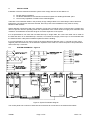
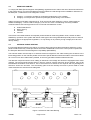
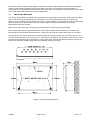


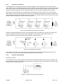


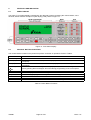
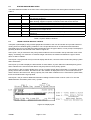
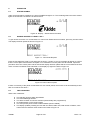
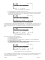
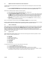


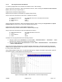

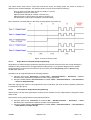

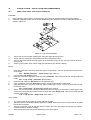

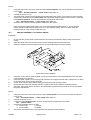
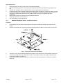
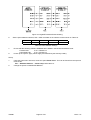
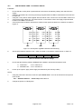

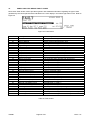
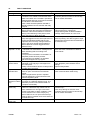


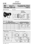
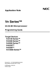


![[U4.PC.10] Macro commande MACR_ASPIC_MAIL](http://vs1.manualzilla.com/store/data/006377674_1-db7350395a2cd327647fed608ca6fb4f-150x150.png)