1
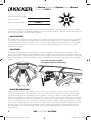
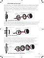
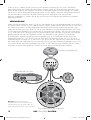
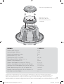
KM
KMCOMPONENTSYSTEM
KM6250.2
English Version
Versión Español
Altavoz Componente KM
Manual del Propietario
Deutsche Version
KM Komponenten-System
Benutzerhandbuch
Version Française
Kits deux voies KM
Manuel d’utilisation
2009 KM Components Multilingual c01.indd 1
11/21/2008 3:37:53 PM
KMMarineComponentSystemOwner’sManual
Model: KM6250.2
Authorized KICKER Dealer:
Purchase Date:
Speaker Model Number:
KM6250.2
Your KM component system speakers were specially designed for “Livin’ Loud” out in the harsh marine
environment. They are magnetically shielded and use advanced materials and construction techniques to
maintain optimal performance for years to come.
APPLICATION
The Kicker KM component system speakers are specifically designed for mounting in free-air applications.
The speakers do not require a sealed enclosure for optimum performance. It is important to isolate the
sound coming off the front of the driver from the sound radiating from the back of the driver. This isolation
is usually accomplished by using the driver in a factory speaker location, or in a location with a semiisolated rear chamber.
LOCATION
The sound produced by the KM component system is directional, particularly for the tweeter’s sonic
output. Find the best location for stereophonic sound. If necessary, add more KM component systems or
KM coaxial speakers (Kicker KM6200) to the system to help distribute and balance the sound-stage. After
determining the best mounting locations, carefully check the areas where the mounting hardware will be
placed.
Possible locations for KM
Component Speaker Mounting
WOOFER MOUNTING
Make sure the stainless steel mounting screws and U-type speed clips will not puncture the fuel cell,
wiring, or interfere with any mechanical parts on the underside of the mounting surface. Use the woofer
“template” inside your KM component system speaker’s shipping carton to mark the woofer mounting
hole, then cut directly on the line. Pre-drill the mounting screw holes using a 7/64” (2.5mm) bit, and attach
the KM component system woofer to the boat, by fastening the supplied stainless steel course-threaded
screws to the boat’s structure. If applicable, utilize the enclosed stainless steel U-type speed clips. Mount
the speaker and grille right side-up to take advantage of the KM component woofer’s integrated moisture
draining system. The Grilles are removable for custom painting applications. If the supplied hardware is
not applicable to your installation, some other means of securely attaching the speakers to the vessel
must be used.
2
2009 KM Components Multilingual c01.indd 2
KMCOMPONENTSYSTEM
11/21/2008 3:38:05 PM
TWEETER MOUNTING
The tweeter can be mounted one of three ways: flush, surface and angled mounting. For flush
mounting applications, choose a flat location on the panel with space behind the panel to allow room for
the mounting nut. After checking the clearances, cut the appropriate mounting hole diameter in the panel
(see the chart below). Place the shorter mounting nut behind the panel. Feed the wire through the hole in
the panel and the mounting nut. Mount the tweeter by screwing the mounting nut onto the tweeter.
panel
tweeter
short
mounting nut
flush ring
Flush Mounting the Tweeter
For surface mounting applications use the surface mount cup as a template and pre-drill two 7/64”
(2.5mm) screw holes for attaching the mounting cup to the panel, and a 5/16” (8mm) hole for the wires.
Two #8 flathead stainless steel sheet metal screws are supplied to attach the mounting cup to the panel.
Position the tweeter over the mounting cup and press it into position.
panel
tweeter
surface mount
cup
Surface Mounting the Tweeter
For angled mounting applications choose a flat location on the panel with space behind the panel to
allow room for the mounting nut and back angle ring. After checking the clearances, cut the appropriate
mounting hole diameter in the panel (see the chart below). Place the front angle ring (does not fit through
the longer tweeter mounting nut) in front of the panel. Then place the wire and tweeter through the front
angle ring and into the panel. Next place the wire through the back angle ring (fits through the longer
tweeter mounting nut), place the back angle ring over the rear of the tweeter, and line-up the narrow
part of the front angle ring for the preferred angle of operation. Place the wire through the longer tweeter
mounting nut and loosely tighten the mounting nut around the tweeter. Rotate all the parts in unison until
the tweeter is angled in the desired direction. Secure the assembly by tightening the tweeter mounting
nut.
panel
long
mounting nut
back angle ring
front angle ring
Angle Mounting the Tweeter
3
2009 KM Components Multilingual c01.indd 3
11/21/2008 3:38:09 PM
WIRING
Carefully place the speaker wire in a location that is clear of standing water and moving components of
the vessel. For reference, the Blue wire is Positive and the Grey wire is Negative. Mount the crossover to
the woofer’s back plate with the enclosed phillips-head M3 stainless steel machined screws, or mount
the crossover remotely in a location free and clear of standing water. The locking crossover cover with
water resistant gasket is removable for wiring installation; it helps prevent terminal corrosion and electrical
shorting. The positive and negative gold plated terminals are of different sizes and correspond to the
appropriate gold plated positive and negative wire connectors. Take off the crossover cover, and connect
the wire from the woofer to the “WF” terminal and the wire from the tweeter to the “TW” terminal. Connect
the supplied 15 feet (4.5m) of wire to “IN” terminal in the crossover. Carefully route the wires through the
slot between the crossover and crossover cover, and snap the crossover cover back on the crossover.
Connect the other end of the heavy gauge wire to your amplifier in accordance with its owner’s manual.
Crossover Cover
Slot
Source Unit or Amplifier
SPKR + SPKR -
Integrated moisture draining system
4
2009 KM Components Multilingual c01.indd 4
KMCOMPONENTSYSTEM
11/21/2008 3:38:11 PM
Crossover Cover
Crossover mounted
to the KM Component
Woofer’s Back Plate
MODEL:
KM6250.2
Woofer Size, in (cm)
6 (16)
Tweeter Size, in (mm)
1 (25)
Dome Material
Titanium
Nominal Impedence [Zn], ohm
4
Power Handling* Watts, Peak (RMS)
225 (75)
Sensitivity [SPL0], db @ 1W, !m
88
Effective Frequency Range, Hz
35-21k
Woofer Mounting Hole Diameter, in (cm)
5 1/8 (13)
Woofer Mounting Depth w/o Crossover, in (cm)
2 7/8 (7.2)
Flush Mounting Tweeter Hole Diameter, in (cm)
1 13/16 (4.5)
High Pass, dB, at Frequency, Hz
18, 4000
Low Pass, dB, at Frequency, Hz
12, 4000
Bolt-Thru Grilles
Yes
Kicker Marine speakers use the highest level of magnetic shielding available to minimize compass and gauge deviation
in your dash. Kicker Marine speakers meet or exceed industry standards for environmental humidity and corrosion,
and for material degradation due to UV exposure.
2009 KM Components Multilingual c01.indd 5
5
11/21/2008 3:38:13 PM
KMSistemaComponenteManualdelPropietario
Modelo: KM6250.2
Distribuidor autorizado de Kicker:
Fecha de compra:
Número de modelo de altavoz:
Su KM sistemas de componentes se diseñó para “Livin’ Loud” en el ambiente marino duro. Se
protege magnéticamente y utiliza las técnicas avanzadas de materias y construcción para mantener el
desempeño que óptimo para años para venir.
APLICACIÓN
Sus sistemas de componentes de la serie KM de KICKER han sido diseñados específicamente para
montarlos en aplicaciones al aire libre. A pesar de que los altavoces no necesitan una caja sellada para
un rendimiento óptimo, es importante separar el sonido radiado por delante del sonido radiado por detrás
del altavoz. Esta separación se logra normalmente usando un excitador de tamaño correcto en un lugar
preestablecido de fábrica para el altavoz.
POSISITON
El sonido producido por los altavoces Componente del KM es direccional, especialmente para la
producción sónica de altavoz. Encuentre el mejor posisition para el sonido estereofónico. Si necesario,
agrega más altavoces Componente o Coax (Kicker KM6200) del KM al sistema para ayudar a distribuir y
equilibrar la sano-etapa. Después que determinar el mejor posistions que monta, verifica con cuidado las
áreas donde el hardware que monta irá.
Posistions posible para los altavoces
Componente del KM que Montan
MONTAJE
El acero inoxidable encerrado que monta los tornillos y clipes DE TIPO U de velocidad no deben romper
la célula del combustible, alambrar, ni intervenir con ninguna parte mecánica en la cara inferior de la
superficie que monta. Utilice el “plantilla” dentro de su altavoz Componente del KM es el cartón del envío
de marcar el hoyo que monta, entonces corte directamente en la línea. El pre-taladro los hoyos del tornillo
que montan que utiliza un 7/64” (2.5mm) el taladro, y conecta los altavoces Componente del KM al
barco, abrocha el acero inoxidable suministrado los tornillos curso-enhebrados a la estructura del barco.
Si aplicable, utiliza el acero inoxidable encerrado clipes DE TIPO U de velocidad. Monte el altavoz y
la rejilla para aprovecharse de boca arriba el sistema del altavoz ha integrado sistema de desaguar
de humedad. Las Rejillas son movibles para aplicaciones de pintar de costumbre. Si el hardware
suministrado no es aplicable a su instalación, algunos otros medios de conectar seguramente a los
oradores a la nave se debe utilizar.
6
2009 KM Components Multilingual c01.indd 6
KMCOMPONENTSYSTEM
11/21/2008 3:38:13 PM
TWEETER MONTAJE
El altavoz se puede montar uno de tres maneras: limpía, la superficie y montar angulado. Para
aplicaciones de montar de limpíe, se refiere por favor a la ilustración. Escoja una ubicación plana en
el panel con el espacio detrás del panel para permitir el espacio para la tuerca que monta. Después que
verificar los espacios libres, cortan el diámetro apropiado de hoyo que monta en el panel (ve el pie de
página). Coloque la tuerca más corta que monta detrás del panel. Alimente el cable del tweeter por el
hoyo en el panel y la tuerca que montan. Monte el tweeter enroscando la tuerca que monta en el tweeter.
Panel
Tuerca más
corta que monta
Reborde
de tweeter
Tweeter
Montar Limpíe
Para aplicaciones de montar de superficie utiliza la copa de superficie del monte como una plantilla y
pre-taladro dos 7/64” (2.5mm) hoyos de tornillo para conectar la copa de superficie del monte al panel,
y un 5/16” (8mm) hoyo para los cables del altavoz. Dos #8 tornillos inoxidables se suministran para
conectar la copa de superficie del monte al panel. Posicione el tweeter sobre la copa de superficie del
monte y lo aprieta en posición.
Panel
Tweeter
Copa de superficie
del monte
Superficie Montar
Para montar angulado las aplicaciones escogen una ubicación plana en el panel con el espacio detrás
del panel para permitir el espacio para la tuerca que monta y el anillo del ángulo de espalda. Después
que verificar los espacios libres, cortan el diámetro apropiado de hoyo que monta en el panel (ve el pie
de página). Coloque el anillo anterior del ángulo (no queda por el tweeter más largo que monta tuerca)
delante del panel. Coloque el cable del altavoz y el tweeter por el anillo anterior del ángulo y en el panel.
Coloque el cable del altavoz por el anillo del ángulo de espalda (los ataques por el tweeter más largo
que monta tuerca), coloca el anillo del ángulo de espalda sobre el trasero del tweeter, y de la alineación
la parte estrecha del anillo anterior del ángulo para el ángulo preferido de la operación. Coloque el cable
del altavoz por el tweeter más largo que monta tuerca y aprieta flojamente la tuerca que monta alrededor
del tweeter. Gire todas las partes al unísono hasta que el tweeter esté angulado en la dirección deseada.
Asegure la asamblea apretando el tweeter que monta tuerca.
Panel
Tweeter
Tuerca más larga
que monta
Anillo del ángulo de espalda
Montar Angulado
2009 KM Components Multilingual c01.indd 7
Anillo anterior
del ángulo
7
11/21/2008 3:38:18 PM
CABLEADO
Coloque el cable del altavoz en un posistion vacía de agua parada y componentes móviles del barco.
Para la referencia, el cable azul es Positivo y el cable de gris es Negativo. Monte el crossover al plato de
la espalda del altavoz para sonidos graves con la phillips-M3 encerrada inoxidable los tornillos, o monta
el crossover remotamente en una posistion vacía de agua parada. El cerrar la cubierta terminal con agua
junta de culata resistente es movible para la instalación de cable. La junta de culata previene la corrosión
terminal y shorting eléctrico. Las terminales positivas y negativas de oro son de tamaño y corresponder
diferentes a los conectores apropiados, positivos y negativos del cable del altavoz. Tome de la cubierta
de crossover, y conecte el cable del altavoz del altavoz para sonidos graves al “WF” terminal y el cable
de altavoz del tweeter al “TW” terminal. Conecte el suministró 15 pies (4.5m) de cable de altavoz al
“EN” terminal en el crossover. Dirija con cuidado el cable del altavoz por la ranura entre el crossover y la
cubierta de crossover, y chasquée la espalda de la cubierta de crossover en el crossover. Conecte el
otro fin del cable del altavoz a su amplificador de acuerdo con su manual.
Cubierta de
Crossover
Ranura
Unidad fuente o amplificador
SPKR + SPKR -
Garantía Comuníquese con su concesionario o
distribuidor Kicker internacional para obtener infor
ación sobre procedimientos específicos relacionados
con las normas de garantía de su país.
8
2009 KM Components Multilingual c01.indd 8
Integrado sistema de
desaguar de humedad
KMCOMPONENTSYSTEM
11/21/2008 3:38:20 PM
Cubierta de
Crossover
El crossover montó
al plato de la espalda
del Altavoz para
sonidos graves del
componente del KM
MODELO:
KM6250.2
Tamaño del woofer, plg (cm)
6 (16)
Tamaño del tweeter, plg (cm)
1 (25)
Material del diafragma del tweeter
Titanio
Impedancia nominal [Zn], ohmio
4
Procesamiento máximo de potencia, vatios (RMS)
225 (75)
Sensibilidad [SPLo], dB @ 1W, 1m
88
Gama de potencias, Hz
35-21k
Diámetro del agujero de montaje, plg (cm)
5 1/8 (13)
Profundidad de montaje superior sin crossover, plg (cm)
2 7/8 (7.2)
Limpíe Montar el Diámetro del agujero de tweeter, plg (cm)
1 13/16 (4.5)
Paso alto, dB por octava, en la Frecuencia, Hz
18, 4000
Paso bajo, dB por octava, en la Frecuencia, Hz
12, 4000
Cierre por rejillas
Si
Los altavoces Kicker marinos tienen proteger magnético y aminoran la desviación de brújula y calibrador. Los
altavoces Kicker marinos encuentran o exceden los estándares de la industria para la humedad y la corrosión
ambientales, y para la degradación material debido a la exposición de ultravioleta.
2009 KM Components Multilingual c01.indd 9
9
11/21/2008 3:38:21 PM
KMKomponenten-SystemeBenutzerHandBuch
Modelle: KM6250.2
Authorisierter KICKER Händler:
Einkaufsdatum:
Lautsprecher Modell Nummer:
Ihr KM Komponenten-System wurde besonders für “Livin’ Loud” in der harten Marineumwelt entworfen.
Es ist magnetisch beschützt. Es ist Materialien und Konstruktion fortgeschritten beizubehalten, dass ideale
Leistung jahrelang kommt.
EINBAU
Das Kicker Komponenten-System der KM-Serie ist speziell für den Einbau in nicht geschlossenen
Gehäusen gedacht. Die Lautsprecher benötigen für optimale Leistung kein geschlossenes Gehäuse.
Es ist wichtig, den vorne aus dem Lautsprecher austretenden Schall vom Schall zu trennen, der von der
Rückseite des Lautsprechers kommt. Diese Trennung wird meist durch die Verwendung der korrekten
Treibergröße und Einbau an einer isolierten hinteren Stelle erreicht. .
POSITION
Die Position und Ausrichtung Ihres KM Komponenten-Systems beeinflusst die Qualität und Quantität
der Wiedergabe, besonders für die Schallausgabe des Hochtonlautsprechers. Finden Sie den besten
Ort für stereofonischen Klang. Installieren von mehr Lautsprechern (siehe auch das Kicker KM6200
Koax-System) zum Boot verteilt und gleicht die Räumlichkeit aus. Nachdem Sie die beste Einbauposition
gewählt haben, prüfen Sie sorgfältig die Stellen, an denen Montagehalterungen angebracht werden
sollen.
Orte für KM KomponentenSysteme installation
INSTALLATION
Vergewissern Sie sich, dass die Montageschrauben keine Benzintanks, Kabel usw. anbohren oder
Mechanismen an der Unterseite der Einbauoberfläche stören würden. Die Pappschablone im Lieferkarton
des KM Komponenten-Systems kann als Vorlage für das Ausschneiden des Lautsprechermontagelochs
aus Ihrem Gehäuse verwendet werden. Nachdem Sie Ihre Schallwand mit der Schablone markiert haben,
müssen Sie direkt an der Linie ausschneiden. Bohren Sie die Löcher mit einem 2,5-mm-Bohrer vor, und
befestigen Sie das KM Komponenten-System an das Boot mit den beiliegenden Edelstähle-Schrauben
in die Struktur des Boots. Wenn zutreffend, verwenden Sie wenn die eingeschlossene Edelstahl “U-Type
Speed” Klammern. Installieren Sie das KM Komponenten-System und den Schutzgitter ordentlich, mit
dem Feuchtigkeit entwässernd Steckplatz am Boden. Wenn die beiliegenden Befestigungselemente
nicht für Ihre Installation passen, muss eine andere Methode zur sicheren Befestigung des Systems am
Fahrzeug verwendet werden.
10
2009 KM Components Multilingual c01.indd 10
KMCOMPONENTSYSTEM
11/21/2008 3:38:22 PM
HOCHTÖNER INSTALLATION
Der Hochtöner kann Ein von drei Wegen aufgestellt werden: flach mit der Oberfläche, an der Oberfläche
und mit Winkelringen an der Oberfläche montiert werden. Für flach mit der Oberfläche montiert werden.
Finden Sie einen flachen Ort auf dem Unterausschuss mit Platz hinter dem Unterausschuss für die
Befestigungsmutter. Schneiden Sie den passenden Hochtöner Flach-Montageloch-Durchmesser im
Unterausschuss (siehe das Leistungsdiagramm unten). Stellen Sie die kürzere Befestigungsmutter
hinter den Unterausschuss. Führen Sie den Draht durch das Loch im Unterausschuss und der
Befestigungsmutter zu. Stellen Sie den Hochtöner durch Schrauben der Befestigungsmutter auf den
Hochtöner auf.
Unterausschuss
Hochtöner
Hochtöner-Flansch
Kürzere
Befestigungsmutter
Flach Mit Der Oberfläche
Für Oberflächen Befestigungsanwendungen benutzt die Oberflächen-Untersatztasse als ein Modellrahmen
und vordrill zwei 2,5 mm Schraubenlöcher für die Oberflächen-Untersatztasse zum Unterausschuss, und
einem 8 mm Loch für die Drähte. Schrauben Sie die Oberflächen-Untersatztasse zum Unterausschuss
mit den zwei eingeschlossen #8 Edelstahl Flachkopfschrauben. Stellen Sie den Hochtöner über der
Oberflächen-Untersatztasse ein und drücken Sie ihn in Position.
Unterausschuss
OberflächenUntersatztasse
Hochtöner
An Der Oberfläche
Für mit Winkelringen an der Oberfläche montiert werden, siehe Abbildung. Finden Sie einen flachen
Ort auf dem Unterausschuss mit Platz hinter dem Unterausschuss für die Befestigungsmutter
und hinteren Winkelring. Schneiden Sie den passenden Hochtöner Flach-MontagelochDurchmesser im Unterausschuss (siehe das Leistungsdiagramm unten). Stellen Sie den vorderen
Winkelring (er passt durch die längere Befestigungsmutter nicht) vor dem Unterausschuss.
Stellen Sie dann den Draht und den Hochtöner durch den vorderen Winkelring und in den
Unterausschuss
Hochtöner
längere
Befestigungsmutter
Hinterer Winkelring
Mit Winkelringe An Der Oberfläche
2009 KM Components Multilingual c01.indd 11
vorderer Winkelring
11
11/21/2008 3:38:26 PM
Unterausschuss. Stellen Sie den Draht durch den hinteren Winkelring (er passt durch die längere
Befestigungsmutter) auf. Stellen Sie den hinteren Winkelring über die Hinterseite vom Hochtöner, und
leinen Sie der enge Teil vom vorderen Winkelring für den bevorzugten Winkel des Betriebs auf. Stellen
Sie den Draht durch die längere Befestigungsmutter auf, und “locker” festziehen die Befestigungsmutter
um den Hochtöner. Drehen Sie alle Teile in Einklang, bis der Hochtöner in der gewünschten
Richtung umgebogen ist. Sichern Sie die Versammlung durch Festziehen den Hochtöner aufstellend
Befestigungsmutter.
VERKABELUNG
Stellen Sie die Verkabelung in einen Ort, der klar von Stehenwasser und Bewegenbauteilen vom Gefäß ist.
Das blaue Kabel ist positiv und das silberne Kabel ist negativ. Stellen Sie die Überkreuzung zur Rückwand
des Tieftonlautsprechers mit dem eingeschlossenen Kreuzschlitzkopf M3-Edelstahl Schrauben, oder
stellen Sie die Überkreuzung in einen Ort, der klar von Stehenwasser und Bewegenbauteilen vom Gefäß
ist. Die Überkreuzungbedeckung ist abnehmbar für Verkabelungsinstallation, und wenn verschlossenenin-Ort, unterstützt sie in Zündungsschutz und die Verhinderung von Korrosion. Die positive und negative
goldene Stecker sind von verschiedenen Größen und verbinden zu den positiven und negativen
Drahtverbindern. Nehmen Sie die Überkreuzungsbedeckung ab und verbinden Sie den Draht vom
Tieftonlautsprecher zum “WF” Terminal und der Draht vom Hochtonlautsprecher zum “TW” Terminal.
Verbinden Sie das versorgte 4,5 m von Draht zu “IN” Terminal in der Überkreuzung. Leiten Sie vorsichtig
die Drähte durch den Steckplatz zwischen der Überkreuzung und der Überkreuzungsbedeckung um und
schnappen Sie die Überkreuzungsbedeckung zurück auf der Überkreuzung. Verbinden Sie das andere
Ende vom schweren Messgerätdraht zu Ihrem Verstärker gemäß seinem Benutzerhandbuch.
Überkreuzungsbedeckung
Steckplatz
Autoradio oder Verstärker
SPKR + SPKR -
Garantie Nehmen Sie mit Ihren
internationalen Kicker-Fachhändler oder
Vertrieb Kontakt auf, um Details über die
Garantieleistungen in Ihrem Land zu erfahren.
Feuchtigkeit entwässernd Steckplatz
12
2009 KM Components Multilingual c01.indd 12
KMCOMPONENTSYSTEM
11/21/2008 3:38:28 PM
Überkreuzungsbedeckung
Überkreuzung zur
Rückwand des KM
Komponenten-Systems
aufgestellt
MODEL:
KM6250.2
Tieftönergröße, Zoll (cm)
6 (16)
Hochtönergröße, Zoll (mm)
1 (25)
Material der Hochtönermembran
Titan
Nennimpedanz [Zn], Ohm
4
Spitzenbelastbarkeit, Watt (RMS)
225 (75)
Empfindlichkeit [SPLo], dB bei 1 W, 1 m
88
Effektiver Frequenzbereich, Hz
35-21k
Tieftöner Montageloch-Durchmesser, Zoll (cm)
5 1/8 (13)
Tieftöner Montagetiefe ohne Überkreuzung, Zoll (cm)
2 7/8 (7,2)
Hochtöner Flach-Montageloch-Durchmesser, Zoll (cm)
1 13/16 (4,5)
Hoher Überkreuzungspunkt, dB, an Frequenz, Hz
18, 4000
Niedriger Überkreuzungspunkt, dB, an Frequenz, Hz
12, 4000
Schraube-durch Schutzgitter
Ja
Änderungen an Spezifikationen und Leistungswerten vorbehalten. Sie finden die aktuellsten Informationen
bei kicker.com. Anmerkung: Um die besten Ergebnisse zu erzielen, benutzen Sie nur Originalzubehörteile und
Kabel von KICKER.KM Marine-Lautsprecher benutzen magnetische Beschützung und minimieren Kompass
und Messgerätabweichung in Ihrem Marinefahrzeug. KM Marine-Lautsprecher treffen sich oder überschreiten
13
Industrienstandards für Umweltfeuchtigkeit und Korrosion, und für materiellen Abbau auf Grund Ultraviolett Aussetzung.
2009 KM Components Multilingual c01.indd 13
11/21/2008 3:38:30 PM
Manueld’utilisationdeskitsdeuxvoiesKM
Modèles : KM6250.2
Distributeur Kicker agréé :
Date d’achat :
Numéro de modèle du haut-parleur :
Votre KM kits deux voies a été conçu pour l’environnement marin dur. L’haut-parleur est
magnétiquement protégé et utilise des matériels avancés et les techniques de construction pour maintenir
l’exécution optimale pendant des années pour venir.
APPLICATION
Ces haut-parleurs kits deux voies Kicker KM ont été spécialement conçus pour un montage sans
enceinte. Leur fonctionnement optimal ne nécessite pas d’enceinte close, mais il est important d’isoler
le son sortant par l’avant du haut-parleur et le son diffusé à l’arrière du haut-parleur. En général, cette
isolation est obtenue en installant dans un emplacement standard un haut-parleur de taille adéquate, ou
dans un emplacement avec un demi-isolé la chambre postérieure.
EMPLACEMENT
Le son produit par l’haut-parleur kits deux voies de KM est directionnel, particulièrement pour la
production sonore du tweeter. Trouver le meilleur emplacement pour le son stéréophonique. Si
nécessaire, ajouter les haut-parleurs kits deux voies ou coaxiaux (Kicker KM6200) de KM au système
pour aider distribuent et équilibrent la son-étape. Après avoir déterminé les emplacements le mieux
montants, soigneusement vérifier les secteurs où le matériel montant sera placé.
Emplacements possibles pour
monter kits deux voies KM
MONTER
Assurer que l’acier inoxydable enclos montant des vis et les trombones de vitesse de type d’ « U » ne
crèveront pas la cellule de carburant, l’installation éléctrique, ou interférer avec les parties mécaniques sur
le dessous de la surface montant. Utiliser le “le gabarit” dans la boîte de l’expédition de votre haut-parleur
pour marquer le trou montant, l’alors coupure directement sur la ligne. Pré-entraîner les trous montant
de vis utilisant un 7/64” (2,5mm) le morceau, et attacher les haut-parleurs au bateau, en attachant les
vis d’acier inoxydable fournies à la structure du bateau. Le cas échéant, utiliser les trombones enclos
de vitesse de type d’ « U » d’acier inoxydable. Monter l’haut-parleur et la grille à l’endroit pour profiter de
l’haut-parleur s’humidité intégrée draine le système. Les grilles sont détachables pour les applications de
tableau de coutume. Si le matériel fourni n’est pas applicable à votre installation, quelques autres moyens
d’attachant assurément les haut-parleurs au bateau doivent être utilisés.
14
2009 KM Components Multilingual c01.indd 14
KMCOMPONENTSYSTEM
11/21/2008 3:38:30 PM
TWEETER MONTER
Le tweeter peut être monté un de trois façons : plat, la surface et monter incliné. Pour monter plates
les applications, s’il vous plaît se référer à l’illustration. Choisir un emplacement plat sur le panneau
avec l’espace derrière le panneau pour permettre la pièce pour le écrou montant. Après avoir vérifié les
dégagements, couper le diamètre de trou montant approprié dans le panneau (voir ci-dessous). Placer le
écrou montant plus courte derrière le panneau. Nourrir le câble d’haut-parleur par le trou dans le panneau
et le écrou montant. Monter le tweeter en vissant le écrou montant sur le tweeter.
Pannea
Enjoliveur de hautHaut-parleur
parleur d’aigus
d’aigus
Le écrou montant
plus courte
Montage Plat
Pour surface monter les applications utilise la tasse de mont de surface comme un gabarit et entraîne
pré-deux 7/64” (2,5mm) les trous de vis pour attacher la surface montant la tasse au panneau, et un
5/16” (8 mm) le trou pour le câble d’haut-parleur. Deux #8 vis à tête plate d’acier inoxydable sont fournies
pour attacher la surface montant la tasse au panneau. Disposer le tweeter par-dessus la surface montant
la tasse et l’appuie en place.
Pannea
Haut-parleur
La tasse de
d’aigus
mont de surface
Surface Monter
Pour incliné montant des applications choisissent un emplacement plat sur le panneau avec l’espace
derrière le panneau pour permettre la pièce pour le écrou montant et l’anneau arrière d’angle. Après avoir
vérifié les dégagements, couper le diamètre de trou montant approprié dans le panneau (voir ci-dessous).
Placer l’anneau d’angle de devant (pas capable par le écrou montant plus longue) devant le panneau.
Placer le câble d’haut-parleur et le tweeter par l’anneau d’angle de devant et dans le panneau. L’endroit
prochain le câble d’haut-parleur par l’anneau d’angle arrière (les crises par la noix montant plus longue),
placer l’anneau d’angle arrière par-dessus l’arrière du tweeter, et la file la partie étroite de l’anneau d’angle
de devant pour l’angle préféré d’opération. Placer le câble d’haut-parleur par le écrou montant plus longue
et resserrer lâchement le écrou montant autour du tweeter. Tourner toutes les parties dans l’unisson
jusqu’à ce que le tweeter est incliné dans la direction désirée. Obtenir l’assemblée en resserrant le écrou
montant plus longue.
Pannea
Haut-parleur
d’aigus
Le écrou montant
plus longue
L’anneau arrière d’angle
Monter Incliné
2009 KM Components Multilingual c01.indd 15
L’anneau d’angle
de devant
15
11/21/2008 3:38:35 PM
CÂBLAGE
Placer le câble dans un emplacement éclaircit d’eau permanente et de composants en mouvement du
vaisseau. Pour la référence, le câble d’haut-parleur bleu est positif et le câble d’haut-parleur argent est
négatif. Monter le croisé à la plaque arrière de woofer avec l’enclos M3 vis d’acier inoxydable, ou monter
le croisé vaguement dans un emplacement libère d’eau permanente. Le verrouiller la couverture croisée
avec l’eau joint résistant est détachable pour l’installation de câble d’haut-parleur ; il aide empêche
la corrosion délimitante et shorting électrique. Les terminaux positifs et négatifs en or sont de tailles
différentes et correspondent aux connecteurs de câble d’haut-parleur appropriés, en or, positifs et
négatifs. Partir la couverture croisée, et connecter le câble d’haut-parleur du woofer au “WF” le terminal
et le fil du tweeter au “TW” le terminal. Connecter l’a fourni 15 pieds (4,5m) de fil à “IN” le terminal dans le
croisé. Soigneusement la route le câble d’haut-parleur par l’entaille entre la couverture croisée et croisée,
et claquer la couverture croisée de retour sur le croisé. Connecter l’autre fin du câble d’haut-parleur à
votre amplificateur conformément à son manuel du propriétaire.
Couverture croisée
Entaille
Appareil source ou amplificateur
SPKR + SPKR -
Garantie Pour connaître les procédures
propres à la politique de garantie de
votre pays, contactez votre revendeur ou
distributeur International Kicker.
16
2009 KM Components Multilingual c01.indd 16
L’humidité intégrée draine le système
KMCOMPONENTSYSTEM
11/21/2008 3:38:37 PM
Couverture croisée
Croisé monté à
la plaque arrière
de woofer
MODEL:
KM6250.2
Diamètre du haut-parleur de graves, in (cm)
6 (16)
Diamètre du haut-parleur d’aigus, in (mm)
1 (25)
Matériau de la membrane de haut-parleur d’aigus
Titane
Impédance nominale [Zn], ohms
4
Puissance admissible, watts, crête (efficace)
225 (75)
Sensibilité [SPLo], dB @ 1 W, 1 m
88
Plage de fréquence effective, Hz
35-21k
Dimensions découpe de woofer, in (cm)
5 1/8 (13)
Profondeur de montage sans croisé, in (cm)
2 7/8 (7,2)
Dimensions découpe de Tweeter Montant plat, in (cm)
1 13/16 (4,5)
L’haute passe, dB, à la Fréquence, Hz
18, 4000
La passe basse, dB, à la Fréquence, Hz
12, 4000
Visser aux grilles
Oui
Les Kicker KM haut-parleurs utilisent le plus haut niveau de protéger magnétique disponible pour minimiser la déviation
de compas et jauge. Les Kicker KM haut-parleurs rencontrent ou dépassent les normes d’industrie pour l’humidité et
17
la corrosion écologique, et pour la dégradation matérielle en raison de l’exposition ULTRAVIOLETE.
2009 KM Components Multilingual c01.indd 17
11/21/2008 3:38:38 PM
ElectronicsLimitedWarranty
Kicker warrants this product to be free from defects in material and workmanship under normal use for a period of
THREE (3) MONTHS from date of original purchase with receipt. When purchased from an Authorized KICKER Dealer it is
warranted for TWO (2) YEARS from date of original purchase with receipt. In all cases you must have the original receipt.
Should service be necessary under this warranty for any reason due to manufacturing defect or malfunction during the
warranty period, Kicker will repair or replace (at its discretion) the defective merchandise with equivalent merchandise at
no charge. Warranty replacements may have cosmetic scratches and blemishes. Discontinued products may be replaced
with more current equivalent products.
This warranty is valid only for the original purchaser and is not extended to owners of the product subsequent to
the original purchaser. Any applicable implied warranties are limited in duration to a period of the express warranty
as provided herein beginning with the date of the original purchase at retail, and no warranties, whether express or
implied, shall apply to this product thereafter. Some states do not allow limitations on implied warranties; therefore these
exclusions may not apply to you. This warranty gives you specific legal rights; however you may have other rights that
vary from state to state.
WHAT TO DO IF YOU NEED WARRANTY OR SERVICE
Defective merchandise should be returned to your local Authorized Stillwater Designs (Kicker) Dealer for warranty
service. Assistance in locating an Authorized Dealer can be found at www.kicker.com or by contacting Stillwater
Designs directly. You can confirm that a dealer is authorized by asking to see a current authorized dealer window decal.
If it becomes necessary for you to return defective merchandise directly to Stillwater Designs (Kicker), call the Kicker
Customer Service Department at (405) 624-8510 for a Return Merchandise Authorization (RMA) number. Package all
defective items in the original container or in a package that will prevent shipping damage, and return to:
Stillwater Designs, 3100 North Husband, Stillwater, OK 74075
The RMA number must be clearly marked on the outside of the package. Please return-only defective components. The
return of functioning items increases your return freight charges. Non-defective items will be returned freight-collect to
you.
Include a copy of the original receipt with the purchase date clearly visible, and a “proof-of-purchase” statement listing
the Customer’s name, Dealer’s name and invoice number, and product purchased. Warranty expiration on items without
proof-of-purchase will be determined from the type of sale and manufacturing date code. Freight must be prepaid; items
sent freight-collect, or COD, will be refused.
WHAT IS NOT COVERED?
This warranty is valid only if the product is used for the purpose for which it was designed.
It does not cover:
o Damage due to improper installation
o Subsequent damage to other components
o Damage caused by exposure to moisture, excessive heat, chemical cleaners, and/or UV radiation
o Damage through negligence, misuse, accident or abuse. Repeated returns for the same damage may be considered
abuse
o Any cost or expense related to the removal or reinstallation of product
o Speakers damaged due to amplifier clipping or distortion
o Items previously repaired or modified by any unauthorized repair facility
o Return shipping on non-defective items
o Products with tampered or missing barcode labels
o Products returned without a Return Merchandise Authorization (RMA) number
o Freight Damage
o The cost of shipping product to Kicker
o Service performed by anyone other than Kicker
HOW LONG WILL IT TAKE?
Kicker strives to maintain a goal of 72-hour service for all electronics (amplifiers, crossovers, equalizers, etc.) returns.
Delays may be incurred if lack of replacement inventory or parts is encountered.
Failure to follow these steps may void your warranty. Any questions can be directed to the Kicker Customer Service
Department at (405) 624-8510.
NOTE: All specifications and performance figures are subject to change. Please visit the www.kicker.com for the most current information.
18
2009 KM Components Multilingual c01.indd 18
KMCOMPONENTSYSTEM
11/21/2008 3:38:39 PM
InternationalWarranty
Contact your International Kicker dealer or distributor concerning specific procedures for your country’s warranty policies.
WARNING: KICKER products are capable of producing sound levels that can permanently damage your hearing! Turning
up a system to a level that has audible distortion is more damaging to your ears than listening to an undistorted system at
the same volume level. The threshold of pain is always an indicator that the sound level is too loud and may permanently
damage your hearing. Please use common sense when controlling volume.
GARANTÍA INTERNACIONAL
VersiónEspañol
Comuníquese con su concesionario o distribuidor Kicker internacional para obtener infor ación sobre procedimientos
específicos relacionados con las normas de garantía de su país.
ADVERTENCIA: Los excitadores Kicker son capaces de producir niveles de sonido que pueden dañar permanentemente
el oído. Subir el volumen del sistema hasta un nivel que produzca distorsión es más dañino para el oído que escuchar un
sistema sin distorsión al mismo volumen. El dolor es siempre una indicación de que el sonido es muy fuerte y que puede
dañar permanentemente el oído. Sea precavido cuando controle el volumen.
La frase “combustible para vivir la vida Livin’ Loud™ a todo volumen” se refiere al entusiasmo por la vida que la marca
Kicker de estéreos de automóvil representa y a la recomendación a nuestros clientes de que vivan lo mejor posible (“a
todo volumen”) en todo sentido. La línea de altavoces y amplificadores Kicker es la mejor del mercado de audio de
automóviles y por lo tanto representa el “combustible” para vivir a todo volumen en el área de “estéreos de automóvil” de
la vida de nuestros clientes. Recomendamos a todos nuestros clientes que obedezcan todas las reglas y reglamentos
locales sobre ruido en cuanto a los niveles legales y apropiados de audición fuera del vehículo.
INTERNATIONALE GARANTIE
DeutscheVersion
Nehmen Sie mit Ihren internationalen Kicker-Fachhändler oder Vertrieb Kontakt auf, um Details über die Garantieleistungen
in Ihrem Land zu erfahren.
WARNUNG: KICKER-Treiber können einen Schallpegel erzeugen, der zu permanenten Gehörschäden führen kann!
Wenn Sie ein System auf einen Pegel stellen, der hörbare Verzerrungen erzeugt, schadet das Ihren Ohren mehr, als ein
nicht verzerrtes System auf dem gleichen Lautstärkepegel. Die Schmerzschwelle ist immer eine Anzeige dafür, dass der
Schallpegel zu laut ist und zu permanenten Gehörschäden führen kann. Seien Sie bei der Lautstärkeeinstellung bitte
vernünftig!
Der Slogan “Treibstoff für Livin’ Loud” bezieht sich auf die mit den Kicker-Autostereosystemen assoziierte Lebensfreude
und die Tatsache, dass wir unsere Kunden ermutigen, in allen Aspekten ihres Lebens nach dem Besten (“Livin’ Loud”) zu
streben. Die Lautsprecher und Verstärker von Kicker sind auf dem Markt für Auto-Soundsysteme führend und stellen somit
den “Treibstoff” für das Autostereoerlebnis unserer Kunden dar. Wir empfehlen allen unseren Kunden, sich bezüglich der
zugelassenen und passenden Lautstärkepegel außerhalb des Autos an die örtlichen Lärmvorschriften zu halten.
GARANTIE INTERNATIONALE
VersionFrançaise
Pour connaître les procédures propres à la politique de garantie de votre pays, contactez votre revendeur ou distributeur
International Kicker.
AVERTISSEMENT: Les haut-parleurs Kicker ont la capacité de produire des niveaux sonores pouvant endommager
l’ouïe de façon irréversible ! L’augmentation du volume d’un système jusqu’à un niveau présentant une distorsion audible
endommage davantage l’ouïe que l’écoute d’un système sans distorsion au même volume. Le seuil de la douleur est
toujours le signe que le niveau sonore est trop élevé et risque d’endommager l’ouïe de façon irréversible. Réglez le volume
en faisant prevue de bon sens !
L’expression “ carburant pour vivre plein pot “ fait référence au dynamisme de la marque Kicker d’équipements audio
pour véhicules et a pour but d’encourager nos clients à faire le maximum (“ vivre plein pot “) dans tous les aspects de leur
vie. Les haut-parleurs et amplificateurs Kicker sont les meilleurs dans le domaine des équipements audio et représentent
donc pour nos client le “ carburant pour vivre plein pot “ dans l’aspect “ installation audio de véhicule “ de leur vie.
Nous encourageons tous nos clients à respecter toutes les lois et réglementations locales relatives aux niveaux sonores
acceptables à l’extérieur des véhicules.
MEMBER OF
National Marine
Manufacturers Association
P.O. Box 459 • Stillwater, Oklahoma 74076 • U.S.A. • (405) 624-8510
2009 KM Components Multilingual c01.indd 19
19
11212008-C+09KM
11/21/2008 3:38:39 PM
©2008 Stillwater Designs
2009 KM Components Multilingual c01.indd 20
11/21/2008 3:38:40 PM