1
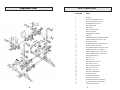
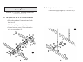
Power Tower
OWNER’S MANUAL
1-888-340-0482
Monday-Friday
8:30-5:30 Central Time
QUESTIONS?
Call Our Toll Free
Keys Fitness Helpline
1-888-340-0482
Keys Fitness Products, L.P.
4009 Distribution Dr.
Suite 250
Garland, Texas 75041
Keys Fitness Products, L.P.
P.O. Box 551239
Dallas, Texas 75355-1239
CAUTION!
Please read the precautions and
instructions in this manual before
using this equipment. Please save
this manual for future reference.
Keys Fitness is committed
to quality products that
demonstrate our commitment
to excellence!
Strength Trainer Series
Model: Power Tower
Questions?
Please call if:
• you need assistance about
operating your exercise unit
• parts are missing
• parts become worn or need to
be replaced
1-888-340-0482
Monday-Friday
8:30-5:30 Central Time
When requesting information please
have the following available:
• The Name
• The Model
• The Part Number
• The Description
KEYS FITNESS PRODUCTS, LP LIMITED WARRANTY
PRODUCT:
HOME USE WARRANTY:
STRENGTH TRAINER POWER TOWER
Frame: 1 YEAR
Parts: 90 DAYS
This Limited Warranty applies in the United States and Canada to products manufactured or distributed by Keys
Fitness Products, LP (“Keys”) under the KEYS brand name. The warranty period to the original purchaser is listed above
in the table.
Keys warrants that the Product you have purchased for use from Keys or from an authorized Keys reseller is free
from defects in materials or workmanship under normal use during the warranty period. Your sales receipt, showing the
date of purchase of the Product, is your proof of purchase. This warranty only extends to you, the original purchaser. It is
not transferable to anyone who subsequently purchases the Product from you. It excludes expendable parts (wear items).
Wear items pertain to components that might need to be replaced due to normal wear and tear. These items vary per
product but will include computer overlays, pedal straps, rope cords, seats, grips, chains, bottom bracket assemblies,
pads, upholstery, pulleys, bearings, etc. Please contact a Keys Fitness customer service representative for specifics on
wear items. This Limited Warranty becomes VALID ONLY if the product is purchased through a Keys Fitness authorized
dealer unless otherwise authorized by Keys Fitness in writing.
During the warranty period Keys will repair or replace (at Keys' option) the product if it becomes defective, malfunctions, or otherwise fails to conform with this Limited Warranty under normal use. In repairing the Product, Keys may
replace defective parts, or at the option of Keys, serviceable used parts that are equivalent to new parts in performance.
All exchanged parts and Products replaced under this warranty will become the property of Keys. Keys reserves the
right to change manufacturers of any part to cover any existing warranty.
This warranty DOES NOT COVER shipping charges, export taxes, custom duties and taxes, or any other charges
associated with transportation of the parts or Product.
To obtain warranty service, you must contact a Keys authorized retailer, service technician or Keys Fitness at our
phone numbers located in this manual. Any parts determined to be defective must be returned to Keys to obtain warranty service. You must prepay any shipping charges, export taxes, custom duties and taxes, or any other charges associated with transportation of the parts or Product. In addition, you are responsible for insuring any parts or Product
shipped or returned. You assume the risk of loss during shipment. You must present Keys with proof-of-purchase documents (including the date of purchase). Any evidence of alteration, erasing or forgery of proof-of-purchase documents
will be cause to void this Limited Warranty.
This warranty does not extend to any product not purchased from Keys or from an authorized Keys reseller. This
Limited Warranty does not extend to any Product that has been damaged or rendered defective; (a) as a result of accident, misuse, or abuse; (b) by the use of parts not manufactured or sold by Keys; (c) by modification of the Product or
normal wear and tear; (d) operation on incorrect power supplies; or (e) as a result of service by anyone other than Keys,
or an authorized Keys warranty service provider. Product on which the serial number has been defaced or removed is
not eligible for warranty service. Should any Product submitted for warranty service be found ineligible, an estimate of
repair cost will be furnished and the repair will be made if requested by you upon Keys' receipt of payment or acceptable
arrangements for payment.
EXCEPT AS EXPRESSLY SET FORTH IN THIS WARRANTY, KEYS MAKES NO OTHER WARRANTIES,
EXPRESSED OR IMPLIED, INCLUDING ANY IMPLIED WARRANTIES OF MERCHANTABILITY AND FITNESS FOR A
PARTICULAR PURPOSE. KEYS EXPRESSLY DISCLAIMS ALL WARRANTIES NOT STATED IN THIS LIMITED WARRANTY. ANY IMPLIED WARRANTIES THAT MAY BE IMPOSED BY LAW ARE LIMITED TO THE TERMS OF THIS
LIMITED WARRANTY. NEITHER KEYS NOR ANY OF ITS AFFILIATES SHALL BE RESPONSIBLE FOR INCIDENTAL
OR CONSEQUENTIAL DAMAGES. SOME STATES DO NOT ALLOW LIMITATIONS ON HOW LONG AN IMPLIED
WARRANTY LASTS OR THE EXCLUSION OR LIMITATION OF INCIDENTAL OR CONSEQUENTIAL DAMAGES, SO
THE ABOVE LIMITATIONS OR EXCLUSION MAY NOT APPLY TO YOU. This Limited Warranty gives you specific legal
rights and you may also have other rights that may vary from state to state. This is the only express warranty applicable
to Keys-branded products. Keys neither assumes nor authorizes anyone to assume for it any other express warranty.
PLEASE SEND IN THE ATTACHED WARRANTY CARD WITHIN TEN (10) DAYS OF PURCHASE TO REGISTER
YOUR UNIT WITH KEYS FITNESS PRODUCTS, LP.
MAIL WARRANTY CARD TO:
KEYS FITNESS PRODUCTS, PO BOX 551239, DALLAS, TX 75355
1
Before You Start
Safety Precautions and Tips
Thank you for purchasing a Keys Strength Trainer Unit! This
quality product you have chosen was designed to meet your
needs for strength training exercise.
Prior to assembly, remove components from the box and verify
that all the listed parts were supplied. Assembly instructions are
described in the following steps and illustrations.
It is the owner's responsibility to ensure that all users of this
exercise unit have read the Owner's Manual and are familiar with
warnings and safety precautions.
Important Safety Information
WARNING!
1) Before using this exercise unit or starting any exercise
program, consult your physician. This is especially important
for persons over the age of 35 and/or persons with preexisting health problems. Keys Fitness Products LP assumes
no responsibility for personal injury or property damage
sustained by or through the use of this product.
2) To reduce the risk of possible injuries to the user, it is
important to review this manual and the following
precautions before operation.
2
• This strength training unit has a user maximum capacity of
250 lbs pounds.
• It should only be used on a level surface and is intended for
indoor use only. It should not be placed in a garage, patio or
near water.
• Wear comfortable, good-quality walking or exercise shoes and
appropriate clothing. Do not use this exercise unit with bare
feet, sandals, socks or stockings!
• Always examine your strength training unit before using to
ensure all parts are in working order.
• Do not leave children unsupervised near or on the exercise unit.
• Service to your Keys strength training unit should only be
performed by an authorized service representative, unless
authorized and/or instructed by a Keys technician. Failure
to follow these instructions will void the warranty.
3
Assembly Accessories
Assembly Accessories
Angle Support
(No.7)
(No.21)
Upright Support
Arm Pad
(No.3)
(No.10)
Support
(No.15)
Support Plate
(No.13)
Small Support Plate
Padded Back Support
Bolt 3/8” x 40
Support
(No.2)
(No.4)
Support
Support
(No.34)
(No.9)
(No.22)
Bolt 3/8” x 15
(18 ea)
(No.23)
Bolt 3/8” x 70
(14 ea)
4
Bolt M8 x 15
(No.30)
(14 ea)
M8 Locknut
(4 ea)
(No.31)
Washer
(46 ea)
(No.32)
Washer
(14 ea)
(2 ea)
(No.6)
Base Legs
3/8” Locknut
(No.25)
(No.24)
Handle Arm
(No.29)
(2 ea)
(No.26)
Bolt M8 x 60
(4 ea)
(No.27)
Bolt M8 x 70
(4 ea)
(No.33)
(No.5)
5
Arc Washer
(2 ea)
Exploded View
6
STPT Parts List
Part NO.
Item
1
LAT BAR
2
UPRIGHT SUPPORT FOR LAT
3
UPRIGHT SUPPORT FOR DIP
4
INSIDE BEARING COLLAR
5
DIP HANDLE ARM
6
BASE LEGS
7
VKR CROSS SUPPORT
8
ANGLE SUPPORT
9
PADDED BACK SUPPORT
10
ARM PAD
11
RUBBER ENDCAP FOR 55MM SQUARE
12
FOAM PADDING 22ID X 32OD X 140
13
U SUPPORT PLATE
14
RUBBER HAND GRIP (32MM ID HOLE)
15
CENTER CROSS SUPPORT
16
DIP HANDLE BUSHING (32MM ID HOLE)
17
RUBBER CAP FOR LAT UPRIGHT
18
FOAM PADDING 22 ID X 32 OD X 240
19
FOAM PADDING 22 ID X 32 OD X 445
20
END CAP25MM DIA (1”)
21
BOLT 3/8” X 40
22
BOLT 3/8” X 15
23
HEX HEAD BOLT 3/8” X 70
24
BOLT M8 X 15 (9/16”)
25
SMALL SUPPORT PLATE
26
BOLT M8 X 60 (2-3/4)
27
BOLT M8 X 70 (2-3/4)
28
NON-SLIP RUBBER PAD
29
NYLOCK NUT 3/8”
30
LOCKNUT FOR M8 BOLT
31
WASHER 10 X 26 X 2.0
32
WASHER 22MM DIA FOR M8 BOLT
33
CURVED WASHER FOR M10 BOLT
34
LOW CROSS SUPPORT
7
Assembly of
Power Tower
2. Hand tighten bolts. Do not use wrenches at this time.
• Connect each upright support (3) to each base leg (5).
REMOVE ALL SECURITY TAPE AND WRAPPING
BEFORE BEGINNING.
1. Hand tighten bolts. Do not use wrenches at this time.
• Slide rubber endcaps (11) onto each end of both
base legs (5).
• Slide foam padding onto each push-up bar.
• Connect low cross support (34) to each base leg
with two support plates (13).
2
1
8
9
3. Hand tighten bolts. Do not use wrenches at this time.
• Connect center cross support (15) to each upright
support (3) with two support plates (13).
4. Hand tighten bolts. Do not use wrenches at this time.
• Connect both angle supports (7) to each base legs (5)
and upright supports (3). Make sure nonslip rubber
pad (28) on each angle support is facing up.
3
5
3
5
10
11
4
6. Hand tighten bolts. Do not use wrenches at this time.
5. Hand tighten bolts. Do not use wrenches at this time.
• Connect dip handle arms (4) to upright supports with
small support plates (25).
• Slide upright supports (2) onto each upright support
(3) and connect.
6
5
4
3
12
13
7. Hand tighten bolts. Do not use wrenches at this time.
• Connect support (6) to each dip handle arm (4)
with support plates (13).
8. NOW FIRMLY TIGHTEN ALL BOLTS USED IN
STEPS 1-8.
• Connect lat bar (1) into the supports (2).
4
7
4
8
14
15
9. Tighten bolts firmly.
10. Tighten bolts firmly.
• Connect handles (8) into each dip handle arm (4).
• Connect arm pads (10) to the dip handle arms (4).
9
10
16
17
11. Tighten bolts firmly.
• Connect padded back support (9) to the bracket on the
cross support (6).
11
18