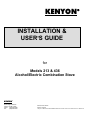
1
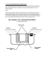
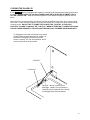
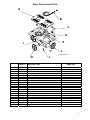
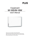
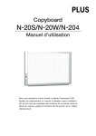
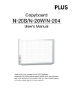
KENYON INSTALLATION & USER’S GUIDE for Models 213 & 436 Alcohol/Electric Combination Stove KENYON P.O. Box 925 #8 Heritage Park Road Clinton, CT 06413 USA Phone: (860) 664-4906 Fax: (860) 664-4907 Revision 07.20.05 Part # 141358 \Mrpserver\KENYON ENGINEERING\MANUALS\NP Alcohol\213 MANUALS\213 MANUAL INTRODUCTION Thank you for purchasing a KENYON Alcohol/Electric combination stove. The operation instructions that follow are for the models 213 (single burner) and 436 (double burner) alcohol/electric combination stoves. These units feature counter-top mounting, self-priming / self pressurized alcohol burners. The electric portion of the stove operates on 120 VAC (or 240 VAC depending on KENYON Model #). KENYON marine stoves have been engineered exclusively for the marine environment. Design considerations and materials were dictated by the requirement for safety, reliability, long life, low maintenance, and operation in a salt atmosphere. ! IMPORTANT : PLEASE READ THESE INSTRUCTIONS COMPLETELY BEFORE INSTALLATION AND OPERATION OF THE APPLIANCE DO NOT DISCARD THIS MANUAL. KEEP THIS MANUAL AND INSTRUCTIONS FOR FUTURE REFERENCE UNPACKING YOUR KENYON STOVE Carefully unpack your KENYON Stove from its shipping container. Do not discard the shipping carton or protective foam. It may be useful if your unit ever needs to be serviced. Verify and Identify Package Contents. The following items should be included in the carton: 1- Alcohol/Electric Stove 1- Fill Bottle 1- Installation and User’s Guide If any of these items are missing, please contact KENYON Customer Service at (860) 664-4906 or via e-mail: [email protected] VERIFY THE PROPER ELECTRICAL REQUIREMENTS The table on the following page displays the minimum electrical requirements for each model stove: The electric supply must be from an individual grounded circuit that is protected by a double pole simultaneous trip circuit breaker rated per the specifications for the various models as shown in the table on the following page. ! Warning: If the electric power supply provided does not meet the product specifications, call a licensed electrician before proceeding with installation. 2 KENYON Model # B61044 B61045 B61046 B61047 B61048 B61049 Stove Description Voltage AC Rated Wattage (W) & Amps (A) 213 A/E w/ Black Glass Lid 213 A/E w/ Black Glass Lid 213 A/E w/ White Glass Lid 213 A/E w/ White Glass Lid 436 A/E w/ Black Glass Lid 120 Volts - 60 Hz 1100 W / 10 A 240 Volts - 50/60 Hz 1100 W / 5 A 120 Volts - 60 Hz 1100 W / 10 A 240 Volts - 50/60 Hz 1100 W / 5 A 120 Volts – 60 Hz 2200 W / 20 A 436 A/E w/ Black Glass Lid 240 Volts - 50/60 Hz 2200 W / 10 A Suggested Wire Size Based On Wire Run Length - d (feet) One Way d < 35 feet : 14 AWG 35 < d < 80 feet: 12 AWG d < 125 feet: 14 AWG d < 35 feet : 14 AWG 35 < d < 80 feet: 12 AWG d < 125 feet: 14 AWG d < 20 feet: 14 AWG 20 < d < 45 feet: 12 AWG 45 < d < 70 feet: 10 AWG d < 90 feet: 14 AWG INSTALLATION INSTRUCTIONS NOTE: Installation should comply with ABYC standard A-3, “Recommended Practices and Standards Covering Galley Stoves,” and/or the “Fire Protection Standards for Motorcraft” NFPA #302. MOUNTING THE ALCOHOL COOKTOP LOCATING THE COOK TOP AWAY FROM FLAMMABLE MATERIALS Before you cut your countertop: Make certain the Cook Top will be far enough from flammable materials! ! CAUTION Do not cut the opening in your countertop until you ensure that there will be adequate horizontal and vertical clearances from the Cook Top to the nearest flammable materials- fabric, plastic, wood- (except the countertop itself). Minimum Distances are: 40cm (16”) Horizontally 1M (39”) Vertically It is the installer’s and/or purchaser’s responsibility to ensure that the Cook Top is installed in a location such that a fire hazard is not created. IN EUROPE: Contact the authorities appointed by the government in each separate country IN USA: Contact ABYC, 3069 Solomons Island Road, Edgewater Maryland 21037-1416 tel (410) 956 1050 fax (410) 956 2737 internet [email protected] 3 LOCATION & COUNTER-TOP PREPARATION The stove must be located in an area with adequate ventilation for occupants’ safety and efficient stove operation. It should be installed with adequate clearances between the stove top and all surrounding surfaces (i.e. curtains, cabinets, etc) in order to minimize heat transfer to these surfaces. Also fire resistant materials should be attached to any surrounding surfaces, especially overhead. Once a location for the stove has been chosen, it is important to check clearances underneath the counter for the bottom portion of the stove and its moving parts. The stove extends about 6 inches (152 mm) below the countertop. If drawers or cabinets are located under the stove, a rigid barrier must be installed to prevent combustible items, (i.e. rags, paper, etc.) from coming in contact with the hot stove. The barrier must be ventilated. Adequate ventilation of the space below the stove must be provided to ensure proper operation of the stove. Heat transferred from the cook top bottom pan during operation will overheat an improperly ventilated area. FAILURE TO PROVIDE PROPER CLEARANCES AND VENTILATION MAY RESULT IN A FIRE HAZARD. General dimensions for each model stove are shown below: 213 Model 12 3/4" 436 Model 13 1/2" 12 3/4" 22 1/2" 5 3/4" 5 3/4" 3" Radius 12 1/4" 12 1/4" 21 3/4" 12 3/4" Note: A 3" radius is required INSTALLATION Once the cutout has been prepared as shown on page 3, pre-fit the stove into the cutout to mark drill locations. Tilt and insert the front portion of the stove first. Care should be exercised so as not to damage or bend any moving parts. Next, lower the stove into the cut out. Using a pencil mark the location of mounting holes onto the counter. Carefully remove the stove from the cutout. Using a 1/8" drill and the pencil marks as a guide, drill four (4) mounting holes. Replace the stove into the counter. Mount the stove in place by using (4) #8 x 5/8" oval head stainless steel wood screws(not supplied). Electrical Connection It is recommended that the supply conductors be protected with a double pole simultaneous trip circuit breaker per the specifications for the various models and voltages as shown in the Electrical Requirements Table on page 3. Use SO rubber-insulated cable to connect the boat shore power electrical circuit to the terminal board in back of the stove. NOTE: Only qualified installers should connect this appliance to the electrical service. 4 Remove the back cover on the stove; push the cable through 7/8” (22 mm) hole below the terminal board, using the black plastic grommet to protect the supply cable. Connect the ungrounded current carrying conductor to terminal marked L1. Connect the other ungrounded current carrying conductor (or neutral carrying conductor- 120V only) to the terminal marked L2. Connect the ground wire (green) to the left terminal marked G. A cable clamp is provided to secure cable. Replace the back cover after all connections have been made. USER INSTRUCTION Safety This section must be read before operating your KENYON cook top. This safety instruction section covers all KENYON electric cook tops and stoves. PLEASE READ THIS ENTIRE MANUAL THOROUGHLY BEFORE OPERATING YOUR KENYON STOVE This stove, like all appliances, has the potential to create safety problems through careless or improper use. Please observe all of the following safety precautions. • Proper Installation- Be sure your appliance is properly installed and grounded by a qualified technician. • • Never use your appliance for warming or heating the room. Do Not Leave Children Alone-children should not be left alone or unattended in area where appliance is in use. They should never be allowed to sit or stand on any part of the appliance. • CAUTION: Do not store items of interest to children in cabinets above the stove- children climbing on the range/counter to reach items could be seriously injured. • Wear Proper Apparel- Loose-fitting or hanging garments should never be worn while using the appliance. • User Servicing- Do not repair or replace any part of the appliance unless specifically recommended in the manual. All other servicing should be referred to a qualified technician or KENYON Customer Service: (860) 664-4906. • Storage in or on Appliance- Flammable materials should not be stored near surface elements. • Do Not Store Plastic Utensils In Storage Drawer below the stove- if a storage drawer is located directly below the stove, plastic or other utensils with low melting temperatures should not be stored in the storage drawer. • Do Not Use Water on Grease Fires- Smother fire or flame or use dry chemical or foam-type extinguisher. • Use Only Dry Potholders- Moist or damp potholders on hot surfaces may result in burns from steam. Do not let potholders touch heating elements. Do not use a towel or other bulky cloth. 5 • DO NOT TOUCH HEATING ELEMENTS - Heating element areas may be hot even though they are dark in color. These areas may be hot enough to cause burns. During and after use, do not touch, or let clothing or other flammable materials contact heating element areas until heating elements have had sufficient time to cool. Other surfaces of the appliance may become hot enough to cause burns. • Servicing- Do not attempt to repair or replace any part of your KENYON stove. If service should be necessary, contact your local servicing dealer or KENYON Customer Service at (860) 664-4906. If the stove must be removed for servicing, turn the power off to the appliance before attempting to remove the unit ! WARNING OPEN FLAME COOKING APPLIANCES CONSUME OXYGEN AND PRODUCE CARBON MONOXIDE. TO AVOID ASPHYXIATION OR INJURY OR DEATH FROM EXPOSURE TO CARBON MONOXIDE, MAINTAIN OPEN VENTILATION WHEN USING THIS APPLIANCE. Do Not Throw Away These Instructions! 6 ALCOHOL BURNER OPERATING INSTRUCTIONS Before attempting to operate the stove, please read the theory and operating instructions carefully and become thoroughly familiar with the various parts of the stove and how they operate. An internal parts diagram has been provided below to illustrate burner functions and characteristics under normal operating conditions. Theory This patented burner system incorporates an internal tank in the burner assembly that does not require any external pressurization. This burner system uses ethyl alcohol. The “center chimney” contains a fiber wick, which is lit to start the burner. The flame from the wick, vaporizing and pressurizing the alcohol inside rapidly heats a separate surrounding chamber, within the burner. A ring of holes (burner jets) in the top of this vaporization chamber allows the escape of the alcohol vapor which is ignited by the central flame. The central flame than diminishes and the burner functions in the normal manner. SELF-PRIMING / SELF PRESSURIZED BURNER Cross Sectional View Burner Jets Air Flow Center Chimney Wick Air Flow Surrounding Chamber 7 Operating Components A Fill Cap is located on each burner with a rubber washer (gasket) underneath each fill cap. Be sure the washer is in place and the fill cap is reasonably tight when operating the stove. If either are lost or damaged replace at once. DO NOT ATTEMPT TO OPERATE THE BURNER WITHOUT A CAP OR WITH ANY NON COMPATIBLE REPLACEMENT. The alcohol burner control wheel(s) are located in the front flange of the stove. The purpose of the control wheel is to regulate the burner flame. With the control wheel positioned to the extreme right, the flame control cap (snuffer) will completely cover the burner ports (jets). With the control wheel positioned to the extreme left, the burner ports will be completely exposed. Other variations of the control wheel position will allow for flame adjustment between maximum and minimum heat output. WARNING ! IMPROPER STOVE FUELING PRACTICES CAN RESULT IN FIRE AND/OR EXPLOSION. TO AVOID SEVERE INJURY OR DEATH FROM FIRE OR EXPLOSION, FOLLOW THE MANUFACTURER’S REFUELING INSTRUCTIONS THAT ARE PRINTED IN YOUR MANUAL AS WELL AS ON THE STOVE. Alcohol Burner Fueling Instructions 1. The burners are designed exclusively for denatured ethyl alcohol which is readily available as "alcohol stove fuel" at marine stores. DO NOT SUBSTITUTE ANY OTHER FUEL AS FIRE OR EXPLOSION COULD RESULT. A Denatured ethyl alcohol fire is readily extinguished by water, or by smothering it with a non-combustible material. 2. Before attempting to fuel the stove, be sure that the burners are not in operation and that all flame and other sources of ignition in the galley area are extinguished. Make sure the stove is cool before fueling. 3. The alcohol control wheel(s) located in the front of the appliance must be in the off position (rotate completely to the right) which places the flame control cap completely over the burner ports. The air deflector assembly is equipped with an interlock. If the control cap is not over the burner ports, the deflector can not be removed to access the fill cap. 4. Carefully rotate electric element assembly up and remove the air deflector assembly to access the fill cap. If the electric element was operated recently, DO NOT PROCEED UNTIL THE ELEMENT HAS COOLED. Failure to do so could result in severe burns or injury. 5. Be aware that an alcohol flame is invisible in sunlight. If the stove has been operated recently, be particularly careful to make sure that all burner flames are extinguished and the burner is cool. DO NOT PROCEED UNTIL FLAMES ARE EXTINGUISHED AND THE BURNER HAS COOLED. 6. Remove the fill cap and fill the burner(s) slowly with denatured ethyl alcohol, six (6) ounces only. The burner fuel storage tank is designed to readily accept the proper amount of fuel and discourage overfilling. Do not attempt to fill with more fuel that can be readily poured in. Six (6) ounces will be enough to moisten the primary wick and provide the ideal conditions for proper function of the alcohol burner. More than six ounces may cause the chimney to flood. A flooded chimney will cool the surrounding chamber and the burner will not operate as intended. (Refer to theory of Operation) With this stove, a six ounce fill bottle is supplied. Using the supplied fill bottle each time will prevent overfilling since the fill bottle's volume is the same size as burner's storage tank. 7. Replace the fill cap, making sure the rubber washer (gasket) is in place and that the fill cap is securely tightened. 8 8. Wipe any alcohol spills and replace the air deflector assembly into the pan and return the electric element back into place. Note that the electric element serves as a grate when using the alcohol burner to cook. Alcohol Burner Operating Instructions 1. Completely open the flame control cap by rotating the control wheel to the left. 2. Ignite the small fiber wick located in the center chimney. A match may be used or a Bar-B-Que grilligniting wand is ideal. Do not leave matches in the center chimney; they will inhibit the efficiency of the burner. 3. Allow for approximately two minutes to five minutes for flames to appear in the burner jets (see theory of operation) Cooking may be initiated immediately after ignition of the center chimney. This will not effect the preheating of the main burner and automatic switch over to normal full operation. ELECTRICAL OPERATION Controls are located in the rim of the frame: for alcohol burners, the controls are located in the front of the appliance; for electric elements, the controls are located in the sides as shown below in the figure. WARNING: NEVER OPERATE ALCOHOL BURNER(S) AND ELECTRIC ELEMENT(S) SIMULTANEOUSLY. THIS CAN CAUSE FIRE OR SEVERE INJURY Operation of Electric Elements Turn the electric control in either direction to HIGH, LOW, or any intermediate position for exact heat desired. A Pilot Indicator light, one for each element, stays ON until the electric control is turned to the OFF position. When finished cooking, make sure both pilot lights are out and that the electric controls are in the OFF position. Pilot Indicator Light Electric Element Control Wheel 436 Model Shown Alcohol Burner Control Wheel Turning alcohol control wheel to the left will provide maximum flame output Turning alcohol control wheel to the right will lower flame output or extinguish (“snuff”) flame Turn Electric Control Wheel in either direction to HIGH, LOW, or any intermediate position for electric element operation. 9 CLOSING THE GLASS LID If your KENYON stove is equipped with a glass lid, care should be followed when lowering the lid onto the stove. NEVER CLOSE THE LID ON AN OPEN FLAME OR AN ELECTRIC ELEMENT THAT IS HOT OR TURNED “ON”. Make sure that the appliance is cool before lowering the glass lid onto the frame. When the lid is in an open position, the “lid-stay” arm that is attached to the glass “locks” onto the large lock screw. In order to lower the glass lid onto the stove frame, the “lid-stay” must be unlocked from the mounting screw. DO NOT TRY TO LOWER THE LID WITH THE “LID-STAY” IN THE LOCK POSITION. FAILURE TO UNLOCK THE “LID-STAY” WHEN ATTEMPTING TO LOWER THE GLASS LID CAN CAUSE DAMAGE TO THE APPLIANCE WHICH IS NOT COVERED UNDER WARRANTY. To disengage lid from the lock position, fully extend (rotate lid back) lid back and gently lift “lid-stay” up as shown to disengage from the lock position. Once the “lid-stay” is in the unlock position, the lid can be lowered to the close position. “LID-STAY” Lock Screw Gently lift “lid-stay” up as shown to disengage “lid-stay” from lock position. Carefully lower the glass lid once “lid-stay” is disengaged from the lock position. 10 Stove Replacement Parts A B H G C D E I L F K A B C D E F G H I J K L not shown not shown not shown 436 Model Shown J PART # DESCRIPTION B93077 B93075 240360 H2003-1 H1950 240385 B93090 240342 B93086 B93087 043200 240338 240400 240407 141485 141580 H1947-1 H1947-2 240378 240403 240405 Air Deflector Assembly Air Deflector Assembly Electric Element Assembly- 120 Volts Electric Element Assembly- 240 Volts Indicator Light- 120 Volts Indicator Light- 240 Volts Fill Cap w/ Rubber Washer Gasket Non Pressurized Burner Assembly Electric Control Switch- Infinite Control- 120 Volts Electric Control Switch- Infinite Control- 240 Volts Lid Safety Switch Snuffer Control Arm Assembly Control Baffle Assembly- 213 Control Baffle Assembly- 436 Electric Thermostat Alcohol (NP) Control Wheel Electric Control Wheel- Left Electric Control Wheel - Right 213 Black Glass Assembly 213 White Glass Assembly 436 Black Glass Assembly USED ON All 436 Models All 213 Models 120 Volt Models 240 Volt Models 120 Volt Models 240 Volt Models 213 & 436 Models 213 & 436 Models 120 Volt Models 240 Volt Models 213 & 436 Models 213 & 436 Models 213 Models 436 Models 213 & 436 Models 213 & 436 Models 213 & 436 Models 436 models 213 BG 213 WG 436 BG 11 WARRANTY Kenyon International, Inc (the "Company") warrants its products in normal usage to be free of defects in materials and workmanship subject to the conditions and limitations below. Any part, which proves to be defective in normal usage during the warranty period will be repaired or replaced by the Company. This warranty is subject to the following conditions and limitations: 1. The Company's liability shall be limited to repair or replacement (choice of remedy at Company's option) of goods or parts as may be defective in materials or workmanship. This liability is limited to two years from the date of original installation; this warranty covers parts and labor at approved Company rates. 2. Determination of suitability of the product for the use contemplated by the buyer is the sole responsibility of the buyer and the Company shall have no responsibility in connection with such suitability. 3. The Company shall not be liable for any damage resulting from: • failures due to use of the product in applications for which they are not intended • failures due to corrosion, wear and tear, abuse or improper installation or maintenance 4. The Company shall be responsible for ground shipping charges to the location of the appliance (home) within the continental United States and Canada. Any other or express or special shipping charges are at the expense of the buyer. 5. All labor allowed by the Company under this warranty must be performed by an authorized Kenyon International service center, unless otherwise specified in writing by the Company. THERE ARE NO OTHER WARRANTIES OF MERCHANTIBILITY, FITNESS FOR PURPOSE OR ANY OTHER KIND, EXPRESSED OR IMPLIED AND NONE SHALL BE IMPLIED BY LAW. The duration of any such warranties that are nevertheless implied by law for the benefit of a consumer, shall be limited to a period of two years from original purchase by the user. Some countries do not allow limitations on how long an implied warranty lasts, so this limitation may not apply to you. THE COMPANY SHALL NOT BE LIABLE FOR CONSEQUENTIAL OR INCIDENTAL DAMAGES ARISING FROM THE BREACH OF THIS WARRANTY, WHETHER EXPRESS, IMPLIED OR STATUTORY. Some countries or states do not allow exclusion or limitation of consequential or incidental damages so this limitation or exclusion may not apply to you. THIS WARRANTY GIVES YOU SPECIFIC LEGAL RIGHTS AND YOU MAY ALSO HAVE OTHER LEGAL RIGHTS THAT MAY VARY FROM COUNTRY TO COUNTRY AND STATE TO STATE. Kenyon International, Inc. P.O. Box 925 • 8 Heritage Park Road • Clinton, CT USA Phone (860) 664-4906 FAX: (860) 664-4907 Email: [email protected] 12