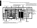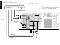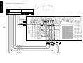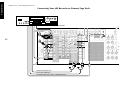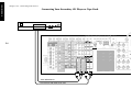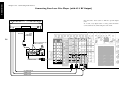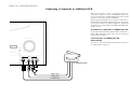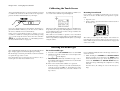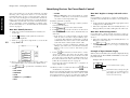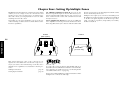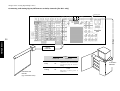
1
KRF-X9995D
i
B60-4885-10 02 CH (M, T, X) OC 0011
Before Applying Power
Read this section carefully to ensure safe operation.
KRF-X9995D is designed for operation as follows.
U.K. and Europe ................................... AC 230 V only
Australia ................................................ AC 240 V only
*Other countries
................................ AC 110-120/220-240 V switchable
*For other countries
AC voltage selection
The AC voltage selector switch on the rear panel is set to the
voltage that prevails in the area to which the unit is shipped.
Before connecting the power cord to your AC outlet, make
sure that the setting position of this switch matches your
line voltage. If not, it must be set to your voltage in accordance with the following direction.
Note:
Our warranty does not cover damage caused by excessive
line voltage due to improper setting of the AC voltage selector switch.
AC voltage selector switch
AC 110–120V/220–240V
50/60Hz SWITCHED
TOTAL 90W MAX.
AC 110 –
120V
AC 220 –
240V
Move switch lever to match your line voltage with a small
screwdriver or other pointed tool.
For United Kingdom
ii
Factory fitted moulded mains plug
1. The mains plug contains a fuse. For replacement, use
only a 13-Amp ASTA-approved (BS1362) fuse.
2. The fuse cover must be refitted when replacing the
fuse in the moulded plug.
3. Do not cut off the mains plug from this equipment.
If the plug fitted is not suitable for the power points
in your home or the cable is too short to reach a
power point, then obtain an appropriate safety approved extension lead or adapter, or consult your
dealer.
If nonetheless the mains plug is cut off, remove the
fuse and dispose of the plug immediately, to avoid a
possible shock hazard by inadvertent connection to
the mains supply.
IMPORTANT : The wires in the mains lead are coloured
in accordance with the following code:
Blue
: Neutral
Brown : Live
Do not connect those leads to the earth terminal of a
three-pin plug.
Safety Precautions
Read this section carefully to ensure safe operation.
WARNING :
TO PREVENT FIRE OR ELECTRIC SHOCK, DO NOT EXPOSE THIS APPLIANCE
TO RAIN OR MOISTURE.
CAUTION: TO REDUCE THE RISK OF ELECTRIC SHOCK, DO
NOT REMOVE COVER (OR BACK). NO USER-SERVICEABLE
PARTS INSIDE. REFER SERVICING TO QUALIFIED SERVICE
PERSONNEL.
THE LIGHTNING FLASH WITH ARROWHEAD SYMBOL, WITHIN AN EQUILATERAL TRIANGLE,
IS INTENDED TO ALERT THE USER TO THE PRESENCE OF UNINSULATED “DANGEROUS
VOLTAGE” WITHIN THE PRODUCT’S ENCLOSURE THAT MAY BE OF SUFFICIENT MAGNITUDE TO CONSTITUTE A RISK OF ELECTRIC SHOCK TO PERSONS.
THE EXCLAMATION POINT WITHIN AN EQUILATERAL TRIANGLE IS INTENDED TO ALERT
THE USER TO THE PRESENCE OF IMPORTANT OPERATING AND MAINTENANCE (SERVICING) INSTRUCTIONS IN THE LITERATURE ACCOMPANYING THE APPLIANCE.
Connecting and Setting Up Your New Kenwood Audio-Video Receiver
Welcome to the Connection and Setup Guide for your new
Kenwood audio-video receiver.
The KRF-X9995D offers 3 kinds of 5.1-channel digital decoding:
•
Dolby Digital, for the hundreds of currently available
Dolby Digital DVDs and LaserDiscs.
•
DTS, a well-established multichannel format in movie
theaters, is available for home theater on LaserDisc and
DVD.
•
MPEG Multichannel, a well-established multichannel
format in movie theaters, is available for home theater
on LaserDisc and DVD.
The KRF-X9995D also offers 2 kinds of 6.1-channel digital
decoding:
•
•
THX Surround EX technology reproduces a surround
back channel from software which has been specially
encoded with Surround EX.
DTS-ES also creates a 6.1-channel surround environment
by adding the surround back signals. The KRF-X9995D
can handle both DTS-ES Discrete 6.1 featuring recording
of all channels in the digital discrete format and DTSES Matrix 6.1 featuring matrix encoding.
Use it to connect all your current audio and video components—the KRF-X9995D has a variety of connection jacks
so you can customize your entertainment setup.
It also includes Kenwood’s remarkable PowerTouch LCD
remote—a graphical user interface without having to use
your TV!
Other advanced features include 6 S-Video inputs and an
optical and coaxial digital outputs for digital dubbing to
MiniDisc or CD-R. For a match made in “dual-room
heaven,” get the DPF-J9030, DPF-J9020 or DPF-J9010
changer.
D.R.I.V.E. circuit: This is a Kenwood original technology for
reproducing signals with high resolution by instant switching of the internal filters according to the input signal. The
KRF-X9995D incorporate a high performance DSP to provide very high resolution from a 32-bit DRIVE III circuit,
achieving stereo audio reproduction with the best quality
ever reached.
HDCD®: This is a new format of high-resolution recording.
The KRF-X9995D is capable of reproducing CDs recorded
in the HDCD format with high resolution and wide dynamic
range.
Manufactured under license from Digital Theater Systems,
Inc. US Pat. No. 5,451,942, 5,956,674, 5,974,380, 5,978,762
and other world-wide patents issued and pending. “DTS”,
“DTS-ES Extended Surround” and “Neo:6” are trademarks
of Digital Theater Systems, Inc.Copyright 1996, 2000 Digital Theater Systems, Inc. All Rights Reserved.
iii
Lucasfilm and THX are registered trademarks of Lucasfilm
Ltd.
©Lucasfilm Ltd. & TM. All rights reserved. Surround EX is a
jointly developed technology of THX and Dolby Laboratories Inc. and is a trademark of Dolby. Used under authorization.
In addition, the KRF-X9995D offers the following surround
features.
•
DTS-NEO:6: This converts 2-channel signals into 6.1channel signals by means of a high-accuracy digital
matrix decoder.
•
Dolby Pro Logic II: This is advanced version of Dolby
Pro Logic and features improved audio quality.
•
THX Ultra: This corrects signals in order to reproduce a
similar acoustic field to movie theaters in home use.
Manufactured under license from Dolby Laboratories.
"Dolby", "Pro Logic", "Surround EX " and the double-D symbol are trademarks of Dolby Laboratories. Confidential unpublished works. Copyright 1992-1997 Dolby Laboratories.
All rights reserved.
, HDCD®, High Definition Compatible Digital® and
Pacific MicrosonicsTM are either registered trademarks or
trademarks of Pacific Microsonics, Inc. in the United States
and/or other countries. HDCD system manufactured under
license from Pacific Microsonics, Inc. This product is covered by one or more of the following: IN the USA: 5,479,168,
5,638,074, 5,640,161, 5,808,574, 5,838,274, 5,854,600,
5,864,311, 5,872,531, and in Australia: 669114. Other patents pending.
CHANNEL SPACE / DEEMPHASIS Switch
Area
CHANNEL
SPACE freq.
DEEMPHASIS
USA, Canada,
1 and South
American
Countries
FM : 100 kHz
AM : 10 kHz
75 µs
2 Other
Countries
FM : 50 kHz
AM : 9 kHz
50 µs
Not present for U.K. and Australia
The above are additional trademarked names appearing in
this manual. All other products named are trademarks of
their respective companies.
iv
The CHANNEL SPACE/ DE-EMPHASIS switch on the rear
panel is set to the correct setting that prevails in the area to
which the unit is shipped. However, if the CHANNEL
SPACE/ DE-EMPHASIS setting is not matched to the area
where the unit is to be used; for instance, if you move from
area 1 to area 2 as shown in the table to the right or vice
versa, desired reception of AM/ FM broadcasts is not expected. In this case, change the CHANNEL SPACE/ DEEMPHASIS setting in accordance with the area corresponding to the table. The CHANNEL SPACE/ DE-EMPHASIS is
switched over at the same time.
•
When changing the setting of the CHANNEL SPACE/
DE-EMPHASIS switch, first unplug the power cord, and
then reset the switch, plug the power cord back in, and
turn the power switch on.
CHANNEL SPACE
DE-EMPHASIS switch
GND
AM
ANTENNA
50 µs
AM 9kHz
FM 50kHz
75 µs
AM 10kHz
FM 100kHz
DE-EMPHASIS
CHANNEL SPACE
Unpacking
Unpack your new receiver carefully and make sure that all the accessories are present:
Remote control unit
(PowerTouch)
Batteries
AA (R6) × 6
AM Loop Antenna
FM Antenna
AC plug adapter
ENTER
VO
LU
UP
CONFIRM
M
E
DOWN
CONTRAST
ON/STANDBY
REMOTE OFF
If any accessories are missing, or if the receiver is damaged or fails to operate, notify your dealer immediately. If your receiver was shipped to you
directly, notify your shipper immediately. Kenwood recommends that you retain the original carton and packing materials in case you need to
move or ship the receiver in the future.
Use to adapt the plug on the power
cord to the shape of the wall outlet.
(Present only for regions where use
is necessary.)
Table of Contents
Chapter One: Connecting Your Devices .... 1
Noting Your Devices .............................................. 3
Connecting Your Speakers .................................... 4
To Connect Front Speakers Only
To Connect Front and Surround Sound
Speakers
What if I Have a Powered Subwoofer?
To Connect Surround Back Speaker
To Connect a Kenwood 200-Disc CD
Changer
To Connect Any Other Primary CD Player or
Changer
To Connect a Secondary CD Player
Connecting Your DVD Player .............................. 18
To Connect a DVD Player
Connecting Your CD-R Recorder ........................ 20
To Connect a CD-R Recorder
What if I Have an Amplifier? ................................. 8
Connecting Your TV ............................................ 10
To Connect a TV
What if I Want to Watch TV without Turning
on the Receiver?
Connecting Your Cable TV or Satellite Tuner ..... 12
To Connect a Cable TV Tuner with a
Composite (RCA) Video Output
To Connect a Cable TV Tuner without a
Composite (RCA) Video Output
To Connect a Satellite Tuner
Connecting Your VCR(s) ..................................... 14
To Connect a Primary VCR
To Connect a Secondary VCR
Connecting Your Primary CD Player .................. 16
What if I Have a Video CD-Compatible CD
Player?
Connecting Your MD Recorder or Primary
Tape Deck ......................................................... 22
To Connect an MD Recorder
To Connect a Primary Tape Deck
To Connect a Secondary Tape Deck
Connecting Your Secondary CD Player or
Tape Deck ......................................................... 24
To Connect a Secondary CD Player
To Connect a Secondary Tape Deck
Connecting Your Laser Disc Player
(with AC-3 RF Output) ..................................... 26
To Connect an AC-3 RF Output Laser Disc
Player
Connecting Your Turntable/Record Player ......... 30
To Connect a Turntable/Record Player
Connecting a Camcorder or Additional VCR ..... 31
To Connect a Camcorder or Additional VCR
Can I Connect an Additional VCR Permanently?
What if I Have Several Kenwood Devices (System
Control Chaining)? .......................................... 32
Connecting the Antennas .................................... 33
AM Loop Antenna
FM Indoor Antenna
FM Outdoor Antenna
What if I Have Cable Radio?
Chapter Two: Setting Up PowerTouch ... 34
Installing the Batteries ........................................ 34
Calibrating the Touch Screen .............................. 35
Resetting PowerTouch
Selecting the Model Type .................................... 35
Navigating PowerTouch Interface ....................... 36
Connecting Your Laser Disc Player
(without AC-3 RF Output) ............................... 28
To Connect a PCM Digital Output Laser Disc
Player
v
Table of Contents
Setting Up Speakers ............................................ 37
Speaker Placement
SP Selection
SP Distance
SP Level
Bass Peak Level
Identifying Devices For PowerTouch Control ..... 40
How Do I Identify Devices?
How Do I Replace a Setup Code with a New
One?
How Do I Delete Setup Codes?
Example of device button display
vi
Storing Radio Stations in Memory (optional) ... 41
Storing RDS Stations Automatically
(for U.K.only)
Storing RDS Stations Name (PS Read)
(for U.K.only)
Storing Stations Manually
To Customize the PowerTouch Screen ................ 43
Changing the Name
Changing the Item Size
Moving an Item
Cutting an Item
Copying an Item
Pasting an Item
Deleting an Item
Selecting an Item in the Gallery and Pasting
it in the Screen
Programming a Function in a Button (Learn)
Resetting to Default
Switching the Customized Screen to another
(Jump)
To Undo the Last Operation Performed
Locking Customization Results with a
Password
Chapter Three: Setting Up on the Receiver
............................................................. 46
Speaker Setup
Storing Radio Stations in Memory (optional)
Chapter Four: Setting Up Multiple Zones
............................................................. 48
Making Connections ........................................... 49
Scenario 1: Surround Sound in Zone A only/
Stereo in Zone A and Stereo in Zone B
(Using the Receiver’s Speaker B Outputs)
Scenario 2: Surround Sound in Zone A and
Stereo in Zone B (Using a Stereo Amplifier
in Zone B)
Both Scenarios: Connecting a Second TV/
Monitor
Setting Up the PowerTouch ................................. 50
Connecting the External Infrared Receivers (for
U.K.only) .......................................................... 51
To Connect IR Receivers (IR Transceivers)
Connecting and Setting Up On/Off Sensors or
Relay Controls (for U.K.only) .......................... 52
To Connect Relay Controls
To Connect TV ON/OFF Sensors
Chapter Five: Specifications .................. 55
KRF-X9995D (for U.K.)
KRF-X9995D (for Other Countries)
Connections
Chapter One : Connecting Your Devices
Chapter One: Connecting Your Devices
Welcome to the Kenwood KRF-X9995D Connection and
Setup Guide. This chapter guides you through connecting
your home entertainment devices to your new Kenwood
audio-video receiver.
Once all your devices are connected, you can set up the
PowerTouch (see Chapter Two).
Refer to the following pages for details on connecting these
devices:
Speakers
TV
VCR(s)
CD Player, Kenwood 200-Disc Changer
DVD Player
CD-R Recorder
MD Recorder
Tape Deck(s)
Laser Disc Player
Turntable
Camcorder/Second VCR
Antennas
page 4
page 10
page 14
page 16
page 18
page 20
page 22
page 22
page 26
page 30
page 31
page 33
All necessary cables should be provided with your home
entertainment device (not with your new receiver). If you
do not have the correct cables, you may purchase these
cables from any home entertainment store.
To make coaxial digital connections, be sure to use a highquality digital audio cable, not a standard audio cable.
Do not plug in the receiver or any other device to AC power
until all connections have been made. Once all devices have
been connected, you may plug them in and provide power.
Important:
•
Component video connections provide the best video
quality; S-Video connections provide video quality that
is superior to standard composite video connections.
We recommend using the highest quality connection
possible between the receiver and your TV.
•
Since component video inputs are not downconverted
to S-Video or composite video, if you want to record
components connected via component video inputs you
must also connect that component's S-Video or composite video outputs to the receiver.
•
If you plan on using the KRF-X9995D in a Dual-Zone
application (see Chapter Four), you must use the composite video connections in addition to any component
video and S-Video connections for all source components. Only video sources connected to the receiver with
composite video connections can be viewed in the second zone.
Be sure to adhere followings, or proper ventilation will be
blocked causing damage or fire hazard.
Do not place any objects impairing heat radiation onto the
top of unit.
Leave a space around the unit (from the largest outside dimension including projection) equal or greater than, shown
below.
Top panel : 50 cm
Side panel : 10 cm
Back panel : 10 cm
Do not install your receiver where direct sunlight or high frequency fluorescent lighting can shine directly into the remote
sensor. This can cause your new receiver to malfunction.
Before You Begin
This manual covers the most common and standard connections to the receiver. Because of its versatility, you may
decide to connect your devices differently.
Video Connections
This receiver incorporates Kenwood's exclusive Universal
Video HD, which converts between composite, S-Video and
component video formats. This simplifies operation, and
maintains the highest possible video quality while requiring only a single connection between the receiver and your
TV. Video format conversion is performed according to the
following chart:
Video input signal type
Appears at these video outputs
1 Composite Video
Composite
S-Video
Component Video
Composite
S-Video
Component Video
Component Video
2 S-Video
3 Component Video
If several video connections are made, one of them will be
selected based on the priority 3, 2, and 1.
1
Connections
Chapter One : Connecting Your Devices
The following diagram shows the entire back of the KRF-X9995D.
Note that some component jacks are linked to specific digital jacks. For example, if you connect a video
component with a digital optical cable, you should connect the analog cables to the VIDEO2 video component
jacks and the digital cable to the VIDEO2 digital optical
jack.
Supplemental infrared receiver System control jacks
and sensor jacks, DVD control
jacks**, RELAY CONTROL jack
Pre out jacks and TV ON/OFF SENSOR jack
(for U.K. only)
Zone B pre out jacks
IR RECEIVER IR OUT DVD CONTROL IR RECEIVER IR OUT RELAY TV ON/OFF SL16 TEXT SYSTEM
IN
IN
LCD CONTROL SENSOR
CONTROL
LCD
R
L
ZONE B PRE OUT
VIDEO
DIGITAL OUT
SUB WOOFER CENTER
COMPONENT VIDEO
Y
R SURROUND BACK L R SURROUND L
R FRONT L
PRE OUT
S VIDEO
VIDEO
R AUDIO L
REC
OUT
VIDEO
3 IN
DVD
IN
Y
VIDEO
2
MONITOR
OUT
PLAY
IN
VIDEO3
PLAY
IN
VIDEO4
Y
PB/CB
VIDEO
4
PR/CR
MONITOR
OUT
50 µs
AM 9kHz
FM 50kHz
75 µs
AM 10kHz
FM 100kHz
DE-EMPHASIS
CHANNEL SPACE
CD-R
SURROUND
PLAY
IN
Video component
RS-232C
jacks
connector*
Digital jacks
(coaxial and optical)
SURROUND
SPEAKERS
(6–16Ω)
AC 110 –
120V
AC 220 –
240V
L
A FRONT SPEAKERS B
(6–16Ω)
R
PLAY
IN
REC
OUT
DVD/
6CH.
INPUT
CENTER
AC 120V 60Hz
SWITCHED TOTAL
90W 0.75A MAX.
R
PLAY
IN
REC
OUT
CD2/
TAPE2
MONITOR
DVD FRONT
PLAY
IN
AM
MD/
TAPE1
VIDEO2
PLAY
IN
PR/CR
OPTICAL
COAXIAL
DIGITAL IN
GND
ANTENNA
REC
OUT
CD-R
VIDEO
3
FM 75Ω
CENTER
SPEAKER
(6–16Ω)
C
REC
OUT
PB/CB
EXT.CONTROL
RS-232C
A
CD1
PR/CR
MD/
TAPE1
DC12V 20mA REMOTE DC12V 20mA DC5V 10mA
PLAY
IN
DVD
CD1
B
R AUDIO L
PHONO
VIDEO1
PB/CB
2
DC12V REMOTE
20mA
L
SUBWOOFER
Audio component jacks
Channel space/FM deemphasis switch
(only for some areas)
Antenna jacks
* The RS-232C connector is provided for future capability (to connect a commercially marketed
controller having the capability of controlling the KRF-X9995D).
** The DVD CONTROL jacks are reserved for future extension of the system.
Speaker wire
binding post
AC Plugs
The shape of
plugs are
different between
countries
AC voltage
selector switch
(only for some
areas)
Connections
Chapter One : Connecting Your Devices
Noting Your Devices
Jack Set
Device
Manufacturer
Model #
Setup Code
PHONO
CD1
MD/TAPE1
CD2/TAPE2 MONITOR
CD-R
MONITOR OUT
(TV on PowerTouch)
3
VIDEO1
VIDEO2
VIDEO3
VIDEO4
DVD
Use this table and the diagram on the preceding page to
plan your connections before you make them, or use it to
record your connections as you make them.
You will need this information later, when you set up your
PowerTouch (see “Identifying Devices For PowerTouch Control” on page 40). Recording this information now will save
you additional trips behind your home entertainment cabinet. You will fill in the Setup Code column when you are
setting up PowerTouch.
When playing Dolby Digital* or DTS-encoded software in
multichannel configuration, the connected audio signal
should be the digital signal.
* When playing a LaserDisc recorded in the Dolby Digital
format, connect the AC-3 RF output to the receiver (See page
26).
Connections
Chapter One : Connecting Your Devices
Connecting Your Speakers
L
SURROUND
R
SURROUND
R
FRONT
CENTER
IR RECEIVER
IN
R
L
ZONE B PRE OUT
VIDEO
4
DIGITAL OUT
SUB WOOFER CENTER
COMPONENT VIDEO
Y
R SURROUND BACK L R SURROUND L
R FRONT L
PRE OUT
S VIDEO
VIDEO
R AUDIO L
REC
OUT
VIDEO
3 IN
DVD
IN
Y
MD/
TAPE1
VIDEO2
PLAY
IN
PLAY
IN
REC
OUT
CD2/
TAPE2
MONITOR
PB/CB
PLAY
IN
VIDEO3
PLAY
IN
VIDEO4
PR/CR
VIDEO
2
MONITOR
OUT
Y
PB/CB
VIDEO
4
OPTICAL
COAXIAL
DIGITAL IN
PR/CR
MONITOR
OUT
A
FM 75Ω
GND
AM
DVD/
6CH
INPUT
CD-R
SURROUND
PLAY
IN
CENTER
50 µs
AM 9kHz
FM 50kHz
75 µs
AM 10kHz
FM 100kHz
CENTER
SPEAKER
(6–16Ω)
C
DE-EMPHASIS
CHANNEL SPACE
AC 120V 60Hz
SWITCHED TOTAL
90W 0.75A MAX.
R
SURROUND
SPEAKERS
(6–16Ω)
AC 110 –
120V
AC 220 –
240V
L
A FRONT SPEAKERS B
(6–16Ω)
R
PLAY
IN
REC
OUT
DVD FRONT
PLAY
IN
DC12V 20mA REMOTE DC12V 20mA DC5V 10mA
ANTENNA
REC
OUT
REC
OUT
CD-R
VIDEO
3
B
R AUDIO L
CD1
PR/CR
EXT.CONTROL
RS-232C
DC12V IR OUT LCD
20mA REMOTE
PLAY
IN
DVD
MD/
TAPE1
DVD CONTROL IR RECEIVER IR OUT RELAY TV ON/OFF SL16 TEXT SYSTEM
IN
LCD CONTROL SENSOR
CONTROL
PHONO
VIDEO1
PB/CB
CD1
L
FRONT
SUBWOOFER
L
Connections
Chapter One : Connecting Your Devices
Connecting Your Speakers, continued
Do not plug in the receiver to AC power until all connections have been made.
To Connect Front and Surround Sound
Speakers:
To Connect Front Speakers Only:
To listen to the full surround sound that this receiver can
put out, connect front speakers, center, left surround, and
right surround speakers. To do so:
If you only intend to listen to stereo sound (as opposed to
surround sound), you may simply connect a single pair of
speakers. To do so:
Using Banana Plugs (except for U.K.):
1. Tighten the speaker wire binding posts. If you do not
tighten the posts, they will not conduct sound properly
to the speakers.
To reproduce more enriched bass, connect a subwoofer
incorporating a power amplifier.
Using Banana Plugs (except for U.K.):
1. Tighten the speaker wire binding posts. If you do not
tighten the posts, they will not conduct sound properly
to the speakers.
3. Repeat step 2 for the positive and negative wires on the
LEFT FRONT speaker.
2. Follow the steps under “To Connect Front Speakers
Only” on this page to connect the RIGHT and LEFT
FRONT speakers.
1. Loosen the speaker wire binding posts.
2. Insert the wire from the positive jack on the RIGHT
FRONT speaker into the U-shaped slot in the base of
the positive RIGHT FRONT post. Lay the wire to the
right of the post; that way, when you tighten the binding post, it will naturally twist the wire into the best
connection. Tighten the post. Repeat for the negative wire
on the RIGHT FRONT speaker as shown to the right.
3. Repeat step 2 for the positive and negative wires on the
LEFT FRONT speaker.
5. Repeat step 4 for the positive and negative wires on the
LEFT SURROUND speaker.
For the connections of the subwoofer and surround back
speakers, see page 6 to 7.
2. Insert the plug from the positive jack on the RIGHT
FRONT speaker into the pin jack on the positive RIGHT
FRONT post. Repeat for the negative plug.
Using Bare Wires:
4. Insert the wire from the positive jack on the RIGHT SURROUND speaker into the U-shaped slot on the base of
the positive RIGHT SURROUND post. Tighten the post.
Repeat for the negative wire.
Never short circuit the + and - speaker wires.
Do not switch the left and right speaker wires or swap the +
and - wires on the binding posts.
The speakers must have a nominal impedance of between
6Ω and 16Ω.
5
3. Insert the plug from the positive jack on the CENTER
speaker into the pin jack on the positive CENTER post.
Repeat for the negative plug.
4. Insert the plug from the positive jack on the RIGHT
SURROUND speaker into the pin jack on the positive
RIGHT SURROUND post. Repeat for the negative plug.
5. Repeat step 4 for the positive and negative wires on the
LEFT SURROUND speaker.
Using Bare Wires
Using Bare Wires:
1. Loosen the speaker wire binding posts.
1. Loosen post
2. Follow the steps under “To Connect Front Speakers
Only” on this page to connect the RIGHT and LEFT
FRONT speakers.
3. Insert the wire from the positive jack on the CENTER
speaker into the U-shaped slot in the base of the positive
CENTER post as shown to the right.
2. Insert wire
Tighten the post. Repeat for the negative wire.
3. Tighten post
Connections
Chapter One : Connecting Your Devices
Connecting Your Speakers, continued
R
SURROUND
BACK
L
SURROUND
BACK
POWERED
SUBWOOFER
Power Amp.
6
IR RECEIVER IR OUT DVD CONTROL IR RECEIVER IR OUT RELAY TV ON/OFF SL16 TEXT SYSTEM
IN
IN
LCD CONTROL SENSOR
CONTROL
LCD
R
L
ZONE B PRE OUT
VIDEO
DIGITAL OUT
SUB WOOFER CENTER
COMPONENT VIDEO
Y
R SURROUND BACK L R SURROUND L
R FRONT L
PRE OUT
S VIDEO
VIDEO
R AUDIO L
REC
OUT
CD1
REC
OUT
REC
OUT
Y
MD/
TAPE1
VIDEO2
PLAY
IN
PLAY
IN
REC
OUT
CD2/
TAPE2
MONITOR
PB/CB
CD-R
PLAY
IN
VIDEO3
PLAY
IN
VIDEO4
PR/CR
VIDEO
2
EXT.CONTROL
RS-232C
VIDEO
3
MONITOR
OUT
Y
PB/CB
VIDEO
4
OPTICAL
COAXIAL
DIGITAL IN
PR/CR
MONITOR
OUT
FM 75Ω
GND
AM
DVD/
6CH
INPUT
CD-R
SURROUND
PLAY
IN
CENTER
50 µs
AM 9kHz
FM 50kHz
75 µs
AM 10kHz
FM 100kHz
CENTER
SPEAKER
(6–16Ω)
C
DE-EMPHASIS
CHANNEL SPACE
AC 120V 60Hz
SWITCHED TOTAL
90W 0.75A MAX.
R
SURROUND
SPEAKERS
(6–16Ω)
AC 110 –
120V
AC 220 –
240V
L
A FRONT SPEAKERS B
(6–16Ω)
R
PLAY
IN
REC
OUT
DVD FRONT
PLAY
IN
A
ANTENNA
PR/CR
VIDEO
3 IN
DVD
IN
DC12V 20mA REMOTE DC12V 20mA DC12V 20mA
R AUDIO L
PLAY
IN
DVD
MD/
TAPE1
B
PHONO
VIDEO1
PB/CB
CD1
DC12V REMOTE
20mA
SUBWOOFER
L
Connections
Chapter One : Connecting Your Devices
Connecting Your Speakers, continued
Do not plug in the amplifiers or the receiver to AC power
until all connections have been made.
What if I Have a Powered Subwoofer?
Simply connect the subwoofer’s audio cable to the receiver’s
SUBWOOFER PRE OUT jack as shown to the left.
To Connect Surround Back Speakers:
To reproduce the surround back channels by Dolby Digital
Surround EX, DTS-ES or DTS-NEO:6, add a commercially
marketed 2-channel power amplifier and connect the
surround back speakers to it.
To connect supplemental power amplifiers and surround
back speakers:
1. Using RCA audio cables (not supplied), connect the
receiver’s SURROUND BACK PRE OUT jacks to the
amplifiers’ input jacks as shown to the left.
2. Connect the speakers to the power amplifiers according
to the amplifiers’ instruction manuals.
7
Connections
Chapter One : Connecting Your Devices
What if I Have an Amplifier?
R FRONT
L FRONT
Power Amp.
CENTER
Power Amp.
IR RECEIVER IR OUT DVD CONTROL IR RECEIVER IR OUT RELAY TV ON/OFF SL16 TEXT SYSTEM
IN
IN
LCD CONTROL SENSOR
CONTROL
LCD
R
L
ZONE B PRE OUT
VIDEO
8
DIGITAL OUT
SUB WOOFER CENTER
COMPONENT VIDEO
Y
R SURROUND BACK L R SURROUND L
R FRONT L
PRE OUT
R AUDIO L
S VIDEO
VIDEO
REC
OUT
GND
VIDEO
3 IN
DVD
IN
Y
MONITOR
OUT
Y
PLAY
IN
VIDEO3
PLAY
IN
VIDEO4
PB/CB
VIDEO
4
MONITOR
OUT
75 µs
AM 10kHz
FM 100kHz
AC 120V 60Hz
SWITCHED TOTAL
90W 0.75A MAX.
R
SURROUND
SPEAKERS
(6–16Ω)
AC 110 –
120V
AC 220 –
240V
L
A FRONT SPEAKERS B
(6–16Ω)
R
PLAY
IN
REC
OUT
DVD/
6CH
INPUT
CD-R
SURROUND
PLAY
IN
PR/CR
CENTER
CENTER
SPEAKER
(6–16Ω)
C
DE-EMPHASIS
CHANNEL SPACE
PLAY
IN
REC
OUT
CD2/
TAPE2
MONITOR
DVD FRONT
PLAY
IN
50 µs
AM 9kHz
FM 50kHz
MD/
TAPE1
VIDEO2
PLAY
IN
PR/CR
VIDEO
2
AM
ANTENNA
PB/CB
OPTICAL
COAXIAL
DIGITAL IN
FM 75Ω
REC
OUT
REC
OUT
CD-R
VIDEO
3
A
CD1
PR/CR
EXT.CONTROL
RS-232C
DC12V 20mA REMOTE DC12V 20mA DC5V 10mA
PLAY
IN
DVD
MD/
TAPE1
B
R AUDIO L
PHONO
VIDEO1
PB/CB
CD1
DC12V REMOTE
20mA
L
SUBWOOFER
Power Amp.
R SURROUND
L SURROUND
Connections
Chapter One : Connecting Your Devices
What if I Have an Amplifier?, continued
You can use supplemental power amplifiers for any of the
channels instead of the receiver’s built-in amplifiers.
Do not plug in the amplifiers or the receiver to AC power
until all connections have been made.
To connect supplemental power amplifiers:
1. Using RCA audio cables (not supplied), connect the
receiver’s PRE OUT jacks to the amplifiers’ input jacks
as shown to the left.
2. Connect the speakers to the power amplifiers according
to the amplifiers’ instruction manuals.
9
Connections
Chapter One : Connecting Your Devices
Connecting Your TV
IR RECEIVER IR OUT DVD CONTROL IR RECEIVER IR OUT RELAY TV ON/OFF SL16 TEXT SYSTEM
IN
IN
LCD CONTROL SENSOR
CONTROL
LCD
R
L
ZONE B PRE OUT
VIDEO
DIGITAL OUT
SUB WOOFER CENTER
COMPONENT VIDEO
Y
R SURROUND BACK L R SURROUND L
R FRONT L
PRE OUT
R AUDIO L
S VIDEO
VIDEO
REC
OUT
CD1
MD/
TAPE1
VIDEO
3 IN
DVD
IN
PLAY
IN
PLAY
IN
REC
OUT
CD2/
TAPE2
MONITOR
VIDEO3
PLAY
IN
VIDEO4
PR/CR
VIDEO
2
VIDEO
3
EXT.CONTROL
RS-232C
MONITOR
OUT
Y
VIDEO
4
OPTICAL
COAXIAL
DIGITAL IN
PR/CR
PLAY
IN
MONITOR
OUT
DVD/
6CH
INPUT
CD-R
SURROUND
PLAY
IN
CENTER
S-VIDEO IN
COMPOSITE VIDEO IN
PLAY
IN
REC
OUT
DVD FRONT
PB/CB
GND
AM
50 µs
AM 9kHz
FM 50kHz
75 µs
AM 10kHz
FM 100kHz
DE-EMPHASIS
CHANNEL SPACE
MD/
TAPE1
VIDEO2
PLAY
IN
PB/CB
CD-R
FM 75Ω
REC
OUT
REC
OUT
Y
A
ANTENNA
PR/CR
CD1
DC12V 20mA REMOTE DC12V 20mA DC5V 10mA
R AUDIO L
PLAY
IN
DVD
COMPONENT VIDEO IN
B
PHONO
VIDEO1
PB/CB
10
DC12V REMOTE
20mA
SUBWOOFER
A
Connections
Chapter One : Connecting Your Devices
Connecting Your TV, continued
To Connect a TV:
Do not plug in the receiver or devices to AC power until
you have connected all your devices.
This section focuses on the connections from your TV to
the KRF-X9995D. Please refer to your TV’s instructions for
more detail about its connection jacks and capabilities.
The instructions in this section show how to connect your
TV as a monitor for the other video devices you connect
(without using it as an audio/video source device itself). To
use your TV as an audio/video source device, you must first
connect it as described in this section, and also connect its
audio/video output jacks as if they were cable TV tuner outputs, as described in “To Connect a Cable TV Tuner with a
Composite (RCA) Video Output” on page 13.
1. Review the information under “Before You Begin” on
page 1. It contains important notes about the types of
video connections you can make.
2. Connect a video cable from your TV’s Video IN jack to
the receiver’s MONITOR OUT jack as shown to the left.
What if I Want to Watch TV without Turning
on the Receiver?
The connection described here sets your TV up as a monitor
you can use to view media played on your other video devices (such as a VCR or DVD player). You can still watch TV
without having to use the receiver.
3. If your TV has the COMPONENT VIDEO jacks, you can
also connect it as shown on the left.
4. If your TV does not have any video input connections,
you must purchase an RF modulator. The modulator
will convert the video signal from the receiver to an RF
signal that will work with the TV’s antenna connections.
Connect the receiver to the TV according to the RF
modulator’s instruction manual.
5. Go to “Noting Your Devices” on page 3 and note which
jack you used to connect your TV. In addition, note the
brand name and model number of the TV.
If you previously connected your TV directly to your VCR,
you must now connect it through your new receiver.
With some devices, the COMPONENT VIDEO jacks (Y, PB/
CB, PR/CR jacks) are indicated as the R-Y, B-Y jacks. For
details, refer to the operation instructions for the respective
device.
11
Connections
Chapter One : Connecting Your Devices
Connecting Your Cable TV or Satellite Tuner
Note that video device jacks are linked to specific digital
jacks.
As a result, every digital cable or analog cable should be
connected between jacks having the same name.
COMPONENT VIDEO OUT
IR RECEIVER IR OUT DVD CONTROL IR RECEIVER IR OUT RELAY TV ON/OFF SL16 TEXT SYSTEM
IN
IN
LCD CONTROL SENSOR
CONTROL
LCD
R
L
ZONE B PRE OUT
VIDEO
DIGITAL OUT
SUB WOOFER CENTER
COMPONENT VIDEO
Y
R SURROUND BACK L R SURROUND L
R FRONT L
PRE OUT
R AUDIO L
S VIDEO
VIDEO
REC
OUT
CD1
PLAY
IN
DVD
CD1
MD/
TAPE1
VIDEO
3 IN
DVD
IN
REC
OUT
REC
OUT
Y
MD/
TAPE1
VIDEO2
PLAY
IN
PLAY
IN
REC
OUT
CD2/
TAPE2
MONITOR
PB/CB
Remove protective
cap before
connecting.
CD-R
PLAY
IN
VIDEO3
PLAY
IN
VIDEO4
PR/CR
VIDEO
2
VIDEO
3
EXT.CONTROL
RS-232C
MONITOR
OUT
Y
PB/CB
VIDEO
4
OPTICAL
COAXIAL
DIGITAL IN
PR/CR
MONITOR
OUT
DVD/
6CH
INPUT
CD-R
SURROUND
PLAY
IN
CENTER
S-VIDEO OUT
VIDEO OUT
AUDIO OUT
PLAY
IN
REC
OUT
DVD FRONT
PLAY
IN
DC12V 20mA REMOTE DC12V 20mA DC5V 10mA
A
FM 75Ω
GND
AM
ANTENNA
PR/CR
DIGITAL OUTOPTICAL or COAXIAL
B
R AUDIO L
PHONO
VIDEO1
PB/CB
12
DC12V REMOTE
20mA
SUBWOOFER
50 µs
AM 9kHz
FM 50kHz
75 µs
AM 10kHz
FM 100kHz
CENTER
SPEAKER
(6–16Ω)
C
DE-EMPHASIS
CHANNEL SPACE
R
SURROUND
SPEAKERS
(6–16Ω)
L
A FRONT SPEAKERS
(6–16Ω)
Connections
Chapter One : Connecting Your Devices
Connecting Your Cable TV or Satellite Tuner, continued
To Connect a Cable TV Tuner with a
Composite (RCA) Video Output:
Do not plug in the receiver or devices to AC power until
you have connected all your devices.
1. Review the information under “Before You Begin” on
page 1. It contains important notes about the types of
video connections you can make.
This section focuses on the connections from your cable or
satellite tuner to the KRF-X9995D. Please refer to your
tuner’s instructions for more detail about its connection
jacks and capabilities.
2. Connect the audio and video cables from the cable
tuner’s Audio and Video OUT jacks to the receiver’s
VIDEO2, VIDEO3, or VIDEO4 PLAY IN jacks as shown
to the left.
The instructions in this section show one of several possible variations on connecting your tuner. For further assistance on optional configurations, contact your cable or satellite provider.
When the component video cables are connected, the
audio and video cables of the cable TV tuner should be
connected to the VIDEO3 jacks of the receiver.
3. If your cable TV tuner and TV have the COMPONENT
VIDEO jacks, you can also connect them as shown on the
left.
4. Go to “Noting Your Devices” on page 3 and note which
jack you used to connect your tuner. In addition, note
the brand name and model number of the tuner.
To Connect a Cable TV Tuner without a
Composite (RCA) Video Output:
1. Connect the audio cables from the cable tuner’s Audio
Out jacks to the receiver’s VIDEO2, VIDEO3, or VIDEO4
PLAY IN jacks as shown to the left.
2. Leave the cable tuner’s video out (RF jack) connected
directly to your VCR or TV (wherever you already have
it connected).
3. Go to “Noting Your Devices” on page 3 and note which
jack you used to connect your tuner. In addition, note
the brand name and model number of the tuner.
To Connect a Satellite Tuner:
1. Review the information under “Before You Begin” on
page 1. It contains important notes about the types of
video connections you can make.
2. If your satellite tuner has a digital output jack, connect
a digital (optical or coaxial) cable between the satellite
tuner’s digital output jack and the receiver’s VIDEO2,
VIDEO3 or VIDEO4 digital input jack as shown in the
figure on the left.
The illustration shows two digital connections, one for
coaxial connection and one for optical connection. Your
satellite tuner supports one or the other of these connection methods—do not connect both.
3. Connect the audio and video cables from the satellite
tuner’s Audio and Video out jacks to the receiver’s
VIDEO2, VIDEO3, or VIDEO4 PLAY IN jacks as shown
to the left.
Note that the jack sets are linked, even though they are
not adjacent. You must connect all of the cables from
your satellite tuner to a linked jack set. For example, if
you connect the analog cables to VIDEO2 and the digital optical cable to VIDEO3, your satellite tuner will
not work correctly.
When the component video cables are connected, the
audio and video cables of the satellite tuner should be
connected to the VIDEO3 jacks of the receiver.
4. If your satellite tuner and TV have the COMPONENT
VIDEO jacks, you can also connect them as shown on the
left.
5. Go to “Noting Your Devices” on page 3 and note which
jack you used to connect your tuner. In addition, note
the brand name and model number of the tuner.
When playing Dolby Digital or DTS-encoded software in
multichannel configuration, the connected audio signal
should be the digital signal.
13
Connections
Chapter One : Connecting Your Devices
Connecting Your VCR(s)
IR RECEIVER IR OUT DVD CONTROL IR RECEIVER IR OUT RELAY TV ON/OFF SL16 TEXT SYSTEM
IN
IN
LCD CONTROL SENSOR
CONTROL
LCD
R
L
ZONE B PRE OUT
VIDEO
S-VIDEO IN
DIGITAL OUT
SUB WOOFER CENTER
COMPONENT VIDEO
Y
R SURROUND BACK L R SURROUND L
R FRONT L
PRE OUT
R AUDIO L
S VIDEO
VIDEO
REC
OUT
CD1
PLAY
IN
DVD
14
MD/
TAPE1
VIDEO
3 IN
DVD
IN
REC
OUT
REC
OUT
Y
MD/
TAPE1
VIDEO2
PLAY
IN
PLAY
IN
REC
OUT
CD2/
TAPE2
MONITOR
PB/CB
CD-R
PLAY
IN
VIDEO3
PLAY
IN
VIDEO4
PR/CR
VIDEO
2
EXT.CONTROL
RS-232C
VIDEO
3
MONITOR
OUT
PLAY
IN
PB/CB
VIDEO
4
OPTICAL
COAXIAL
DIGITAL IN
PR/CR
MONITOR
OUT
DVD/
6CH
INPUT
CD-R
SURROUND
PLAY
IN
CENTER
VIDEO OUT
VIDEO IN
AUDIO OUT
AUDIO IN
PLAY
IN
REC
OUT
DVD FRONT
Y
DC12V 20mA REMOTE DC12V 20mA DC5V 10mA
A
FM 75Ω
GND
AM
ANTENNA
PR/CR
CD1
B
R AUDIO L
PHONO
VIDEO1
PB/CB
S-VIDEO OUT
DC12V REMOTE
20mA
SUBWOOFER
50 µs
AM 9kHz
FM 50kHz
75 µs
AM 10kHz
FM 100kHz
CENTER
SPEAKER
(6–16Ω)
C
DE-EMPHASIS
CHANNEL SPACE
R
SURROUND
SPEAKERS
(6–16Ω)
L
A FRONT SPEAKERS
(6–16Ω)
Connections
Chapter One : Connecting Your Devices
Connecting Your VCR(s), continued
Do not plug in the receiver to AC power until you have
connected all your devices.
This section focuses on the connections from your VCR to
the KRF-X9995D. Please refer to your VCR’s instructions
for more detail about its connection jacks and capabilities.
The instructions in this section show one of several possible variations on connecting your VCR. For further assistance on optional configurations, contact the store where
you purchased your receiver.
To Connect a Primary VCR:
To Connect a Secondary VCR:
1. Review the information under “Before You Begin” on
page 1. It contains important notes about the types of
video connections you can make.
1. Review the information under “Before You Begin” on
page 1. It contains important notes about the types of
video connections you can make.
2. Connect the audio and video cables from the VCR’s
Audio and Video jacks to the receiver’s VIDEO1 REC
OUT and PLAY IN jacks as shown to the left.
2. Connect the audio and video cables from the VCR’s
Audio and Video jacks to the receiver’s VIDEO2 jacks.
3. Be sure to connect the VCR VIDEO IN cable to the jack
labeled REC OUT and the VIDEO OUT cable to the jack
labeled PLAY IN.
3. Go to “Noting Your Devices” on page 3 and note which
jack you used to connect your VCR. In addition, note
the brand name and model number of the VCR.
4. Go to “Noting Your Devices” on page 3 and note which
jack you used to connect your VCR. In addition, note
the brand name and model number of the VCR.
15
Connections
Chapter One : Connecting Your Devices
Connecting Your Primary CD Player
PUSH OPEN
)
^
&
$
›
DIGITAL OUT - OPTICAL or COAXIAL
IR RECEIVER IR OUT DVD CONTROL IR RECEIVER IR OUT RELAY TV ON/OFF SL16 TEXT SYSTEM
IN
IN
LCD CONTROL SENSOR
CONTROL
LCD
R
L
ZONE B PRE OUT
VIDEO
DIGITAL OUT
16
Remove protective cap
before connecting.
SUB WOOFER CENTER
COMPONENT VIDEO
Y
R SURROUND BACK L R SURROUND L
R FRONT L
PRE OUT
R AUDIO L
S VIDEO
VIDEO
REC
OUT
CD1
VIDEO2
PLAY
IN
PLAY
IN
REC
OUT
CD2/
TAPE2
MONITOR
PLAY
IN
VIDEO3
PLAY
IN
VIDEO4
PR/CR
VIDEO
2
VIDEO
3
EXT.CONTROL
RS-232C
MONITOR
OUT
PLAY
IN
PB/CB
VIDEO
4
OPTICAL
COAXIAL
DIGITAL IN
PR/CR
PLAY
IN
REC
OUT
DVD FRONT
Y
MONITOR
OUT
DVD/
6CH
INPUT
CD-R
SURROUND
PLAY
IN
CENTER
OUTPUT A (CD1)
OUTPUT B (CD2)*
COMMUNICATION CABLE - KENWOOD ONLY
SYSTEM CONTROL CABLE - KENWOOD ONLY
GND
MD/
TAPE1
PB/CB
CD-R
FM 75Ω
REC
OUT
REC
OUT
Y
A
AM
ANTENNA
PR/CR
VIDEO
3 IN
DVD
IN
DC12V 20mA REMOTE DC12V 20mA DC5V 10mA
R AUDIO L
PLAY
IN
DVD
MD/
TAPE1
B
PHONO
VIDEO1
PB/CB
CD1
DC12V REMOTE
20mA
SUBWOOFER
*KENWOOD DPF-J9030,
DPF-J9020 or DPF-J9010
ONLY
50 µs
AM 9kHz
FM 50kHz
75 µs
AM 10kHz
FM 100kHz
CENTER
SPEAKER
(6–16Ω)
C
DE-EMPHASIS
CHANNEL SPACE
R
SURROUND
SPEAKERS
(6–16Ω)
A
12
L
A FRONT SPEAKERS B
(6–16Ω)
Connections
Chapter One : Connecting Your Devices
Connecting Your Primary CD Player, continued
Do not plug in the receiver to AC power until you have
connected all your devices.
This section focuses on the connections from your 200-Disc
CD Changer to the KRF-X9995D. Please refer to your
changer’s instructions for more detail about its connection
jacks and capabilities.
Each set of instructions in this section shows one of several
possible variations on connecting your CD player(s). For
further assistance on optional configurations, contact the
store where you purchased your CD player(s).
The illustration shows a Kenwood 200-Disc CD Changer.
Your CD player may look different.
The Kenwood DPF-J9030, DPF-J9020 and DPF-J9010 200Disc Changers contain two CD transports. You must connect these devices as though they were two CD players.
What if I Have a Video CD-Compatible CD
Player?
Connect the audio and video cables from the CD player to
any unused Video jack set.
Do not connect the system control cable in this instance.
To Connect a Kenwood 200-Disc CD
Changer:
To Connect Any Other Primary CD Player or
Changer:
1. Connect one set of audio cables from the 200-Disc
Changer to the receiver’s CD1 jacks. If you have a DPFJ9030, DPF-J9020 or DPF-J9010, connect Output A to
the receiver’s CD1 jacks and Output B to the receiver’s
CD2/TAPE2 MONITOR PLAY IN jacks as shown to the
left.
1. Connect the audio cables from the CD player’s audio
jacks to the receiver’s CD1 jack set as shown to the left.
2. Connect the digital cable from the changer to the
receiver’s CD1 digital jack as shown to the left.
The illustration shows two digital connections, one for
coaxial connection and one for optical connection. Your
CD player supports one or the other of these connection methods—do not connect both.
3. Connect the system control cable from the changer to
the SYSTEM CONTROL jack as shown to the left.
Be sure that the SL16/XS8 switch on the changer is set
to SL16.
If you are connecting more than one Kenwood device
with a system control cable, see “What if I Have Several
Kenwood Devices (System Control Chaining)?” on
page 32 for more information.
4. Connect the SL16 text cable (communication cable)
from the changer to the receiver’s SL16 TEXT jack as
shown to the left.
5. Go to “Noting Your Devices” on page 3 and note which
jacks you used to connect your CD changer. In addition, note the brand name and model number of the
CD Changer.
2. Connect the digital cable from the CD player’s digital
jack to the receiver’s CD1 digital jack as shown to the
left.
The illustration shows two digital connections, one for
coaxial connection and one for optical connection. Your
CD player supports one or the other of these connection methods—do not connect both.
3. If you are connecting a Kenwood CD Player with system control, connect the SYSTEM CONTROL cable from
the CD player to the system control jack as shown to
the left.
Be sure that the SL16/XS8 switch on the player/changer
is set to SL16.
If you are connecting more than one Kenwood device
with a system control cable, see “What if I Have Several
Kenwood Devices (System Control Chaining)?” on
page 32 for more information.
4. Go to “Noting Your Devices” on page 3 and note which
jacks you used to connect your CD player/changer. In
addition, note the brand name and model number of
the CD player or changer.
To Connect a Secondary CD Player:
See “Connecting Your Secondary CD Player or Tape Deck”
on page 24.
Do not connect the system control cable in this instance.
When playing a HDCD disc in the HDCD format (high
quality mode), use the digital connection jack.
17
Connections
Chapter One : Connecting Your Devices
Connecting Your DVD Player
3
8
7
4
¢
DIGITAL OUT - OPTICAL or COAXIAL
IR RECEIVER IR OUT DVD CONTROL IR RECEIVER IR OUT RELAY TV ON/OFF SL16 TEXT SYSTEM
IN
IN
LCD CONTROL SENSOR
CONTROL
LCD
R
L
ZONE B PRE OUT
VIDEO
Remove protective cap
before connecting.
DIGITAL OUT
SUB WOOFER CENTER
COMPONENT VIDEO
Y
R SURROUND BACK L R SURROUND L
R FRONT L
PRE OUT
S VIDEO
VIDEO
R AUDIO L
REC
OUT
CD1
PLAY
IN
DVD
MD/
TAPE1
VIDEO
3 IN
DVD
IN
REC
OUT
REC
OUT
Y
MD/
TAPE1
VIDEO2
PLAY
IN
PLAY
IN
REC
OUT
CD2/
TAPE2
MONITOR
PB/CB
PLAY
IN
CD-R
VIDEO3
PR/CR
VIDEO
2
COMPONENT VIDEO OUT
EXT.CONTROL
RS-232C
VIDEO
3
PLAY
IN
MONITOR
OUT
Y
PLAY
IN
VIDEO
4
OPTICAL
COAXIAL
DIGITAL IN
PR/CR
VIDEO4
MONITOR
OUT
DVD/
6CH.
INPUT
CD-R
SURROUND
PLAY
IN
CENTER
S-VIDEO OUT
VIDEO OUT
SUBWOOFER OUT
CENTER OUT
SURROUND OUT
MIX LINE OUT or FRONT OUT
PLAY
IN
REC
OUT
DVD FRONT
PB/CB
DC12V 20mA REMOTE DC12V 20mA DC5V 10mA
A
FM 75Ω
GND
AM
ANTENNA
PR/CR
CD1
B
R AUDIO L
PHONO
VIDEO1
PB/CB
18
DC12V REMOTE
20mA
SUBWOOFER
50 µs
AM 9kHz
FM 50kHz
75 µs
AM 10kHz
FM 100kHz
DE-EMPHASIS
CHANNEL SPACE
Connections
Chapter One : Connecting Your Devices
Connecting Your DVD Player, continued
To Connect a DVD Player:
Do not plug in the receiver to AC power until you have
connected all your devices.
This section focuses on the connections from your DVD
player to the KRF-X9995D. Please refer to your DVD player’s
instructions for more detail about its connection jacks and
capabilities.
The instructions in this section show one of several possible variations on connecting your DVD player. For further
assistance on optional configurations, contact the store
where you purchased your receiver.
1. Review the information under “Before You Begin” on
page 1. It contains important notes about the types of
video connections you can make.
2. Connect the video cables from the DVD’s Video jacks to
the receiver’s DVD PLAY IN jacks as shown to the left.
If your DVD and TV have the COMPONENT VIDEO jacks,
you can also connect them as shown on the left.
3. Connect the audio cables from the DVD’s audio jacks
(AUDIO OUT, FRONT or MIX LINE OUT) to the
receiver’s FRONT jacks of DVD/6CH. INPUT.
When the DVD player provides the DVD 6CH (DVD 5.1
CH) outputs, connect them to the FRONT, SURROUND, CENTER and SUBWOOFER input jacks. (optional)
4. Connect the digital cable (either optical or coaxial) from
the DVD’s digital jack to the appropriate digital jack on
the receiver as shown to the left.
The illustration shows two digital connections, one for
coaxial connection and one for optical connection. Your
DVD player supports one or the other of these connection methods—do not connect both.
If you use the optical digital cable, be sure to remove
the protective cover from the optical jack before connecting.
5. Go to “Noting Your Devices” on page 3 and note which
jacks you used to connect your DVD player. In addition, note the brand name and model number of the
DVD player.
19
When playing Dolby Digital or DTS-encoded software in
multichannel configuration, the connected audio signal
should be the digital signal.
The digital inputs of the KRF-X9995D are not compatible
with an audio signal with 192 kHz sampling frequency or
96 kHz multichannel audio signal. These signals should be
input to the analog or DVD/6CH. INPUT jacks.
DTS disclaimer clause
DTS Digital Surround™ is a discrete 5.1 channel digital audio format available on CD, LD, and DVD software which consequently cannot be decoded and played back inside most CD, LD,
or DVD players. For this reason, when DTS-encoded software is played back through the analog outputs of the CD, LD, or DVD player, excessive noise will be exhibited. To avoid possible
damage to the audio system, proper precautions should taken by the consumer if the analog outputs are connected directly to an amplification system. To enjoy DTS Digital Surround™
playback, an external 5.1 channel DTS Digital Surround™ decoder system must be connected to the digital output (S/PDIF, AES/EBU, or TosLink) of the CD, LD or DVD player.
This unit is equipped with DTS Digital Surround™ decoder.
Connections
Chapter One : Connecting Your Devices
Connecting Your CD-R Recorder
DIGITAL RECORD IN - OPTICAL or COAXIAL
IR RECEIVER IR OUT DVD CONTROL IR RECEIVER IR OUT RELAY TV ON/OFF SL16 TEXT SYSTEM
LCD
IN
IN
LCD CONTROL SENSOR
CONTROL
Remove protective cap
before connecting.
R
L
ZONE B PRE OUT
VIDEO
DIGITAL OUT
20
SUB WOOFER CENTER
COMPONENT VIDEO
Y
R SURROUND BACK L R SURROUND L
R FRONT L
PRE OUT
R AUDIO L
S VIDEO
VIDEO
REC
OUT
CD1
PLAY
IN
DVD
MD/
TAPE1
VIDEO
3 IN
DVD
IN
REC
OUT
REC
OUT
Y
MD/
TAPE1
VIDEO2
PLAY
IN
PLAY
IN
REC
OUT
CD2/
TAPE2
MONITOR
PB/CB
PLAY
IN
VIDEO3
PLAY
IN
VIDEO4
PR/CR
VIDEO
2
MONITOR
OUT
RS-232C
Y
PB/CB
VIDEO
4
OPTICAL
COAXIAL
DIGITAL IN
PR/CR
MONITOR
OUT
DVD/
6CH
INPUT
CD-R
SURROUND
PLAY
IN
CENTER
DIGITAL OUT - OPTICAL or COAXIAL
RECORD IN (ANALOG)
PLAY OUT (ANALOG)
PLAY
IN
REC
OUT
DVD FRONT
PLAY
IN
DC12V 20mA REMOTE DC12V 20mA DC5V 10mA
A
FM 75Ω
GND
AM
ANTENNA
PR/CR
CD-R
VIDEO
3
EXT.CONTROL
B
R AUDIO L
PHONO
VIDEO1
PB/CB
Remove protective
cap
CD1
before connecting.
DC12V REMOTE
20mA
SUBWOOFER
50 µs
AM 9kHz
FM 50kHz
75 µs
AM 10kHz
FM 100kHz
CENTER
SPEAKER
(6–16Ω)
C
DE-EMPHASIS
CHANNEL SPACE
R
SURROUND
SPEAKERS
(6–16Ω)
AC
12
L
A FRONT SPEAKERS B
(6–16Ω)
Connections
Chapter One : Connecting Your Devices
Connecting Your CD-R Recorder, continued
To Connect a CD-R Recorder:
Do not plug in the receiver to AC power until you have
connected all your devices.
This section focuses on the connections from your CD-R
recorder to the KRF-X9995D. Please refer to your CD-R
recorder instructions for more detail about its connection
jacks and capabilities.
Each set of instructions in this section shows one of several
possible variations on connecting your CD-R recorder. For
further assistance on optional configurations, contact the
store where you purchased your CD-R recorder.
1. Connect the audio cable from the CD-R recorder’s Play
OUT jacks to the receiver’s CD-R PLAY IN jacks as shown
to the left.
2. Connect the audio cable from the CD-R recorder’s Rec
IN jacks to the receiver’s CD-R REC OUT jacks, as shown
to the left.
3. Connect the digital cable (either optical or coaxial) from
the CD-R’s digital jack to the appropriate digital jack on
the receiver as shown to the left.
The illustration shows two digital connections, one for
coaxial connection and one for optical connection. Your
CD-R recorder supports one or the other of these connection methods—do not connect both.
You only need to connect to the digital output jack if
you will be recording from sources that are connected
to a digital input jack, such as a CD or DVD player.
4. Go to “Noting Your Devices” on page 3 and note which
jacks you used to connect your CD-R recorder. In addition, note the brand name and model number of the
CD-R recorder.
21
Connections
Chapter One : Connecting Your Devices
Connecting Your MD Recorder or Primary Tape Deck
DIGITAL RECORD IN - OPTICAL or COAXIAL
IR RECEIVER IR OUT DVD CONTROL IR RECEIVER IR OUT RELAY TV ON/OFF SL16 TEXT SYSTEM
IN
IN
LCD CONTROL SENSOR
CONTROL
LCD
Remove protective cap
before connecting.
R
L
ZONE B PRE OUT
VIDEO
DIGITAL OUT
SUB WOOFER CENTER
COMPONENT VIDEO
Y
R SURROUND BACK L R SURROUND L
R FRONT L
PRE OUT
R AUDIO L
S VIDEO
VIDEO
REC
OUT
CD1
MD/
TAPE1
REC
OUT
REC
OUT
Y
MD/
TAPE1
VIDEO2
PLAY
IN
PLAY
IN
REC
OUT
CD2/
TAPE2
MONITOR
PB/CB
CD-R
PLAY
IN
VIDEO3
PLAY
IN
VIDEO4
PR/CR
VIDEO
2
VIDEO
3
EXT.CONTROL
MONITOR
OUT
RS-232C
Y
VIDEO
4
OPTICAL
COAXIAL
DIGITAL IN
PR/CR
PLAY
IN
REC
OUT
DVD FRONT
PLAY
IN
PB/CB
MONITOR
OUT
DVD/
6CH
INPUT
CD-R
SURROUND
PLAY
IN
CENTER
DIGITAL OUT - OPTICAL or COAXIAL
RECORD IN (ANALOG)
PLAY OUT (ANALOG)
SYSTEM CONTROL CABLE - KENWOOD ONLY
A
FM 75Ω
GND
AM
ANTENNA
PR/CR
VIDEO
3 IN
DVD
IN
DC12V 20mA REMOTE DC12V 20mA DC5V 10mA
R AUDIO L
PLAY
IN
DVD
CD1
B
PHONO
VIDEO1
PB/CB
22
DC12V REMOTE
20mA
SUBWOOFER
50 µs
AM 9kHz
FM 50kHz
75 µs
AM 10kHz
FM 100kHz
CENTER
SPEAKER
(6–16Ω)
C
DE-EMPHASIS
CHANNEL SPACE
R
SURROUND
SPEAKERS
(6–16Ω)
A
12
L
A FRONT SPEAKERS B
(6–16Ω)
Connections
Chapter One : Connecting Your Devices
Connecting Your MD Recorder or Primary Tape Deck, continued
Do not plug in the receiver to AC power until you have
connected all your devices.
This section focuses on the connections from your MD recorder or tape deck to the KRF-X9995D. Please refer to your
MD recorder or tape deck’s instructions for more detail
about its connection jacks and capabilities.
Each set of instructions in this section shows one of several
possible variations on connecting your MD recorder or tape
deck. For further assistance on optional configurations, contact the store where you purchased your MD recorder or
tape deck.
To Connect an MD Recorder:
To Connect a Primary Tape Deck:
1. Connect the audio cable from the MD recorder’s Play
OUT jacks to the receiver’s MD/TAPE1 PLAY IN jacks as
shown to the left.
1. Connect the audio cable from the tape deck’s Play OUT
jacks to the receiver’s MD/TAPE1 PLAY IN jacks as shown
to the left.
2. Connect the audio cable from the MD recorder’s Rec IN
jacks to the receiver’s MD/TAPE1 REC OUT jacks, as
shown to the left.
2. Connect the audio cable from the tape deck’s Rec IN
jacks to the receiver’s MD/TAPE1 REC OUT jacks as
shown to the left.
3. Connect the digital cable (either optical or coaxial) from
the MD’s digital jack to the appropriate digital jack on
the receiver as shown to the left.
3. If you are connecting a Kenwood tape deck with system
control, connect the system control cable from the tape
deck to the receiver. Be sure that the SL16/XS8 switch
on the tape deck is set to SL16.
The illustration shows two digital connections, one for
coaxial connection and one for optical connection. Your
MD recorder supports one or the other of these connection methods—do not connect both.
You only need to connect to the digital output jack if
you will be recording from sources that are connected
to a digital input jack, such as a CD or DVD player.
4. If you are connecting a Kenwood MD recorder, connect
the system control cable from the MD recorder to the
receiver.
If you are connecting more than one Kenwood device
with a system control cable, see “What if I Have Several
Kenwood Devices (System Control Chaining)?” on
page 32.
5. Go to “Noting Your Devices” on page 3 and note which
jacks you used to connect your MD recorder. In addition, note the brand name and model number of the
MD recorder.
If you are connecting more than one Kenwood device
with a system control cable, see “What if I Have Several
Kenwood Devices (System Control Chaining)?” on
page 32.
4. Go to “Noting Your Devices” on page 3 and note which
jacks you used to connect your tape deck. In addition,
note the brand name and model number of the tape
deck.
To Connect a Secondary Tape Deck:
See “Connecting Your Secondary CD Player or Tape Deck”
on page 24.
23
Connections
Chapter One : Connecting Your Devices
Connecting Your Secondary CD Player or Tape Deck
IR RECEIVER IR OUT DVD CONTROL IR RECEIVER IR OUT RELAY TV ON/OFF SL16 TEXT SYSTEM
LCD
IN
IN
LCD CONTROL SENSOR
CONTROL
R
L
ZONE B PRE OUT
VIDEO
DIGITAL OUT
24
SUB WOOFER CENTER
COMPONENT VIDEO
R SURROUND BACK L R SURROUND L
R FRONT L
PRE OUT
R AUDIO L
S VIDEO
VIDEO
Y
REC
OUT
CD1
REC
OUT
REC
OUT
Y
MD/
TAPE1
VIDEO2
PLAY
IN
PLAY
IN
REC
OUT
CD2/
TAPE2
MONITOR
PB/CB
CD-R
PLAY
IN
VIDEO3
PLAY
IN
VIDEO4
PR/CR
VIDEO
2
EXT.CONTROL
RS-232C
VIDEO
3
MONITOR
OUT
Y
VIDEO
4
OPTICAL
COAXIAL
DIGITAL IN
PR/CR
PLAY
IN
MONITOR
OUT
DVD/
6CH
INPUT
CD-R
SURROUND
PLAY
IN
CENTER
TAPE RECORD IN
CD OUTPUT OR TAPE PLAY OUT
PLAY
IN
REC
OUT
DVD FRONT
PB/CB
A
FM 75Ω
GND
AM
ANTENNA
PR/CR
VIDEO
3 IN
DVD
IN
DC12V 20mA REMOTE DC12V 20mA DC5V 10mA
R AUDIO L
PLAY
IN
DVD
MD/
TAPE1
B
PHONO
VIDEO1
PB/CB
CD1
DC12V REMOTE
20mA
SUBWOOFER
50 µs
AM 9kHz
FM 50kHz
75 µs
AM 10kHz
FM 100kHz
CENTER
SPEAKER
(6–16Ω)
C
DE-EMPHASIS
CHANNEL SPACE
R
SURROUND
SPEAKERS
(6–16Ω)
AC
12
L
A FRONT SPEAKERS B
(6–16Ω)
Connections
Chapter One : Connecting Your Devices
Connecting Your Secondary CD Player or Tape Deck, continued
Do not plug in the receiver to AC power until you have
connected all your devices.
This section focuses on the connections from your CD player
or tape deck to the KRF-X9995D. Please refer to your CD
player or tape deck’s instructions for more detail about its
connection jacks and capabilities.
Each set of instructions in this section shows one of several
possible variations on connecting your CD player or tape
deck. For further assistance on optional configurations, contact the store where you purchased your CD player or tape
deck.
Do not connect a system control cable from any unit connected via the CD2/TAPE2 MONITOR jacks.
To Connect a Secondary CD Player:
To Connect a Secondary Tape Deck:
1. Connect the audio cables from the CD player’s audio
jacks to the receiver’s CD2/TAPE2 MONITOR PLAY IN
jack set as shown to the left.
1. Connect the audio cable from the tape deck’s Play OUT
jacks to the receiver’s CD2/TAPE2 MONITOR PLAY IN
jacks.
Do not connect the system control cable from the second CD player, even if it supports system control.
2. Connect the audio cable from the tape deck’s Rec IN
jacks to the receiver’s CD2/TAPE2 MONITOR REC OUT
jacks.
2. Go to “Noting Your Devices” on page 3 and note which
jacks you used to connect your CD player. In addition,
note the brand name and model number of the CD
player.
If you connect a second tape deck, you cannot connect a
second CD player.
Do not connect the system control cable from the second tape deck, even if it supports system control.
3. Go to “Noting Your Devices” on page 3 and note which
jacks you used to connect your tape deck. In addition,
note the brand name and model number of the tape
deck.
If you connect a second CD player, you cannot connect a
second tape deck.
25
Connections
Chapter One : Connecting Your Devices
Connecting Your Laser Disc Player (with AC-3 RF Output)
Note that video device jacks are linked to specific digital
jacks.
As a result, every digital cable or analog cable should be
connected between jacks having the same name.
AC-3
RF OUT
DIGITAL
OUT
OPTICAL
or COAXIAL
IR RECEIVER IR OUT DVD CONTROL IR RECEIVER IR OUT RELAY TV ON/OFF SL16 TEXT SYSTEM
IN
IN
LCD CONTROL SENSOR
CONTROL
LCD
R
L
ZONE B PRE OUT
VIDEO
26
DIGITAL OUT
SUB WOOFER CENTER
COMPONENT VIDEO
Y
R SURROUND BACK L R SURROUND L
R FRONT L
PRE OUT
S VIDEO
VIDEO
R AUDIO L
REC
OUT
CD1
DIGITAL OUTPUT RF INPUT
COAX.
AC-3 RF
DIGITAL INPUT
COAX.
OPT.
MD/
TAPE1
DC IN
REC
OUT
REC
OUT
Y
MD/
TAPE1
VIDEO2
PLAY
IN
PLAY
IN
REC
OUT
CD2/
TAPE2
MONITOR
PB/CB
CD-R
PLAY
IN
VIDEO3
PLAY
IN
VIDEO4
PR/CR
VIDEO
2
RF DEMODULATOR
EXT.CONTROL
RS-232C
DIGITAL OUT
VIDEO
3
MONITOR
OUT
Y
VIDEO
4
OPTICAL
COAXIAL
DIGITAL IN
PR/CR
PLAY
IN
MONITOR
OUT
DVD/
6CH
INPUT
CD-R
SURROUND
PLAY
IN
CENTER
S- VIDEO OUT
VIDEO OUT
AUDIO OUT
PLAY
IN
REC
OUT
DVD FRONT
PB/CB
A
FM 75Ω
GND
AM
ANTENNA
PR/CR
VIDEO
3 IN
DVD
IN
DC12V 20mA REMOTE DC12V 20mA DC5V 10mA
R AUDIO L
PLAY
IN
DVD
CD1
B
PHONO
VIDEO1
PB/CB
Remove protective cap
before inserting
DC12V REMOTE
20mA
SUBWOOFER
50 µs
AM 9kHz
FM 50kHz
75 µs
AM 10kHz
FM 100kHz
DE-EMPHASIS
CHANNEL SPACE
Connections
Chapter One : Connecting Your Devices
Connecting Your Laser Disc Player (with AC-3 RF Output), continued
To Connect an AC-3 RF Output Laser Disc
Player:
Do not plug in the receiver to AC power until you have
connected all your devices.
1. Review the information under “Before You Begin” on
page 1. It contains important notes about the types of
video connections you can make.
You must purchase an RF Demodulator (DEM-9991D) if
you plan to operate a player with a Dolby Digital (AC-3) RF
output with this receiver.
2. Connect the audio cables from the laser disc player’s
Audio OUT jacks to the receiver’s AUDIO jacks (VIDEO
4 PLAY IN) as shown to the left.
These instructions describe how to connect a laser disc player
with an AC-3 RF output. If your laser disc player does not
have an AC-3 RF output, see “Connecting Your Laser Disc
Player (without AC-3 RF Output)” on page 28. Please refer
to your laser disc player’s instructions for more detail about
its connection jacks and capabilities.
Do not connect the digital cable (optical or coaxial)
yet; it must be connected via the demodulator as described in the following steps.
The instructions in this section show one of several possible variations on connecting your laser disc player. For
further assistance on optional configurations, contact the
store where you purchased your receiver.
5. Connect the coaxial digital cable from the demodulator’s
DIGITAL OUTPUT COAX. jack to the receiver’s VIDEO4
COAXIAL jack.
6. Connect the demodulator’s supplied 12V AC adapter to
the DC IN jack on the demodulator. Do not plug the
adapter into the wall until you have finished making all
connections to the receiver.
7. Go to “Noting Your Devices” on page 3 and note which
jacks you used to connect your laser disc player. In addition, note the brand name and model number of the
laser disc player.
3. Connect the AC-3 RF coaxial cable from the laser disc
player’s AC-3 RF OUT jack to the demodulator’s RF INPUT AC-3 RF jack as shown to the left.
4. Connect the digital cable (either optical or coaxial) from
the laser disc player’s digital jack to the appropriate
DIGITAL INPUT jack on the demodulator as shown to
the left. Set the switch on the front of the DEM-9991D
to the type of connection you made.
When playing Dolby Digital* or DTS-encoded software in
multichannel configuration, the connected audio signal
should be the digital signal.
*
When playing a LaserDisc recorded in the Dolby Digital
format, connect the AC-3 RF output to the receiver.
27
Connections
Chapter One : Connecting Your Devices
Connecting Your Laser Disc Player (without AC-3 RF Output)
Note that video device jacks are linked to specific digital
jacks.
As a result, every digital cable or analog cable should be
connected between jacks having the same name.
DIGITAL OUT OPTICAL or COAXIAL
IR RECEIVER IR OUT DVD CONTROL IR RECEIVER IR OUT RELAY TV ON/OFF SL16 TEXT SYSTEM
IN
IN
LCD CONTROL SENSOR
CONTROL
LCD
R
L
ZONE B PRE OUT
VIDEO
DIGITAL OUT
28
SUB WOOFER CENTER
COMPONENT VIDEO
Y
R SURROUND BACK L R SURROUND L
R FRONT L
PRE OUT
R AUDIO L
S VIDEO
VIDEO
REC
OUT
CD1
PLAY
IN
DVD
VIDEO
3 IN
DVD
IN
REC
OUT
REC
OUT
Y
MD/
TAPE1
VIDEO2
PLAY
IN
PLAY
IN
REC
OUT
CD2/
TAPE2
MONITOR
PB/CB
Remove protectiveCD-Rcap
before inserting
VIDEO
3
EXT.CONTROL
RS-232C
PLAY
IN
VIDEO3
PLAY
IN
VIDEO4
PR/CR
VIDEO
2
MONITOR
OUT
Y
VIDEO
4
OPTICAL
COAXIAL
DIGITAL IN
PR/CR
PLAY
IN
MONITOR
OUT
DVD/
6CH
INPUT
CD-R
SURROUND
PLAY
IN
CENTER
S- VIDEO OUT
VIDEO OUT
AUDIO OUT
PLAY
IN
REC
OUT
DVD FRONT
PB/CB
DC12V 20mA REMOTE DC12V 20mA DC5V 10mA
A
FM 75Ω
GND
AM
ANTENNA
PR/CR
MD/
TAPE1
B
R AUDIO L
PHONO
VIDEO1
PB/CB
CD1
DC12V REMOTE
20mA
SUBWOOFER
50 µs
AM 9kHz
FM 50kHz
75 µs
AM 10kHz
FM 100kHz
CENTER
SPEAKER
(6–16Ω)
C
DE-EMPHASIS
CHANNEL SPACE
R
SURROUND
SPEAKERS
(6–16Ω)
L
A FRONT SPEAKE
(6–16Ω)
Connections
Chapter One : Connecting Your Devices
Connecting Your Laser Disc Player (without AC-3 RF Output), continued
To Connect a PCM Digital Output Laser
Disc Player:
Do not plug in the receiver to AC power until you have
connected all your devices.
These instructions describe how to connect a laser disc player
with a PCM Digital Output. If your player has a Dolby Digital (AC-3) RF Out, see “Connecting Your Laser Disc Player
(with AC-3 RF Output)” on page 26. This configuration does
not allow Dolby Digital laser discs to be played. Please refer to your laser disc player’s instructions for more detail
about its connection jacks and capabilities.
The instructions in this section show one of several possible variations on connecting your laser disc player. For
further assistance on optional configurations, contact the
store where you purchased your receiver.
1. Review the information under “Before You Begin” on
page 1. It contains important notes about the types of
video connections you can make.
2. Connect the audio cables from the laser disc player’s
Audio OUT jacks to the receiver’s AUDIO jacks (VIDEO
4 PLAY IN) as shown to the left.
4. Connect the digital cable (either optical or coaxial) from
the laser disc player’s digital jack to the appropriate digital jack on the receiver as shown to the left. Your laser
disc player supports only one of the digital connection
methods—do not connect both.
5. Go to “Noting Your Devices” on page 3 and note which
jacks you used to connect your laser disc player. In addition, note the brand name and model number of the
laser disc player.
3. Connect the video cable from the laser disc player’s
Video OUT jack to the receiver’s VIDEO PLAY IN jack
as shown to the left.
Note that the jack sets are linked, even though they are
not adjacent. You must connect all of the cables from
your laser disc player to a linked jack set. If you connect
the analog cables to VIDEO3 and the digital optical
cable to VIDEO4, your laser disc player will not work
correctly.
When playing DTS-encoded software in multichannel configuration, the connected audio signal should be the digital signal.
29
Connections
Chapter One : Connecting Your Devices
Connecting Your Turntable/Record Player
Do not plug in the receiver to AC power until you have
connected all your devices.
This section focuses on the connections from your turntable/
record player to the KRF-X9995D. Please refer to your
turntable/record player’s instructions for more detail about
its connection jacks and capabilities.
GND
To Connect a Turntable/Record Player:
AUDIO OUT
1. Connect the audio cables from the turntable audio output jacks to the receiver’s PHONO R and L jacks.
2. If your turntable includes a ground cable, connect the
ground cable to the receiver’s (ground) jack.
30
IR RECEIVER IR OUT DVD CONTROL IR RECEIVER IR OUT RELAY TV ON/OFF S
IN
IN
LCD CONTROL SENSOR
LCD
R
L
ZONE B PRE OUT
VIDEO
DIGITAL OUT
SUB WOOFER CENTER
COMPONENT VIDEO
Y
R SURROUND BACK L R SURROUND L
R FRONT L
PRE OUT
R AUDIO L
S VIDEO
VIDEO
REC
OUT
CD1
PLAY
IN
DVD
VIDEO
3 IN
DVD
IN
REC
OUT
REC
OUT
Y
MD/
TAPE1
VIDEO2
PLAY
IN
PLAY
IN
REC
OUT
CD2/
TAPE2
MONITOR
PB/CB
PLAY
IN
CD-R
VIDEO3
PR/CR
VIDEO
2
VIDEO
3
EXT.CONTROL
RS-232C
PLAY
IN
MONITOR
OUT
Y
PB/CB
VIDEO
4
OPTICAL
COAXIAL
DIGITAL IN
PR/CR
VIDEO4
PLAY
IN
REC
OUT
DVD FRONT
PLAY
IN
MONITOR
OUT
DC12V 20mA REMOTE DC12V 20mA DC5V 10mA
A
FM 75Ω
GND
AM
ANTENNA
PR/CR
MD/
TAPE1
B
R AUDIO L
PHONO
VIDEO1
PB/CB
CD1
DC12V REMOTE
20mA
DVD/
6CH
INPUT
CD-R
SURROUND
PLAY
IN
CENTER
SUBWOOFER
A
F
3. Go to “Noting Your Devices” on page 3 and note which
jacks you used to connect your turntable. In addition,
note the brand name and model number of the turntable.
Connections
Chapter One : Connecting Your Devices
Connecting a Camcorder or Additional VCR
This section focuses on the connections from your
camcorder or VCR to the front of the KRF-X9995D. Please
refer to your camcorder or VCR’s instructions for more detail
about its connection jacks and capabilities.
These instructions describe how to connect a camcorder or
VCR quickly and probably temporarily to the front of the
receiver. If you want a less cluttered and more permanent
connection, see “Can I Connect an Additional VCR Permanently?”, below.
CD2/TAPE2
CLIP
MONITOR INDICATOR
To Connect a Camcorder or Additional VCR:
Connect the audio and video cables from the camcorder or
VCR’s Audio and Video jacks to the receiver’s front panel
jacks as shown to the left.
VOLUME CONTROL
Can I Connect an Additional VCR
Permanently?
Yes. To do so, follow the instructions under “To Connect a
Secondary VCR:” on page 15.
DOOR
OPEN/CLOSE
DOWN
S VIDEO
UP
AV AUX
VIDEO
L - AUDIO - R
(or additional VCR)
AUDIO OUT
VIDEO OUT
S-VIDEO OUT
31
Connections
Chapter One : Connecting Your Devices
What if I Have Several Kenwood Devices (System Control Chaining)?
Connecting system control cords after connecting a
Kenwood audio component system lets you take advantage
of convenient system control operations.
This unit is compatible only with the [SL16] mode. The system control operation is not available if the unit is connected in the [XS8] connection mode.
Make sure the units are connected to the correct jacks on
the receiver—for example, no device connected to the CD2/
TAPE2 MONITOR jacks can use a system control cable.
SYSTEM
CONTROL
Receiver
If your component has the mode select switch, set the connected components to the [SL16] mode.
•
You can connect the system control cord to either system control jack of the unit.
•
Do this operation after completing all connections. (Ensure that the power plug is not connected.)
SYSTEM
CONTROL
CD Player
SYSTEM
CONTROL
32
SYSTEM
CONTROL
cord
System Control connection allows you to:
•
See the current status of the selected source device, such
as Play or Stop
•
control connected devices via the remote
•
switch the receiver’s input automatically to a connected
device when you start playback from that device
•
synchronize recording a CD automatically when you
start playback from the connected CD player
SYSTEM
CONTROL
MD Recorder or
Tape Deck
Other [SL 16]
compatible device
Some CD players and cassette decks do not support the SL16
system control mode. Do not include these devices in a set
of SL16 chained connections.
Do not mix connections of the two modes: if a device does
not support the mode you are using for chaining, do not
connect that device.
Do not connect system control cables to any device not
specified by Kenwood. Using system control functions with
a device that does not support them can damage the device.
Make sure system control plugs are firmly seated in the appropriate jacks.
Connections
Chapter One : Connecting Your Devices
Connecting the Antennas
AM Loop Antenna
FM Indoor Antenna
FM Outdoor Antenna
FM 75Ω
FM 75Ω
GND
AM
GND
ANTENNA
ANTENNA
FM 75Ω
GND
AM
ANTENNA
Your new receiver comes with an AM loop antenna for AM
radio reception. To connect the AM antenna:
1. Insert the antenna loop into the base and position the
loop.
2. Open the receiver’s antenna terminal levers.
3. Insert the antenna’s wires into the terminal as shown
above.
4. Close the antenna terminal levers to lock the wires in
place.
5. Adjust the antenna loop as necessary to improve reception.
To prevent hum interference, keep the AM antenna wires
away from speaker wires, AC power cords, the TV chassis,
and the receiver.
Your new receiver also comes with an FM indoor antenna
for FM radio reception. To connect the FM antenna:
1. Attach the antenna sheath to the pole in the center of
the receiver’s FM antenna jack, as shown above. When
you attach the sheath for the first time, you may need to
exert quite a bit of pressure.
2. Adjust the antenna as necessary to improve reception.
3. Tack the looped end of the antenna in the location that
provides the best reception.
AM
Kenwood recommends a permanently installed outdoor FM
antenna for best FM reception. To connect an outdoor FM
antenna:
1. Connect the antenna wire to a standard, commercially
available antenna adapter as shown above.
2. Connect the adapter to the receiver’s FM antenna jack.
What if I Have Cable Radio?
If you have cable radio, contact your cable provider for assistance with connecting to the KRF-X9995D.
33
Chapter Two : Setting Up PowerTouch
Chapter Two: Setting Up PowerTouch
Remote Setup
Your new PowerTouch controls your new receiver and can
be set up to control most components attached to it.
PowerTouch appears and functions a little differently from
traditional remotes. It incorporates sophisticated engineering and design to allow you to simply touch the screen to
press buttons and operate controls. You can touch the screen
with your finger or with the stylus stored at the top of the
PowerTouch.
Because it can control so many different devices, it presents
a separate set of controls for each device on an LCD screen.
Touch an icon on the screen to access further menus or controls for devices.
This chapter contains the following sections:
Only devices previously identified and connected to the
receiver will appear as icons on the display screen. If you
are “missing” an icon on your display screen, make sure
you have identified the device to PowerTouch. This chapter
describes identifying devices to PowerTouch.
Installing the Batteries
page 34
Calibrating the Touch Screen
page 35
Selecting the Model Type
page 35
Navigating PowerTouch Interface
page 36
Setting Up Speakers
page 37
Identifying Devices For PowerTouch Control
page 40
Storing Radio Stations in Memory
page 41
Installing the Batteries
Before you can set up any PowerTouch item, you need to
install batteries.
34
•
2. Insert six AA (LR6) batteries as shown:
The batteries that came with your new PowerTouch are
intended for you to use for an operation check—they
may not last as long as ordinary batteries. We recommend replacing them with alkaline batteries for normal use.
If you cannot see anything on the screen after replacing
batteries, try to adjust the screen contrast. See 74 page of
the Users’ Guide.
To install the batteries:
(for U.K. only)
1. Press down and back on the battery cover to remove it.
If you are installing the receiver in a home entertainment
closet, a simpler installation option is to use the External
Infrared Receiver. For more information, see “Connecting
the External Infrared Receivers (for U.K. only)” on page 51.
3. Close the cover.
If you use PowerTouch outside of it’s range (see “How is
PowerTouch Powered?” on page 5 of the Users’ Guide)
PowerTouch’s display may show incorrect information.
When your batteries begin to run low, PowerTouch displays
a Low Battery message. Clear the message by touching check
mark icon (
) and replace all batteries as described here.
Maximize the life of your batteries by turning the Backlight
off if you are not trying to use PowerTouch in the dark. For
more information on the Backlight, see page 73 of the Users’ Guide.
Chapter Two : Setting Up PowerTouch
Calibrating the Touch Screen
After you install the batteries or reset PowerTouch, you need
to calibrate the touch screen. The touch screen responds to
pressure from the included stylus or your finger:
To calibrate the touch screen, use the stylus to touch the center of each of the calibration points displayed:
Resetting PowerTouch
Remote Setup
If you want to reconfigure PowerTouch, you can reset it.
You do not need to do this unless you experience a problem.
1. Open the cover.
2. Use the stylus to press the blue button at the bottom of
the battery case:
If you are replacing batteries and complete the battery replacement within 3 minutes, you do not need to calibrate
the screen; calibration is stored in memory.
If the screen’s performance begins to change, you can
recalibrate it without resetting PowerTouch by pressing
on the Setup Preference menu. For more information about accessing this menu, see “Identifying Devices
For PowerTouch Control” on page 40.
When you touch each calibration point, you should hear a
beep and see the next point, indicating that area of the screen
is now calibrated. If you do not hear a beep, touch the calibration point until you do.
The touch screen is sensitive to pressure, not to movement.
Press firmly but gently on any touch screen element. The screen
will not respond if you simply brush the stylus or your finger
along the surface.
RESET
The items you set up in this chapter will remain in
PowerTouch. If you want to make it to the factory–set default condition, please follow the instructions on page 104
of the Users’ Guide.
Selecting the Model Type
After “Calibrating the Touch Screen”, the “Selecting the Model
Type” display appears automatically (Except for U.K.).
To set the model type:
The model type selection is performed to let the PowerTouch
recognize the type of the receiver.
2. Aim the PowerTouch towards the receiver and press the
Once the model type is selected, it does not have to be selected again even after PowerTouch is reset.
1. Press the receiver’s ON STANDBY button to turn it ON.
in the display.
3. The receiver automatically transmits its type code to
PowerTouch. When the PowerTouch stores it, the model
type selection is complete.
Now the new PowerTouch is available for operation.
•
If the model type cannot be selected automatically because the receiver is not ON, etc., the model type can be
selected manually. In this case, select the “Model 2” in
step 2 above.
If you committed mistake in the model type selection, restart it as follows.
•
While holding the CONFIRM and VOLUME DOWN
buttons together, press and release the RESET button
under the battery cover (see above diagram). Do not
release the CONFIRM and VOLUME DOWN buttons
until a short beep indicating the completion of setting
is heard.
After the above, all settings are reset to the factory settings.
35
Chapter Two : Setting Up PowerTouch
Navigating PowerTouch Interface
The PowerTouch has four basic menus as shown below:
HOME1
HOME2
For the rest of this chapter, you will be using the various
settings on the Setup menu. The Setup menu includes the
following settings and their subsettings:
Remote Setup
•
Preference, which contains the following:
•
SETUP
EDIT
1
Touch
This menu setting allows you to identify your connected devices to PowerTouch.
2
Touch
•
Input (See the KRF-X9995D Users’ Guide).
3
Touch
•
Multi Zone (“Chapter Four: Setting Up Multiple
Zones” on page 48).
•
36
•
Touch character or icon “HOME1”,
“HOME2”, “SETUP” or “EDIT” in the screen
using a stylus or your finger.
•
Touch the desired icon in the quick access
menu on the left of the touch-screen.
HOME1 HOME2
SETUP
EDIT
•
: Touch this to initiate the Customize mode
(see page 43).
: Touch this to return to the normal operation
mode from the Customize mode (see page 43).
Copy
This menu will allow you to copy all the settings
stored in your PowerTouch to a second PowerTouch.
Instructions are included in separately sold
PowerTouch package. (Only for some areas)
Surround (“Setting Up Speakers” on page 37)
These menu settings allow you to set up speakers and
subwoofer, set the distance from your speakers to the
listening area, determine speaker levels, and set the surround speaker type. The Next button on each screen
takes you to the next group of settings (i.e., pressing Next
at SP Selection takes you to SP Distance without having
to go back to the menu).
•
Macro (See the KRF-X9995D Users’ Guide)
This menu setting allows you to create custom macros
that perform several operations (such as turning a device on, changing the receiver’s input, and changing a
TV station) with a single touch.
•
Customize
This menu setting allows you to configure your
PowerTouch so that the screen buttons are easiest for
use according to your liking.
Quick Access menu
In order to reduce the battery consumption, the PowerTouch
has been designed so that the screen goes out when there is
no operation for a given time. This time can be changed.
IR (“Identifying Devices For PowerTouch Control”
on page 40)
This menu setting allows you to activate dual-zone
control, and to select which zone you want to control with PowerTouch.
There are two ways for moving across these four basic menus:
To change the time until the screen goes out:
With this menu, you can change, copy, cut, paste and/
or delete the names, positions and sizes of the buttons
displayed on the screen.
(SETUP) to call up the SETUP screen.
to call up the Standby Time setting screen.
or
to set the desired time. The time
until the screen goes out can be changed to any value
from 5 to 30 seconds.
4
Touch
to return to the original screen.
Chapter Two : Setting Up PowerTouch
Setting Up Speakers
• SP Selection
• SP Distance
• SP Level
• Bass Peak Level
You can set up your speakers in the order presented here
(via the Next button) or individually, selecting each option
from the Surround menu.
SBL/SBR (Surround back speakers) : The SBL/SBR speakers are required to reproduce the 6.1-channel signals. Place
them on the left and right behind the listening position and
at a height slightly higher than the SL/SR speakers.
To begin setting up speakers:
(SETUP) on the Quick Access menu to access
1. Touch
the Setup menu:
1 Aim PowerTouch at the receiver. If the speaker is
present, touch the speaker button until “Yes” appears
in the button. (SW=subwoofer, C=center,
SL=surround left, SR=surround right, SBL=surround
back left and SBR=surround back right)
The receiver must be on, speakers must be connected, and
Speaker A on the front panel must be turned on before you
can set up speakers.
Speaker Placement
An example of installation is shown here.
Use this figure as a reference for installing the system according to the types of your speakers and conditions of your
listening room.
C
FL
2. Touch
on the Setup settings.
FR
If you selected Yes for the subwoofer, all of the bass
below 80Hz is removed from other speakers in your
system and is sent to the subwoofer in all listening
modes. This improves your speakers’ power handling
and reduces overall distortion.
2 Touch
to save your settings.
3 Touch
to move to the next speaker setting or
SW
SL
SR
touch
SBL
SBR
FL/FR (Front speakers) : Place to the front left and right
of the listening position. Front speakers are required for all
surround modes.
C (Center speaker) : Place front and center. This speaker
stabilizes the sound image and helps recreate sound motion.
SW (Subwoofer) : Reproduces powerful deep bass sounds.
SL/SR (Surround speakers) : Place to the direct left and
right, or slightly behind, the listening position at even
heights, approximately 1 meter above the ears of the listeners.
Remote Setup
Before you can begin using the receiver to control your home
entertainment system, you must set up PowerTouch to operate your speakers effectively. There are four areas of speaker
setup:
to return to the Setup Surround menu.
Speaker combinations that can be selected with Quick
Setup
SP Selection
1. Touch
on the Setup Surround menu to open
the Speaker Selection menu.
2. Kenwood provides two ways to set up your speakers:
Quick Setup: Use this method for a simplified setup
where you identify whether a speaker is present and let
the receiver automatically determine the appropriate
speaker settings.
Subwoofer
Center
speaker
Yes
No
Yes
No
Surround
speakers
Yes
No
Surround back
speakers
Yes
No
No
37
Chapter Two : Setting Up PowerTouch
Remote Setup
Custom setup: Use this method for a more customized
setup where you determine more of the speaker settings,
such as the bandwidth of the sound sent to each speaker.
Custom setup configures the following: SW=subwoofer,
L=front left, R=front right, C=center, SL=surround left,
SR=surround right, SBL=surround back left and
SBR=surround back right.
1 Touch
38
• Select Lrg (= Large) if the speaker is capable of producing clean, deep bass energy at output levels that
match those produced by a typical powered
subwoofer. All bass below 80Hz in that channel is
left in that speaker in all listening modes.
The subwoofer may not output audio depending on
the setups of the input signal, speakers and listen mode.
3 If you set your left and right front speakers to Lrg
and want to send bass to the subwoofer in all Listen
on the Speaker Selection menu:
The front left and right buttons, the surround left
and right buttons and the surround back left and
right buttons are linked; if you touch one, you change
the settings for both.
• Off means you are not using the speaker. (Not available for front speakers). If no subwoofer is connected,
all bass below 80Hz is sent to front left and right
speakers.
• On means that you are using the speaker. (Only available for subwoofer).
• Select Nml (= Normal/THX) if the speaker is not capable of producing clean, deep bass energy at output
levels that match those produced by a typical powered
subwoofer. All bass below 80Hz in that channel is removed from that speaker and is sent to the subwoofer
(or sent to the front speakers if subwoofer is set to off)
in all listening modes. Most speakers should be considered Nml. If no subwoofer is connected, that signal is
sent to front left and right speakers.
If you have THX certified speakers, select the Nml setting.
1. Measure the distance from each speaker to the seat you
most often use and note it below:
Speaker
Distance (ft or m)
Front left
Center
Front right
until “On” appears above the
modes, touch
button. SW Re-Mix mixes some of the bass components in the signals for all the speakers and output
it to the subwoofer.
Surround right
The SW Re-Mix ON/OFF is defeated when you set
your front speakers to Nml.
Surround left
4 Touch
to save your settings.
5 Touch
to move to the next speaker setting or
2 Aim PowerTouch at the receiver and touch the speaker
button until the correct setting appears (see below).
SP Distance
touch
to return to the Setup Surround menu.
Surround back right
Surround back left
Subwoofer
2. If you are not already there, touch
on the
Setup Surround menu to open the Speaker Distance
menu:
When activating the THX operation, it is recommended to
set SW Re-Mix OFF so that the THX operation can match
correctly the human sense of audition.
Speaker combinations that can be selected with Custom Setup
Subwoofer
Front
speakers
Center
speaker
Nml
Nml
Off
Surround
speakers
Nml
Off
Off
Nml
Lrg
Off
Nml
Lrg
Nml
Lrg
Off
Off
Off
Nml
Lrg
Off
Nml
Lrg
Nml
Lrg
Off
Off
Off
Nml
Lrg
Off
Nml
Lrg
Nml
Lrg
Off
On
Lrg
Off
Nml
Lrg
: Normal/THX
Surround back
speakers
Nml
Off
Off
Lrg : Large
Off
Off : Do not use.
3. Touch
or
to set the distance for the front
left speaker.
4. Touch
or
to select the next speaker.
5. Repeat steps 3 and 4 for each speaker.
6. Touch
to move to the next speaker setting or touch
to return to the Setup Surround menu.
Chapter Two : Setting Up PowerTouch
SP Level
8. Repeat steps 6 and 7 until all the system’s speakers (except
the subwoofer) play at the same volume.
It is recommended to use a SPL meter to adjust the speaker
levels accurately. (See “To obtain accurate output levels” on
this page)
until the Test
9. To confirm the volume levels, touch
Tone display reads “Auto”. The test noise will automatically cycle between all of the speakers. Fine-tune the channel levels as necessary.
When setting the speaker levels, be careful against the
high-level test tone that is produced.
10. When all the channels sound like they’re the same volume, you’ve balanced your system.
1. Eliminate as many external noise sources as possible.
11. To turn off the test noise, touch
display reads “Off”.
2. Sit in the place where you and your guests are most likely
to sit while watching movies or listening to music.
on the
3. If you are not already there, touch
Setup Surround menu to open the Speaker Level menu:
until the Test Tone
12. Touch
until the Test Tone display reads “Manu”.
5. Test noise will play from the front left speaker. Carefully listen to the volume level of the noise.
6. Touch
or
to select the next speaker.
7. Carefully listen to the volume level of the test noise. If
the noise is a different volume than the noise from the
front left speaker, use
or
to adjust the vol-
ume so that the volume matches the volume from the
front left speaker.
In this step, you set the maximum volume of the bass sound
so that the speaker sounds are not distorted even when
excessively-large bass signal is input. When playback is
performed hereafter, the bass sound is regulated automatically
so as not to exceed the level set here.
1. Touch
Or touch
2. Touch
on the Setup Surround setting menu.
on the Speaker Level menu.
on the Bass Peak Level setting menu.
The test tone is output. (displayed “-30 dB”)
The level of the test tone is not affected by the current
setting of the volume control.
Setting the Subwoofer Level: Because of the way humans hear, the test noise the Speaker Level menu sends
through the subwoofer will not sound as loud as it really is. (The Speaker Level menu subwoofer test noise is
designed to be used with a sound pressure level meter
for balancing.)
Because of this, you cannot use that test noise to properly calibrate the level of your subwoofer by ear. To set
the subwoofer level, listen to familiar music or films
that have strong bass content and adjust the subwoofer
level until it sounds balanced with the rest of the speakers.
4. Touch
Bass Peak Level
to move to the next speaker setting or touch
to return to the Setup Surround menu.
39
3. Touch the
or
to adjust the speaker level at
a level just before the audio starts to be distorted.
4. Touch the
5. Touch the
to complete the setting.
to return to the Setup Surround menu.
To obtain accurate output levels
To obtain accurate output levels, it is recommended to use
a handheld Sound Pressure Level (SPL) meter. Readings
should be taken from your actual listening position and
adjust the level of each speaker to 75 dB SPL (C-weighted/
slow meter mode).
Remote Setup
In this step you will use your ears to balance the volume level
of all the system’s speakers except the subwoofer for your room
and listening position. (To set the subwoofer level, see “Setting the Subwoofer Level” on this page.) When all the speakers are set at the same volume level, your system will create a
more realistic, spacious surround sound environment.
(Do not be concerned with the volume number readout on the Level display—this is for reference purposes
only. Use your ears to determine if the two speakers are
playing at the same volume).
Do not output the test tone for a long period while the
speaker audio is distorted.
Chapter Two : Setting Up PowerTouch
Identifying Devices For PowerTouch Control
Remote Setup
Once your speakers are set up and configured, you must
identify your component devices to PowerTouch.
PowerTouch can be set up to control any device: if the device code is not already part of PowerTouch’s extensive library, you can use the Learn feature to teach the device’s
commands to PowerTouch. You can also use this Learn function to expand the control capabilities of existing codes.
For more information, see “To Customize the PowerTouch
Screen” on page 43.
How Do I Identify Devices?
1.
2.
40
Make sure you have installed batteries and chosen a
model type.
(SETUP) on the Quick Access menu to
Touch
access the Setup menu.
3. Touch
Setup menu:
on the Setup menu to access the IR
• AV AUX
• TV1 and TV2 (these allow PowerTouch to control
your TV or cable tuner, even if it isn’t connected to
one of the receiver’s input jack sets).
Touch the jack name on the list.
If you purchase a new device to replace an existing device,
you will need to identify the new device to PowerTouch. To
do so:
6. Touch
to select the type of device you have
connected to the jack set.
1. Connect the device as described in the appropriate section
of Chapter One of this manual.
7. Touch
2. Follow the steps under “How Do I Identify Devices?” on
this page. When you touch, it will replace the other code.
to select the device’s brand.
8. Touch
. You can now choose from a list of
all the codes available for the device. Touch the first code
on the list.
• If the devices are connected with a system control
cable, be sure to select the code preceded by “Sys-”
or “System”. This instructs PowerTouch to send all
commands for the device to the receiver, which will
control the device via the system control cable.
• If you have a Kenwood Dual-Play 200-Disc CD
Changer, you will need to set both CD1 and CD2/
TAPE2 to the correct code for this device (“SysMega”).
4. Refer to “Noting Your Devices” on page 3 where you
noted which device was connected to which jack set.
5. Touch
to open the list of available jack sets:
• CD1
• CD2/TAPE2
• MD/TAPE1
• CD-R
• VIDEO1 through VIDEO4
• DVD
How Do I Replace a Setup Code with a New
One?
. This instructs PowerTouch to send a
9. Touch
“power” test signal to the device. If your device turns
on, the code you entered was correct. If it does not turn
on, try the next code in the list. Continue until one of
the codes works. If none of the codes work, see “To Customize the PowerTouch Screen” on page 43.
If you enter the code preceded by “Sys-” or “System” on
step 8, skip this step.
10. When you have a code that works, touch
off that device on your list.
How Do I Delete Setup Codes?
If you disconnect a device and do not plan to replace it,
you may want to delete the setup code from PowerTouch.
To do so:
1. Follow the steps under “How Do I Identify Devices?” on
this page to select a jack set.
. Scroll to the device “Nothing” then
2. Touch
touch it. That device is no longer controlled by
PowerTouch.
Example of Input button display
When a device is identified, its icon will be displayed among
the Input buttons. The TUNER and PHONO icons are displayed by default.
Example with the CD1 device button:
Icon of identified device (CD)
. Check
Repeat steps 5 through 10 until you are finished identifying
devices to PowerTouch. When you are done, turn to “How
Do I Operate Devices?” on page 35 of the Users’ Guide and
note which icon corresponds to which connected device.
This mark indicates that pressing the
icon button of an identified device
(CD) displays the next screen (the control screen for the device).
Chapter Two : Setting Up PowerTouch
Storing Radio Stations in Memory (optional)
Your new PowerTouch provides two ways to store radio stations:
Manual Memory, which allows you to enter and store
specific stations.
•
RDS Automatic Memory ( for U.K. only), which searches
for stations broadcasting an RDS signal and automatically stores them in the first available storage button.
There are 40 preset storage buttons available.
If you have a KRF-X9995D for U.K., search for and store
RDS stations first, then set stations manually. The search
function automatically assigns RDS stations to the first
storage button, overwriting any stations already stored there.
• To execute PS Read, it is required to finish the auto
memory operation in advance.
1. Touch
(HOME1) on the Quick Access menu to access the HOME1 menu:
3. Touch
4. Touch
to choose FM.
.
You can overwrite RDS stations with manually stored stations.
41
2. Touch
Storing RDS Stations Automatically
(for U.K. only)
controls:
1. Touch
(HOME1) on the Quick Access menu to access the HOME1 menu:
5. Touch
. The receiver locates and stores any FM stations broadcasting an RDS signal. This process can take
a few minutes to complete; please be patient. While the
receiver is searching, “AUTO MEMORY” display blinks.
2. Touch
controls:
on the HOME1 menu to access the Tuner
Remote Setup
•
Storing RDS Station Name (PS Read)
(for U.K. only)
RDS stations are stored in the order they are found, up to
40 stations. If the search finds fewer than 40 stations, the
receiver may automatically store other FM stations in the
open storage buttons.
If you are repeating the RDS search, any existing preset stations (whether automatically or manually stored) will be
replaced by the results of the new search.
on the HOME1 menu to access the Tuner
Chapter Two : Setting Up PowerTouch
Remote Setup
3. Touch
.
2. Touch
controls:
on the HOME1 menu to access the Tuner
7. Touch a storage button. Use
storage buttons.
or
to access more
If you choose a storage button that already has a station
assigned, the new station will replace the previouslystored station.
to tune to the newly saved station and re8. Touch
turn to the Tuner controls.
9. Repeat steps 3 through 8 for each station you want to store.
Name input of the preset station.
4. Touch
Touch
menu:
.
5. Confirm the station name list and touch
OK. If you do not want to finalize, touch
the previous screen.
if it is
to return to
The station name are written in the preset channel list.
42
Storing Stations Manually
1. Touch
(HOME1) on the Quick Access menu to access the HOME1 menu:
3. Touch
to choose the receiving band.
4. Touch
to switch between Auto tuning and Manual
to enter a name for the station in the TUNER
tuning. Select Manual if you experience interference due
to weak radio signals.
5. Choose the station you want to store using one of the
following methods:
or
• Touch
quency appears.
until the station’s broadcast fre-
and enter the broadcast frequency
• Touch
using the 10key pad. (e.g.; To select FM 87.5 MHz,
enter 8, 7, 5, 0, and
Touch
menu.
6. Touch
)
(check icon) to return to the TUNER control
.
• Use the stylus to select characters from the keyboard.
• Touch
• Touch
• Touch
or
characters.
to access other characters.
to insert a space.
to move back and forth between the
• Touch (backspace) to clear the last character you entered. Touch
(all clear) to delete all the characters
in the line.
• Touch
to save your title.
Chapter Two : Setting Up PowerTouch
To Customize the PowerTouch Screen
2. Size
(
) : The size of the selected item can be
changed.
3. Move
(
) : The selected item can be moved.
4. Cut
(
) : The selected item can be cut. The cut
item can be pasted in another position.
5. Copy
(
) : The selected item can be copied and
pasted in another position.
6. Paste
(
) : The cut or copied item can be pasted in
the specified position.
7. Delete
(
) : The selected item can be deleted.
8. Learn
(
) : A function can be programmed in an item
on the touch panel or in a hardware key.
9. Gallery (
) : An item stored in a gallery can be pasted
in a desired position.
10. Jump
(
The character entry space on the upper part of the keyboard shows the name currently given to the icon. To
change the name, delete it with the BS (backspace) button and enter a new name.
2. Customization icons are displayed, with the
icon
highlighted to indicate the Name mode. If the
icon
is not highlighted, touch it so that it is highlighted.
Customization icons
to enter the name.
Touch the
icon to exit from customization.
2. When the customization icons are displayed, touch the
icon so that it is highlighted (Size mode).
comes the button for jumping to the
TUNER screen.
3. Touch the item you want to rename. The keyboard screen
will appear.
): Returns a customized operation to the
condition before customization.
4. Touch the
5. To continue customization, touch another item then proceed to the next operation.
1. Touch the
icon in the menu you want to customize.
(The customization cannot be initiated in screens where
the
icon is grayed out.)
Touch this icon to exit from customization
and return to the normal mode.
) : The screen configuration can be reset to
the default.
displays other characters. For details
Touch the
on the keyboard operation, see page 8 of the User's Guide.
Changing the Item Size
button be-
customization, the
12. Undo (
1. Touch the
icon in the menu you want to customize.
(The customization cannot be initiated in screens where
icon is grayed out.)
the
) : When the jump mode is activated during customization, the buttons which
are capable of switching the screen can
be used for their original functions.
For example, if you touch the
icon
to activate the jump mode during
11. Default (
Changing the Name
Remote Setup
The configuration of the items in the PowerTouch screen
such as the buttons can be customized so that they are easy
to use according to your liking.
) : The name of the selected item can be
1. Name (
changed.
3. Touch the item you want to resize. The selected item will
blink.
4. Change the item size using the joystick.
To decrease the height
To decrease
the width
ENTER
To increase
the width
To increase the height
The size is changed with
respect to this point.
MD/TAPE1
Example of Resizing of
MD/TAPE1
43
Chapter Two : Setting Up PowerTouch
Moving an Item
Remote Setup
1. Touch the
icon in the menu you want to customize.
(The customization cannot be initiated in screens where
the
icon is grayed out.)
2. When the customization icons are displayed, touch the
icon so that it is highlighted (Move mode).
3. Touch the item you want to move. The selected item will
blink.
To move upward
To move
leftward
ENTER
To move
rightward
To move downward
An item cannot be moved in a position where it is overlapped with another item or outside the customizable area.
44
4. To continue customization, touch another item then
proceed to the next operation.
Touch the
icon to exit from customization.
Cutting an Item
1. Touch the
icon in the menu you want to customize.
(The customization cannot be initiated in screens where
icon is grayed out.)
the
2. When the customization icons are displayed, touch the
icon so that it is highlighted (Cut mode).
3. Touch the item you want to cut. The selected item will
be cut now.
The cut item can be pasted in another position by using
the Paste function.
Copying an Item
1. Touch the
icon in the menu you want to customize.
(The customization cannot be initiated in screens where
the
icon is grayed out.)
2. When the customization icons are displayed, touch the
icon so that it is highlighted (Copy mode).
3. Touch the item you want to copy. The selected item will
be copied into memory.
4. Paste the copied item in the desired position by using
the Paste function.
The copied item cannot be pasted in a position where it
is overlapped with another item or outside the
customizable area.
Pasting an Item
1. Cut or copy the desired item.
2. When the customization icons are displayed, touch the
icon so that it is highlighted (Paste mode).
3. Paste the copied item in the desired position by using
the Paste function.
The copied item cannot be pasted in a position where it
is overlapped with another item or outside the
customizable area.
Deleting an Item
1. Touch the
icon in the menu you want to customize.
(The customization cannot be initiated in screens where
the
icon is grayed out.)
2. When the customization icons are displayed, touch the
icon so that it is highlighted (Delete mode).
3. Touch the item you want to delete. The selected item
will be deleted now.
Selecting an Item in the Gallery and Pasting
it in the Screen
1. Touch the
icon in the menu you want to customize.
(The customization cannot be initiated in screens where
the
icon is grayed out.)
2. When the customization icons are displayed, touch the
icon.
Press the
to view another gallery display.
3. Touch the item you want to copy. The previous menu is
displayed.
4. Touch the desired position to paste the selected item
there. The selected item cannot be pasted in a position
where it is overlapped with another item or outside the
customizable area. If the item you select is a selector
item (input selector button such as "Tuner" or "CD"), it
can be pasted only in the HOME1 or HOME2 screen.
5. If required, program the desired function in the button
by using the Learn function.
Programming a Function in a Button (Learn)
1. Touch the
icon in the menu you want to customize.
(The customization cannot be initiated in screens where
the
icon is grayed out.)
2. When the customization icons are displayed, touch the
icon so that it is highlighted (Learn mode).
3. Select the item in which you want to program the desired
function. The buttons which can learn functions are not
only those displayed on the screen but also include the
Mute button, Volume up/down buttons, On/Standby
button and Joystick. However, at the menu screen of
HOME1 and HOME2, the Mute button, the Volume up/
down buttons, and the On/Standby button can not
learn any functions.
4. Aim the device’s remote at PowerTouch and press and
hold the button on the device’s remote that corresponds
to the command you want PowerTouch to learn:
This may take a few seconds; do not move PowerTouch
or the device’s remote until PowerTouch displays the
Function Change menu again.
Chapter Two : Setting Up PowerTouch
In the Jump mode, the buttons which are capable of
switching the screen (such as "Tuner" and "CD") can be
used for their original functions.
10 cm (4 inches)
icon again to return to customization.
2. Touch the
Touch the
icon immediately after performing the operation that you want to undo. The operation will be canceled (undo).
.
6. Touch
Remote Setup
To Undo the Last Operation performed
4. Enter a password and touch the
5. When the Enter Password screen is displayed for the second time, enter the same password as step 4 again and
.
touch the
to return to the original screen.
To unlock customization:
1. Touch
(SETUP) on the Quick Access menu to access
the Setup menu.
BACKLIGHT
Locking Customization Results with a Password
• “Complete” is displayed when learning completes
successfully.
Customization by other persons than you can be protected
by setting a password.
• “Error” is displayed when it failed.
To lock customization:
Be sure to use the device’s original remote. PowerTouch
will not learn commands from other universal remotes.
(SETUP) on the Quick Access menu to access
1. Touch
the Setup menu.
2. Touch
2. Touch
.
45
.
Depending on the remote control unit, "Learn" may not be
possible.
3. Touch
.
Resetting to Default
1. Touch the
icon in the menu you want to customize.
(The customization cannot be initiated in screens where
the
icon is grayed out.)
2. When the customization icons are displayed, touch the
icon. The screen configuration reset to the default.
Switching the Customized Screen to another
(Jump)
When the jump mode is activated during customization,
the buttons which are capable of switching the screen can
be used for their original functions.
1. Touch the
The
icon during customization.
icon is highlighted to indicate the Jump mode.
3. Touch
.
4. Enter a password and touch the
.
The customization will be unlocked.
5. Touch
to return to the original screen.
Chapter Tree: Setting Up on the Receiver
Chapter Tree: Setting Up on the Receiver
It is possible to set up the speakers on the receiver main
unit.
Receiver Setup
However, some of the setting items such as the controlled
device registration should be set on the PowerTouch. If
setup is made on the PowerTouch, it is not necessary to
repeat any setup on the receiver side.
A SPEAKERS B
Speaker Setup
Do not operate the PowerTouch during the receiver setup.
1. Selecting the speakers
1. Plug the power cord into a household power outlet.
2. Press the POWER switch to supply the main power. The
receiver now enters the STANDBY mode (in which remote control is available). Then press the ON/STANDBY
button to turn the receiver ON.
3. Open the panel door.
INPUT CD 2/TAPE 2 LISTEN
MODE
MONITOR MODE
DISPLAY
Therefore, it is recommended to perform setup on the
PowerTouch. This chapter describes the setup on the receiver
only as an alternative method in case the setup is not made
on the PowerTouch.
Preparation for setup
Most of the receiver control buttons are accommodated
inside the panel door. Make the following preparation for
setup on the receiver.
46
Button layout
THX
SOUND
fi
Selecting the SUBWOOFER:
1 Press the SET UP button (SOUND button) inside
the panel door until “SUBWOOFER OFF (or ON)”
message appears on the display ( for more than 2
seconds ).
2 Press the MULTI CONTROL (fi/%) button to select
ON (when a subwoofer is used) or OFF (when not).
Selecting the FRONT speakers:
3 Press the SET UP button to display “FRONT NML/
THX (or FRONT LARGE)”.
If the SUBWOOFER is set to OFF, the FRONT speakers are set automatically to LARGE and the CENTER
speaker selection display appears automatically.
Panel door
%
fi
P.CALL
%
MEMORY
AUTO
BAND
SET UP
4 Press the MULTI CONTROL (fi/%) button to select
FRONT LARGE (large-sized speakers) or NML/THX
(normal-sized speakers).
Press the DOOR OPEN/
CLOSE button to open
the panel door. To close
it, press the button again.
MULTI
CONTROL
Selecting the CENTER speaker:
5 Press the SET UP button to display “CENTER NML/
THX (or LARGE or OFF)”.
6 Press the MULTI CONTROL (fi/%) button to select
CENTER LARGE (large-sized speaker), NML/THX
(normal-sized speaker) or OFF (no center speaker).
If the FRONT is set to NML/THX, the CENTER
speaker can be set to only either NML/THX or OFF.
Selecting the SURROUND speakers:
7 Press the SET UP button to display “SURR NML/
THX (or LARGE or OFF)”.
8 Press the MULTI CONTROL (fi/%) button to select
SURR LARGE (large-sized speakers), NML/THX
(normal-sized speakers) or OFF (no surround
speaker).
When the FRONT is set to NML/THX, the SURROUND speakers can be set to only either NML/THX
or OFF.
When SURROUND OFF is selected, SURROUND
BACK is set automatically to OFF and the SW ReMix setting menu is displayed.
If the SUBWOOFER is set to OFF, selecting SW REMIX step will be skipped.
Selecting the SURROUND BACK speakers:
9 Press the SET UP button to display “S.BACK NML/
THX (or LARGE or OFF)”.
0 Press the MULTI CONTROL (fi/%) button to select
S. BACK LARGE (large-sized speakers), NML/THX
(normal-sized or THX speakers) or OFF (no surround
speaker).
When the FRONT is set to NML/THX, the SURROUND BACK speakers can be set to only either
NML/THX or OFF.
Chapter Tree: Setting Up on the Receiver
Selecting SW RE-MIX:
- Press the SET UP button to display “SW-REMIX OFF
(or ON)”. If the SUBWOOFER is set to OFF, selecting SW RE-MIX step will be skipped.
= Press the MULTI CONTROL (fi/%) button to select
ON or OFF.
~ Press the SET UP button to proceed to “Adjusting
the speaker volumes” below. To exit from setting,
press the SET UP button repeatedly until “SETUP
FIXED” is displayed.
For details on the SW RE-MIX and the selection of
speakers, please see page 38.
Adjust the volume balance between the speakers in the system by actually listening to them. See page 39 for details.
1 Minimize external noise in the listening room.
2 Position yourself in a place where you usually listen
to music or view video.
3 Perform operation in step ~ of procedure 1 above.
"TEST TONE OFF" is displayed.
4 Press the MULTI CONTROL (fi/%) button to select
ON, then press the SET UP button.
7 Press the SET UP button to display “BASS PEAK
OFF”
8 Press the MULTI CONTROL (fi or %) button, then
displayed “-30 dB”.
The test noise is output. Press the MULTI CONTROL
(fi/%) button to set its level to a level just before the
speaker sound starts to be distorted.
9 Press the SET UP button to proceed to “Setting the
speaker distances” below. To exit from setting press
the SET UP button repeatedly until “SETUP FIXED”
is displayed.
3. Setting the speaker distances
Measure the distance between each speaker and the listening position you frequently use. See page 38 for details.
1 After the operation of 9 in procedure 2 above, the
speaker distance setting display appears.
2 When “L 3.0m/10ft” is displayed, correct the distance of the front left speaker from you using the
MULTI CONTROL (fi/%) button.
When setting the speaker levels, be careful
against the high-level test tone that is produced.
3 Press SET UP button to display “C 3.0m/10ft” and
correct the distance of the center speaker from you
using the MULTI CONTROL (fi/%) button.
The speaker volume adjustment display appears and
test noise is generated from the front left speaker (“L
0 dB” displayed). Listen to the volume of the noise
carefully.
4 Similarly, set the distances of the “R” (front right),
“SR” (surround right), “SBR” (surround back right),
“SBL” (surround back left), “SL” (surround left) and
“SW” (Subwoofer) speakers.
5 When the test noise moves to the center speaker and
“C 0 dB” is displayed, adjust the volume to the same
level as the front left speaker by pressing the MULTI
CONTROL (fi/%) button.
5 Press the SET UP button repeatedly until “SETUP
FIXED” is displayed.
6 Similarly, adjust the volumes of the “R” (front right),
“SR” (surround right), “SBR” (surround back right),
“SBL” (surround back left) and “SL” (surround left)
speakers.
Storing Radio Stations in Memory
(optional)
Radio stations can be preset in the memory in the receiver
and recalled by a one-touch operation.
The memory in the receiver cannot store the station names.
To store the station names, use the PowerTouch. (For details, see “Storing Radio Stations in Memory (optional)” on
page 41.)
Storing RDS Stations Automatically (for U.K. only):
1. Press the INPUT SELECTOR (¤ or ‹) button to select the Tuner input.
2. Press the BAND button to select the FM band.
3. Press and hold the MEMORY button for more than 2
seconds. The receiver locates and stores any FM stations
broadcasting an RDS signal. This process can take a few
minutes to complete; please be patient. While the receiver is searching, “AUTO MEMORY” display blinks.
Storing Stations Manually:
1. Press the INPUT SELECTOR (¤ or ‹) button to select the Tuner input.
2. Press the BAND button to choose the receiving band.
3. Press the AUTO button to select AUTO TUNING or
MANUAL TUNING.
4. Press the MULTI CONTROL (fi/%) button to tune the
station you want to store.
5. Press the MEMORY button.
6. Press the P.CALL (fi/%) button to display the desired
preset number.
7. Press the MEMORY button again to complete the presetting.
8. To preset other stations, repeat steps 2 to 7 for each
station you want to store.
47
Receiver Setup
2. Adjusting the speaker volumes
Do not adjust the “SW” (Subwoofer) volume using
the test noise. It should be adjusted while listening
to ordinary music.
Chapter Four: Setting Up Multiple Zones
Chapter Four: Setting Up Multiple Zones
The KRF-X9995D offers dual-zone output and control, which
enables you to use a single receiver to control devices and
speakers for two zones (rooms). Due to its advanced features and controls, you can play music in one zone while
watching a movie in the other!
No additional amplifier for Zone B: You can use the
Receiver’s Speaker B output for Zone B. This allows you to
listen to full surround sound in Zone A only, or in stereo in
Zone A when Zone B is active. The sound in Zone B will
always be in stereo.
Depending on your tastes and budget, you can set up one
of the following “sound scenarios” to make full use of the
Receiver’s capabilities:
Stereo amplifier for Zone B: You can use an additional
stereo amplifier for Zone B (connected to the Receiver’s Zone
B Preouts). This allows you to listen to full surround sound
ZONE A
(Main System)
ZONE B
48
Multiple Zones
TV
IR
RECEIVER
(for U.K. only)
This chapter discusses some of the connection configurations and additional PowerTouch setup necessary if you want to take full advantage of the Receiver’s
multiple-zone capabilities. It contains the following sections:
Making Connections
page 49
Setting Up PowerTouch
page 50
For U.K. only:
To control the receiver from Zone B by making full use of
the bi-directional communication function of PowerTouch,
it is required to use an IR receiver (see "Connecting the External Infrared Receivers" on page 51).
Kenwood recommends hiring a competent installer to make
multiple-zone connections and setup.
in Zone A even if you are also listening in Zone B. The sound
in Zone B will always be in stereo.
Multiple zones require you to run wires and cabling from
the primary zone (Zone A) where your Receiver is installed
to another zone (Zone B) where an IR Receiver (for U.K.
only), a second set of speakers, and possibly a second TV/
Monitor is installed:
Chapter Four: Setting Up Multiple Zones
Making Connections
This section describes how to connect speakers in the two
zones to support the different scenarios. Before you read
this section, Kenwood recommends reading “Connecting
Your Speakers” on page 4 of this manual. In addition, this
section discusses how to connect a second TV/Monitor and
how to connect an IR Receiver, IR Repeaters, Relays, and a
TV On/Off Sensor (for use with Perfect Macro).
Scenario 1: Surround Sound in Zone A only/Stereo in Zone A and Stereo in Zone B (Using the Receiver’s Speaker B Outputs)
ZONE A
ZONE B
LEFT
SPEAKER
RECEIVER
A FRONT SPEAKERS B
(6–16Ω)
RIGHT
SPEAKER
R
L
The five amplifiers built into the receiver meet your sound
needs for both zones. The built-in amplifiers allow you to
listen to full surround sound if you are listening in Zone A
only, or stereo in Zone A if both zones are active. You will
always hear stereo in Zone B. Make the speaker connections
as shown in the illustration under “To Connect Front and
Surround Sound Speakers:” on page 5, being sure to also
connect the Zone B speakers to the SPEAKER B binding
post.
49
ZONE A
ZONE B
Power Amp
RECEIVER
R
L
ZONE B PRE OUT
VIDEO
DIGITAL OUT
SUB WOOFER CENTER
2-CHANNEL
POWER
AMPLIFIER
You use an additional stereo amplifier for Zone B. This allows you to listen to full surround sound in Zone A even if
both zones are active. You will always hear stereo in Zone
B. Make the speaker and amplifier connections as shown in
the illustration.
Both Scenarios: Connecting a Second TV/
Monitor
If you plan to watch movies, or any other visual entertainment activity in Zone B, you must connect an additional
TV/Monitor. To do so, connect a standard composite video
cable from the Zone B TV to the ZONE B PRE OUT VIDEO
jack.
R
COMPONENT VIDEO
Y
LEFT
SPEAKER
RIGHT
SPEAKER
The above is possible only when the composite signals are
input.
Multiple Zones
Scenario 2: Surround Sound in Zone A and Stereo in Zone B (Using a Stereo Amplifier in Zone B)
Chapter Four: Setting Up Multiple Zones
Setting Up the PowerTouch
You can operate equipment from two different zones using
your Kenwood PowerTouch. To do so:
1. Make sure you have identified all the connected devices
to your PowerTouch. For more information on identifying devices, see “Identifying Devices For PowerTouch
Control” on page 40 of this manual.
(SETUP) on the Quick Access menu to
2. Touch the
access the Setup menu:
for select Zone A or touch
for
select Zone B. The selected zone will be highlighted.
Your PowerTouch is now set up to operate devices in
multiple zones. Which zone it controls depends on
which zone you select. For more information on selecting zones, see “How Do I Switch Control Modes?” on
page 91 of the Users’ Guide.
If you plan on using the KRF-X9995D in a Dual-Zone application, you must use the composite video connections
in addition to any S-Video connections. Only video sources
connected with composite connectors can be viewed in the
second zone (Zone B).
50
Multiple Zones
5. Touch
3. Touch
4. Touch the
to access multi-zone commands:
to highlight it.
You must use the analog audio cable connections. (Digital
inputs are not sent to Zone B.)
Chapter Four: Setting Up Multiple Zones
Connecting the External Infrared Receivers (for U.K. only)
IR RECEIVER
Your new audio-video receiver supports two-way external
infrared (IR) remote transceiver control. The two-way external infrared (IR) remote transceiver enables you to use the
Receiver’s PowerTouch to operate the receiver if it is:
IR RECEIVER
IR receiver's output cable
MO
NIT
O
MO
R
NIT
OR
IR receiver's input cable
IR receiver's output cable
•
in a stereo closet/cabinet
•
behind glass doors
•
in another zone
•
in any situation where the device to be controlled is not
visible
For more information about using external IR receivers in
another zone, see “Chapter Four: Setting Up Multiple Zones”
on page 48.
IR receiver's input cable
In case of use in ZONE B
IR RECEIVER IR OUT DVD CONTROL IR RECEIVER IR OUT RELAY TV ON/OFF SL16 TEXT SYSTEM
LCD
IN
LCD CONTROL SENSOR
CONTROL
IN
R
L
ZONE B PRE OUT
VIDEO
DIGITAL OUT
SUB WOOFER CENTER
COMPONENT VIDEO
Y
R SURROUND BACK L R SURROUND L
R FRONT L
PRE OUT
S VIDEO
VIDEO
R AUDIO L
REC
OUT
CD1
PLAY
IN
DVD
Y
MD/
TAPE1
VIDEO2
PLAY
IN
PLAY
IN
REC
OUT
CD2/
TAPE2
MONITOR
PB/CB
PLAY
IN
CD-R
VIDEO3
PR/CR
VIDEO
2
VIDEO
3
EXT.CONTROL
RS-232C
PLAY
IN
MONITOR
OUT
Y
PB/CB
VIDEO
4
OPTICAL
COAXIAL
DIGITAL IN
VIDEO4
MONITOR
OUT
FM 75Ω
GND
AM
DVD/
6CH
INPUT
CD-R
SURROUND
PLAY
IN
PR/CR
CENTER
50 µs
AM 9kHz
FM 50kHz
75 µs
AM 10kHz
FM 100kHz
CENTER
SPEAKER
(6–16Ω)
C
1. Connect the IR receiver’s output cable to the Receiver’s
IR RECEIVER IN jack. This jack supports a 12V 20mA
signal.
DE-EMPHASIS
CHANNEL SPACE
AC 120V 60Hz
SWITCHED TOTAL
90W 0.75A MAX.
R
SURROUND
SPEAKERS
(6–16Ω)
AC 110 –
120V
AC 220 –
240V
L
A FRONT SPEAKERS B
(6–16Ω)
R
PLAY
IN
REC
OUT
DVD FRONT
PLAY
IN
A
SUBWOOFER
2. Connect the IR receiver’s input cable to the Receiver’s IR
RECEIVER OUT jack.
3. (For some IR receiver)
Connect an AC adaptor to the IR receiver. Do not plug
the adaptor into the wall until all connections are
made.
L
Make sure that the input/output terminals and electrical
specifications of the IR receiver match those of this unit.
(see Chapter Five: Specifications)
51
Multiple Zones
VIDEO
3 IN
DVD
IN
REC
OUT
REC
OUT
To Connect IR Receivers (IR Transceivers):
DC12V 20mA REMOTE DC12V 20mA DC5V 10mA
ANTENNA
PR/CR
MD/
TAPE1
B
PHONO
VIDEO1
PB/CB
CD1
DC12V REMOTE
20mA
R AUDIO L
Chapter Four: Setting Up Multiple Zones
Connecting and Setting Up On/Off Sensors or Relay Controls (for U.K. only)
IR RECEIVER
IN
R
L
ZONE B PRE OUT
VIDEO
DIGITAL OUT
SUB WOOFER CENTER
COMPONENT VIDEO
Y
R SURROUND BACK L R SURROUND L
R FRONT L
PRE OUT
R AUDIO L
S VIDEO
VIDEO
REC
OUT
VIDEO
3 IN
DVD
IN
PLAY
IN
PLAY
IN
MONITOR
OUT
Y
PLAY
IN
VIDEO
4
MONITOR
OUT
VIDEO3
VIDEO4
75 µs
AM 10kHz
FM 100kHz
CENTER
SPEAKER
(6–16Ω)
C
DE-EMPHASIS
CHANNEL SPACE
AC 120V 60Hz
SWITCHED TOTAL
90W 0.75A MAX.
R
SURROUND
SPEAKERS
(6–16Ω)
AC 110 –
120V
AC 220 –
240V
L
A FRONT SPEAKERS B
(6–16Ω)
R
PLAY
IN
REC
OUT
DVD/
6CH
INPUT
CD-R
SURROUND
PLAY
IN
PR/CR
CENTER
Multiple Zones
50 µs
AM 9kHz
FM 50kHz
PLAY
IN
REC
OUT
CD2/
TAPE2
MONITOR
DVD FRONT
PB/CB
AM
MD/
TAPE1
PLAY
IN
PR/CR
OPTICAL
COAXIAL
DIGITAL IN
GND
REC
OUT
VIDEO2
Y
VIDEO
2
52
FM 75Ω
ANTENNA
PB/CB
VIDEO
3
A
CD1
REC
OUT
CD-R
EXT.CONTROL
RS-232C
DC12V 20mA REMOTE DC12V 20mA DC5V 10mA
B
PLAY
IN
PR/CR
MD/
TAPE1
DC12V IR OUT LCD
20mA REMOTE
R AUDIO L
PHONO
VIDEO1
PB/CB
DVD
CD1
DVD CONTROL IR RECEIVER IR OUT RELAY TV ON/OFF SL16 TEXT SYSTEM
LCD CONTROL SENSOR
CONTROL
IN
L
SUBWOOFER
RELAY
CONTROL
status
Power Off
To Tip
0V
To Ring
0V
Power On
Switched between 0 V and 12 V by
a button on one of PowerTouch’s
screens (see page 82 of Users’
Guide).
+12V
CONTROLLED
DEVICE
(e.g. Powered Screen)
To Sleeve
Ground
When the receiver’s power is
switched on.
Ground
TV ON/OFF
SENSOR
Chapter Four: Setting Up Multiple Zones
Connecting and Setting Up On/Off Sensors or Relay Controls (for U.K. only), continued
The KRF-X9995D (model for U.K.) supports 2 types of additional external controls:
•
•
A relay control that enables you to operate external relay-control devices (such as the Xantech 590-0 programmable controller, via Xantech’s 599-00 pulse switching
module).
A TV ON/OFF sensor that enables you to use the Perfect
Macro feature (described further in the Users’ Guide) to
accurately sense whether the TV is already on or off and
adjust accordingly.
To Connect Relay Controls:
To Connect TV ON/OFF Sensors:
1. Consult the relay control’s manual for compatibility information and installation instructions before connecting it to your new receiver. If you install the control incorrectly or connect an incompatible control to the receiver, you may damage the control and your new receiver.
1. Connect the sensor to the TV as described in the sensor’s
manual.
2. Connect the control cable to the receiver’s RELAY CONTROL jack. This jack supports a 12V, 20mA signal.
2. Connect the sensor cable to the receiver’s TV ON/ OFF
SENSOR jack. This jack supports a 5V, 10mA signal.
JDS:PSS-TV or NILES:LS-1, APC-2 sensors are compatible
with your new receiver.
Do not connect multiple 599-00 switching modules to each
other or to the receiver, as this can exceed the maximum
current capacity of the jack and damage your receiver.
53
Multiple Zones
Chapter Five : Specifications
Chapter Five: Specifications
Read this page carefully to ensure safe operation.
NOTE: Do not use contact cleaning agents because they
could cause a malfunction. Be especially careful not to use
contact cleaning agents containing oil, since they may deform the plastic components.
KRF-X9995D (for U.K.)
Audio Section
Rated Output Power during stereo operation
1 kHz, 0.03% T.H.D. , 6Ω (DIN/IEC) ........... 140W + 140 W
20 Hz ~ 20 kHz, 0.03% T.H.D. , 6Ω (IEC)
.......................................................................... 130W + 130 W
54
IR Receiver In Terminal
Maximum Output Current ............................................ 20 mA
Operating Voltage .............................................................. 12 V
Output Impedance .......................................................... 470 Ω
Video Section
IR Out LCD Remote Terminal
Maximum Output Current ............................................ 20 mA
Operating Voltage ................................................................ 5 V
Output Impedance .......................................................... 470 Ω
Video Inputs / Outputs
Video (composite) ............................................. 1 Vp-p / 75 Ω
S Video ( luminance signal) .............................. 1 Vp-p / 75 Ω
(chrominance signal) .................. 0.286 Vp-p / 75 Ω
Component (luminance signal) ....................... 1 Vp-p / 75 Ω
(PB/PR-signal) ............................. ±0.350 Vp-p / 75 Ω
SHAPE OF PLUG TO BE CONNECTED:
IR Receiver In and IR Out
LCD Remote
Effective Output Power during surround operation
1 kHz, 0.06% T.H.D. at 6 Ω, all channel driven
(Front, Center, Surround) .................................. 130 W × 5
FM Tuner Section
Tuning Frequency Range ........................... 87.5 MHz ~ 108 MHz
Stereo mini plug
Total Harmonic Distortion ............. 0.005 % (1 kHz, 65 W, 6 Ω)
Usable Sensitivity (DIN at 75 Ω)
Mono .................. 1.3 µV/ 13.2 dBf (40 kHz dev., S/N 26 dB)
Sleeve
Frequency Response (IHF’66)
Line (CD1, MD/TAPE, CD2/TAPE2 MONITOR, CD-R,
VIDEO 1 - 4, DVD/6CH.) ......... 7 Hz ~ 100 kHz, 0 dB, -3 dB
Signal to Noise Ratio (IHF ‘66)
PHONO (MM) ............................................................... 76 dB
CD1 .................................................................................. 98 dB
Input Sensitivity / Impedance
PHONO (MM) ................................................ 4.0 mV / 47 kΩ
CD1 ................................................................. 300 mV / 47 kΩ
DVD/6CH. ....................................................... 300 mV / 47 kΩ
Specifications
Output Level / Impedance / Wavelength
Optical ........................ -15 dBm ~ -21 dBm, 660 nm ±30 nm
Coaxial ............................................................ 0.5 Vp-p / 75 Ω
Output Level / Impedance
TAPE REC ..................................................... 300 mV / 2.2 k Ω
PRE OUT (Front, Center, Surround, Surround back)
................................................................................ 1 V / 470 Ω
PRE OUT (Subwoofer) ................................... 1.8 V / 470 Ω
Total Harmonic Distortion (DIN at 1 kHz)
Mono ................................................... 0.2 % (71.2 dBf input)
Stereo ................................................... 0.8 % (71.2 dBf input)
Frequency Response ................ 30 Hz ~ 15 kHz, +0.5 dB, -3.0 dB
AM Tuner Section
Tone Control
Bass ............................................................ + 7 dB (at 100 Hz)
Treble ......................................................... + 7 dB (at 10 kHz)
Tuning Frequency Range ........................... 531 kHz ~ 1,602 kHz
Loudness Control Volume at -30 dB level
............................................. +6 dB (100 Hz), +3 dB (10 kHz)
Signal to Noise Ratio (30 % mod., 1 mV input) .............. 50 dB
Digital Audio Section
Relay and IR In/Out Section
Sampling Frequency ............. 32 kHz, 44.1 kHz, 48 kHz, 96 kHz
Input Level / Impedance / Wavelength
Optical ........................ -15 dBm ~ -21 dBm, 660 nm +30 nm
Coaxial ............................................................ 0.5 Vp-p / 75 Ω
Relay Control Terminal
Maximum Output Current ............................................ 20 mA
Operating Voltage .............................................................. 12 V
Output Impedance .......................................................... 470 Ω
Sleeve
Tip
Ring
IR IN/OUT SPECIFICATION:
Terminal
IR Receiver In
IR Out LCD
Remote
To Tip
Signal
Signal
To Ring
Ground
To Sleeve
+12V
Stereo Separation (DIN at 1 kHz) ..................................... 36 dB
Selectivity (DIN ±300 kHz) ............................................... 64 dB
Mono mini plug
Tip
Stereo ................ 35.1 µV/ 42.1 dBf (46 kHz dev., S/N 46 dB)
Signal to Noise Ratio (DIN weighted, 1kHz)
Mono ............................. 65 dB (40 kHz dev., 71.2 dBf input)
Stereo ............................. 60 dB (40 kHz dev., 71.2 dBf input)
DVD Control
Ground
RELAY CONTROL SPECIFICATION:
Usable Sensitivity (30 % mod., S/N 20 dB)
........................................................................... 16 µV / (500 µV/m)
status
Power
Off
Power
On
To Tip
0V
0V
To Ring
0V
+12V
Ground
Ground
To Sleeve
When a specific
button on one of
PowerTouch’s
screen is pressed.
+12V
Ground
Chapter Five : Specifications
Usable Sensitivity (30 % mod., S/N 20 dB)
........................................................................... 16 µV / (500 µV/m)
Power consumption .......................................................... 600 W
Tone Control
Bass ............................................................ + 7 dB (at 100 Hz)
Treble ......................................................... + 7 dB (at 10 kHz)
AC outlet
Switched ................................................... 2 (total 90 W max.)
Loudness Control
Volume at -30 dB level ....... +6 dB (100 Hz), +3 dB (10 kHz)
General
General
Dimensions .................................................................. W : 440mm
H : 191mm
D : 416mm
Weight (Net) ..................................................................... 20.2 kg
KRF-X9995D (for Other Countries)
Audio Section
Rated Output Power during stereo operation
20 Hz ~ 20 kHz, 0.7% T.H.D. , 6Ω (IEC)
.......................................................................... 150W + 150 W
130 watts per channel minimum RMS, both channels
driven, at 6 Ω from 20Hz to 20kHz with no more than
0.05% total harmonic distortion (FTC).
Effective Output Power during stereo operation
1 kHz, 10% T.H.D. at 6 Ω .............................. 180 W + 180 W
Effective Output Power during surround operation
Front
1 kHz, 10% T.H.D. at 6 Ω, one channel driven
..................................................................... 200 W + 200 W
Center
1 kHz, 10% T.H.D. at 6 Ω, one channel driven
..................................................................... 200 W + 200 W
Surround
1 kHz, 10% T.H.D. at 6 Ω, one channel driven
..................................................................... 200 W + 200 W
Total Harmonic Distortion ............. 0.005 % (1 kHz, 75 W, 6 Ω)
Signal to Noise Ratio (IHF ‘66)
PHONO (MM) ............................................................... 76 dB
CD1 .................................................................................. 98 dB
Power consumption .......................................................... 600 W
Digital Audio Section
Sampling Frequency ............. 32 kHz, 44.1 kHz, 48 kHz, 96 kHz
Input Level / Impedance / Wavelength
Optical ........................ -15 dBm ~ -21 dBm, 660 nm +30 nm
Coaxial ............................................................ 0.5 Vp-p / 75 Ω
Output Level / Impedance / Wavelength
Optical ........................ -15 dBm ~ -21 dBm, 660 nm +30 nm
Coaxial ............................................................ 0.5 Vp-p / 75 Ω
AC outlet
Switched (except for Australia) .............. 2 (total 90 W max.)
Switched (for Australia) .......................... 1 (total 90 W max.)
Dimensions .................................................................. W : 480mm
H : 191mm
D : 416mm
Weight (Net) ..................................................................... 22.2 kg
Video Section
Video Inputs / Outputs
Video (composite) ............................................. 1 Vp-p / 75 Ω
S Video ( luminance signal) .............................. 1 Vp-p / 75 Ω
(chrominance signal) .................. 0.286 Vp-p / 75 Ω
Component (luminance signal) ....................... 1 Vp-p / 75 Ω
(Cb/Cr-signal) ............................ ±0.350 Vp-p / 75 Ω
FM Tuner Section
Tuning Frequency Range ........................... 87.5 MHz ~ 108 MHz
Usable Sensitivity (Mono)
.................... 1.3 µV (75 Ω) / 13.2 dBf (75 kHz dev., sinad 30 dB)
Kenwood follows a policy of continuous advancements in
development. For this reason, specifications may be changed
without notice.
55
Full performance may not be exhibited in extremely cold
locations (below 0 deg. C).
50dB Quieting Sensitivity
Stereo .............................................. 25.1 µV (75 Ω) / 39.2 dBf
Total Harmonic Distortion (1 kHz)
Mono ................................................... 0.3 % (71.2 dBf input)
Stereo ................................................... 0.5 % (71.2 dBf input)
Signal to Noise Ratio (1 kHz, 75 kHz DEV.)
Mono ................................................... 75 dB (71.2 dBf input)
Stereo .................................................... 70 dB (71.2 dBf input)
Stereo Separation (1 kHz) ................................................. 40 dB
Input Sensitivity / Impedance
PHONO (MM) ................................................ 4.0 mV / 47 kΩ
CD1 ................................................................. 300 mV / 47 kΩ
DVD/6CH. ....................................................... 300 mV / 47 kΩ
Frequency Response ................ 30 Hz ~ 15 kHz, +0.5 dB, -3.0 dB
Output Level / Impedance
TAPE REC ....................................................... 300 mV / 2.2 kΩ
PRE OUT (Front, Center, Surround, Surround back)
................................................................................ 1 V / 470 Ω
PRE OUT (Subwoofer) ....................................... 1.8 V / 470 Ω
Tuning Frequency Range
9kHz step (except for Australia) .......... 531 kHz ~ 1,602 kHz
10kHz step ............................................. 530 kHz ~ 1,610 kHz
Selectivity (+400 kHz) ....................................................... 50 dB
AM Tuner Section
Specifications
Frequency Response (IHF’66)
Line (CD1, MD/TAPE, CD2/TAPE2 MONITOR, CD-R,
VIDEO 1 - 4, DVD/6CH.) ......... 7 Hz ~ 100 kHz, 0 dB, -3 dB
Signal to Noise Ratio (30 % mod. 1 mV input) ............... 50 dB
Numerics
200-Disc CD Changer
connecting ................................................
connecting SL16 text cable ......................
identifying to PowerTouch ......................
SL16/XS8 switch .......................................
17
17
40
17
A
56
AM antenna
connecting ................................................ 33
preventing hum interference ................... 33
amplifier
connecting .............................................. 6, 8
using in multiple zones ........................... 49
analog cables
DVD player ............................................... 19
laser disc player .................................. 26, 28
using in multiple zone ............................ 50
antennas, connecting ........................................ 33
audio cables
200-Disc CD Changer .............................. 17
cable TV .................................................... 12
camcorder .................................................. 31
CD-R recorder .......................................... 20
DVD player ............................................... 18
laser disc player (AC-3 Output) .............. 26
laser disc player (no AC-3 Output) ......... 28
MD recorder ............................................. 22
primary CD player ................................... 16
primary tape deck .................................... 22
satellite tuner ............................................ 12
secondary CD player ................................ 24
second tape deck ...................................... 24
TV ............................................................... 10
VCR ..................................................... 14, 31
B
batteries, installing in PowerTouch ................. 34
bass peak level .................................................. 39
Index
C
cable radio, connecting (call provider) ...........
cable TV
connecting ................................................
identifying to PowerTouch ......................
with RCA video output ............................
without RCA video output ......................
33
12
40
13
13
camcorder, connecting ...................................... 31
CD player
connecting ................................................ 16
identifying to PowerTouch ...................... 40
CD-R Recorder
connecting ................................................ 20
identifying to PowerTouch ...................... 40
CD2/TAPE2, setting the input icon ................. 40
center speaker, connecting ............................. 4, 8
clearing PowerTouch stored settings ............... 35
coaxial cable
200-Disc CD Changer .............................. 17
cable TV .................................................... 12
CD player .................................................. 16
CD-R recorder .......................................... 20
DVD player ............................................... 18
LD player ............................................ 26, 28
MD recorder ............................................. 22
satellite tuner ............................................ 12
communication cable, connecting .................. 16
component video cable
cable TV .................................................... 12
DVD player ............................................... 18
satellite tuner ............................................ 12
TV ............................................................... 10
connecting
200-Disc CD Changer .............................. 17
AM antenna .............................................. 33
amplifier ........................................... 6, 8, 49
antennas ................................................... 33
audio cable to MD recorder ................... 22
audio cables to VCR ................................ 14
cable radio (call provider) ....................... 33
camcorder .................................................. 31
CD player .................................................. 16
CD-R Recorder ......................................... 20
DVD player ............................................... 18
external infrared receiver .......................... 51
FM antenna .............................................. 33
laser disc player with AC-3 Output ......... 26
MD recorder ............................................. 22
On/Off sensors ......................................... 52
primary tape deck .................................... 22
relay controls ............................................ 52
second VCR .............................................. 15
speakers .................................................. 4, 6
speakers multiple zones .......................... 49
system control cable to primary
tape deck .............................................. 22
tape deck ................................................... 22
turntable/record player ............................ 30
turntable’s ground cable to receiver ........ 30
TV ........................................................ 10, 49
TV On/Off sensors ................................... 52
VCR ..................................................... 14, 31
video cables to VCR ................................. 14
video-CD compatible CD player ............. 17
connection warning
analog cables, laser disc player .......... 27, 29
DVD player ............................................... 19
laser disc player .................................. 27, 29
receiver vs. relay controls ......................... 53
second CD player ..................................... 25
second tape deck ...................................... 25
customize .......................................................... 43
D
deleting, PowerTouch setup codes ................... 40
devices
identifying to PowerTouch ...................... 40
digital cable
200-Disc CD Changer .............................. 17
cable TV .................................................... 12
CD player .................................................. 16
CD-R recorder .......................................... 20
DVD player ............................................... 18
LD player ............................................ 26, 28
MD recorder ............................................. 22
satellite tuner ............................................ 12
Dolby Digital (AC-3) RF Out ........................... 27
DVD player
connecting ................................................ 18
identifying to PowerTouch ...................... 40
I
IR receiver
connecting ................................................. 51
L
laser disc player
identifying to PowerTouch ...................... 40
RF Demodulator ...................................... 26
with AC-3 Output, connecting ................ 26
with PCM Digital Output, connecting .... 28
without AC-3 Output, connecting .......... 28
without Dolby Digital Output,
connecting ............................................ 28
left speakers
front, connecting ........................................ 4
surround, connecting ............................. 4, 6
M
MD recorder
connecting ................................................ 22
identifing to PowerTouch ........................ 40
multiple zones
connecting relays ...................................... 52
connecting second TV monitor ............... 49
connecting TV On/Off sensor ................. 52
IR receiver, connecting .............................. 51
set up ........................................................ 50
sound scenarios ....................................... 49
sound setup .............................................. 50
using external infrared receiver ................ 51
N
navigating PowerTouch interface ..................... 36
E
external infrared receiver, connecting ............... 51
F
FM antenna, connecting ................................... 33
front speakers, connecting ................................. 4
G
ground cable, connecting turntable ................. 30
H
O
On/Off sensors, connecting ............................. 52
optical cable
200-Disc CD Changer .............................. 17
cable TV .................................................... 12
CD player .................................................. 16
CD-R recorder .......................................... 20
DVD player ............................................... 18
LD player ............................................ 26, 28
MD recorder ............................................. 22
satellite tuner ............................................ 12
hum interference .............................................. 33
P
powered subwoofer, connecting ........................ 6
PowerTouch
clearing stored settings and
reconfiguring ........................................ 35
deleting setup code .................................. 40
identifying devices ................................... 40
identifying receiver model type ............... 35
installing batteries .................................... 34
introductory information ........................ 34
navigating the display screen .................. 36
operating components through
external infrared receiver ...................... 51
replacing old setup code with new ......... 40
selecting main menu ............................... 36
selecting model type ................................ 35
selecting speakers ..................................... 37
setup for multiple zone use ..................... 50
setup menu ............................................... 36
speaker distance, setting .......................... 38
speaker level, setting ................................ 39
speaker type, setting ................................. 37
storing radio stations ................................ 41
R
radio stations, storing in memory ............. 41, 47
RDS stations, storing in PowerTouch ........ 41, 47
receiver
identifying model type to PowerTouch .. 35
record player/turntable, connecting ................ 30
relay controls
connecting ................................................ 52
connection warning ................................. 53
resetting
PowerTouch .............................................. 35
right speakers
front, connecting ........................................ 4
surround, connecting ............................. 4, 6
RS-232C connector ............................................. 2
S
identifying to PowerTouch ...................... 40
On/Off sensors, connecting .................... 52
watching without using receiver .............. 11
V
VCR
connecting ................................................ 14
identifying to PowerTouch ...................... 40
video cables
cable TV .................................................... 12
camcorder .................................................. 31
DVD player ............................................... 18
laser disc player (AC-3 Output) .............. 26
laser disc player (no AC-3 Output) ......... 28
satellite tuner ............................................ 12
TV .............................................................. 12
VCR ........................................................... 14
video CD-compatible CD player, connecting ... 17
Z
zone A
sound scenario .............................................. 49
zone B
connecting second TV .................................. 49
sound scenario .............................................. 49
57
T
tape deck
connecting ................................................
identifying to PowerTouch ......................
THX speaker ......................................................
turntable/record player, connecting ................
22
40
38
30
TV
connecting ................................................. 10
Index
S video cable
cable TV .................................................... 12
DVD player ............................................... 18
laser disc player .................................. 26, 28
satellite tuner ............................................ 12
TV ............................................................... 10
VCR ........................................................... 14
satellite tuner
connecting ................................................ 12
identifying to PowerTouch ...................... 40
second tape deck
connecting ................................................ 25
connecting audio cable ............................ 25
connection warning ................................. 25
identifying to PowerTouch ...................... 40
second VCR
connecting ................................................ 15
identifying to PowerTouch ...................... 40
setup codes
deleting ..................................................... 40
setup menu, on PowerTouch ........................... 36
SL16
CD player .................................................. 17
chained connections ................................ 32
system control mode ............................... 32
tapedack .................................................... 23
XS8 switch, CD player ............................. 17
sound pressure level meter ............................... 39
sound scenarios
Zone A ................................................ 48, 49
Zone B ................................................ 48, 49
speakers
connecting ........................................ 4, 6, 49
connecting in multiple zones .................. 49
setting with PowerTouch ......................... 37
specifications .................................................... 54
storing radio stations in memory .............. 41, 47
subwoofer
connecting .................................................. 6
supplemental power amplifiers, connecting ..... 8
surround sound
connecting speakers ............................... 4, 6
system control cables
200-Disc CD Changer .............................. 17
CD player .................................................. 16
connection warning ................................. 32
MD recorder ............................................. 22
tape deck ................................................... 22
system control chaining ................................... 32
For your records
Record the serial number, found on the back of the unit, in the spaces designated
on the warranty card, and the space provided below. Refer to the model and
serial numbers whenever you call upon your dealer for information or service on
this product.
Model
Serial Number