1
Do-It-Yourself
REPAIR
for
AUTOMATIC DISHWASHERS
Easy-to-follow step-by-step repair
procedures and illustrations
Sold by Sears, Roebuck and Co, Chicago, IL 60684
i
22/587
We Service Wh_,t We Sell
Wherever
you live,
assured
that
there
Service
Organization
your telephone.
you may be
is a Sears
as near as
The Technical
Training
Centers
pictured
are
staffed
by
the
finest,
most
capable
Technical
Instructors
we can find. In turn,
the
Technicians
in your
local
....
_
_
_'r_-=:_-
"_'_¸,
Sears Service
Organiz_ion
have
in all probability
been
_rained in
one of these schools.
If ever you
available.
You
need
Can Count
us
--
we're
On Us,
No part of this book may be reproduced
without
the
written
permission
of
Sears. Roebuclc and Co
_
Copyright
and Co
1981
by Se_rs, Roebuck
[Sears t
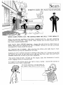
WHEN
SEARS
PEOPLE
SAY,
"WE
SERVICE
WHAT
WE
SELL."
THEY
MEAN
IT,
When you get your appliance
from Sears, Roebuck
and Con, you get something
• nobody
else can give you - Sears service. Many families who've
been around hate to
buy even a toaster anywhere else.
Every month,
about 400,000
Americans
change jobs and move to other
states. Many more are transferred
by their compames,
Families on the way
be prepared for moves around the cotJntry_
One important way to prepare_° take
around the country_ Buy your appliances
a tip from the military
from Sears.
who
really
towns or
up should
have
to move
Suppose you live in Denver and you're moving to Bay Shore, NX, As soon as you and
the moving van arrive, all you have to do is call your Bay Shore Sears store and they'll
schedule a technician to hook up your Sears appliances.
"We service what we sell." To back up this
trucks, logging millions of miles each yean
Is it worth
it? Ask anyone who's ever
around the corner. Sears is nationwide.
For handy
your nearest
had to
reference,
use
Sears Service
slogan,
Sears has thousands
move a family
this space for
Phone Nurnber_
- around
the
of service
country
or
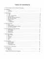
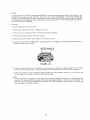
TABLE
A÷
Water,
Detergent,
and
the
Automatic
OF CONTENTS
Dishwasher
................................................................................................
3
B_ Installation
...........................................................................................................................................................................................................
7
,
Portable ..........................................................................................................................................................................................
7
7
2, Undercounter ..................................................................................................................................................................................
C_
Wash
I_
2,
3.
4.
5,
6.
7.
8.
System ...........................................................................................................................................................................................
16
2 Level .............................................................................................................................................................................................
16
3 Level .........................................................................................................................................
,......................................................
19
2 Level - Compact Modeis .............................................................................................................................................................
20
Water Inlet Valve ............................................................................................................................................................................
21
Side Water Inlet/Steam Trap/Venting ....................................................................................................................................
26
Motor and Pump Assembly ..........................................................................................................................................................
27
Hos_s and Couplers .......................................................................................................................................................
_:.................. 42
Dispensers...................................................................................................................................................................
:........................
45
a. ' Detergent ..................................................................................................................................................................................
:,.................. 45
b.
D,
Er
Fo
Wetting Agent .........................................................
_,:................................................................................................................
47
Electrical
Controls ..................................................................................................................................................................................
49
1. Timers ...............................................................................................................................................................................................
49
2. Selector
Switches................................................................................
50
34 Thermostats and Temperature Indicators .........................................................................................................................
51
4. Door,and FloatSwitches
..........................................................................
59
Wiring
i
2.
3
4.
Diagrams
and Ester line Charts .........................................................................................................................................
61
Wiring Diagrams ..............................................................................................................................................................................
61
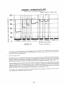
Ester line Charts ..............................................................................................................................................................................
R2
Voltage Checks .......................................................................................................................
..........................................................
66
Continuity
Check.................................................................................
67
Mechanical
!,
2_
3.
&
5,,
6.
System
..................................................................................................................................................................................
68
Door Assemblies ..............................................................................................................................................................................
68
Racks .........................................................................................
71
Tub Gaskets ....................................................................................................................................................................................
72
Cord Reel ........................................................................................................................................................................................
75
Casters .............................................................................................................................................................................................
76
Tubs .................................................................................................................................................................................................
77
G. Drying System .........................................................................................................................................................................................
78
1_ Convection Method ..........................................................................................................................................................................
78
2, Forced Air Method ..........................................................................................................................................................................
79
3, Heating Elements ............................................................................................................................................................................
8]
a. Power Miser Option .................................................................................................................................................................
82
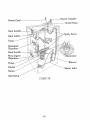
H,
Pictorial
View
of Dishwasher
...........................................................................................................................................................
84
Troubleshooting
......................................................................................................................................................................................
85
1, General .............................................................................................................................................................................................
85
2,, Water Leaks....................................................................................................................................................................................
91
MISCELLANEOUS
SERVICE PART NUMBERS ......................................................................................................................
92
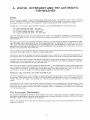
INTRODUCTION
This service manual is designed to provide you with a basic knowledge of the operation
of your Kenmore Dishwasher.
It was not designed to cover a specific model, but covers, in detail, the repa!r of most
components used on any model. The production of a service manual for each individual
model is not practical because of the excessive duplication that would resutL
Thorough study of this manual will provide a good working knowledge of the compo,nents that may be used within a Kenmore Dishwasher,. Application of this knowledge
to a specific dishwasher should make repair relatively simple.
Included
in this manual
are installation
instructions
and service
procedures.
The importance of proper installation of any appliance cannot be overstressed. Our
experience indicates that incorrect installation is a major cause of unsatisfactory
product performance.
CAUTION
- PLEASE
NOTE
Sears, Roebuck and Co. assumes no responsibility for any repairs made on our products
by anyone other than our own Service Technicians,
Replacement of the dishwasher tub should be performed only by a qualified technician°
It is recommended that you contact your nearest Service Department for this service.
As a safety precaution, ALWAYS disconnect electrical
before attempting to make any repairs_
power from the dishwasher
A. WATER,
DETERGENT AND
DISHWASHER
THE AUTOMATIC
Water
Water is a primary ingredient in determining automatic dishwashing result5
The minerafs in water, when in sufficient
quantity, wilt cause spotting, filming and the possible discoloration
of some metals. The minerals which account tot
the greatest difficulty are calcium and magnesium
These minerals delermine the hardness ol the water
Theaefin[tibn
0 to
4 to
8 to
over
of hard _ate_: varies s6h_ewP;at
However[
m6s{-a_Jthor[fies
a'gree G4th the following
scaie
"
4 grains hardness per gatlon - soft water
8 grains hardness per gallon - medium water
12 grains hardness per gallon - hard water
12 grains hardness per gallon - very hard water
Automatic
dishwashing
results are v_stb/y affected when calcium and magnesium are present in a concentration
ot
eight grains per gallon ol more As their concentration
increases, the problems of spotting and filming can increase
proportionately
When spotting and filming are caused by hard water conditions, they wilt normally be evident on glassware and tableware (silverware! within a short period of time Over a longer period of time, hard water film can build up on the racl.:s,
walls, spray mechanism and heating element of the dishwasher itself The development
of hard wa'ter film on the
dishwasher may cause additional problems and reduce the efficiency of the dishw_tsher due to the build-up of the time
deposits on the pump area, drain hoses, etc
If water supplied to the dishwasher is less than !0 grains hard, spotting
the amount of detergent used. in a properly functioning
dishwasher
and filming
can be controlled
satisfactorily
by
When correct amounts of detergent are used for the availing water conditions,
the water softening ingredients wilt
also dissolve calcium and magnesium which have deposited on dishware surfaces in preceding dishwashing
cycles
In medium and hard water conditions,
the amount of detergent used should be increased We recommend
fdhng the
detergent cups under these conditions
In some very hard water conditions,
it may also be advisable to place additional detergent in the dishwasher for the main wash cycle
When the total hardness of
unit to remove the catcium
washing results Also keep
_nq correctly or it may not
REMOVAL
AND
the water exceeds 12 grains per gallon, it may be advisable to install a water conditioning
and magnesium from the water, in order to insure continuous excellent automatic dishin mind that when a customer already has a water softener that it may not be functionbe able to handle the capacity needed for the size of the household
CONTROL
OF HARD
WATER
FILM
A 5% or 6% acidic solution, such as vinegar, will remove hard water film and may be used lo determine its presence
on glassware Place a small amount of vinegar in a bowl and allow filmed glassware to soak in the vinegar for 3 to 10
minutes
Remove from vinegar, rinse and blot dry tf the film present was due to hard water, it will have been removed
The following "home"
method may be used to remove hard water film from glassware and the dishwasher:
Allow
dishwasher to fill for the main wash cycle; place two cups vinegar in the water and allow machine 1o complete the
entire cycle Do not place metalware, plasricvvare, silverware, cutlery, or detergent m dJsh_c'asher when performing
[h_ fffm _tnpping prodes_
The Automatic
Dishwasher
The automatic dishwasher is blamed for many problems over which it exercises no control
A properly funclioning
dishwasher, properly loaded, using the recommended amount of a good dishwasl_er detergent and having the speci*
fled water charge will do an excellent job of cleaning
Some of the problems
washer are as follows:
that do arise and are caused by conditions
other than functional
characleristics
of the dish*
Sudsing- You
are familiar with the mountains of suds that result from using the wrong detergent
in an automatic
washer
A similar problem in an automatic dishwasher
can be caused by using improper detergents,
using solid
jet dry. a leaking wetting agent dispenser or excessively
tow or high water temperature
A complaint
of poor
cleaning of dishware may accompany this problem
Sudsing leaks in a dishwasher will usually occur at the door
gasket or the blower housing
On hard to find leaks, suspect sudsing and check the following:
Use a fresh detergent made especcal/y for automatic d_shwashing.
Such detergents are labeled on each container
for automatic or electric dishwashing
When in doubt, consult the Owner's Manual; i1 contains the recommended
detergents,
or use recognizable major brands
Water temperature
recommended
on most detergent
packages is 140° if water temperature
is extremely low
(120 °) or extremely high (180°}, then sudsing will surely occur For best results from detergent and wetting agent
liquid, water temperature should be between t40 ° - 150°F Solid jet dry should be avoided except if you should
choose to place the jet dry in dishwasher for the final rinse only
Hand pre-washing
of dishware with .Joy or other such dishwashing
liquids or soaps prior 1o loading can cause excessive sudsing since this liquid may not be thoroughly
rinsed away and, ,when agitated in the dishwasher,
can
cause sudsing
A malfunctioning
of the wetting agent dispenser mechanism which would allow excessive amounts
dq,' to be released in the rinse or wash may also cause excessive sudsing
Each injection of wetting
should be approximately
8cc
Etching
actually
of liquid jet
agent liquid
- Etching of glassware is the result of soft glass and an alkaline compound.
The surface of the glass has
been destroyed and no amount of rubbing can restore the glassware to its original state
A quick check for etching can be made by scratching the surface of the glass with a pin
ing" (white film) can be removed, the condition is an undesirable film but not etching
If the "stain"
or "spott-
Permanent etching of glassware can in no way be caused by the operation of the dishwasher The dishwasher can
only be a contributor to the problem if it is not properly circulating the water charge
Make sure the dishwasher is operating normally and there is an adequate supply (volume)
fill each time Check to be certain the water is circulating
and the detergent is fresh
There are several factors which
cause or contribute
1
Extremely
hot water
2
Excessive
use of detergent
3
The water ts soft
4
Composition
[mineral
5
Composition
of the glasses themselves
to permanent
(0 to 4 grains hard, either naturally
makeup]
control
staining
for water condition
or thru a softener)
of water
Softened water is more detrimental than naturally soft water
moved There may be a definite need for a softener
We can elfectively
(etching)
of water to insure a good
only two of the above
factors;
wa[er
We do not imply that the water softener be re,temperature
and amount
of detergent.
We recommend when etching is encountered
in the amount of detergent used, consistent
may be adequate
that water temperature
with good dishvvashing
be set no higher than !40°; and a reduction
results
One tablespoon per detergent cup
This may not completely
but it wilt help 1o slow
down
eliminate
etching,
the process
of etching
of glassware
3
Dishwashmg
Problems andAnswers
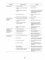
PROBLEM
DishesNotClean
POSSIBLE
CAUSE
Water temperature
to 66°C,)
& SOLUTION
is too low
It should be from
t40°Fo to t50°F
Not enough water in the dishwasher
Using old, lumpy detergent
Improper loading
Items may be placed in the wrong position
a slender handle may have prevented spray arm turning
Spotting
A knife or
Caused by minera! deposits from ha(d or soft water left by evaporation
Use a wetting agent such as Jet Dry Store dishwasher
detergent
in
a c0ol, dry place
Filming
Water is too hard Use more detergent
tf hardness is greater than ]2
grains, you may need to install a water softener
Usually hard water
film can be removed by soaking a glass in a half and half solution of
vinegar and water, ° If this proves effective,
load the filmed glasses
and dishes into the dishwasher
Operate on LIGHT WASH cycle Stop
the machine after it has filled for the wash phase of the cycle and pour
in two cups of vinegar Close the door and let the machine complete
the cycle
°Some commercial
your area
Etching
...........
Silverware
Stained
or Pitted
Bronze Tarnish on Silverware
Black Marks on Dinnerware
Aluminum
Brown
(60°C
Discoloration
Stains (Rust) on Dishes or Tub
Dishes Not Dry
products
such as Glass Magic
may be avaifable
Etching appears as a film and is impossible to remove It can be retarded
by using smaller amounts of detergent
Thorough rinsing is important;
so load your dishwasher
properly.
Do not overload
it Dishwasher
water temperature
should be at 140°F. (60°C),
Can be caused by direct contact with detergent or prolonged
contact
with acid or salty foods Do not let detergent drop on silverwai'e
Rinse
tableware promptly if it has been exposed to staining foods.
Silverplate has worn off, exposing base metal, Silver polish
tarnish but replating is necessary for permanent solution
can remove
Can be caused by metal objects rubbing the plate Remove the marks by
soaking the plate in a mild Meach solution
After this, wash the ptate
in a normal dishwasher cycle
Minerals
in
combination
your
water
supply
with some detergents
Too much
installed
iron in your water
The water
washer
is too cool
Improper
loading
It should
and high water
temperature
can darken aluminum
You may need iron removal
be at least
Load dishes so the water
140°F
(60°C)
Use of wetting agent for those dishwashers
pensers helps water to sheet off faster
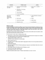
Dishwasher Odor
at the dish-
can run off
equipped
with automatic
Improper loading
Load glassware and dishes between
they are stable and cannot bump each other
Soiled dishes held too long in dishwasher
dishes that will be washed later
in
equipment
On machines without forced air drying, try opening the door slightly
the beginning
of the dry cycle Unload after about an hour
Select "Hot Dry"
Dishes Chipping
in
the supports
at
dis-
so
Use RINSE 8 HOLD cycle for
Noise
Some hard object (bottle cap, measuring spoons,
into the bottom of the tub Clean the pump
etc ) may have fallen
Water in Tub Bottom
A small amount
cycle
of the tub after each
of water will remain in the boltom
CLEANING
MINERAL
DEPOSITS
FROMPORCELAIN
SURFACES
Thefollowingprocedure
issafeif theinstructions
arecarefullyfollowed
Manycomplaints
of porcelain
delerioration
havebeentracedtoa surface
discoloration
duetothepresence
ofiron,
manganese
or calciuminthewa;ersupplyInareashavinga highmineralcontentin thewater,particularly
iron,
discoloration
orstainscanusuallyberemoved
bythefollowingmethod:
t UsewatersoftenerResinCleanerThiscompound
isavailable
fromSearsPlumbing
and
2
Pour 8 ounces of the compound
3
Fill the 2rid wash detergent
4
Select a normal cycle - must have 2 washes and 4 rinses
5
Allow
6
DO NOT place dinnerware
the dishwasher
into the bottom
cup with dishwasher
to complete
detergent
and close the cup
It is not necessary
in the dishwasher
during
to complete
the cleaning
operation,
CA U T/ON:
Because of the obnoxious odor of the cleaner in solution - Do Not open the dishwasher
door until the completion
of the last rinse°
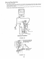
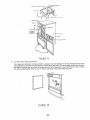
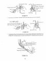
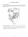
How To Remove
Access
Department
of the tub
all washes and rinses
or silverware
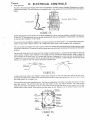
Heating
The
Panel
Attach
Screws
Access
Panel
/
Bottom
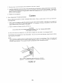
Loosen the two bottom attach screws in the access
pane_
Open dishwasher door,
Remove the two top attach screws
Close door
Access panel can now be removed by
puIling straight off
the dry cycle
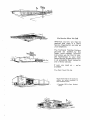
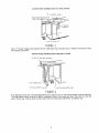
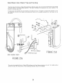
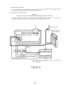
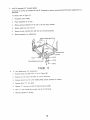
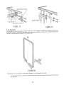
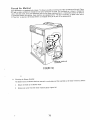
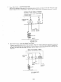
B. INSTALLATION
Portable
Dishwasher
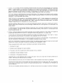
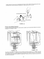
Hot Water Connections - Portable Dishwasher
I.
Attach the AERATOR ADAPTOR furnished with the dishwasherto the sink faucet.
2.
Check the power outlet.
A.
Will it take the three-prong plug on the power cord?
B. Is the outlet grounded?
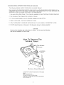
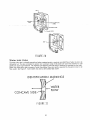
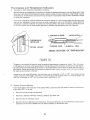
CHECKING POWER OUTLET
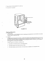
The dishwasher
willoperateon regular
housecurrent,
Do notuseanyotherappliance
on thesame circuit,
Use a circuit
withat Jeasta 15 Ampere,butnotmore thana 20 Ampere fuse.
The dishwasher
power cordisa threeprongtypeand
must be pluggedintoa threeholegroundedoutlet°
The dishwasherMUST BE GROUNDED forsafeoperation,,
Do not,
underanycircumstances,
removethepower supplycordgroundprong°
Under
Counter
Dishwasher
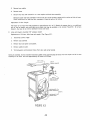
Drain,
Water,
and
Electric
Supply
I
I
I
!
I
I
16
FIGURE
!
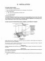
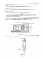
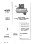
Copper tubing must have a minimum I,D. of 3/8 inch. Sears has a waterline kit which includes all the fittings and
instructions you need for most installations.
How much water volume is needed? A minimum flow of 8 quarts of hot water is required in 60 seconds - Check this
at your kitchen faucet tap with the aerator removed.
Provide a separate
20 Amps.
circuit
with
IMPORTANT:
fuse or circuit breaker
This Appliance
Must Be Permanently
Local Codes and Ordinances°
rated
IMPORTANT:
Grounded
In Accordance
for at least
With
15 Amps
The National
but
not
Electrical
more
than
Code and
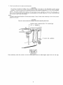
When installing the dishwasher:
I.
Connect (in junction box) incoming black lead to dishwasher black lead; and incomingwhite lead to dishwasher white
lead.
2
Attach
grounding
wire to green grounding
screw
CAUTION:
The joining of aluminum building wire to stranded copper wire leads on the dishwasher
involves special
problems
It should be done only by qualified personnel using material recognized by U/L (or CSA) as suitable
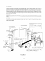
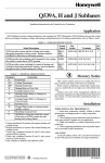
DRAIN.
Improper!y installed drain hoses can kink and result in poor washability or failure of the dishwasher to
drain Do not use the drain hose supplied with the dishwasher for the water supply line It is not a reinforced hose
and wil! burst under water line pressure
NOTE,"
A properly operating dzshwasher
pletion .of [he cycle. .........
will have approxtma_e/y
.2 cups of clean water rematmng
CA UTION:
Be sure to remove plug from disposer inlet before attaching
DRAIN
OR "y"
HOSE CONNECTED
BRANCH
drain hose,
TO DISPOSER
2"HOLE
SINK
in [he [ub at the com-
OR LARGER
X,,T LEFT
FIGURE2
After
positioning
under
the counter,
the front
iMPORTANT:
leveling legs should
be raised slightly
higher
than
the rear legs.
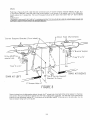
DRAIN HOSECONNECTIONTO SINK DRAIN
/2 ! O COPPER
DRAIN HOSE MUST
THAN DIS
TUBING
BE _tGHER
3RANCH
TAILPIECE
S{NF,
AT
RIGHT
FIGURE3
Sears "Y" Branch Tailpiece
and complete instructions,
and Connector
DRAIN
Kit No, 729b makes this connection
HOSE
CONNECTION
AIR GAP KIT AVAILABLE
2"{OR
LARGER)
THROUGH
easy, It includes a!l necessary fittings
FLOOR
AT SEARS
HOLE
\
\
LEFTNAND
SUPPORT
RIGHTHAND
SUPPORT
ANGLE
FIGURE4
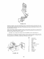
If the dishwasher drain hose is routed through the floor to a separate trap, the trap must be vented to prevent siphoning,
To provide proper venting, install an Air Gap Kit (available at Sears) in the countertop, Route drain hose up to the inlet
side of the Air Gap, Continue drain line from outlet side of Air Gap down through floor to separate trap,
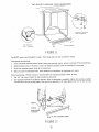
Models
Equipped
With
Installation
Module
PLANNING
Determine the rouling for the water supply, eleclrical
sin!tarpon so that space conflicts do not occur
Important
- Do no1 [oute
CUTTING
ACCESS
ptumbing
or wiring
wiring
and drain
in front of the motor
line before
or dishwasher
proceeding
support
with
the actual
in-
channels
HOLES
Access holes in the cabinet sides or floor should be located within the zones shown in Figure 5 The hole for lhe
drain lineshould be 2" diameter minimum
The two holes for the electrical and plumbing lines should be 1" d,ameter
minimum
Keep the electricaland
plumbing lines separated
fl!:.....
FIGURE5
INLET VALVE
,JUNCTION
BOX ASSEMBLY
Locale the valve and junction box assembly as shown in Figure 6 using the template supplied Attach the assembly 1o
the floor through 1he two holes near the junction box (If unable to atlach the assembly to the floor, locale according
to the template, connect water and electrical as described below, then connect the assembly to the side base ol the
machine with the bracket provided after the machine is in the cabinet )
WARNING:
IT IS ESSENTIAL THAT THE ASSEMBLY
BE LOCATED CORRECTLY
CLEARANCES AND PREVENT DAMAGE DURING DISHWASHER
INSTALLATION
t0
TO MAINTAIN
ELECTRICAL
ELECTRICAL
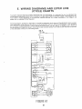
All wiring must be in accordance with electrical codes The dishwasher operates on !15 volt, 60 cycle power
vide a separate circuit with a fuse or circuit breaker rated for at least 15 amps bul not more than 20 amps
Pro-
GROUND1NGINSTRUCTIONS
This appliance must be connected
to a grounded metal, permanent,
wiring system; or an equipment
grounding
conductor must be run with the circui_ conductors and connected
to the equipment-grounding
terminal
A green
ground screw terminal is provided in The junction box Connecting
the circuit conductor
ground, along with the
molded receptacfe green pigtail, automatically
grounds 1he dishwasher
install the wiring, routing it within the zones
lhe circuit black 1o the machine black, and
aluminum,
a UL or CSA listed antioxidant
Connect the circuit conductor ground wire
box cover
shown in Figure 5 Do not run i! across in front of the motor
Connect
circuil white to the machine white, using wire nuts If house wi_ing is
compound
must be used with listed aluminum-to-copper
connectors
under the green ground screw Refer to Figure 6 Replace the junction
CIRCUIT
CONDUCTOR
GROUND
¢7IRING
GREEN
SCREW
\
FIGURE6
11
GROUND
WIRE
WA] ER SUPPLY
Plumbing must comply with local codes It is recommended
that a shul-off valve be installed in the line from the
supply to the dishwasher
The water supply must be able lo supply a minimum of 9 quarts in one minute Route the
Ime, as shown in Figure 7 (Refer to Figure 5 for permissible routing areas)
Do not run it across in front of the motor
Piping must not be kinked The connection to the valve is made with a 3/8" male pipe thread right angle adapter
Assemble the adapter to the valve, using pipe compound or teflon tape, with a wrench on the adapler and a wrench
over the metal bracket enclosing the fitting on the valve If solder connections
are used. use care to see that valve
is not overhea!ed
CAUTION!
Qverheating witl da0qage the valve Clean all ioreign matedal from the pipe and threads
before maldng final connections
IMPORTANT:
TURN ON THE WATER
LEAKS.
SUPPLY
AND CHECK ALL PLUMBING
AIqD DISHWASHER
CONNECTIONS
FOR WATER
WARNING!
Do not have line pressure Io the water valve in freezing temperatures
during construction,
remodeling,
elc Do not
use the drain hose supplied with the dishwasher for the water supply line It is not a reinforced hose and will burst
under water line pressure
CAUTION
To prevent damage to valve,apply
wrench to hex on valvemetal bracket
I
and hold securely
rigflt angle adapter,,
while
installing
SUPPLY
I
I
_REEN
SCREW
ALTERNATE
ENTRY
DDT_ED
SHUT
OFF
VA LV E
HOT
SHOWN
LINE
GROUND"
WATER
BY
\
HOT
LINE
WATE
MOLDED
/
FIGURE7
12
RIGHT
ANGLE
MALE
PIPE
ADAPTER
THREAD
REO
EPTACL
-3/8
DRAIN
Referring to Figures 8 and 9. install the drain connection
parts (Y branch tail-piece, disposer adapter, air gap, etc )
in the location selected
Instali the drain hose corner support in the corner of the cabinet next to the dishwasher
directly above the 2" access hole The top of the support should be 30" above the kitchen floor 124-' above cabinet
floor)
IMPORTANT:
THE DRA!N LOOP MUST BE FIXED ATA lvl!N,!MUM HEIGHT,,QF,,,32 INCHES BY USE OF A SUITABLE CLAMP OR
SUPPORT._ONE -IYPE OF WHICH IS SHOWN BELOW.
Drain
Corner
Support
Bracket
Hose
(Furnished)
(Furnished
"'Branch
Entry
above
\
MUST be
trap
Trap
Tailpie(:
P or
S
_1_ t
\
Trap
P or S
SINK AT RIGHT
3O"Top of Corner Support
Bracket
To Floor
SINK AT LEFT
2
Access
Hole--
FIGURE8
Route the hose from the dishwasher cabinet through 1he 2" access hole, then behind the corner support to the drain
and connect
Be sure all bends are smooth and the hose is adequately supported
The free end of the hose should
extend into the dishwasher cabinet 20" if the hole is on the left side, and32" if the hole is on the right side Cut the
hose to length, being sure cut is square
13
Air
1
Gap
Kit
codes
2
{Available
Required
when
Required
Irap
by
at Sears}
some
local
plumbing
10 a disposer
connecting
when
benea'lh
connecting
7o
a separate
1he floor
Corner Support Bracket (Furnished)
Trap
P or
S
To Separate
Trap
Beneath
Floor
SINK
\
AI LEFT
SINK
AT RIGHT
FIGURE9
HOW
TO POSITION,
ALIGN,
AND
LEVEL,
YOUR
DISHWASHER
FIGUREIO
Move your dishwasher,
as necessary, to:
Align the front of the dishwasher,
2.
as close as possible, with the front of the cabinets,
Make the space between the dishwasher and the adjoining cabinets the same on each side and the same width top
to bottom, Use the stubby screwdriver or 7/=32" socket to adjust the teveling screws, They must be set firmly against
Lhe floor,
14
TWO
WAYS
TO ANCHOR
YOUR
DISHWASHER
F $oc_r anchori_g
with
_'
lag
screw_
_
Toe
plate
assembtv
FIGURE11
You MUST
anchor your dishwasher to keep it from
Countertop
tilting
when the door is opened or closed.
Anchoring:
1.
If the countertop
mounting
bracket flange is }onger than you need, mark it, remove it, and saw off the unneeded part.
2,
Adjust
3
Screw the mounting bracket firmlyto the counter[op,
4
Open and dose the dishwasherdoor° There should be no interference
or scratchingas itmoves,
leveling screws, if necessary, so that
Floor Anchoring:
the mounting
brackets touch the underside of countertop
Difficult procedure. Use only where the countertop bracket cannot be used.
1
Use 1/4"
lag screws through the holes provided as illustrated
2.
Use expansion fasteners if the floor is concrete After the anchoring is completed, replace the toe plate assembly
You will notice that the vertical height of the toe plate is adjustable to fit neatly against your floor or floor covering
INCREASE
\
DECREASE
_"_-.,-_OE
PLATEADJUS]MENTSCREWS
FIGURE12
15
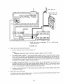
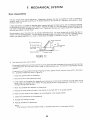
C. WJASH
SYSTEM
FIGUREI3
Two
Level
Wash
Feature
A separate spray tube or rotating spray arm assures excellent washability
in the upper rack, and another rotating
spray arm thoroughly washes all dishes in the lower rack This arrangement
permits complete flexibility of ioading
without concern of blocking the water pattern to el;her rack See Figure t3
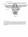
Water Charge (See Figure 14)
Water
enters the dishwasher
through
the solenoid
operated
water
inlet valve
The valve is energized through the timer Water will enter the machine 1or approximately
one minute
(All dishwashers are time filled ) Some models fill for 90 seconds
Also some models have 45 second water charges built
into water miser and normal wash cycles Refer to tech sheet in console
NOTE:
The float switch controls the amount of water entering the dishwasher
The fill is also time controlled
timer fails to advance or the water pressure is extremely high, the float switch will open the circuit to the
inlet valve thus preventing a flood If the float sticks or does not cut power to the valve, the timer acts as a
_o turn power off after the allotted fill time The float and timer switch will not protect against a mechanical
of the valve
If the
water
safety
failure
To satisfactorily
clean dishes, the 24" dishwasher must have a water charge of 8 to 11 quarts The !8" models
require 6 5 to 8 quarts if poor washability
is experienced,
be certain to check for the correct water charge
16
NORMAL
FLOAT
SWITCH
FIGURE14
2
Testing
Water Charge Level
To check for proper water level, pour the minimum charge ol_8 quarts of water into the tub and make a reference
mark with a grease pencil or crayon at the edge of the waterline
Then pour in an additional 1 Y_,quarts of water
to make the maximum charge, and make another reference line at the edge of the water line, Set the timer to a
portion of the operating cycle for "drain" and allow the drain pump to pump out the water Allow the time to advance into a )_;fill" period of the operating cycie and allow the normal amount of water to fill the tub After the
water inlet valge has shut off, compare the edge of the water line with the reference marks made above The water
charge must be belween the two lines Remove the marks after completing
this test The water level should cover
tile heating element
17
t t
ttttt
FIGURE15
.
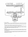
Spray Arm Assembly
The spray arm is mounted to the upper pump housing_Water from the sump is pumped through the upper pump
housing where it is directed to the spray arm..The water is discharged from ports in the spray arm as shown in Figure
t5..
The velocityof the water discharged from the ports and the angle of the port opening causesthe spray arm to rotate.
The rotation of the spray arm assures the distribution of water to all corners of the tub,
A stuck or split spray arm can cause ieaks or poor washability. On complaints of this type, inspect the spray arm
closely for a possible split seam. Be sure the spray arm turns freely on the pump housing. If binding is encountered,
it wilt be necessary to replace the pump housing or spray arm, or both°
_
5pray Tube
The spray tube or middle spray arm directs water to the upper rack to assure complete washing and rinsing of all
plates and glassware. Water is pumped from the sump, by the lower impeller, through a hose connected to the spray
tube or middle spray arm,
On models having the upper rolo rack, be certain the racks turns freely. Unsatisfactory washing of the items in the
upper rack will result if the rack binds, is prevented from rotating by a tall item in the lower rack, or water is not
being discharged from the spray tube..
18
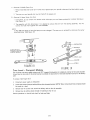
Periodic cleaning of the spray tube is recommended One method is shown is Figure 16. The loosened particles may
be flushed from the tube by operating the dishwasher in a wash cycle with the cap removed,
PUSHLODGED
PARTICLES
UPPERSPRAYTUBE
SCREW THREADS
FIGURE16
Three
Level
Wash
System
The upper or third level wash system used in certain
the upper rack° See Figure ]7 A & B.
SPRAY
Y
models is intended
to give increased wash efficiency
for articles in
'iUBE
ADAPIDR
FIGURE17A
FIGURE17B
The water for the system in 17A isbled off from the middle wash system by means of a "Y" adapter in the main
supply tube and a branching "L" shaped supply tube from thatpointto the lop centerof the tub In 17B the top spray
arm is supptied directly from 1he pump by means of an external supply tube The tower in the center of the lower spray
arm telescopes upward washing the underside of the upper rack To remove the tower unscrew the lower section of
the tower counterclockwise
19
A
Removal of Mtddle
Spray Arm
1 Remove stainless steeI cotter
arm
2
The spray arm and spindle
Removal
of Upper Spray Arm
remove
pin in lower end of plastic spray arm spindle underneath
the black plastic supply
can now be lifted off the supply arm
Only
1
From below, in tub,
(See Figure 18 )
two screws
which
hold spray arm and bearing
2
The assembly will then drop loose If il is desired to remove
screws the1 hold them together are nowraccessibte
NOTE
In Mid- 1980 [he design of the third ,spray arm was changed
moun_ing screw [See Figure 79]
the arm from
assembly
to plastic
the bearing
The spray arm is removed
distributor
assembly,
by removing
the 1we
the center
BEARING
ASSEMBLY
&$
ARM
;HER
(_
FIGURE18
SCREW
FIGURE19
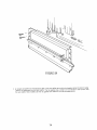
Two
Level
- Compact
Models
The top spray arm water supply system on all 18" (compact) dishwashers is completely external of the wash chamber,
A hose from the back side of the pump housing runs behind the back center of the wash chamber (tub) up to the delivery
tube
To remove: (See Figure 20)
1,
Disconnect power supply to dishwasher,
2
Loosenand remove clamp attaching delivery hoseto pump housing /VOTE: Water remaining in hose and pump should
be caught in a bowl
3
Remove four (4) screws that attach the delivery tube to the tub assembly,
4
Remove hose by pulling slowly through the opening in rear of tub.,
Reverse procedure to reinstalf and check for leaks and kinks,
20
DELIVER
TUBE
HOSE
STEP 2
STEP
FIGURE20
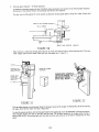
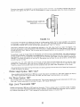
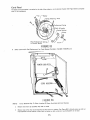
Water
Inlet
Valve
The water inlet valve is solenoid operated and when energized permits a constant controlled flow of water to enter the
dishwasher tub, The valve is designed to operate over a pressure range of 20 pounds per square inch minimum to 120
pounds per square inch maximum, The frequency and length of Lime the valve is operating is controlled by the timer,
Water inlet valves differ only in amount of water they deliver (flow rate) which is governed by the aperture size in the
flow washer See Figure 21, Some models may have a three orifice flow washer
IDENTIFICATION
MARKINGS
"_WATER
CONCAVE
'
__1 '_-" FLOW
SIDE
FIGURE21
21
A
Operation
Figure 22 shows a cross section of the water inlet valve in its closed position and Figure 23 shows it in its open
position The water pressure at B and C has equalized because the bleed hole opening permits water to flow from
B to C Pressure at A is atmospheric
(Figure 2.2)
The valve remains closed because the higher water line pressure at C is greater than the atmospheric pressure at
A. When the solenoid coil is energized by the timer, the plunger is withdrawn from the diaphragm opening Water
in compartment
C wilt then escape through the diaphragm opening causing the pressure in the compartment
to fall
to almost atmoshpheric pressure, The higher water line pressure at B forces the diaphragm away from its seat,
opening the valve Water then flows through the screen under the diaphragm and out the valve.
PLUNGER
HOLE
LINE WATER PRESSURE
WASHER
ATMOSPHERIC PRESSURE£
B
FIGURE22
CLOSED
POSITION
PLUNGER
DIAPHRAGM
B
-FLOW
WASHER
FIGURE23
OPEN POSI'[ION
When the solenoid releasesthe plunger, the hole in the center of the diaphragm is sealed. Water then flows through
the bleed hold in the diaphragm until the pressure in compartment C rises to water line pressure. Since the area of
the diaphragm at water line pressure in compartment Cis greater than the area at water fine pressure in compartment
B, the diaphragm is forced closed. The pressure at A is always lower than full line pressure because water passing
through the valve is escaping to the open air.
22
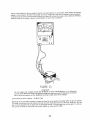
Testing
To test operation of water inlet valve, place the leads of a volt meter across the termina{s of the solenoid in any
fill phase of the operating cycle where the water inlet valve should be energized
If the meter indicates tine
voltage, water should flow into the tub If water does not flow into the tub, either the water inlet valve is defective
or the water supply is inadequate
Make certain the hot water faucet is fully on If the water supply is not at fault,
the water inlet valve is defective
C
Sen/zcing
To Clean Operating
Parts of the Vaive:
!
Remove
valve bracket from
2
Remove
4 screws
3
Remove
the plunger
4
Check the parts for defects,
5
Check 1o make sure the tiny bleed hoies in the diaphragm
necessary, using a pin or needte
holding
tub or installation
solenoid,
housing,
module
valve body and bracket
spring
together
and plunger
dirt particles
or for formation
of lime
are not clogged
See Figure 24 Clean bleed holes, if
BLEED HOLES
FIGURE24
6 Clean the screen mesh of any rust particles
the iob by blowing
screen clear
Use running water to remove any large particles; then, complete
The screen mesh must be absolutely clean and free of any damage
7 Check flow washer for wear or damage
the markings
on the washer
When reinstalling the flow
face the incoming flow of "water.
washer,
NOTE
The Timer Controls the Operazton of the Water Inlet Valve and therefore,
machine
The Valve should be energzzed for 45 to .90 ._econds depending
float switch will .shut the water off at the proper level The Timer controls
acts as a safety on full water charges
23
position
i1 in the valve so that
the amount of water emenng the
on model and cycle selected
The
the wa[er charge on short fills and
Water Inlet Valve Kit
Undercounler 808668
Portable 808667
KI'[S INCLUDE:
t water vane
! metal washer
4 flow washers
This ki_ is used for several applications
dishwasher
t
1
2
t
plastic retainer
screen
terminal insulators
sealer washer (undercounter
only)
Use the flew washer in this kit which wi_! provide
the correct
flow rate for your
Install parts in the order illustrated
PORTABLE
UNDERCOUNTER
METAL
WASHER"
FLOW
METAL
WASHER--'_
PLASTIC
FLOW
_
WASHE
]
PLASTIC
RETAINER
F:RETAIN
SCREEN
E __
CURVED
(__
SIDE
SCREEN
SEALER
WASHER
1
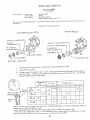
Remove plug from valve, discard
Remove any foreign particles from valve
2.
install flat metal washer,
3,
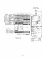
Choose correct flow washer from the chart. =Fhereare identification
markings Qn the fiat side of
the flow washer° Install the flow washer with identification
markings facing you
Curved side
should be against the ftat metal washer.
DISHWASHER
WIDTH
24';
METAL
WASHER
IDENTIFICATION
4E
2,0,2,5
_af/min
5E
6F
1,6 Z 10%
'"
-60sec,(gO see
---'-----1 45 sec_
VALVE
Whiiei _'oeo"Yellow
E
Lt, Blue
X
Biue
IX X
X
X
X
Red
....
F---
X
1 75_-lo%
MARKING_
IB"
ORIGINAL
FILL TIME
b<
X
X
NOTE:
Do not rely on original valve color only
make sure the correct flow washer is used.
b<
Compare dishwasher fill time and dishwasher
width to
*Some models with 90 sec. fill time use an abbreviated water fill (45 sec) on certain cycles.
If the valve on the dishwasher is pink, it is a replacement valve, Use the same flow washer as in the valve
Refer to dishwasher width vs, fill time to make sure it is the correct flow washer
24
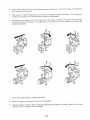
4,
Install plastic retainer into valve with center protrusion
cut into the body of the valve
facing you, Push untii it snaps into the groove
Press screen into valve, being careful not to crush or change the shape of the screen,, This is important
to keep dirt particles out of the valve tha't will cause it to malfunction,
6
The solenoid and bracket on this valve may have to be rotated in relation to the vatve body to match
the original valve as illustrated,
You need only to take three of the four screws out to rotate the
solenoid and bracket
7., Install the sealing washer on undercounter
valves,
8,
Mount the valve to the bracket or frame of the dishwasher_
9.
Recheck selection of flow washer by operating dishwasher through
correct for the flow washer you have selected,
25
the fill phase° Make sure fill time is
Side
Water
Inlet,
Steam
Trap
and
Venting
The side water inlet shown in Figure 25A provides an effective steam trap at all times and eliminates vapor escape
during any phase of the dishwashing operation
The vapor is blocked from escaping by the water trapped in the
bottom of the side water inlet
The side water inlet assembly fits into a bracket on the side of the tub The plastic nut secures the assembly
tub Removal of the nul from inside the tub allows the inlet unit to be easily removed from the botlom
dishwasher
to the
of the
PLASTICNUT I
-,..
WA1ERiNLETASSEMBLY
TOWATERINLETVALVE
SIDE WATER
FIGURE25B
INLET
FIGURE
25A
The water inlet assembly shown in Figure 25B combines the fill and blower opening in the lub
forced air drying, the lower portion of the housing and blower motor is not installed
26
On models
without
4
_"_--_-- VENT
*---OUTER
GRILLE
DOOR
PANEL
JI,
INNER
DOOR--'_
EXIT
FLOW
OF MOIST
DURING
DRY CYCLE
VENT
AIR
'J
/
I
FIGURE26
Venting takes place between the door and access panel as shown in Figure 26 (Exception;
Forced Air Models described in th'e section of this manual which covers the drying system,,
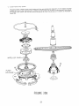
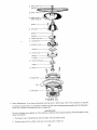
Motor
and
Pump
Assembly
__
NUT-
PUMP
PPER
HOUSING
IMPELLER
MACERATOR
IMPELLER
PUMP
BLADE
SHROUD
LOWER
IMPELLER
HOUSING
LOWER
SLINGER
SEAL
MOTOR
AND
PUMP
ASSEMBLY
FIGURE27
27
(ASSEMBLED)
t:_._
SCREW
WASHER
UPPER
IMPELLER
MACERATOR
SPACER
SHROUD
6
BLADE
5
PLATE
4
._._------_
PU M P PLATE
'
PUMP
GASKET
O RING
3
'(_
LOWER
2 SEAL
IMPELLER
SHIMS
MP
GASKET
SCREW-_
PUMP HOUSING
LOWER
RING
CLAM
SCR
FAN
SLING
FIGURE30A
B,
Pump Assembly
The pump assembly consists of the following components (Refer to Figure 3OA ]
1.
Pump housingor casting which consistsof an upper and lower parL |t attaches directly to the main motor and
the tub,
The upper housing directs water from the upper impeller into the spray arm
2,
,..CharSeal- Provides a water tight seal which prevents water from leaking from he pump housing at the motor
shaft, The seal consists of two parts, The rubber mounted carbon seal is seated into the pump housing and the
rubber mounted ceramic seal fits into the lower impeller.
29
A
Main Motor
and Relay
Most of the dishwashers
use 3450 RPM,
These motors utilize an external
built-in overload protector
120V 60 Hz reversible
type motor
to drive the pump
start relay and have two start or phase windings,
Direction of rotation of the armature
switch contacts
See Figure 28
or rotor is determined
by the start winding
:_N
1
DYE
mLE_
impellers
a main or run winding
selected
through
and a
the timer
I
!
I
!
I
_LU
!
|PMASE
W_
I
,
I
T_ME:R
I
FIGURE28
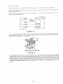
The relay is normally open with its coil connected in series with the main winding of the motor, and its switch contacts connected
in series with the motor slart winding
(Since the relay is a gravity type device, it must be
mounted in an upright poshion ) See Figure 29.
BOTTOM
OF RELAY
FIGURE29
When voltage is applied to the motor, as during the wash, rinse and drain periods of the dishwashing
cycle, fi_e
momemary
high current to the main winding energizes the relay solenoid
The solenoid plunger is lifted, closing
the switch contacts
The start winding is energized through the timer and relay contacts and the motor armature
begins to rotate_ As 1he motor approaches normal running speed, the current in the main winding,
and in the
solenoid diminishes.
When the current through the start relay drops below t0 amps the weight of the plunger
overcomes the weakening magnetic force of the solenoid coil and "drops out," disconnecting
the motor start
winding
28
3.
Lower]mpellerCirculates the water from the pump housing through the spray tube, or middle and upper arms,
during the wash and rinse cycle
When the motor reverses for the drain cycle, the lower impeller forces the water through the discharge port to
pump the water from Lhe machine
,
5
Pump Plate and Shroud- On dishwashers manufactured
since 1969, a shroud was added to the pump plate, to
further protect the pump assembly from foreign objects.
Blade or MaceratorPulverizes fooa particles and thus enables them to pass through the pump system without
obstructing
the water flow. This eliminates the need for pre-rinsing and a fitter screen
-Upper Impeller-
7.
Circulates
water through-the-upper
pump housing and into the spray arm.
Spray Arm, Nut and Washer- The velocity of the water discharged from the spray arm ports and the angle of
the port opening causes the spray arm to rotate at approximately
25 to 45 R,P.M. The rotation of the spray
arm is essential for proper washing action.
When servicing the pump assembly, always check the spray arm for proper operation. It must turn freely on the pump
housing If binding is evident, check the following: (Refer to Figure 15)
!..
Check the mounting
holes in the arm for roundness. ]f evidence of distortion
2.
Check for possible binding on the pump housing. Plastics occasionally
binding is encountered, replace the upper pump housing..
3.
Check to be sure the nut is properly installed
arm to the pump housing,
4.
Check for a split spray arm. A split seam will reduce the efficiency
seal or blower housing.
have a tendency
to the spray arm. An improperly
30
is present,
installed
replace the spray arm
to swell or "grow.,"
[f
nut will lock the spray
of the arm and may cause a leak at the door
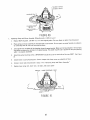
2 Level Tower Pump
5y,srem
•'
m housin
with the recirculating
pot1 c osed off For this reason ;he bwer
This pump sysIern utlt_z,es a. lower pu _ ......
_g,,-_ t_-,_h_
nressure n the drain line during wash/r!nse
phas?s
im eller has a ring or collar Tltteo arounu i__u _,_,._ -,,Z----dz_
,_ _,_ q I_vRt snrav arm systems as ilius_raieu m
ThPe3-level tower system uses the same pump housing aS _u_ L ,_,,,_ ......
_ Figure 30A
C
IMPELLER
0
PUMP
f_
HOUSING
z_"_;_:_P',_!"",,", ',
FIGURE30B
31
Testing the Motor
and Relay
Start the dishwasher at the beginning of a cycle, and allow the unit to electrically
fill The motor should star1 in a counter-clock-wise
direction (ccw)
D
Motor
Main or Run Winding
advance
through
the first
Check
CA UTION:
Disconnect the power to the machine while connecting the voltmeter in the circuit°
1
Connect a voltmeter in the motor run winding circuit as outlined in Figure 3 f, position
has a connector block, meter must have a probe that can be inserted into the biock
"A " If your motor
ANY
START
sWITCH
_BLuE-YEL
POSITION
"A"
VOLT
METER
rr
uJ
P
0
I-
RUN WINDING
,BLUE-ORANGE
START
RELAY
BLUE-BLACK
CCW
BLUE'RED
RINSE
CW
WASH
DRAIN
WHITE
TIMER
START
START
WHITE
Wit
4'0
wINDING
....
_
F
BLU
MAiN
MOTOR-REVERSIBLE
115V
600
AC
FIGURE31
32
1/3 H R
3450
RPM
ANY
START
SWITCH
-II'-BLUE-YEL
tr
U_
VOLT
RUN
o
START
RELAY
BLUEoBLACK
BLUE-RED
"B"
METER
WINDING
BLUE
RINSE
WHITE
POSITION
-_ORANG
WASH
DRAIN
START
START
WINDING
WINDING
WHITE
RED
BLACK
BLUE-
RUN
WINDING
I _
MAIN
MOTOR-REVERSIBLE
115V
60HZ
/3
H,P,
3450
RPM
AC
FIGURE32
.
Restart. the dishwasher. Voltage at Position "A" indicates voltage to motor-run winding° If the motor does not
"hum," (attempt to start) the run winding is probably open. A continuity check (power off and coupler separated)
between the blue and white motor lead should indicate low resistance. If an open circuit is indicated, replace
the motor.
3.
If no voltage at "A,"
Position "B."
(Figure 3!), then check for voltage at the output side of timer as shown in Figure 32
4.
Continuous voltage at BLU-ORG terminal indicates that timer switch is OK, and the trouble is in the start relay,
wiring, or wiring connections.
If there is no voltage at the BLU-ORG terminal check for voltage at the input side of timer,. (Refer to wiring
diagram for the correct timer terminaL)If power is found at the input terminal then the diner is at fault. If
voltage is not present at input terminat, then problem is somewhere in circuit ahead of timer.. Trace circuit for
cause and make the necessary repairs,.
33
, ÷BLO,,ET
,,
STARTW,T,C
E
POSITION
"C"
A"V
WH,TE
VOLT
METER
wtsD'iN6 '......
O
t-
_TAR. T
RELAY
.,_[..BLUE-ORANGE
TIMER"
L
BLUE-BLACK
CCW
BLUE-RED
RINSE
CW
WASH
DRAIN
START
START
W H IT E
I
t
WIN
O
WINDING
I
"""
'
[-7
j
BLACK
BLUE-
RUN
WINDING
%._
MAIN
MOTOR-REVERSIBLE
115V
6OHZ
1/3
H
P,
3450
RPM
AC
FIGURE33
Motor Start Circuit (Wash and Rinse Cycle)
t.
Check the voltage as shown in Figure 33 Position "C,"
NOTE:
Momentary voltage wilt be noted at the instant voltage is appfiad to motor run windin_
,
tf no voltage is noted at Position "C" at the instant voltage is applied to motor run winding and a slight humming
noise is heard from the motor; turn the dishwasher off, and remove Blue-Yellow lead wire from terminal "S"
on the start relay..Move the lead on the voltmeter from the white wire to the blue-yellow lead that you removed
from relay. Make a continuity check of this circuit. An open circuit indicates a defective timer or an open wire
in this circuit. If this circuit is "good," the relay is defective.
If voltage is continuous at Position "C" for 2 to 3 seconds, then turn the dishwasher off and remove the
blue-yellow lead from the start relayo Check continuity between terminal "S" and "L" on the relay, A reading
indicates stuck contact and the relay must be replaced. When this condition is encountered, the motor wi, run
for 8 to 10 seconds before the overload protector opens the motor circuit.
4.
F,
If voltage is present at Position "C," and the motor hums but will not start, the start winding is open and the
motor must be replaced_
Motor 5tart Circuit (Drain Cycle)
To check the drain start circuit, advance the timer to the drain cycle and repeat the procedure described for the
wash start circuit with exceptions noted below:
34
t
Connect
the meter leads to the red motor
lead and any white,
2
Timer contacts for the drain phase are BLU-YELLOW to BLU-RED.
Figure34 is a diagram of the motor circuit Note that the drain or wash start winding is energized through separate
timer contacts Therefore, failure of the motor to start in either the drain or wash cycle may be caused by a defective
timer and not a defective motor.
NO TE
_Vhen.checkingan e/ectricat cJrcuiZ,atways exercise extreme cautiOr_ and refer to the wiring diagram if availabfe. ..
115 VOLT
SUPPLY
T
MOTOR
I
START
RELAY
[
__
B_O'ORG Ir__-u--'_
__I
--- ---_-7
!
k
!
I
DRAIN
,,,,,,,,,,,,
WASH
........
BLu ED
WHITE
LI__._<_
...............................
_.
WHITE
TIMER
(PARTIAL)
i i r-- ----7
i
IBLK I
WASHPHASE
--i__
!
_.
!,,_ IR_D!
_°_'"
I
I
!
I
i°R_....
NYLON
CONNECTOR
OR CONNECTED
DIRECTLY
BLOCK
OF DISHWASHER
1/3
_,.
J
I
-----J
H.R
TO TERMINAL
FIGURE34
35
P"_
MOTOR
TERMINAL
TERMINAL
/
TERMINAL
" !__"
FIGURE35
G
After
the Main Motor
has been tested
and proven good, the motor
1.
Connect the machine to electrical
2
Advance the timer to the beginning of a wash or drain cycle,
relay may be checked as follows:
power.
Set your voltmeter to the 250V, AC scale and connect the leads to terminals "S" and "L" of the starting relay
(Figure 35), Apply power to the machine, If the motor hums and voitage is indicated on th_ meter, the relay
contacts are not closing and the retay must be replaced If the motor does not hum, disconnect the power and
make a continuity check of the retay coif (terminals L to M) before checking the leads and timer
36
2
SUMP
(SOME
MODELS)
SCREW
3
DIFFUSER
SCREW
wA
s.ER
4
UPPER
tMPELLER_
4
MACERATOR
4
SPACER
¢_
PLATE
__
SHROUD
PUMP
PLATE
GASKET-b
RING
LOWER
IMPELLER
5
1
6
GASKET
6
MOTOR
I
FIGURE36
H
Motor
Replacement
(If you have a dishwasher
manufactured
in 1978 or later, refer to the procedure
To replace the main motor, it is necessary to remove the motor and circulating
Follow the procedure as outlined and refer to Figure 36-
Do not
electrical
attempt
power,
any
repairs
wires, circulating
on the
IMPORTANT:
machine
without
first
Disconnect
hose and drain hoses from the pump casting,
2
Remove spray arm nut, washer, spray arm, and sump cover if used, (2)
37
pump assembly from the dishwasher.
disconnecting
1
on Page 40)
the
dishwasher
from
3
Remove
upper pump housing
4
Remove
upper impeller,
5
Remove
lower impeller
6
Detach
7
Remove pump housing from motor (4 thru-bolts at base of motor
mark position of pump housing in re,at;on to motor
8
lnstalt housing in same position on replacement motor
IMPORTANT!
The motor,shaft
must be accurately
centered t;,_the pump housing for r_roper operation oN the pump To aasure precise centering, use Service Tool
803923 as Illustrated in Figure 37, before tightening
thru bolts (Available through Sears Parts Department )
9
After the pump housing has been secured to replacement motor, it is necessary to determine the correct number of shim washers to be used between the fower impeller and the motor shaft Shim_ axe required to insure
correct mating pre£aure of the water seals
To determine the number of shims required, hold shim gauge
(furnished with kit) firmly on surface of pump housing as shown in Figure 37 (Note: Shim gauge should not be
on top of gasket )
motor
(diffuser)
macerator
and seals
and pump housing
The shim washers are t/32
(3}
blade, spacer plale, and pump plate
(4]
(5}
assembly
inch thick
Do not over shim by allowing
cover,
and gaskets from
Fill the space between
tub
(8 screws)
or 4 short
(6)
bolts at top of bell housing)
the motor shaft and shim gauge with the shims
CA U T/OiM:
the gauge to raise above the pump housing surface.
38
and
CENTER
WITH
MOTOR SHAFT
SERVICE
WITH PUMP HOUSING
TOOL 803923--7
/
M
,!' ......
] ......
3____/
f
FIGURE37
SHIM
GAUGE
807077_
.,p'--_
/
_
RAISE
GASKET
EDGES
OF
TO ALLOW
PUMP
GAUGE HOUSING
TO SEAT
SURFACE
ON
FIGURE38
10 Before repiacqng the required shims and lower impeller on the motor shaft, carefully
examine the mating surfaces of the lower impeller shaft seal (white ceramic) and the pump housing seal (black carbon) These surfaces
should be perfectly smooth and polished in appearance
If either appears scratched,
pitted or damaged in any
fashion, the seal must be replaced otherwise a leak may occur
Clean seal cavity
11
thoroughly
Install
the lower seal. Use service tool 803923.
Fasten motor pump housing assembly to tub
12. Re-assemble remaining
Be sure
damage
pump components
Be sure casting is clean and a new gasket is used
in reverse order of removal
IMPORTANT:
the relay furnished
in the kit is used with
the replacement
to the motor can result!
Carefully
review
the instructions
39
motor,
otherwise,
serious
packed
with the motor
J
Motor
]nstaltation
1,
Place motor on floor in proper position beneath mounting
attached to motor )
hole in tub (See Figure39t
2
Insert 2 guide pins _:'through mounting holes in tub and into corresponding
attach
(Pump housing and gasket
screw holes in p_mp housing
_'Guide pins are made by cutting 2 pieces of heavy gauge wire about 6- long They are not required
they do sirnptify installation
f
However,
,,
--ou D p Nst
I1
ROD
FIGURE39
K
.3
Temporarily
attach
upper impeUer to motor
4,,
Place gasket and cover ring over guide pins in position
inside tub,
5,
Grasp impeller and rift motor
beneath tub
6
Holding motor in position,
7,
Remove guide pinsand upper impellerand complete installation
of allattach screws
Removing Pump and Motor
straight
shaft with screw.
up into position
install two of the attach
Assembly
(Manufactured
screws direcdy
(See Figure 39)
across from each other,
in 1978 or Later)
The motor and pump assembly has been redesigned to allow removal through
that the following procedure be used to remove and replace this assembly.
the inside of the tub, It is important
1,
Shut off electrical power to the dishwasher.
2.
Remove accesspanel and toe plate,
3,
Disconnect hosesfrom pump housing ports,,
4
Disconnect motor electrical leads from terminal block and relay.
5,
Remove the lower rack and lower spray arm,
6,
Remove 6 pump mounting screws (Some housings may have 10 screws)
7
Separate halves of clamping ring from _mp housing (access compartment), See Figure 40
8
Pump and motor assembly can now be lifted out from inside the tub,
4O
;KET
.GASKET
807709
807710
LOCATING
CLAMPING
807T12
RING
PUMP HOU
807711
FIGURE
40
L_
Replacing
Pump and Motor
Assembly
gasket, DO NOT
(Manufaclured
in ]g78
1,,
Replace 8077:t0
2,
Place pump and motor assembly in mounting
to connecting ends of drain and recircuiating
3,
Join together the two halves of the clamping ring on the pump housing Make sure the locating pins in the clamping
ring halves are inserted in the holes in the pump housing° The joined ring will stay in position on the pump housing
when it is properly assembled,
the pump mounting
try to re-use original
or Later)
gasket, Be sure ridges on gasket face downward
hole in tub bottom.
hoses
4,
Install
4'1
screws/MPORTANT,"/nstall
5,
Attach
6,
Connect
7.,
Replace lower spray arm, lower rack, toe plate,
Be sure ports on pump housing are adjacent
one screw on each side of the ring F]RSS_ See Figure
hoses to pump housing ports., Secure clamps with clamp screw on underside of hose
motor leads disconnected
in Step _4
INSTALL
in "Removing
Pump and Motor
and access panel
IHESE
SCREWS
FIRST
,)
TUB
FIGURE41
41
Assembly,"
Hoses
A.
and
Couplers
Front Opening Portables
Proper routing of hoses for Front Opening Portables is shown in Figure 42
the following operations
Tub removal is not required to perform
FIGURE42
NOTE:
Tub
is
removed
only
to
show
location
and
routinB
of
hoses
To replace the Fill Hose:
1,
Lay unit on its back,
2,
Disconnect
3.
Stand upright,
4,
Detach saddle hose clamp
5
Pull inlet hose up and out of cabinet.
6.
Disconnect
inlet hose at inlet valve
remove top,
inlet hose from coupler,
Reinstall new inlet hose in reverse of the above - Be certain routing is proper and that there are no twists
in the hose. Check hose connections for leaks and test movement of hose in and out of cabinet.
NO TE:
On some models, both the fill hose and drain hose are permanently
attached
or kinks
to the coupler.
To replace the Drain Hose:
_,
It is best to leave unit in upright, position and remove access panel
2,
Disconnect drain hose from pump casting - CAUTION
water from pump housing and hose.
3.
Disconnect
4,
Remove top assembly
- be prepared to catch approximately
fill hose at inlet (still standing upright].
42
one Q) quart of
5.
Remove hose saddle
6.
Remove hoses.
7,
Detach inlet
hose and reattach
it to a new coupler and drain hose assembly
Reinstall coupbr and hose assembly in reverse orden Be Certain routing is proper with no twists
Check connections for leaks and test movement of hoses in and out of cabinet
Adjustment
or kinks in hoses
of Hose Length:
The length of the hose when fuJly extended is approximately 4%" to 5'. Should this appear short or an additional
inch or two be needed, you could take up any slack that may be available in the routing (Figure42),
Be certain
however, that you do not kink or otherwise restrict the hoses.
B
Hose and Coupler Assembly
Replacement
1.
(]8"
compact model)
of fill hose, drain hose and coupler
Disconnect
(See Figure 48),_
power supply
2,
Remove top assembly.
3,
Remove hose and power cord pocket,
4.
Remove saddle bracket,
5o
Tilt
dishwasher
and disconnect
hoses from valve and pump housing,,
During re-assembly, reverse procedure and place saddle clamp approximatley 50 inches from the coupler end of the new
assembly on the drain hose and approximately 48 inches on fill hose°
CORD
POCKET
DISCONNECT
•PUMP
)ISCON
HOUSING
NECT
VALVE
FIGURE43
43
AT-q
_STEP
ATJ
Faucet Coupler
The fill and drain hoses of a portable dishwasher terminate in a faucet coupler Mos! coupler's are equipped with bleed
valves to enable the operator to relieve the water pressure in the fil! hose by depressing the valve button This prevents
splashing when the coupler is disconnected
Coupler Repair
Because of the high cost of replacing complete couplers and coupler/hose assemblies, couplers should be repaired
whenever possible See Figure 44 and 45 for exploded views of 2 faucet coupters and pressure relief valves used in
Sears dishwashers,
COLLAR
SPRING
RING
S_B_
R_ng
_,,
m
B06584
SLEEVE GASKET
S_r_n
7
_:_od
_J_7
HEX_WRENCH
PRESSURE
VALVE
RELIEF-
PRESSURE RELIEF VALVE KIT
FIGURE44
BODY
FIGURE45
The coupler body has a very tong fife In general, it is aging and wear that causes the sleeve (internal)
pressurerelief to fai{
gasket, collar and
If Lhe coltar is worn, the spring is weak or broken, or bali bearings are missing, order a Collar Repair Kit from Sears
Repair Parts DepartmenL Have your model number available when purchasing repair parts
]f the pressure relief valve is not sealing (leaking thru Need hole) obtain a Pressure Relief Kit from Sears You must
have your mode{ number in order to obtain the correct kit. The 2 pressure relief valves used in Sears dishwashers
are shown in Figures 44and 45,.
If water is coming up around the faucet snap adapter, replace SIeeve Gasket 806584.
44
BI-META
CAM
i
FIGURE46
FIGURE47
Dispensers
A.
Detergent DL_penser- B/-Metal Operated
The Bi-Metal trigger usedto releasethe detergent cup locking cam is made of two different metals which arebonded
together The expansion rates of these metals are considerably different,. The trigger bends when heated and releases
the Locking cam, (See Figures 46 and 47.
The Bi-Metal trigger is a low voltage device It is placed in series with the dishwasher heating element Current flowing
through the heating elementis directed by the timer through the trigger mechanism either during or immediately after
the fill period for the second wash The current heats the trigger and the cam is released,
Severa{ different circuits have been used with these devices Always refer to the wiring diagram for tile model you
are servicing in all cases, power is taken from a timer terminal to one terminal of the Bi-Metal The other Bi-Metat
terminal is connected to the red heater lead, usually at the timer The timer switch that normally supplies the heater
power must be open while detergent cup operation takes place
45
FIGURE48
Connecting a voltmeter in series with the Bi-Metal as shown in Figure 48 will permit a quick check of the circuit
If the circuit is good, tine voltage will be indicated when the timer is advanced to the Detergent Dispenser Inclement
with th'e dishwasher connected to a power source_ The Bi-Metal will not heat with the voltmeter connected, due to
the high resistance of tile meten
Failure of the Bi-Metal to operate can usually be traced to a poor connection, faulty contact or an open iead The
Bi-Metal itself is a highly reliable component, If the circuitry is found to be satisfactory,
the latching surfaces of
the cam and trigger should be checked for roughness,
CAUTION:
Do not
apply
line
voltage
across
the
Bi.,Metal,
as this
would
destroy
it,
The Bi-Metal leaf is an integral part of the electric circuit, tf it becomes necessary to touch the leaf for any _eason,
turn off the power to the dishwasher Although the Bi-Metal is a tow voltage component, it is possible to have a
120 volt potential from _he Bi-Metal to ground when the Bi-Metai circuit is open
14 15
3
FIGURE49
46
Ref,
No,
Description
1,
2
3
4
5
6o
7
8
9
10
11
12
13
14.
15,
16
Bi-Metal Trigger
Screw
Screw
Cam
Roll Pin-Cam
Spring-Cam
Spring-Cam-Compression
Nut
Bracket-Actuator
Washer
Bushing
"0" Ring
Shaft
Cup- Detergent
Cover-Cup
"0" Ring
Wetting Agent Dispenser - Bi-Metal Operated
A completely redesigned supply tank and a Bi-Metal release mechanism are features of this wetting agent eispenser,
Elimination of the solenoid reduces the operating noise level of the dispenser_
The door must be fully opened for a few seconds to allow the wetting agent liquid to fill up in a scoop (Figure 50),
DOOR
IN
FULLY OPENED
POStTI
FILL NECK
-SCOOP
WETTING
AGENT LIQUID
FIGURE50
When the door is closed the wetting agent liquid in the scoop then fills the area at the bottom portion'bf the inner
valve stopper and any extra !iquid drains back into the supply tank (Figure 51 ),,
PLUNGER_._
RESERVOIR
WITH
LtOUID
FILLS
FROM
POSITION
SCOOP'"-.--.__
'_
ZXC_S
DOOR
IN CLOSED
ENERGIZED
BIMET
LIFTS PLUNGER
LtOUIO
DRAINS
BACK .J
_NTO
SUPP_._" I
INTO
AL _--N,_.__dL____
FILL NECK
FILL, NEC_ _
FIGURE52
FIGURE51
Thiscontrolled
amount ofwettingagentliquid
at thelowersection
of thestopper
isreleased
intothefill
neckduring
thewater fill
of the4th (last)
rinseonly.(Figure
52)
To check for proper operation, with wetting agent liquid in the supply tank, start the dishwasher in the normal manner,
then manually advance the timer to the fill of the last rinse, The Bi-Metal should lift the stopper either during or
shortlyafter thisfiJl,
The wetting agent willthen flow from the valvearea out to fill
neck for mixing with the rinse
water_
47
Failure of the Bi-Metal to lift can usually be traced to an interruption of its circuit path, which includes the heating
element The rinse injector Bi-Metat is very similar to that for the detergent cup, and it is checked in the same manner,
A voltmeter may be used in series with the Bi-Metal (see Figure 53) to check for an open circuit condition_ Reference
should be made to the proper schematic wiring diagram to locate such a condition
FIGUP,
E 53
CA UTION:
Do not apply line voltage
across
the Bi-Metat
as this would
destroy
it, A voltmeter
across the Bi.Metal
terminal
will indicate
approximately
one volt if operation
is correct
but a poor connection
at the Bi-Metal
terminal
could show
line voltage,
Leaking Wetting
Agent Dispenser - Bi-Metal
Overfilling the wetting agent dispenser can
This liquid will run down the door between
door of the dishwasher does not open past
This can be corrected by raising the front
Type
cause the liquid to be forced past the plunger when the plug is replaced,
the door and outer panel and may drip to the floor Make sure that the
the horizontal position This may cause the wetting agent to leak out,
levelers slightly on undercounter models
48
Timers
A
Timer OperatiOn
D.
ELECTRICAl.
CONTROLS
The timer is the central control point of the electrical components. All timers used on Kenmore Dishwashers are similar
in operation and design. The only difference is in complexity due to the variation in function and features of the various
models
CAM
SWITCH
MOTOR
FIGURE54
All electromechanica!
timers consists of two basic components; a motor, and cam switches, assembled into one unit..
(Figure 54). To fully understand the function and relationship of these two components to one another, it is necessary
to examine each component in more detail
Timer motors may vary slightly in appearance, but each functions in the same manner It is a synchronous-type motor,
similar to those used in electric clocks, with a small pinion which drives a cam through a gear arrangement.
The cam switches are enclosed in a case to protect them from damage and contamination
by foreign particles which
may cause a malfunction
The number of switch contacts and cams varies with the number of functions the dishwasher
performs
The particular shape of the cam varies with the number of switch contacts it controls
switch contact is ctosed_ Figure 55 shows a very simple cam that controls one switch
two increments of the timer cycle Let's assume that this cam is designed for a timer
six deglees (6 °) every sixty seconds The cut-out portion of this cam, therefore, is twelve
contacts are closed for only two minutes during the complete cycle
and the
contact,
that has
degrees,
length of time each
which is closed for
an advancement of
and the cam switch
CAM----/
CAM----.-/
t
FIGURE55
A single metal strip, called a cam follower, (Figure 55) is anchored to each cam switch arm and as the cam turns,
this metal Strip follows the contour of the outer circumference of the cam, thus causing the cam switch arm to make
and break contact at the proper time
In Figure 5B we see a more complicated cam, This cam was designed to control one or possibly two switch arms that
have dual contacts
You will note that this cam has raised, cut-out,
and neutral portions The raised portions
force the cam switch arm against the outer contact and the cut out portions allow the cam switch arm to make
contact with its inner contact. Both contacts are open when the cam follower is on the neutral section of the cam
SWITCH
ARM
CONTACT
CAM
FOLLOWER
. NEUTRAL
SECTION
CAM
CONTACT
_
INNER
OUT
PORTION
-CAM
FOLLOWER
OUTER
CONTACT
€
FIGURE56
49
Selector
Switches
A selector switch on an automatic dishwasher gives the customer the option of choosing the type of wash best suited
to the dish load and type of soil Some economy models have this selection built into the timer The most common type
of cycle selector, however, employs a push button switch which bypasses unwanted portions of a cycle
The pushbutton switch mechanism, although appearing complex because of its many terminals, can be rather simple to
trouble shoot Always refer to the Cycle Selection Switch Functions Chart which is printed with the wiring diagram and
follow the procedure outlined in the following example,
Checking
The 5-Button
Swttch
1
Disconnect
dishwasher
from electrical
power.
2
Detach control
3
Disconnect Leadsfrom the switch and connect leads of ohmmeter to terminals on the switch as they are
designated in the "Cycle Selection Switch Functions" chart, (Figure 57) For example, begin with the first column
under "'Cycle Selection Switch Functions" Connect, one ohmmeter lead to the "1" terminal and the other lead
to the "3" termirial. Press each of the four buttons and compare ohmmeter reading with chart, |f chart shows
switch "OPEN" (0) no continuity should register on ohmmeter when button is pressed. If "CLOSED" (C)
continuity should register on ohmmeter when button is pressed.
panel from inner door panel
Fo!low this checking procedure through all cycle switch positions, being certain the ohmmeter leads are connected
to the proper terminals. Failure of switch to register as shown on the chart indicates a defective switch and it
must be replaced, (Figure57)
NOTE
Some 5elector swztch termma/s are identified
CYCLE SELECTION
SWITCH
SELECTION
R_nse'n
Hold
Normal Wosh _
Power Seal wosh
SWITCH
of digiZ_,
FUNCTION
TC
1 2 I S
C OIC
C C
C_
by colors ihstead
0
OPEN
C CLOSED
C
FIGURE57
Since failure of the machine to function properly can result from failure of one of several components,
the above checks are accurately performed before labeling a selector switch "defective,"
50
be certain
Thermostats
A
Sam-Wash
and
Temperature
or High Temperature
Indicators
Wash/Rin.se
Thermostat
Most dishwashers are equipped with a thermostat to provide for guaranteed hot water in the 2nd Wash and/or Final
Rinse when a Sani-Wash or high temperature wash is selected.. Unless the water temperature is high enough to satisfy
the thermostat,
the thermostat stops the timer until the heater in the machine raises the water temperature enough
to satisfy the thermostat
If the water temperature in the tub
does not run, prolonging the rinse
temperature is reached, the bimetal
to the time_- m6tor) and the timer
is below the thermostat
setting the switch remains open and the timer motor
cycle until the water temperature
rises to the thermostat
setting When this
strip within the thermostat deflects and doses the contacts (dosing the circuit
resumes operation to complete the dishwashing cycle; See Figure 58
-- THERMOSTAT
INSTALLED
"MYLAR
JACKET
CROSS
SECTION
OF
THERMOSTAT
FIGURE58
The heater in the machine will raise the water temperature approximately one degree per minute Thus, if the water
is 135 degrees at the start of the Second Wash or Fourth Rinse and the thermostat
is calibrated to 150 degrees,
the timer will stop for approximately
15 minutes in the Second Wash or Fourth Rinse (or both) while the water is
being heated, During the time that the thermostat
is calling for'heat, there is no power to the timer motor although
the wash system continues to function
Depending
on the model dishwasher,
the thermostat
may be calibrated at 140° to 150 ° Some Lady Kenmore
models contained 2 thermostats; one which is a round disk type, and the other which is of a tubular design The
disk type is calibrated for t50 °, and the tubular type is calibrated for 1200
B_
Checking Thermostat Operation
If the second wash or final rinse cycle is not delayed (when a Sani-Cyde has been selected), despite a temperature
of less than 130 ° F in the tub:
1,
Check for incorrect wiring (use schematic).
2,
Check for a defective thermostat
3.
Check for short in thermostat circuit.
4
Check for too low a calibration of the thermostat, Thermostat calibration may be determined by measuring the
temperature of the water expelled from the machine following a thermostatic delay
Contacts should be open when cold,
5t
If the second wash or 'final rinse phase is prolonged for an excessive amount
hotter than necessary:
1.
Check for too high calibration,,
2,
Check the thermostat
3
Check to see that
4.
Check the heating etemenL
circuit
(Follow
same procedure as outlined
for correct
a faulty
to become
on the previous page )
wiring
power is applied to one terminal
If 1 and 2 are satisfactory,
of time, causing the water
thermostat
of thermostat
by the timer at the proper time.,
is indicated and should be repiacedo
CA U TION:
Care should
be taken
when installing
a replacement
strain
or pressure
on the body of the thermostat,
position
by a clamp
on the wire leads,
thermostat
so as not to place any
Note that the thermostat
is held in
Some Kenmore Dishwashers, both portable and built-in, are equipped with sensing devices to indicate to the user
the temperature of the water within the machine. The water temperature
will fall within the ranges of "Cool,"
"Normal,"
or "SanY' and wilt be indicated by lights on the console as shown in Figure 59.
TEMPERATURE
DRY TIME
SELECTOR
INDICATOR LIGHT
TEMPERATURE
DELAY
FIGURE59
The "coot" thermostat (Figure 60 )is a single pole single throw temperature
(Figure 61) is a single pole double throw switch
C©OL
THERMOS'fAT
'
'SANI'
THER MOSTAT
@
)
FIGUREGO
52
I
controlled
switch
The "sani"
thermostat
Since the thermostats
secured firmly against
are subjected to varying conditions within the home, it is extremely important
the door or tub of the dishwasher in order to accurately sense the internal
TEMPERATURE SENSfNG
SURFACE-:'::
........
that they be
temperature
!iii ii!ii!!i!i
i'.ilit :
i;i:iiii:i:ii
i;i:ii:::i!:!
FIGURE61
The purpose of the lights is to indicate 1o the user o1 the dishwasher whether the hot water supplied to the machine
is hot enough to produce good dishwashing results The "Cool" tight ,will remain on until the water temperature
in
the dishwasher reaches 1400 at which time the light switches from "Cool" to "Normal "
Dishwashing
detergents
state that temperatures
delivered to the inlet valve must be at least t40 degrees
This
minimum temperature
is required because of the severe drop in water temperature
as waler enters a cold steel tub :.
and [he fact that it must "heat up" the tub interior and its contents before it can be expeci_ed to maintain the in)et
water temperature
For example; if water at the tap measures 140 degrees upon entrance into a cold dishwasher, this water temperature
wil! drop to approximately
115 degrees or tess depending on the size of the load and the kind of dishware in the load
See Figure 62 As you can readily see, this would give only minimal warm water in the first wash to activate the
delergent
The hotter the water is on the first fill, the quicker you will heat the tub and contents,
and the better
you wilt maintain the heat
Long water runs, hot water pipes that pass through concrete slabs and crawl spaces will tend to cool the water
between fills Undercounter
units that have an outside wall across the side or back tend to keep the tub cool
Therefore, always make yourself aware of all the conditions that can affect water temperature in your home
Also remember that any test involving
in place throughout
the testing
Water Heat Option
thermostats
130°/140
and sensing devices must be done with all panel and components
°
Some models produced beginning in 1982 have a water heat option controlled by a 130°/140 ° iubular
stat These models delay in the 2rid rinse, 2nd wash, and final rinse if the thermostat
is not satisfied
Hot Rinse Option
type thermo-
150 °
Some models have a hol rinse option in the final rinse This functions
final rinse The hot rinse option is controlled through a 150° tubular
High Limit Thermostat
exactly Iike the sani-lemp
thermostat
option
of 150 ° in the -
180°
Models produced after 1982 have a 180° high limit thermostat
This is a tubular type; it is normally
the circuit to the heater when the temperature rating is reached
On some models this thermostat
by a thermal fuse rated at 1O0°C This is located in the thermostat
bracket on the door liner
53
closed ft breaks
may be reptaced
TEMPERATURE
WATER
OPERATING
CHARACTERISTICS
iNLET
WATER
TEMR-140°F
W
z
!1
1stWASH
]st RtNSE
nlll
2naRIN
WASH
3rd RIN
4tfi RINSE
Water
FIGURE62
Hot
Heat
Rinse
DRY
Option
Option
In Figure 62, inlel water temperature is at 140 degrees constant
Operation with t40 degree inlet water temperalure, is adequate and will do a good job of washing dishes Notice how water heat and ho_ rinse options will
function with 140 ° inlet temperature
C
SanM4/ash
Delay Circuit
Figure 63A shows the circuit at the fourth rinse when the Sent-Wash cycle has been selected and the water temperature is below the indicated Sani temperature
[}50 degrees)
The swilch to the timer motor has opened;
therefore, the timer cannol advance The temperature delay light wiiJ be energized through the Sani-Wash switch
and the coil of the motor (Current flow through the coils will be insufficient to cause the motor to run )
During this delay period, the water continues td circulate and rinse the dishes while
raises the temperature of the water When the "Sani"
temperature
is reached,
closes its contact one to two, the delay light goes out, the "sent" indicator light
energized through contact 1 and 2 of the thermostat
for one minute, after which
closes The timer motor remains energized for the remainder of the rinse and dry
For models without temperature indicator _ights, the sani delay function
the thermostat
is a single pole, single throw switch
54
the heating element gradually
the double throw thermostat
glows, and the timer motor is
the timer motor switch again
cycle
operates in the same manner,
however,
SANITIZE
POWER
DELAY
SANI
LIGHT
WASH
CYCLE
3
FIGURE63A
D
Water
heat
and
hot
rinse
circuits
55
CIRCUIT
SELECTOR
In Iigure 63B the water heat circuit is shown with the solid line The dashed line indicates the delay light circuit The
dotted line is an alternate circuit with the hot rinse option oft When the water heat thermostat
is closed, the timer
continues to advance, and the delay light goes out
I
@
.....
d
FIGURE63B
56
in figure 63C the hot rinse circuit is shown by a solid line The dashed line indicates
light glows and the timer is stalled until the hot rinse thermostat
closes
I
I
1
!
FIGURE
G3C
57
the delay light circuit
The delay
Figure 63D iliustrales the circuits involved when both water heat and hot rinse are selected
rinse is controlled
in this case by the higher rated thermostat, hot rinse
_ :_<___,__..'__'!t
FIGURE
63D
58
The detay in the final
Door
A.
and
Float
Switches
Door Latches and Switches
Door switches are safety devices which prevent the dishwasher from operating while the door is open The switch
is the first component in the circuit, All other components are in series with the door switch and aiI machine functions
cease when the door is opened,
The door switch is actuated by the fatch mechanism See Figure 64 and 65 A voltage check of the switch using a
volt-ohm meter will quickly isolate a defectivecomponent
WHF[E
_TCH
Closed
ON
Posit_on
FIGURE64
CAUTtOff:_E SURETHETWOW_RESFROM
DOORSWITCHARELOOPEDAWAYFROM
£ATCHM]ECHAN1SM
AND IAPEDINlO
,,/WIRE HARNESSAS SHOWN
FIGURE65
59
Float Switches
The float switch is wired in the circuit between the timer and the water inlet valve The purpose of the float switch
is to prevent an overflow in the event the drain system should fail or the timer should stick in the fil! position allowing
too much water to enter the tub It will not prevent an overflow should the water inlet valve develop a mechanical
defect
The switch is operated by a floe1 localed m 1he 1lib _F_qHrP65) whirh ri,_S with the waler level At e predeler
mined level, before an overflow can occur, the float opens the switch contacts and breaks the circuit to the
water inlet valve
"f he swftch
_s e normally
open m_cro sw_tch which
_s held closed by the weight
of the float
The ftoal switch may be checked by placing the leads from an ohmmeter across 1he switch terminals
lowering the float should cause the switch contacts to close or open the circuit
Raising and
NOTE:
Almost every dishwasher on the market has a timed fil/ period Some have a pressure switch for overftow proo
tection, others have a float switch Normally an inlet valve should remain open for 45 to 90 seconds. There are,
however, instance_ where a machtne will lilt so rapidly [because of high water pressure] that the overflow
swztch will cut off the inlet valve to prevent an overflow
This will result in a pause between hfl valve cul off
and the start of the wash or rinse cycle This is normal and no adjustment should be made
NORMAL CHARGE 9 QTS
OVER
FLO
SWITCH
FIGURE
66
60
E. WIRING
DIAGRAMS
AND ESTER LINE
(CYCLE) CHARTS
To propedy diagnose electrical problems associated with your dishwasher,
it is important for you to understand the
wiring diagram and estertine chart which is located on the tech sheet inside the machine console, These diagrams vary
from model to model depending on the particular machine's features, but a basic knowledge
of one diagram will
enable you to understand other diagrams
The wiring diagram, as shown in Figure 67, is e typical line schematic which shows eli the electrical circuits involved
Most dishwasher wiring diagrams have arrows or the symbols BK and W at the top of the diagram
This represents
the connection to electrical power The line marked W extends down the right side o1"the diagram and is known as
the neutral side of the electrical system Note that this line connects directly to one side of each electrical component
of the dishwasher without any controlling
switch
WH
FIGURE
67
B!
The line shown as BK extends to the tell and is known as the "hot side" of the electrical system It provides a circuit
to the door switch and ulumately to all electrically operated components
through the timer switches
You will note
that dashed lines enclose the timer, cycle selector, and door switches
This is to indicate that these switches are
inside the component
structure
Ester
Line
Charts
To use the wiring diagram in diagnosis, i_ is very important that you understand the Ester tine charts This chart, as
shown in Figure68,
is used to determine when and forhow
tong a particular circuit or circuits are energized
The
heavy shaded bars represent the period of lime the internal switches of the timer are closed
COLOR CODE
BN
_D
0
0
IQ
GY
0
"tO
_N
D'fOY
z_
0
10
_
Q
'tO
P_,
B_
_oe
5_
_-z10
O
10
B_
l_
Y
v
P
t_u
O
10
BL_
10
DU
I_t
R
6O
R_NSE
N
HOLD
NORMAL
WASH
POTS
&
PANS
SANI
WASH
Most circuits pass through the selector switch The switch functions are shown at the lower left corner of the esteriine
chart A power loss at the input side of the timer may be caused by a defective selector switch,
Input and output terminals of the timer are easily determined by referring to the order of timer terminal markings at
the Ester fine charts' left side The input color listed first, and the output color listed last. To completely understand
the relationship between the wiring diagram and esterline chart, refer to the following example and Figures 69 and 70,
Example
Begin at the fill phase of the cycle when a normal wash has been selected. The following timer switch contacts are now
closed(Refer to FigureGg;
• Power Bus I - Switch 1
• Timer Motor- Switch I0
• Water Valve - Switch 24
B2
FILL PHASE"
NORMAL CYCLE
COLO_
CODE
Dr=
,t_
o
D_
To
o
"_-]_
D
To
1N
otDv
_
__-%_'1 ,
-./.4..
o
_o P_D_
_
'r
B_
1on
v to
By
._, /" I!
1
_
,
o
* l_
X
X
....
I
3
NOR MA[WA_
0
_015
& PAN_
S_NI
WASH
22
63
I
"--_._.J"
:
Note that the switch numbers on the Ester line chart
correspond to switch numbers on the wiring diagram,
At the end of the fill phase, the water valve opens as shown by the Ester line chart, and the timer contacts
are now closed (Refer !o Figure 70 )
•
•
•
•
•
Power
Timer
Motor
Phase
Heater
listed below
Bus 1 - Switch "i
Motor - Switch 10
Power- Switch 20
Wash - Switch 2_
- Switch 23
The machine is now in its first wash The switch on the motor start, relay closes and then opens after the motor reaches
its operating speed As you progress from left to right across the Ester line chart, it is easy to determine which timer
contacts are closed at any point in the cycle This information can then be related to the wiring diagram
Studying and learning has no value until it is applied
machine malfunction
For example, let us assume we have selected a "Normal
the easy and obvious first
It is necessary to follow a step-by-step
procedure
to diagnose a
Wash" and the dishwasher will not fill. A rule is to always check
1,
is there power to the machine? Be sure the proper connection been has made to the electrical
for a tripped circuit breaker or blown fuse
2.
Make sure the water
3,
Check to be certain the door latch is closed,
4,
Check to be certain the timer dial has been advanced to the point where the indicator
delay will be present before the machine begins to fill,
5,
Check the float to be sure it is not stuck, it must move freely
supply to the machine is turned
64
supply, Also check
on,
light comes on A short
FIRST WASH
NORMAL CYCLE
i
,I III
FIGURE
70
RELAY SWITCH OPENS AFTER
MOTOR STARTS
B5
Voltage
Checks
CA U TION
When
making
voltage
checks,
remember
that the machine
extreme
caution
to not physically
touch any bare contacts
checks..
is connected
to a live power
source
Use
or wiring
terminals
when making
voltage
When all the previous steps for normal operation have been checked and the machine stitl does not tilt. turn to the wiring
diagram and Ester line chart which is usually packed {n the machine console Using a vottmeter set on a scab that will
measure at least 120 volts AC, connect one lead to a white (common) terminal and the other lead to point = 1 indicated
in Figure 71 With the timer set to a fill portion of the cycle, and the door s_itch closed, 120 volts AC should be present
A slight humming sound should also be present which indicates that the water valve solenoid is energized if these two
conditions are present, check for blockage or a stuck plunger with]n the fill valve Clean or replace the valve as necessary
if 120 volts AC is not present, move the tead to point =2 shown on Figure 71 No voltage at this point would indicate
a broken or disconnected wire, or a defective timer ]f 120 Votts AC is present, the float switch is defective or the wire
between the float switch and water value is defective
0
v
_u
=*
o-
2?
I
FIGURE7i
66
_o '
L.>_'-
..........
To determine if the timer is defective, attach the voltmeter lead to point #3 shown in Figure "/! leaving the other
voltmeter lead attached to the white or common terminal, 120 Volts AC present at this point indicates that the timer
is not defective. No voltage at this point wouid indicate a defective timer, NOTE: Always be certain the timer is set to
the portion of the cycle in question when making voltage checks, Some segments of the cycle have a short duration and
can be misse&
Continuity
Check
.........
An alternate method of checking the timer is to disconnect the machine from the power source and make a continuity
check_This continuitycheck of timer switches may be made by disconnectingthe lead from the timer terminals in question,
and connecting the leads from your ohmmeter across the timer switch_
For example, if the motor will not start in the wash cycle, disconnect power from the machine and remove the wire from
the timer's BU_BK terminal (Figure 71)_ Connect one ohmmeter toad to BU-BK and the other to BU-Y With the timer
knob rotated to the wash phase of the cycle, the ohmmeter shoutd register continuity or no resistance, If the timer switch
is defecUve the meter will indicate an open circuit or infinite resistance,
All timer switches may be checked in the same manner by referring to the Ester line chart and wiring diagram, and
connectng the ohmmeter leads to the correct combination of terminaIs. NOTE: Correct interpretation of the meter reading
is important. A continuity check of a switch should indicate no resistance.. A resistance reading of other than zero or
infinity could be the result of damaged or burnt contacts which would reduce power to the component, Do not make a
continuity check with an ohmmeter when the machine is connected to a live eIectrical circuit. Damage to the meter wilt
result.
Other electrical componentsin the dishwasher may be checkedin the same manner. Some resistance wil! be noted when
checking motors, coils and heating elements,
67
F. MECHANICAL
Door
SYSTEM
Assemblies
The door should never require adjustment,
N1isa[ignment between the door and cabinet on built-in machines is
usually a result of improper positioning of the attach brackets to the counter top Reposition the brackets to align
the door to the tub
A slight adjustment
to increase or decrease gasket pressure between the doer and tub may be made by. removing
or installing shims behind the door strike (Caution - Addition of shims on a new dishwasher to make latching easier
may result in a leak after the gasket has taken a "set")
Bending of the door latch usually results from attempting
to
latch the door before il is fully closed
Spring tension is set a_ [he factory for the standard dishwasher door Too much tension will not aliow the door to
remain in the fully opened position
Too little tension will cause the door to fall open when the latch is released. Spring
tension may require adjustment if a wood ot metal inserts are added or removed in the door See Figure 72
FIGURE
72
A
One Piece Outer Door Control
Panel
On some dishwashers the outer door panel and control panel have been combined 1o form one common part :that
is removable from the inner door ,without need for disconnecting
wires This leaves the dishwasher
entireiy
operable
To gain entry to the area behind this piece housing the timer,
e_c, proceed as follows and refer to Figure 73:
power
selector switch,
injectors,
door switch,
thermostat,
t
Disconnect
supply to dishwasher
2
Remove
3
Lower (open) the complete door assembly and remove the six 16) screws attaching the outer door control
panel to the inner porcelain door, (NOTE: This step should be done, using clamps or a "knee brace" to retain
the panel during screw removal t
4
Allow
5
Remove
6
Place the outer panel on floor adjacenl
7
Check wire connections
8
Proceed
with testing
9
Reverse
procedure
the latch knob attachment
the complete
door assembly
screw
to close slowly
the outer panel and rotate it from
NO TE:
If the removal
the left to the right
to the dishwasher
t80 ° in the upright
in the upright
position
position
on all components
and repair
1or replacement
of _he access panel is hkefy, # should be done prior
B8
_o outer panel removal
FIGURE73
B_
Two Piece Outer Door Control
Panel
The 2-piece outer door has a control panel which is separate from the remainder of the door. Removal of lower panel
is accomplished in somewhat the same manner as the one-piece door panel The control panel wh}ch houses the timer
and selector switches may be serviced by opening the door and removing the screws which hold it in place (Figure
74), When removing either panel, be sure to remove only those screws which hold that panel
FIGURE74
B9
Anti: Tilt Assembly38" Portable Models
A new anti-tilL device was designed for the 18" dishwasher to prevent overturning with 50 pounds supported on an
open door.
To remove; refer to Figure 75
1.
Disconnect power supply
2
Place dishwasher on its back,
3,
Remove spring attaching anti-tilt
4.
Remove cable from anti-tilt
5
Remove screws attaching foot and shim to the frame assembly
6
Reverse procedure for replacement.
arm to the rear caster bracket.
arm,,
REAR CASTER
STEP
BRACKET'
STEP4
£RING
NER
SHIM
COUNTERBALANCE
ARM-
FIGURE
D
"C" Arm Replacement
]8
Dishwashers
I
Remove spring and cable from "C"
arm
(Figure 76)
2
Remove two (2) screws that hoid "C" arm to inner door,
3
Remove bottom
4
Remove plastic "C"
5
Remove "C" arm pin from hole in hinge bracket assembty
6
Push "C" arm through
7
Reverse procedure to replace
two (2) screws holding hinge bracket
assembly to wrapper
arm guide
the notched area of the tub flange
7O
S_EP 3
STEP 2 --
S_p4_
PLASTIC
_
STEP 1
GUID_
NGE BRACKET
5
C ARM
PIN
FIGURE76
Racks
To remove the upper rack only. remove the end caps at the front
the end caps in place
of the slides by straightening
Refer to Figure 77,
END
CAP
_"
RACK
FIGURE77
To remove the upper racks and slides (square slide out type) proceed as follows
I
Detach upper front and lower rear roller on each side
2
Remove racks by raising rack and slides until slides will pass the new rollers
(Figure78)
11
(Figure79)
the metal tabs holding
UPPER FRONT
LOWER REAR ROLLER
FIGURE78
FIGURE79
'Tub Gaskets
The tub gasket is a one-piec_ gasket as shown in Figure 80, The tub gasket is fastened with stainless steel clips,, The
illustrations, figures 81 thru 83 show how these clips are removed and replaced on sides and top A gasket junction wire
and one or two clips secure the gasket at the bottom dam
FIGURESO
The following
1
instructions
apply to remova! and _eplacement of the dishwasher
To remove gasket, insert a small thin screwdriver
See Figure 81
tub gasket
blade under flange of the gasket attach
12
cfip and press outward
Attach
Clip
/i_._ScrewdrJver
Press Outward
Gasket
,_
/_Li)P
_-_'
ress Outward
Flange Attach
/
__ Lr_
_
Tub Slot
Gasket
11
FIGURE8!
2
Attach
d!ps can be positioned
in replacement
gasket and pressed back into tub slot, See Figure 82
TO REPLACE
Apply Pressure To Flange
Of Clip. Press Into Place
lub
Slot_
Attach
_ress
In
Cli p_l
FIGURE82
3,
The replacement gasket must have both bottom front corners positioned tightJy against curved surface of tub
(A-Figure 83) and herd in this position with the two stainless retainer clips located at bottom front of tub
(B-Figure 83) Later models have only ] stainless clip which holds the "U" shaped portion of the junction rod
A
Position
Hump .In Junction
Rod At Butted
Ends Of
Gasket
To Center
Rod In
Bottom
Of Tub,.
B
Sealing
Surface
FIGURE83
"/3
@
FIGURE84
4
A revised vent baffle was introduced in t981. This vent baffle has a white vinyl gasket along the bottom edge
There is no adjustment on this vent baffle The tub gasket has a longer cut-out
section in the bottom with
this vent baffle Most models use this tub gasket/vent
baffle kit for serwce replacement
74
Cord
Reel
The power cord reel bracket is attached
view of this mechanism_
to the side of the cabinet or to the bottom
channel See Figure 85 for a deta{ted
Washer
"Spring
Reloining
Wires
&Bracke!
-Spring
Retoiner
.-.
Place Rep[ocemenl Sprin G
tn Position Shown
mp
Screw_//_
FIGURE85
A
Power Cord and/or
Reel Replacement
for Front
Opening Portables
(SOME
MODELS )
FIGURE8G
NOTE:
Tub Is Removed Only To 5how LocatiOn
Of Power Cord Reel And Cord Housing.
1
Remove the entire top assembly only and set aside,
2
Remove top screws that secure housing and hose guard to cabinet See Figure 86 Lift both pieces up and out
from between tub and cabinet Allow cord to retract or fall to bottom, Lay dishwasher on its back.
75
3
Remove
power
cord reel attach
screws
exposed on left side of cabinet
Install the replacement power cord reel Wind the reel and cord clockwise to achieve the amount of reel windup needed Coil spring should recoil the power cord comptetety when the cord is fully extended
Temporarily
secure the power cord pfug 1o the back side of cabinet and reassemble cord housing and hose guard IHose
guard must be reinstalled )
5
Reptace the top assembly
Casters
Caster Replacement
Use the following
vice Department
Potlable
procedure
Dishwashers
to repair a damaged
caster socket
Obtain
a caster repair kit from
your Sears Ser-
Drill out the four projection welds that anchor the caster sleeve (See FigureD7)
A light tap on the closed end
of the sleeve will dislodge the entire sleeve assembly
it is necessary to remove this sleeve so that the new
easter will rest flush on the support cross piece
2
Insert the caster and fasten
securely
Do not remove the "hat"
By using this method
CA UTION:
shaped portion on the frame. This "'hat" will give added stability.
and strength to the caster.
of replacement,
This procedure can be followed
ment of all four (4) casters
with the nut
you wnl need to replace only the caster in the damaged
on most dishwashers
Very old units with small diameter
wheels
socket
require
replace-
NOTE:
Do not attemp[ to replace casters by merely inserting the new caster m the old sleeve This is not proper and
will cause the machine to be out of level Casters marking the floor can usually be traced to a damaged or
lammed caster assembly
This causes the caster 1o shde rather then roff across the floor
DRILL
BRACKET
THRU
4
&
INDENTED
REMOVE
WELD
SOCKET
*SPOTS
& WASHER
FIGURE87
78
ON
CASTER
(1/z_
DRILL)
NUT
_LARGEWASHER
'-
,f
DISHWASHER
SMALL
FRAME
WASHER
t
/5EARINGS
_CASTER
CASTER
ASSEMBLY
FIGURE88
Tubs
Replacement of a tub requires a complete disassembfyof the dishwasher tf a tub replacement is necessary, we recommend
having it done by a qualified service technician,
f_
77
G. DRYING
Convection
SYSTEM
Method
in the convection method of drying, the air near the energized heating element (hot dry option only) becomes hot and
rises The cooler air fafts to the bottom of the tub where it is heated and rises As the rising warm air passes over the
wet dinnerware,
it is cooled and falls once again to the botlom of the tub A natural convection eurrenl is 'thus established See Figure Bg_
FIGURE89
Some of the moisl, hot air will escape from the dishwasher
and the drying process continues
through
the vents
This air is replaced
by cooler,
drier air
It the "Cool Dry" option is selected with the convection method, improved drying results can be obtained if the door
is unlatched after the final drain phase Allow the dishes to cool before removing them from the dishwasher
If the dishwasher is cycled in the evening and is left closed overnight,
Leaving the door open for a few minutes will dissipate this moisture
7B
moisture
may recondense
on the dishes
Forced
Air
Method
Some dishwashers are equipped with a blower, The blower assembly is located at the right rear bottom of the tub, (Figure
90) and circulates ambient air through the tub cavity during the dry cycle This circulated air is drawn in through Lhe
vent in the door panel, across the dinnerware and into the blower housing where it is mixed with cool dry air before it
is exhausted beneath the machine, Some machines are equipped with a "Hot Dry"/"Cool Dry" or power miser switch
If "Hot Dry" is selected, the heating element is energized during all or part of the drying period,
LADEN AIR
EXHAUSTED
FIGURE90
A_
Servicing the Blower Assembly
The blower motor and blower wheel are mounted to a sub-plate and this assembly can be easity removedas follows:
I.
Detach the leads to the blower motor.
2,
Remove one screw from the motor mounting plate (Figure 91 )
79
GASKET
seRE
t!1 k A sEMBL'
BLOWER
PL A*!E
BLOWE R ASSEMBLY
FIGURE9.!
3.
Move the assembly to the left and lift out..
The blower wheel is pressed onto the motor shaft and can be pried off (carefully) with a screwdriver placed
between the motor mounting plate and the blower wheel When reinstalling the blower wheel to motor shaft
maintain a 3/&6" space between the back side of the blower wheel and the motor mounting plate°
B,,
Checking Blower Operadon
The operation of the fan can be easily checked by setting the control to some portion of the dry period and observing
blower operation,
if the blower motor fails to operate check as follows:
!,
Advance the timer to the Dry position,
2, Check forvoltage
at thequickconnector terminal
block
3
If vo]tage is present, check leads to blower motor. Replace motor if defective.
4
If no voltage is present, consult the wiring diagram and make the necessary checks to determine where the voltage
lossoccured
In the event that the blower housing may have to be removed, proceed as follows:
1 Disconnecl
power
and remove
2
Disconnect
the w}res to the blower
3
Remove
screws
holding
4
Remove
screws
from inside of the tub holding
(Figure 92)
the access panel and toe panels
the internal
motor
ducl
at the terminat
board or quick disconnect
cover to the tub and remove cover
the blower
8O
assembly
block
(some models}
5
Remove
blower
housing
6
Re-install
with
new gasket
Heating
A
assembly
_rom under tub
Elements
Heating Element
The heating element is used to maintain hot water for washing and rinsing operations in some models and to provide
a source of heat for drying the dishes.
B_
Operation
A helical,strand of resistance wire is encased in a sheath with magnesium oxide tightly packed between the wire and
the sheaf:for electrical insulation Heat is generated in the resistance wire when 120 volts AC is applied to it, The
heat is then transmitted through the magnesium oxide and through the sheath to the water or air surrounding it,
See Figure 9'3 for a cut-away view of the heater,
The direct causesfor the element, to malfunction are,
l,
interruption of the electrical circuit to the heating element,,
2,
The helical resistance wire becomes burned or broken
3,
The helical resistance wire short-circuits to the sheath due to breakdown of the magnesium oxide
B1
SHEATH
ELECTRICAL
INSULATION
HEAT(NG
ELEMENT
I!EATERSYMBOL
FIGURE93
Heater
Testing
Connect the dishwasher electrically, Remove the racks from the tub., Advance the timer to the beginning of the "Dry"
cycle, If your dishwasher has a Power Miser Switch be sure it is in the "Hot" position_ Turn the dishwasher on and
allow it to operate for about 3 minutes,
Partially
open the dishwasher
door,, The heating element should be glowing red around its circumference
If the heating element does not show evidence of heating, check voltage across the heater terminal.
is read, it shows electrical power is reaching the element and a defective element is indicate&
If voltage is not present,
check for an open circuit
Refer to the schematic wiring
If line voltage
diagram,
When installing a new element, make certain the tub mounting holes are cleaned of any hardened gasket material
Always use new gaskets when installing a heating element., Remember to reconnect the ground wire to the heater
sheath°
Hot Dry - Cool Dry Power Miser SWHch
This feature gives the operator
dishes without heat
the option of a normal drying cycle with heat or the energy saving option of air drying
1.
NON-blower models - Coo! Dry selection will cause the heater circuit to open at the comoletion of the final pump
out., The timer motor will remain energized and will continue to run approximately 26 minutes to the "Off"
position
2
Blower Model - Cool dry selection will cause the heater circuit to open as described for non-blower models in
models having blowers, however, the blower will continue to operate and circulate air within the dishwasher for
26 minutes The machine will then shut off,
Drying without heat will not be as effective
at the completion of the cycle.
as drying with heat, Drying can be improved
by unlatching
the door
The Hot Dry-Cool Dry feature is one that has been requested by the consumer, ,Useof the cool dry feature will
result in considerable reduction in the electrical energy required to operate the dishwasher
I]2
Power Miser Circuits - Single Pole Single Throw
The heater is controlled by cam switch B-3 during the washes and rinses, and by cam switch B-7 during the dry as
shown in Figure 94 [f the "Power Miser" switch is open, the heater circuit is interrupted during the dry period
SINGLEPOLESINGLETHROW
ORANGE
BUS
TIMER
POWER
_
MISER
HEATER
WHITE
FIGURE94
Power Miser Circuits - Single Pole Double Throw Switch
The heat is controlled primarily by the "Red" cam switch When the "'Orange" power miser connection is closed, the
"Red" cam switch energizes the heater whenever it is closed However, if the power miser is closed to "ORG-BLUE,"
the "Red" cam switch can only energize the heater when the motor circuit is closed (washes and rinses only). (See
Figure 95 )
SINGLE POLE DOUBLEIHROW
I
.%1
\
pORTION OF
TIMER
R
i1_
MISER
_
HEATER
IF
WHITE
FIGURE95
83
TO MOTOR
CIRCUIT
Faucet Coupler
Power Cord
Drain Hose
h I
Door Switch
Spray Arms
Door Lat
. Timer
Detergent
Dispenser
Float Swit
acerator
Blower
-,Water Inlet
Inlet Valve
FIGURE96
84
!. TROUBLE
General
Trouble
SHOOTING
Shooting
CA U TION:
Always disconnect
components.
, +pROBLEM
Dishes
the dishwashers
from the electrical
++-
POSSIBLE
power
source
before
CAUSE
Refer to introductory
beginning
operate
will
when
not
turned
1.
No power
to dishwasher.
1,
om
Check
Open circuit
and timer
3,
between
power
source
repeats with
automatically
outlet
wiring
Loose terminal connections
at door
switch and/or timer terminals,
3_
Repair
as needed_
4.
Defective
door switch
4,,
Check
continuity
5.
Defective
selector
5+
Check
continuity
6,
Defective
timer
6
Refer to Timer
7
Defective
start switch,
7+
Applies
motor
circuits.
8,
Main motor
1+
Start
2.
A grounded
defective,,
sw_tch contacts
sticking
closed,
at
or connection
box on built-in,
Check
timer.
Dishwasher
electrical
2
switch.,
section
of this manual
to junction
2.
or replacing
ACTION
not clean,
Dishwasher
adjusting
and/or
cords
Testing°
to models
Check
power
with
a rapid
advance
continuity,
8
Refer to Motor
1,
Replace
start
Testing
s_,itcho
door latched
timer
reverse potarity
motor
combined
connection
with
Replace timer,
Refer to lnstatlation
Instructions
for proper electrica_
at junction
box or walt receptacle
causing the "hot"
side of the circuit to bypass "'off"
switches in the timer
connection
receptacfes.
and grounding
of power
,J
3,
Grounded
thermostat
with
reverse
3
Replace thermostat+
connection,
4.
Refer to wiring
selector switch
f.
Check
2.
Replace
3+
Check
polarity
4+
Broken
(rapid
Dishwasher
door
runs with
slides inside of selector
advance
switch
timer
1.
Door
2,
Terminals shorted
door switch,
3.
Latching
position
switch
onfy)+
defective+
Check
diagram
circuitry.
electrical
and check
continuity'.
open,
handle
to each other
turned
at the
to the "ON"
turning
defective
safety
handle
parts,
tab, which
into
prevents
run position
with
door open
4
Grounded
electrical
combined
with
connection
component
reverse polarity
at junction
box or wall
receptacle,
85
4
Replace
defective
to Installation
component,
]nstruct]on
electrica_ connection
of power receptacle.
Refer
for proper
and grounding
PROBLEM
Dishwasher
omits
of a selected
POSSIBLE
portion
1
wash cycle
Damaged
2.
Open circuit
timer
3.
4,
Dishwasher
performs
part of the cycle
incorrect
or defective
cams inside timer
1.
Defective
switch
selector
advance timer
efectrical
or
1
switch
and
gear slipping
motor
shaft
2.
only.)
component..
Pinion
3,
on rapid advance
Refer to timer
testing
4..
Refer to wiring
to incorrect
t
terminals
diagram
circuit
for power loss.
Check
component
of cycle,
Replace
Applies
timer
rapid advance
Refer to wiring
and trace
associated
missed portion
with
Lead wires connected
timer
at
timer
ACTION
case
between
(Rapid
CAUSE
with
to dishwashers
timer
diagram
for correct
Refer to wiring
connection_.
diagram
for correct
Replace
Applies
to dishwashers
connections.
times°
Dishwasher
stops part
way through
2.
Selector
switch
improperly
3,
Pinion
gear slipping
motor
shaft
wire&
on rapid
2o
advance
3.
with
4.
Damaged
or defective
1.
Cycle setector
sefector
button
switch.
is not fulfy
2_
Wires disconnected
switch
at the selector
timers.
4,
Check selector switch per wiring
diagram
1,
Refer to Owners Manual on proper way
to use dishwasher.,
depressed,
a cycle
timer.
rapid advance
2
Reconnect
wires
terminals.
3.
Open circuit
4,
Timer
inside the selector
damaged
breaking
or switches
at wrong
switch
making
and
3,
Refer to selector switch circuitry on
wiring diagram and check continuity
4,
Refer to wiring
time
diagram
chart..
Check all timer
correct
length
and cycle
switches
for
of time each should
be
closed,,
Stuck
cycle
in portion
(Timer
will
of the
1..
Open circuit
to motor.
2.
Wire disconnected
3,
Thermostat
t,
Refer to wiring diagram and check
this circuit.
2.
Reconnect
3.
Check
not
advance)
contacts
start timer
4.
at heater°
motor
not
closing
after water
to
thermostat..
reaches
temperature
in the delay
(sani} periods,
Open circuit
or damaged
selector
swltch_
4,
Refer to wiring
circuitry
5
Defective
timer
wire
motor
5.
Check
timer
if power
motor
the timer
86
diagram
of selector
to timer
has power
is defective.
and check
$'witch_
motor.
If
and is rotating,
PROBLEM
Dishwasher
rapid
automatically
advances
entire
POSSIBLE
t.
through
Cycle changer
button
(Models
to t972
prior
CAUSE
ACTION
stuck down
1
Release button
1
Check
2
Refer
or replace
switch
)
cycle,
Dishwasher
will
with
(no water
water
comes
not fill
in),
1
No water
2,
Open circuit
and fill
supply
to dishwasher
between
timer
terminal
valvm
line valve to dishwasher,
to wiring
circuit
3
Fill valve defective,,
3.
Replace
4,
Open circuit
4,
Check
in ftoat switch
diagram
for power
fill
and check
loss
valve,,
operation
o1" float
Check
float
switch,,
Fill
time iscorrect
(Approx,
t m-_n.) but
machine
has insufficient
water
charge
Open timer
contact
5.
Refer to wiring
I.
Low water
pressure,
1,
Minimum
2.
Clogged
valve
2,
Remove
3.
Hot water
line too small,
3.
Refer to Installation
kinked
7 to 9 quarts
for compact
fitter
dishwasher)
4.
water
Check
pressure
and clean filter
draw at another
(Bath,
Washer,
switch
voltage,
is 20 P,S.,I.
screen,
due to
location
4o
m home,
4_
interrupts
'1_
the timer
for filr valve are not
closed for the prescribed
the timer
in'o
flit
2_
advance
dishwasher
to off then following
3
button
and advancing
on next washing,
condition
occur when
(Models
t,,
Defective
2,
Dirt
can onty
does not allow
its cycle
prior
4,
up with
a short wash cycle
complete
to fill
is at a minimum
locations
Check
float
water draw
at
switch,
Refer to wiring
for switch
time,
to start
Using rapid
operator
continues
when
other
fill time,
w ash ing cycle,
to fill even though
and routing,
Use dishwasher
(This
the dishwasher
Applies
only
advance timer
timer
or selector
to
t.
Replace
valve
2.
Clean valve,
there
or foreign
material
under
diaphragm
87
to a dishwasher
rapid
to 1972,)
in fill valve.
Test run
length of fill time,
Turn knob until pitot light burns (never
turn into fill).
automatically.)
valve,
Ester line chart
time
and check
design
the
diagram
contact
dishwasher
Turning
for recommended
etc.)
contacts
staying
requirements
to dishwasher
heavy
Timer
cycles
valve
restricted,
flow
eontrolfed
water fills (approx
45 sec ) on Normal
and Water Miser
is no voltage
supply
and/or
Reduced
Float
Fill time is short,
resulting in a shor;
water charge
NOTE: Some models
have abbreviated
Dishwasher
screen inill!
diagram.
(correct
charge is 9 to i07_
quarts,
5
with
Do not change
switch
-
inherent
in
PROBLEM
Drains
or water
syphons
out of dishwasher
a fill for either
POSSIBLE
1,
No loop in drain
CAUSE
ACTION
line., {Undercounter
t_
Dishwashers)
after
All
drain
Ioop_
lines must have an elevated
Refer
to installation
instructions,
a wash
or rinse.
2_
Drain
line connected
(undereounter
after "J"
Drains
trap
"J"
washers).
must
be connected
trap or into
disposal.
ahead of
top end of a garbage
Refer to installation
.instructions,
3o
Recirculating
hose from
spray tube partially
restricted.
4.
Main motor
(start
running
phase wires
pump
to top
3o
Check
Clear
or totally
in wrong
direction
reversed at timer
4.
circulation
of water
any restrictions
Refer to wiring
system,
or blockage.,
diagram
for proper
connections,
or
motor,,
Dishwasher
will
not
t,
Drain
port
in pump
casting totally
1.
replace
obstructed,
drain_
NOTE:
Approxo
2 pints
of water will remain
in bottom
2o
Clean drain
Main motor
direction
won't
(open
run in clockwise
start
24
phase winding).
port.,
If unable
to clean,
casting.
Refer to wiring
period
diagram
for pump out
and check voltage
to motor°
of the tub.
3,,
Vanes broken
off the lower
impeller.
3_
Dismantle
assembly
4,
Drain
line kinked
or collapsed
(total
top section
- visually
drain
of pump
inspect.
4°
Check
line,
5o
Refer to wiring diagram
restriction),
5
Open circuits
terminal
between
timer output
run and drain
and motor,
and check out
phase motor
circuits
loss of voltage.
6.
Open timer
contacts
for motor
start
6,
Refer to wiring
timer
and run windings,
contact
through
Dishwasher
draln
Drain
1.
line too small..
NOTE:
Approx,
the bottom
2 pints
condition,
2,
Clogged
3,
Drain
coupler
(portable
model),
2.
Visually
3.
Loop
for closed
Check
voltage
for these periods.
line must
never be under
diameter.
inspectand clean,,
in
of the tub,
is a normal
The drain
1/2 inch inside
completely,,
of water will remain
which
I.
does not
timer
diagram
period°
(Water
Long
line
loop too far from
drains
drain
back
dishwasher.
into dishwasher,
lines onlyo)
8B
must
be close to dishwasher_
Refer to installation
instructions_
for
PROBLEM
Noisy
Pump
POSSIBLE
system°
CAUSE
1,,
Debris
2.
Pump part or parts not tightened
ACTION
in tub bottom.
down
1.
Clean out pump_
2,
Inspect
3.
Use Shim gauge furnished
with impeller
and seal kit
When seals are shimmed
and correct,
properly
3,
Impellers improperly
rubbing,
shimmed and
correctly
the impellers
correct
Main motor
repeatedly
overload.
kicks
out
4o
Defective
5,,
Sucking
in motor,,
I°
Debris
2
Motor shaft seal_ are stuck
together
sound at end of drain
locking
inpump,
pump
Main motor
pump
4,,
4.
Remove
motor,
period.
5.
Normal
system°
1.
Clean pump.
2
Disassemble
3.
Use installation
in
cavity.,
all impellers
and test run
condition.
(available
and inspect
tool
through
No, 803923
department)
outlined.
and center
Loosen
and tighten
4.
1.
Check
2o
Refer towiring
diagram
circuits for voltage loss
3.
Refer
Defective
required temperature
in the thermostat
2,.
Open circuit through timer
thermostat
and/or heater°
3,
Defective
heating
element..
bolts
(tighten
seals
Sears parts
Main motor bolts not tightened
evenly.
1o
delay
will
shaft not centered
housing
not
heat water
be in
on
3.
Dishwasher
bearings
will
position.
housing
as
evenly
crosswise)°
continuity.
to
safety
and trace
periods,
thermostat,
to the proper
section
for testing
thermostat,
manual
Dishes are not dry
end of dry
at
1,
Open circuit
through
timer
to heater
1.
Refer to wiring
diagram
in this
and trace
circuit for loss of voltage.
phase,,
2.
Defective
heater,
2.
If voltage
check
3.
Improper
loading
3_
of dishes,,
Refer to Owner's
loading
4.
Water
not hot enough,
4.
to heater,
for continuity
Refer
Blower
(Blower
6.,
inoperative.
models
Unfavorable
conditions
5,.
only,,)
temperature
(Non-blower
Check
Manual
to detergent
operation
the dry
and humidity
models,)
6_
heater.
for proper
manufacturers
Check
and adjust
of the blower
phase after
the final
motor
pump
from dishwasher.
wilF evaporate.
Moisture
in
out,,
Unlatch
door at end of final rinse, and
allow dinnerware
to cool before
removing
89
leads and
through
pattern.
recommendation.
water heater
5,
remove
PROBLEM
Lever won't
latch
POSSIBLE
or
1.
Latch
2.
Door misaligned
CAUSE
ACTION
lever bent.,
1.
Repair
or replace
Loosen
attach
mechanism.
stay in run position.
2.
to tub.
(Undercounter
mode_s.)
tub
machine
Detergent
Cup won't
1
latch,
Cams not locking
(Solenoid
2.
Cam not locking
(Bi-metal
Detergent
cup won't
on linkage
operated
to
arm
Cup)_
. ....
on bi-metal
operated
teaf.
and
reposition
door closure,.
Be sure
is level.
File notch
that
2.
brackets
for proper
deeper on surface of cam
rests against
Adjust
linkage
leaf or replace
arm.
bi-metat
control.
cup.)
3o
Roll pin or shaft broken..
3,
Replace
roll pin or install
4.
Broken
4.
Replace
as needed.
1.
Roll pin or shaft broken.
I.
Replace
roll pin or install
2,
Cup binding.
2.
Repair
3..
Defective
springs.
shaft
kit,,
shaft
kit.
open to release
detergent.
solenoid,
wiring
or timer.
3.
or replace
Refer to the wiring
detergent
4.,
Detergent
does not
wash out
of detergent
1.
Defective
timer..
bi-metal
release, wiring
or
4.
detergent
cup..
1.
diagram
cup electHca!
Refer to the wiring
detergent
Dish or pan blocking
as needed..
diagram
cup electricaP
See loading
and check
circuit.
and check
circuit..
instrUctions
in Owner's
Manual.
cup.
Wetting
tiquid
agent
2_
Detergent
3
Old detergent.
Io
Wetting
cup hot and wet when
loaded..
2.
3
agent cup ribs not against
1.
door liner.
runs out
If Cup is wet. dry
before
Don't
use detergent
caked
or lumpy.
loading
that
has become
Mount
cup so all areas of cup ribs are
resting
against door
liner.,
continuously.
2,
Diaphragm
seal out of shape, puckered,
etCr (Solenoid
Wetting
agent liquid
operated
2_
Replace
dispenser
springs..
dispenser,,)
3o
Springs
defective.,
3.
Replace
1_
Plunger
stuck or held in open position,
1.
Free plunger
2.
Coil spring or "C"
2..
Replace
parts as necessary.
3.,
Solenoid
defective,
3..
Replace
solenoid
and bracket
4.
Bi*metal
release defective..
4_
Replace
bi-metal
assmbly.
or adiust
bFmetal
release.,
runs out each time
door is opened
and
clip
broken,
closed.
9O
assembly..
POSSIBLECAUSE
PROBLEM
Wetting
won't
agent liquid
1,
eject.
2.
Wetting agentcup ribs not against
door liner.
Coil
Water
I,
Same as in No.
1 in previous
problem,
spring or "C'" clip broken.
(Solenoid
Wetting agent
dispenser leak
(Bi_netal release
typelo
ACTION
type,)
3,
Solenoid
defective.
4o
Bi-metal
release defective.,
1.r
Overfillingo
1.
Follow instructions in the Owner's
Manual.
2.
Bottle
2_
Replace,,
3.
Defective
3.
Replace stopper.
4.
Dishwasher
4.
Level dishwasher.
cracked,
seal on stopper,
not level.
Leaks
The source of a water leak is sometimes very d!fficult to locate° Before operating the dishwasher or attempting any repair,
disconnect the dishwasher from the electrical power source. Take off the door and access panel and look for water
"tracks°" Be sure to checkall the "tracks" and inspectthe area which you suspect to be the source of the leak. Make
certain you trace the water tracks back to its origin. After making the repair, wipe away all water "tracks" and test
the machine again to verify your diagnosis and correction.
Identification of where the leak is located and what is causingthe leak is the most difficult part of the problem. In some
cases, there may be more than one source for the leak.
if the leak cannot be located, make the following routine checks.
1.
Checkspray arm -. make sure there is no opening anywhere along the crimped seam and/or the spray arm is not binding
on the pump housing. Be sure the spray arm nut is installed correctly.
2.
Tighten all screws and bolts in interior of tub.
CAUTION:
3.
Excessive tightening may crack porcelain.
Tighten water inlet port nut.
zL Check gasket for cuts or wrinkles.. Gasket shouldfit snuglyagainst all sidesof the tub_ Pay particular attention to
the lower corners.
5.
Check al{ hose connections.
6.
Checkwater temperature. Follow the detergent manufacturers temperature recommendation. Water that is too coo!
may cause sudsing.
'
7.
Check detergent. (Must be fresh and must be for Dishwasher use only.)
8.
Do not pre-rinse with regular dishwashing soap°
9.
Follow loading instructions in owner's manual.
Following the proceduresoutlined in points 1 through 9 should eliminate the source of the leak.
91
MISCELLANEOUS
1
2
3
4
5
6
7
8
9
10
11
I2
13
t4
15
16
17
18
19
20
21
22
23
24
25
26
27
28
29
30
31
32
33
34
35
36
37
38
39
SERVICE PART NUMBERS
Oversize screw for door tatch
Oversize screw for ou_er door panel
Oversize screw for blower housing
Latch kit, 1972 - present (except one piece door models)
Improved caster, portable models, pre-Ig83
Threaded repair casters - (2)
Positive fill kit, (except solid state models)
Utensil basket for spatulas and]ong knives
Plastic grids 1or bottom of silverware basket i0 keep narrow handled
flatware from fa!lihg through basket
Rack 1ouch-up, gold vinyl
Porcelain repair and sealant, white silicone
Tub cleaning, white mineral residue from hard water, use
vinegar, Tang. citric acid crystals, Lime-Away,
or Glass Magic
To remove suds in dishwasher when wrong type of detergent is used,
pour one cup of liquid cooking oil into tub and run dishwasher
Relay-transformer
assembly for solid state models '78 - '83
Red p;astic pockeI for solid state timer
Wiring harness for solid state models
Mofex terminal for solid state harness
Cleaner-lubricant
for solid state edge connectors Div 92 Source 192
Plastic wire ties, Div. 98 Source 980
Right hand terminal block (black), for timers 83
Left hand terminal block (white), for timers '83
Terminals for timer blocks, (25)
Terminals for timer connections outside of block (25)
Pin type terminal for printed circuit board, model 70.34
Wiring for dishwasher application (25 ft lengths)
White - 807307
Orange - 807310
Black _807308
Blue -807311
Red - 807309
Misc gasket kit for tub installation
Baffle plate for 18" upper pump housing
Universal pump seal kit 1or short shaft motor (806300)
Universal pump diffuser housing kit
Insulation for outside of undercounter tub
Plastic display window for 24" models
Plastic display window for 18" models
Platinum/Toast
inserts 1or door/access panets 124°'1
B(ack/White
inserts for door/access panels (24")
Door gasket/vent
baffle kit 1969Water valve kit - undercounter
Water valve kit - portable
lvlain motor t967
Complete pumpirno_or
assembly 1978 - (through tub installation)
806863
806863
806565
807042
8O854O
8070L_)
806898
807253
808803
806957
807509
- purchase
locally
808111
808758
808018
808000
Top-8
STD374058
808231
808232
808333
808334
808660
Yellow-8073]2
Pink-807313
808657
808380
808722
806978
808441
808459
808474
808755
808804
808070
808668
808667
806300
808673
Check with your local Sears service center for availability and application of these and other parts for your specific
model,
92
DIV_ 22
SOURCE
587
Part
Noo 808353