1
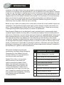
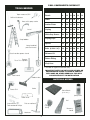
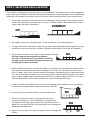
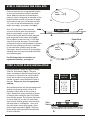
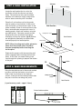
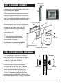
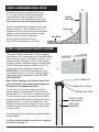
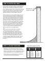
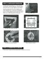
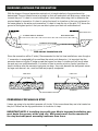
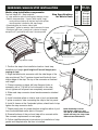
Installation Manual
Metric Series Residential Swimming Pool
IMPORTANT SAFETY INFORMATION
WARNING: DO NOT DIVE OR JUMP. IT IS NOT DESIGNED FOR DIVING OR
JUMPING. YOUR POOL IS APPROXIMATELY 4’ DEEP. IF YOU DIVE OR JUMP
INTO YOUR POOL YOU RUN THE RISK OF PERMANENT INJURY OR DEATH.
Enclosed in the liner box is the safety envelope. The safety stickers must be installed as per instructions. Failure
to properly install warning labels will void warranty. Alert all visitors and family of the risks associated with jumping
and/or diving and point out all warning labels supplied. Failure to mount these safety labels may subject you to
substantial liability in case of injury.
Your pool is designed for years of pleasurable, safe family fun. But when used incorrectly, a swimming pool can be
dangerous. To insure your pool is used safely you must observe the following safety precautions:
1. Do not dive, do not jump, no rough play, no running or pushing.
2. Do not walk on the top rail. It can be slippery and is not a walkway.
3. Be sure to install all safety labels provided with your pool according to the safety instructions.
4. Keep a 50’ safety rope with a flotation buoy with an outside diameter of 15” accessible in a prominent area
by your pool.
5. Post near all entrances to the pool area a list of telephone numbers for the following:
a. Local police
b. Local fire department
c. Local rescue unit
d. Local ambulance service
e. Local hospital
f. 911 emergency number, if available
6. Provide fencing or an enclosure which is independent of the house as a closure around the entire pool
area. The fencing must be made of durable material, a minimum of 4’ high from ground level and with
closures with self-latching locks to make the pool inaccessible to toddlers and uninvited guests. Make sure
the gate is always closed. Be sure to follow local building code requirements for load capacity and fencing
if using an aftermarket or homebuilt deck.
7. Check with your local town or municipality in regard to obtaining a building permit and/or an electrical
permit. The installer shall follow the regulations for set backs, barriers, devices and other conditions.
8. All electrical outlet connections should be a minimum of 5’ from the outside perimeter of the wall of the
pool. From 5’-10’ there should be either a fixed connection (outlet box) or twist lock connection with a
GFCI. Connect power cords to a 3-wire grounding-type outlet only.
9. Severe electrical shock could result if you install your pump or filter on a deck. They could fall into the
water causing severe shock or electrocution. Do not install on a deck or other surface at, above or slightly
below the top ledge of the pool, within 5 feet of pool water edge.
10. Do not sit, stand or climb on the pump and filter or any part of the pool structure. Components such as the
filtration system, pumps and heater must be positioned so as to prevent their being used as a means of
access to the pool by young children.
11. Never drink alcoholic beverages or use any intoxicants which could hinder your judgment and reflexes.
12. Never use the pool alone. All children must be supervised continuously.
13. Do not use pool if bottom is not clearly visible. At night, sufficient lighting must be available. It is the pool
owners’ sole responsibility to provide adequate lighting for the pool bottom, safety signs and walkways,
which exceeds minimum standards of the IES of North America.
14. Be sure that all toys, chairs and tables or similar objects that a young child could climb on be at least 4’
from the pool.
15. Do not use pool during electrical or rain storms.
16. See available Association of Spa and Pool Professionals (APSP) publications for more tips on pool safety.
INTRODUCTION
Installation of the Metric Series above ground pool is not extremely hard or confusing. The
installation of an average size aboveground pool (18’-33’ diameter) will usually require 2-3 people
to help set it up. The secret to installing a pool so that it will give you years of enjoyment is to take
the time to follow the step-by-step instructions. It is very important to follow the instructions in the
sequence laid out in this manual. Included in this manual is an assortment of tools and materials
which you will need for preparing the ground, checking the levelness and setting up the pool.
Failure to follow instructions exactly will void all warranties. Read all instructions for related
accessories such as pumps, filters, etc. prior to starting.
Before you start, check your packing list to confirm that you have the correct number of parts and
components. The manufacturer reserves the right to revise, change or modify construction of its
pools. See proceeding page for Metric Series Pool Components chart. If there are any missing
or damaged components, please contact your retailer for replacement.
Even though all Radiant pools are designed to meet or exceed industry recommended safety
standards, special attention must be paid to all installation procedures that the installer performs
and controls. Spend time to assure that the entire pool framework is perfectly level. Unlevel pools
place extreme pressures on the pool walls. An earth mound or pool cove must also be installed.
This keeps the pool liner from creeping out from under the pool wall. Be sure to follow these
instructions. Improperly installed pools can rupture, allowing thousands of gallons of water to rush
out causing extensive property damage and injury to anyone in its path. As with any major home
project, a homeowner is responsible for following all local laws, ordinances and codes. Electrical
grounding of swimming pool is required. National and local codes must be followed. A checklist is
provided below as a guide for these considerations.
With proper installation and care and
maintenance, this Metric Series Residential
Swimming Pool from Radiant Pools will
provide a lifetime of fun and relaxation for
you and your family and friends.
✓
HOMEOWNER CHECKLIST
Obtain building permit if required.
Local building and zoning requirements
Radiant Pools offers a, non-prorated,
lifetime warranty on the entire pool
against manufacturing defects. Walls
panels, and aluminum components are
warranteed against factory defects due
to faulty workmanship or defects due to
manufacturing for as long as you own your
pool. Compare our warranty with any other
pool manufactured. Engineering, innovation
and efficiency make the difference.
It’s simply brilliant.
Electrical and Grounding requirements
Proper Backfill and Drainage
Fencing requirements
Backwash (waste water) requirements
Check availability of utilities.
Call before you dig (www.digsafe.com)
simply brilliant.
1
POOL COMPONENTS CHECKLIST
TOOLS NEEDED
Component
Tape measure, 50ft.
18’ 21’ 24’ 27’ 30’ 33’
Panels
8
10
10
10
12
14
Rebar
8
10
10
10
12
14
Anchor Plates
8
10
10
10
12
14
Coping
8
8
10
10
12
14
White Cap Screws
50
50
50
50
100 100
Coping Clips
8
10
10
10
12
14
Splines
16
20
20
20
24
28
Bolts (3/8”x2 1/4”)*
16
20
20
20
24
28
Skimmer Kit
1
1
1
1
1
1
Return Fitting
1
1
1
1
1
1
Vinyl Liner
1
1
1
1
1
1
Soft bristle broom
Hose with spray nozzle
Level
Step Ladder
Long handled
pointed shovel
Short handle square shovel
Tamper,
10 or 12 in. Square
* included for inground installation only.
IMPORTANT NOTE: DO NOT ALLOW SPLINES OR
COMPRESSION SEAMS TO COME IN CONTACT
WITH SAND OR OTHER DEBRIS AS THIS WILL
CAUSE DIFFICULTY IN INSTALLATION
Pool trowel
Garden rake
MATERIALS NEEDED
Stake
Power Drill
Patio Blocks
(2”x8”x16”)
Spray Paint
Razor knife
2x4
Screwdrivers,
Flathead and Phillips
Pick or mattock
String
Hacksaw
2
Masonry
Sand
IMPORTANT: BEFORE YOU BEGIN
The selection and preparation of the pool site is your responsibility. The manufacturer can
only suggest the proper techniques, indicate the important considerations and emphasize the
precautions and cannot be held responsible for damages to your pool that may result from
failure to carefully follow all pool specifications.
All Radiant Pool components are engineered to provide a precise fit. It is very important to
handle all components with care. Prior to assembly, all pool components should be free of
sand, mud, dirt and debris of any kind.
Do not allow splines or compressions seams to come in contact with sand or other
debris as this will casue difficulty with installation. We recommend a small dust broom
or damp cloth be available in the event that any dirt or debris finds its way to these
parts.
3
STEP 1: SELECTING POOL LOCATION
The selection and preparation of the pool site is your responsibility. The manufacturer can only suggest the
proper techniques, indicate the important considerations and emphasize the precautions and cannot be held
responsible for damages to your pool that may result from failure to carefully follow all pool specifications.
1. The surface on which your pool will stand must be absolutely level and solid. This condition should
extend 1foot beyond the actual pool area all around. The best surface is bare solid earth free from
stones, roots and other sharp objects.
CORRECT
NO
Fill
2. Allow plenty of play area around the pool. Fit the location into your landscaping plans.
3. The pool site must be accessible to electrical and water supply and should allow for disposal of great
quantities of water when the pool is drained. All electric outlets within 10’ must be GFI protected.
5. Do not set up your pool in hilly areas or areas with poor drainage.
For Semi-Inground and Inground Installations:
The site of installation must accomodate an efficient
drainage system to minimize the impact of heavy rain
and high ground water conditions.
NO
4. When installing your pool on a solid level surface, it is imperative that you protect your pool and liner
from chemicals and other foreign matter contained in the surface. Do not install your pool on peat
moss, tar paper, roots, sticks, gravel or chemically treated or contaminated soil not approved for pool
use. Any or all of these surfaces can ruin your pool and liner and will void your warranty. To prevent
stones or other foreign material from damaging the liner it is recommended to build a 2” to 3” base of
clean washed masonry sand or other suitable base material inside the entire pool.
5. If ants or termites are prevalent in your area, have soil treated with insecticides and allow sufficient
time for them to dissipate before continuing with pool installation.
6. Do not set up your pool under trees or under overhead wires.
7. Do not set up your pool near any existing structure such as
your house, garage, etc., as this condition may compel diving
or jumping into your pool which could result in permanent injury or
death. You must check with your local municipality for all appropriate
ordinances and regulations.
8. Do not set up your pool on or near any septic system or underground
utilities.
4
NO
NO
STEP 2: PREPARING THE POOL SITE
Once you have chosen an appropriate location
for your pool based on the criteria specified
above, determine the pool circumference by
putting a stake in the ground at the center of the
location desired and with a line equal in length
to the radius of the pool (1/2 the pool size plus
12”), mark off the circumference with a sharp
object, lawn edger, spray paint, etc. (fig.A)
Pool
Radius + 12”
A.
After all of the sod has been removed,
you must make the pool area absolutely
level as measured by a transit or level.
Find the lowest spot within the pool area and
level the ground to that lowest spot. (fig.B)
Do not add dirt to the low areas. It is the high
areas that must be dug away. The perimeter
of the pool must be a solid foundation to prevent
the pool from settling into dirt that is loosened
by rain and water splashing over the side.
Once again, clean the area of all sharp objects,
including roots and rocks that could later effect
your swimming pool.
B.
Patio Block
Pool
Radius
For Site Preparation insstructions for
Inground installation, see page 12.
C.
STEP 3: PATIO BLOCK INSTALLATION
Once the ground is prepared, begin installing
2”x8”x16” patio blocks. (fig.C) The patio
blocks should be installed at the perimeter line
of the pool (1/2 the pool size from the center
stake) and at intervals corresponding to the
number of panels associated with the size of
the pool. Please see chart for appropriate
spacing.
Sink each patio block into the prepared ground
making sure that each block is level in all
directions (side to side as well as front to
back). Repeat this step around the perimeter
of the pool area making the tops of all blocks
level with the ground. Do not install the blocks
on loose sifted soil or sand. All patio blocks
must be flush with the ground, solid and level
with each other in all directions. Once all of
the patio blocks are installed, place a joiner
plate on each patio block. (fig.E) The joiner
plates will be used to provide a level platform
for wall installation.
Pool
Size
Patio Block
Intervals
Qty
Needed
18’
21’
24’
27’
30’
33’
6’ 10 5/8”
6’ 5 7/8”
7’ 5”
8’ 4 1/8”
7’ 9 1/8”
7’ 4 1/8”
8
10
10
10
12
14
Patio
Block
D.
5
Skimmer
STEP 4: WALL INSTALLATION
Return Fitting
Locate the wall section that is cut for the
installation of both the skimmer and return
fitting. The location for this panel should be
adjacent to the electrical supply and provide
ease of access once the pool is installed.
Place the 2 wall sections so that the panels
meet on center of a patio block. At the end of
each wall panel is a compression seam for the
spline assembly. Place an anchor plate on patio
block, centered under compression seams of
meeting panels. Attach wall sections using the
provided splines. Please be aware that each
compression seam should be flush before
attempting to insert the splines. (fig.G) Splines
are designed to slide freely into place when
inserted properly into leveled panels.
Wall Section
Compression Seam
Pool Exterior
Anchor Plate
NOTE: When inserting each spline, please be
aware that the outside spline should be
inserted completely before inserting the
inside spline.
E.
Patio Block
Duplicate this process with the remaining wall
panels stopping before installing the final wall
panel. At this time, you need to bring in the
sand through this opening to prepare the bottom
of the pool.
Spline
G.
STEP 5: SAND REQUIREMENTS
Bring the required amount of clean and washed
masonry sand into the interior of pool area
Refer to the chart below for the required
amount. Once the sand has been placed inside
the pool, install the remaining wall panel.
Compression
Seam
Pool Exterior
(1 yard masonry sand = appx 1.5 tons)
Pool
Size
Sand Amt
(cubic yds)
18’
21’
24’
27’
30’
33’
2
3
3.5
4.5
5.5
6.5
Dished bottom option
12" max.
6
Mounting Plate
STEP 6: SKIMMER ASSEMBLY
Gasket
Install rubber gasket on the mounting plate,
making sure the gasket straddles both sides of
the mounting plate. (fig.H)
I.
H.
Slide skimmer face through pre-cut skimmer
opening, keeping skimmer body on outside of
pool wall. Attach gray plastic mounting plate
tightly to skimmer face using panhead screws
into each side center holes as shown circled.
(fig.I)
Gray Plastic Skimmer
Mounting Plate w/gasket (1)
2” countersunk bolts (4)
Fasten assembly by inserting 2” countersunk
bolts through corner holes in mounting plate,
through pre-cut holes in pool wall and
through corner holes in plastic backup
plates securing with T-nuts.
Hand tighten only.
Finish securing backup plates with
4 sheet metal screws per diagram.
The skimmer faceplate is attached
after the liner is installed.
For Skimmer Assembly instructions for
Inground installation, see page 15.
Skimmer
Sheet metal
screws (4)
Pre-cut Skimmer
Mounting holes (4)
Plastic Backup Plates (2)
STEP 7: RETURN FITTING ASSSEMBLY
The return fitting is comprised of 3 pieces:
inlet fitting, SP 1091Z10 and back nut. (fig. J)
In geographic areas of deep winter ground
freezing, an inlet plate (#3185) is
recommended.
J.
Install the return fitting by threading the
SP 1091Z10 into the inlet fitting. Place the
assembly into the pre-cut hole, slide the inlet
plate over the exposed threads and then
thread the back nut onto the SP 1091Z10
fitting. All threaded connections should be
prepared using a combination of Teflon tape
and marine grade silicone. The return faceplate
is attached after the liner is installed.
SP 1091Z10
Inlet Fitting
Back Nut
Inlet Plate
7
STEP 8: PREPARING POOL COVE
K.
Using the masonry sand, build a pool cove
6” to 8” high inside the wall along the entire
circumference of the pool.(fig. K) This will
prevent the liner from creeping under the wall.
This step is not optional and must be done.
Spread the remaining sand equally across the
bottom of the pool. This will give you a 2” to 3”
sand base. After the cove and base are in place,
dampen, rake and tamp the entire pool area.
Make sure that no sand is allowed to
remain on the wall above the cove.
This could cause pinholes in your liner.
Interior
Pool Wall
Pool Cove
Pool Base
STEP 9: INSTALLING PLASTIC COPING
The plastic coping is attached by simply snapping
over the pool wall. Each coping joint should be offset
from a wall joint. (fig. L) You need to leave a 1” gap
between lengths of coping. Once all of the coping
has been placed, secure the coping to the pool wall
with the white cap screws provided. Using a 3/32”
drill bit, drill through the plastic coping and
EXTERIOR pool wall while pressing down firmly
on the coping on top of pool wall. Using a Phillips
screw driver, hand tighten each screw. DO NOT
OVERTIGHTEN.
Note: Plastic coping on the interior side of the
pool wall will be held in place by the weight of
the water on the beaded vinyl liner.
For the 18’ pool, the screw spacing should be
approximately 24” beginning with the first screw
approximately 2”-3” over from a compression seam.
For all other pool sizes, the screw spacing should
be approximately 29” beginning with the first screw
approximately 2”-3” over from a panel joint. The
beaded vinyl liner with the weight of the pool water
will draw coping into place and level on the interior
of the pool wall.
Install coping clips by snapping over gaps between
coping lengths.
For CP2 coping installation instructions for Inground
installation, see page 15.
8
Coping Clip
Wall Joint
L.
Pool
Exterior
PVC COPING CLIP
DURABLE PVC COPING
BEADED VINYL LINER
ACRYLIC COATED
ALUMINUM WALL
2" EPS FOAM
INSULATION
STEP 10: INSTALLING LINER
Clear all sticks and sharp objects from an area near
the pool that is as large as the pool itself. Remove
the liner from its carton and unfold and open the
IECERECEIVER
R DAEB
liner. Refold the liner so that it can easily be carried REVBEAD
to the pool and unfold from the outside of the pool.
RENIL LYNBEADED
IV DEDVINYL
AEB LINER
Check to make sure the sand in the pool is level
and that there are no sharp objects in the pool.
Place the liner into the pool while holding onto the
top of the wall section of the liner. Snap the bead
of the liner into the bead receiver around the entire
pool. Gently pull on the liner and use a soft bristle
broom to remove as many wrinkles as possible on
the bottom of the pool. Start filling the pool slowly
with water. Continue pulling gently and working the
liner with a broom as needed. Some wrinkling of
the liner may be evident and in no way affects the
structural strength of your pool. You can continue
to work out the wrinkles as needed by pulling
gently on the liner or by using a broom.
TIP: To help in removing stubborn wrinkles,
a shop vacuum may be used to suck the
air out from behind the liner.. Attach shop vac
to skimmer outlet and seal with duct tape. Seal
all other openings with duct tape as well. Turn on
vac and run till wrinkles are removed. Once the
wrinkles are gone, begin filling with water. After 6”
of water is in the pool, turn off and remove the
shop vac.
STEP 11: FILLING YOUR POOL
Water Gallonage per Pool Size
Whether you are filling the pool with your own
home water source or through a water-fill service,
please use the chart at right to determine the water
volume requirements for your particular size pool.
Please see your pool professional for instructions
on proper water testing and balancing.
9
Pool
Size
18’
21’
24’
27’
30’
33’
48” Pool Wall
(40” of water)
6335
8622
11,262
14,254
17,645
21,293
52” Pool Wall
(44” of water)
6963
9477
12,378
15,666
19,388
23,403
STEP 12: INSTALLING FACEPLATES
Once the water level reaches 2”-3” from the return
and skimmer, install the faceplates. Carefully locate
the screw holes in for each opening. Once located,
carefully puncture the liner with an icepick or nail.
Attach faceplate with 1” screws and hand tighten
evenly till snug. Using a razor knife, carefully trim the
liner out of the openings for the skimmer and return.
When done, install the eyeball into the return.
Locate screw holes.
Skimmer faceplate installed.
Trim liner from skimmer opening.
Return faceplate installed.
Trim liner from return opening.
STEP 13: CONNECTING PLUMBING
Please refer to pump and filter manufacturers’ installation instructions.
10
Metric Inground Installation Instructions
11
INGROUND: LEVELING THE EXCAVATION
With the shape of the pool excavation marked out, its height relative to the ground must be
determined. The pool should be set at a height so that rain and splash will drain away, rather than
towards the pool. It is best to use a building level, transit and a measuring stick to determine the
required depth of excavation. It is best to set up the transit in a location so that you can leave it in
the same place for the entire pool excavation. It is best to keep the top of the pool 2”-6” above the
ground at the highest point so that you are able to place your deck on undisturbed soil.
TRANSIT
MEASURING STICK
2" - 6" ABOVE HIGHEST GROUND
OUTLINE OF POOL
FLOOR OF EXCAVATION
SIDE VIEW OF EXCAVATION SITE
Since the excavation will be 2’ wider ( Recommended for the first time installations, even though a
1’ excavation is acceptable) all around than the actual pool dimension, it is important that the
excavator does not dig the 2’ ledge around the hopper too deep. A sturdier pool will result when
the pool rests on undisturbed earth. It is better to have to remove a inch or two by hand then to
have to build up after the excavator had gone too deep. Any voids beneath the wall panels cause
by large rock removal, etc., must be filled and properly compacted.
POOL WALL
POOL WALL
CUT AWAY
FILL IN
CORRECT
INCORRECT
UNDISTURBED EARTH
PREPARING FOR WALK-IN STEP
If steps are going to be installed, excavate a 6 foot by 10 foot area where they are to be located on
the pool. Please see the dig specifications for locations of steps.
IMPORTANT NOTE: if installing steps with your Metric Inground installation, you
must begin the process at the step site. Wall panels must first be mounted to
the step and wall panel assembly continues from there.
12
INGROUND: WALK-IN STEP INSTALLATION
Metric step installation components:
Pool wall height 52" / Step height 48"
• 4" step extension plate to close gap at bottom of step
• Radius step connector - 2 parts (both are 48" long):
- male portion attaches to the pool wall with splines
- female portion is bolted to the step flange
• Standard spline for interior side of pool
• Extended T spline for exterior side to connect A-frame
• Each pool will have 1 panel that is shorter in length,
except the 27' pool which will have 2 shorter panels
Step Specifications
for Metric Pools
Pool
Size
Step Type
(48” Height)
18’
21’
24’
27’
30’
33’
8’ Radius
8’ Straight
8’ Straight
8’ Straight
8’ Straight
8’ Straight
T-Spline
Male Stair Connector
Radius Wall Panel with
Compression Seam
Hex Bolt
Hex Nut
Female Stair Connector
Step Extension Plate
Stair Flange
1. Position the step in the installation location. Level step,
establish pool height (pool height will be wall height plus
coping on top).
2. Align the female stair connector with the side flange of the
step as pictured. The ‘C’ receiver toward and flush with front
interior edge of the step. The top of the connector at finished
wall height
3. Clamp connector in place, drill step flange at holes in
connector with a 7/16 drill bit, bolt connector to the step,
do not tighten until all panels are completely connected.
4. Slide male step connector down female connector attached
to step.
5. Install standard spline on interior side of pool and extended
T spline on exterior side, connecting the step to the first panel.
6. Install A-frames at the 2 extended splines, check level of step,
tighten the step connector bolts.
7. Check panel joints for proper location-using the radius of pool
from the established center point of the pool.
8. Encase the base of the pool and step with a concrete collar.
See concrete requirements on next page.
9. Follow step Manufacturer’s instructions for installation of step
gasket and faceplate after the liner is installed.
13
Note: Drawings are for
illustrative purposes and
are not to scale. Attachment
detail will vary for steps from
different manufacturers.
INGROUND: ANCHORS PLATES AND WALL CLIPS
Anchor Plates
Wall anchors are located at each compression
seam. With a high speed metal drill bit, drill
two 7/16” holes on each side of the compression
seam in each wall anchor as shown. Insert
a provided nut and bolt through each drilled
hole as illustrated, with the nut on the outside
of the pool (fig.1). Drive rebar through one bottom
hole to secure in proper. Duplicate this
process with the remaining anchor plates.
Pool Exterior
2" Wall Clip
2" Wall Clips
Tek Screw
Pool Exterior
Wall Clip Detail
Wall Clips for Installation of CP2 or
Extrusion Coping
Slide clips, evenly spaced, over radius wall
panels to attach concrete receptor coping.
Clips are to be secured in place with tek
screws, through exterior pool wall.
Pool Interior
Hex Bolts
Wall Anchor
14
INGROUND: SKIMMER ASSEMBLY
Gasket
Mounting Plate
Install rubber gasket on the
mounting plate,
making sure the gasket straddles
both sides of the mounting plate.
(fig.H)
Countersunk Bolts (4)
Plastic Skimmer
Mounting Plate (1)
with gasket (1)
H.
Slide skimmer face through
pre-cut skimmer opening,
keeping skimmer body on
outside of pool wall. Fasten
assembly by inserting 2”
countersunk bolts through
corner holes in mounting plate,
through pre-cut holes in pool
wall and through skimmer
mounting brackets, securing
with hex nuts. Tighten nuts to
a snug fit.
Nuts (4)
Do not over tighten as this will
damage the mounting plate.
Skimmer Mounting
Brackets (2)
Install skimmer support.
It is recommended that
2” PVC pipe be cut to size,
depending on installation. Utilizing
a 2” male adapter, attach support
to bottom of skimmer as shown.
Extension Collars (fig.I) are used
to raise the top of the skimmer to
the height of decking. The number
of extension collars needed is
determined by the variable decking height.
Skimmer
2" Male Adapter
Skimmer
Support
I.
The skimmer faceplate is attached after the liner is installed.
Tek screw
INGROUND: CP2 COPING INSTALL
2" Wall Clip
Place pre-bent coping length on top of the pool wall. Secure it with Tek screws at the previously installed 2” wall
clips. The next length is placed adjacent to the end of the
first length, continuing around the pool. It is not necessary
to leave spacing as with the standard white coping. If you
are installing a walk-in step, start at the step and continue
around the pool, cutting the last length to fit. Install coping
clips to cover the ends of the lengths.
15
Tek screw
Pool Interior
CONCRETE COLLAR GUIDE
Check with local building codes before installing your Radiant Metric pool inground. If the pool
is to be installed in geographic areas with winter ground freezing, Radiant Pools recommends
a 6” to 8” concrete collar around the entire pool (fig.1).
If you are installing a walk-in step, Radiant Pools REQUIRES that a concrete collar be poured
around the entire pool (fig.2). Add 2.5 yards of concrete to the ‘estimating concrete requirements’
for the concrete around the step and A-frames.
Concrete Collar
fig.1
Pool
Interior
12"
Drift Pin
8"
Undistrubed Earth
Concrete Collar
at Step and
A-Frame
Location
fig.2
Step
Pool
Interior
2'
Drift Pin
A-Frame
8"
Drift Pin
Concrete
Undistrubed Earth
Estimating Concrete Requirements:
These are minimum estimating figures. It is recommended that estimates be on the high end
as the excess can be poured around A-Frame and step. Combine both figures below for
total yards of concrete required.
Collar: Pool Perimeter (ft.) x .02 = Yards required.
16
RADIANT POOLS METRIC SERIES RESIDENTIAL SWIMMING POOL
NON-PRORATED LIFETIME LIMITED WARRANTY
There are no warranties that extend beyond the description on the face hereof. This Warranty, offered by Trojan
Leisure Products LLC, dba Radiant Pools, of Albany, NY, herein called the “Manufacturer”, is effective upon completion of
payment by purchaser. Manufacturer warrants its manufactured swimming pool components against manufacturing defects.
These components include wall panels, panel connectors, top and bottom channels, all aluminum bracing components,
splines and aluminum nuts and bolts only. This Warranty does not extend to equipment and other accessories not
manufactured by Trojan Leisure Products, LLC. Manufacturer’s Warranty performance is subject to the following terms
and conditions:
Transpor tation: Purchaser is responsible for all
transportation charges incurred for any item returned for
repair or replacement.
Costs: Purchaser is responsible for the cost of installation
or reinstallation of any item repaired or replaced under this
Warranty.
Notification and Delivery: Purchaser must notify
Manufacturer of any defect, and the defective item must
be delivered to Manufacturer, transportation costs prepaid
to: 440 North Pearl Street, Albany, NY 12207. Manufacturer
will effect repair or replacement within thirty (30) days of
receipt, unless purchaser is otherwise notified.
Warning: For maximum use and enjoyment, your Radiant
Pool must be kept filled with water at all times.
Manufacturer shall not be responsible for any irregularities
or imperfections that may result when water is removed
from your Radiant Pools vinyl liner swimming pool.
Winter Damage Provision for Metric Series Pools Only:
The Manufacturer will replace or repair any of its
manufactured swimming pool components, as set forth
above, damaged due to the ill effects of ice or snow directly
on pool only. Any damage resulting from impact of any
objects such as tree limbs or vehicles are excluded.
Purchaser must notify Manufacturer of any winter damage
to receive a winter damage claim form. Manufacturer will
effect repair or replacement within thirty (30) days of receipt
and final processing of winter damage claim form, unless
purchaser is otherwise notified.
Registration of Warranty: After reading your Warranty,
please complete and return the enclosed registration card
within sixty (60) days after delivery of your Radiant Pool,
or within thirty (30) days after installation of your Radiant
Pool if installation is completed within a period less than
sixty (60) days after deliver y. UNLESS OUR
REGISTRATION CARD IS RETURNED AS DIRECTED,
THIS WARRANTY IS NULL AND VOID.
Transfer of Warranty: The provisions of this Warranty
are personal to the original purchaser of the Radiant Pool.
This Warranty is 100% transferable from the original
purchaser. The new owner must obtain a warranty transfer
card from the original purchaser to be submitted to
Manufacturer within sixty (60) days of purchase to maintain
warranty.
ANY IMPLIED WARRANTIES, INCLUDING BUT NOT LIMITED TO, THE IMPLIED WARRANTIES OF MERCHANTIBILITY AND FITNESS FOR A PARTICULAR PURPOSE,
ARE HEREBY LIMITED TO THE DURATION AND SCOPE OF THIS WRITTEN WARRANTY. SOME STATES DO NOT ALLOW LIMITATIONS ON HOW LONG AN IMPLIED
WARRANTY LASTS, SO THE ABOVE LIMITATION MAY NOT APPLY TO YOU. UNDER NO CIRCUMSTANCES SHALL TROJAN LEISURE PRODUCTS, LLC BE LIABLE FOR
SPECIAL, INCIDENTAL OR CONSEQUENTIAL DAMAGES, INCLUDING, BUT NOT LIMITED TO, ANY DAMAGES FOR LOSS OF USE OF POOL, INJURY TO, OR DEATH OF,
ANY PERSON, OR DAMAGE TO PROPERTY, AND ANY CLAIMS THEREFORE ARE HEREBY SPECIFICALLY DISCLAIMED AND EXCLUDED. SOME STATES DO NOT ALLOW
THE EXCLUSION OF SPECIAL, INCIDENTAL OR CONSEQUENTIAL DAMAGES. THEREFORE, THE ABOVE LIMITATION MAY NOT APPLY TO YOU.
Trojan Leisure Products, LLC. 440 North Pearl Street, Albany, NY 12207
518-434-4161 fax 518-432-6554
✁
Owner Name ____________________________ Serial No. ________________________________________
Address ____________________________ City, State, Zip ________________________________________
Pool Size _________________________ Purchased From ________________________________________
Installed By:
Dealer
Private Installer
Owner
Date of Installation ____________________________
IMPORTANT: PLEASE READ AND SIGN: I have received and reviewed the Pool Owner’s Operating and Safety Information
package which includes: Safety Guide, Consumer Care Manual, Liner Warranty, “No Diving” stickers/instructions, “No Diving Sign, Pool Owner
Warning.
________________________________________________________________________________________
Owner’s Signature
Date
PLACE
POSTAGE
HERE
div. Trojan Leisure Products, LLC
440 North Pearl Street
Albany, NY 12207