1
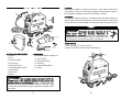
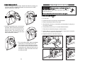
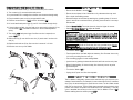
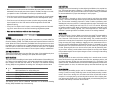
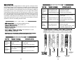
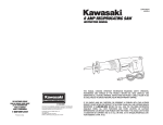
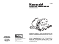
COMPONENT #840641 80 AMP WIRE FEED ARC WELDER INSTRUCTION MANUAL THIS MANUAL CONTAINS IMPORTANT INFORMATION REGARDING SAFETY, OPERATION, MAINTENANCE AND STORAGE OF THIS PRODUCT. BEFORE USE, READ CAREFULLY AND UNDERSTAND ALL CAUTIONS, WARNINGS, INSTRUCTIONS AND PRODUCT LABELS. FAILURE TO DO SO COULD RESULT IN SERIOUS PERSONAL INJURY AND/OR PROPERTY DAMAGE. FOR CUSTOMER SERVICE POUR LE SERVICE APRÉS VENTE OU DU CONSOMMATEUR PARA EL SERVICIO PARA EL CONSUMIDOR 1-800-590-3723 Printed in China 87-1904-60957 KAWASAKI™ IS A TRADEMARK LICENSED BY KAWASAKI™ MOTORS CORP., U.S.A., WHICH DOES NOT MANUFACTURE OR DISTRIBUTE THIS PRODUCT. CONSUMER INQUIRES SHOULD BE DIRECTED TO: ©COPYRIGHT 2007 ALLTRADE TOOLS, LLC. 1431 VIA PLATA LONG BEACH, CA 90810-1462 USA 8400641 – 80 Amp Wire Feed Arc Welder_Rev. 6/21/07 IF YOU SHOULD HAVE ANY QUESTIONS OR EXPERIENCE A PROBLEM WITH YOUR ALLTRADE PRODUCT, DO NOT RETURN THIS PRODUCT TO THE STORE. PLEASE CALL OUR CUSTOMER SERVICE DEPARTMENT AT 1-800-590-3723. BEFORE YOU CALL, HAVE THE FOLLOWING INFORMATION AVAILABLE: MODEL No., DATE PURCHASED AND STORE LOCATION. AN ALLTRADE REPRESENTATIVE CAN RESOLVE YOUR PROBLEM OVER THE PHONE. IF YOU WOULD LIKE TO MAKE A SUGGESTION OR COMMENT, GIVE US A CALL OR EMAIL US AT: [email protected]. YOUR FEEDBACK IS VITAL TO US. TABLE OF CONTENTS CONGRATULATIONS! . . . . . . . . . . . . . . . . . . . . . . . . . . . . . . . . . . . . . . . . . 2 INTENDED USE . . . . . . . . . . . . . . . . . . . . . . . . . . . . . . . . . . . . . . . . . . . . . . 2 SECTION ONE GENERAL SAFETY RULES . . . . . . . . . . . . . . . . . . . . . . . . . . . . . . . . . . 3 RECOGNIZE SAFETY SYMBOLS, WORDS AND LABELS . . . . . . . . 2-3 IMPORTANT SAFEGUARDS . . . . . . . . . . . . . . . . . . . . . . . . . . . . . . 3 WORK AREA . . . . . . . . . . . . . . . . . . . . . . . . . . . . . . . . . . . . . . . . . . 4 ELECTRICAL SAFETY . . . . . . . . . . . . . . . . . . . . . . . . . . . . . . . . . . . 4 PERSONAL SAFETY . . . . . . . . . . . . . . . . . . . . . . . . . . . . . . . . . . . . 5 TOOL USE AND CARE . . . . . . . . . . . . . . . . . . . . . . . . . . . . . . . . . . 6 SERVICE . . . . . . . . . . . . . . . . . . . . . . . . . . . . . . . . . . . . . . . . . . . . . 6 SECTION TWO SPECIFIC SAFETY RULES AND/OR SYMBOLS . . . . . . . . . . . . . . . . . . . 7 IMPORTANT SAFETY RULES FOR USING ARC WELDERS . . . . . . . 7-8 SYMBOLS . . . . . . . . . . . . . . . . . . . . . . . . . . . . . . . . . . . . . . . . . . . . 8 SECTION THREE FUNCTIONAL DESCRIPTION . . . . . . . . . . . . . . . . . . . . . . . . . . . . . . . . . 9 ASSEMBLY . . . . . . . . . . . . . . . . . . . . . . . . . . . . . . . . . . . . . . . . . . . . . . 10-13 ATTACHING THE HANDLE . . . . . . . . . . . . . . . . . . . . . . . . . . . . . . . 10 ASSEMBLE WELDING HELMET . . . . . . . . . . . . . . . . . . . . . . . . . . . 11 LOAD / REPLACE FLUX CORE WELDING WIRE . . . . . . . . . . . . . . . 12-13 OPERATING THE ARC WELDER . . . . . . . . . . . . . . . . . . . . . . . . . . . . . . 14-19 DUTY CYCLE AND THERMAL OVERLOAD OPERATION . . . . . . . . . 14 WELDING TIPS . . . . . . . . . . . . . . . . . . . . . . . . . . . . . . . . . . . . . . . . 15 WELDING GUIDELINES . . . . . . . . . . . . . . . . . . . . . . . . . . . . . . . . . 15-17 ADDITIONAL SAFETY STANDARDS . . . . . . . . . . . . . . . . . . . . . . . . 17 TROUBLESHOOTING WELDS . . . . . . . . . . . . . . . . . . . . . . . . . . . . . 17-18 TROUBLESHOOTING WELDER . . . . . . . . . . . . . . . . . . . . . . . . . . . . 19 S EC T I O N F O U R MAINTENANCE AND CLEANING . . . . . . . . . . . . . . . . . . . . . . . . . . . . . . 20 ACCESSORIES . . . . . . . . . . . . . . . . . . . . . . . . . . . . . . . . . . . . . . . . . . . 20 SPECIFICATIONS . . . . . . . . . . . . . . . . . . . . . . . . . . . . . . . . . . . . . . . . . . 21 OTHER CONSUMER DO-IT-YOURSELF (DIY) TOOLS . . . . . . . . . . . . . . 21 SECTION FIVE 3 YEAR LIMITED WARRANTY . . . . . . . . . . . . . . . . . . . . . . . . . . . . . . . . 21-24 1 CONGRATULATIONS! Thanks for choosing this product. At Alltrade, our aim is to provide you with quality products at an affordable price, and we want you to be totally satisfied with your product and our Customer Service. If any help and advice is needed, please contact us at 1-800-590-3723. Properly cared for, this tool will give you many years of satisfaction. INTENDED USE This tool is intended for consumer use only. This tool is not designed for professional use. The power cord should only be used in approved electrical outlets as described in this manual. Failure to use the proper power cords and/or extension cords may result in fire or possible damage to the welder. GENERAL SAFETY RULES READ AND UNDERSTAND ALL INSTRUCTIONS. Failure to follow all instructions in this manual may result severe electrical shock, fire and/or serious personal injury or death. RECOGNIZE SAFETY SYMBOLS, WORDS AND LABELS The safety instructions provided in this manual are not intended to cover all possible conditions and practices that may occur when operating, maintaining and cleaning power tools. Always use common sense and pay particular attention to all the DANGER, WARNING, CAUTION and NOTE statements of this manual. This is the safety alert symbol. It is used to alert you to potential personal injury hazards. Obey all safety messages that follow this symbol to avoid possible injury or death. DANGER indicates an imminently hazardous situation which, if not avoided, will result in death or serious injury. WARNING indicates a potentially hazardous situation which, if not avoided, could result in death or serious injury. 2 CAUTION indicates a potentially hazardous situation which, if not avoided, may result in minor or moderate injury. WORK AREA CAUTION used without the safety alert symbol indicates a potentially hazardous situation which, if not avoided, may result in property damage. Ensure the work area is clean of debris and other foreign material that may ignite or explode upon contact with welding sparks or slag. NOTE provides additional information that is useful for proper use and maintenance of this tool. If a NOTE is indicated make sure it is fully understood. IMPORTANT SAFEGUARDS Read and understand all instructions before attempting to use the Arc We l d e r. Failure to follow and adhere to all safety precautions may lead to serious personal injury and/or death. DO NOT immerse any part of this equipment in water. Should the Arc Welder or attachments become wet for any reason, DO NOT use until completely dry. Using the Arc Welder when it is damp could lead to severe burns and/or DEATH from electric shock. DO NOT use the Arc W e l d e r i n c o n f i n e d s p a c e s w h e r e i n h a l a tion of fumes is possible. Use only in well ventilated areas. Breathing the fumes can lead to serious health problems such as bronchitis, pneumonia, or emphysema. Additional severe health risks include ulcers, intestinal inflammation, reproductive organ damage, kidney damage, heart disease, and early onset of Parkinson’s disease. Keep your head away from the fumes at all times. If you are at risk of breathing the fumes, wear an appropriate respirator. People with electronic devices, such as pacemakers, should consult their physician(s) before using this product. Operation of electrical equipment in close proximity to a heart pacemak er could cause failure or interference of the pacemaker. WARNING: Handling the power cord on this product may expose you to lead, a chemical known to the State of California to cause cancer and birth defects or other reproductive harm. Wash hands after handling. Keep the work area well lit at all times. Cluttered work benches and dark work areas may be prone to accidents resulting in serious injury. Keep the work area adequately ventilated. Breathing the fumes can lead to serious health problems such as bronchitis, pneumonia, or emphysema. Additional severe health risks include ulcers, intestinal inflammation, reproductive organ damage, kidney damage, heart disease, and early onset of Parkinson’s disease. Keep your head away from the fumes at all times. If you are at risk of breathing the fumes, wear an appropriate respirator. DO NOT operate the Arc W e l d e r i s a r e a s c o n t a i n i n g f l a m m a b l e liquids, gases, or dust. The welder creates sparks and extremely hot metal droplets or “slag” which can ignite the flammable liquids, gases, or dust resulting in severe burns and/or death. Keep bystanders, children, and visitors safely away from the Arc We l d e r d u r ing operation. All persons in the work area MUST wear protective welding gear, especially properly filtered goggles of welding helmets to prevent permanent, serious injury to the eyes or blindness. ELECTRICAL SAFETY Do not abuse the power cord or use a damaged power cord. NEVER use the power cord to carr y o r p u l l t h e e q u i p m e n t . N e v e r use the power cord to disconnect the plug from a power outlet. ALWAYS keep power cords away from heat, oil, sharp or jagged edges, or moving parts. REPLACE DAMAG ED POWER CORDS IMMEDIATELY. Damaged power cords increase the risk of severe electrical shock or burns resulting in serious injury and/or death. Always make sure the work piece is properly grounded and secured before attempting any welding operation. SAVE THESE INSTRUCTIONS FOR FUTURE REFERENCE. 3 4 PERSONAL SAFETY TOOL USE AND CARE Always remain alert. Be aware of your surroundings while using the Arc We l d e r. Do not use the Arc Welder while under the influence of prescription medication or alcohol. Using prescription medication or alcohol can affect your senses and slow your reaction time resulting in a serious personal injury or even death. Do not use the arc welder if the power switch does not turn “on” or “off!” Any equipment that cannot be controlled with the power switch is dangerous and should be repaired or replaced immediately. Before use, inspect the Arc Welder for damaged or defective parts. DO NOT use the Arc W e l d e r i f a n y p o r t i o n o r a c c e s s o r y i s d a m a g e d o r d e f e c t i v e . Carefully inspect the Welder and all the accessories for damage. Check for breakage of parts, damage to guards and switches, misalignment and/or seizure of moving parts that could affect the Welder’s operation. Ensure the Welder will operate properly and perform its intended function. If there should be damaged or defective parts, call A l l t r a d e ’s Customer Ser vice Department at 1-800-590-3723. DO NOT ATTEMPT to repair the Arc Welder yourself. Only trained technicians should repair this tool. DO NOT use the Arc Welder if the “ON/OFF” does not function properly. Always use ANSI compliant safety equipment. • Always wear eye and ear protection. • Use impact resistant safety goggles. • Wear non-skid safety shoes. • Always wear an approved welding helmet with the proper filters for the type of welding you are doing. • Always wear leather welding gloves and flame resistant clothing with long sleeves. Dress Properly • Do not wear loose clothing, jewelry, unrestrained long hair, or any other attire that may become caught in moving parts of the equipment. • Always wear ANSI compliant, protective, electrically nonconductive welding gear including protective clothing, leather welding gloves, welding helmet, and insulated footwear. 5 Store this equipment properly when not in use and keep out of reach of chil dren and untrained persons. This equipment is extremely dangerous in the hands of untrained users. Do not attempt to use this equipment at a current setting or duty cycle that exceeds those specified by the manufacturer. This Arc Welder is engineered to be operated at the specifications shown on the attached labeling. Deviations from these specifications could lead to damage to the equipment and/or serious injury or death to the operator. Always disconnect the power cord from the power source before making any adjustments, changing accessories, or storing the arc welder. Use clamps (not included) or other practical ways to secure the workpiece to a stable platform. Ensure the work piece is properly grounded before beginning any welding operations. Before use, check for damaged parts and examine all mounting bolts and other moving parts before using the equipment. Check the power cord for breaks and other damage and replace if necessary. Make sure the equipment is clean, dry, and free from oily substances. Do not used damaged equipment. DO NOT attempt to repair the Arc We l d e r. Only a qualified technician should make repairs to this tool. Do not force this equipment. ALWAYS use the correct equipment for the application being worked on. The correct equipment will do the job better and safer at the rate for which it was designed. SERVICE Use only authorized replacement parts for the Arc We l d e r. ONLY qualified repair technicians using authorized replacement parts must perform equipment service. Service or maintenance by unqualified personnel could result in considerable risk of personal injury. Use of unauthorized parts or failure to follow maintenance instructions may create a risk of injur y and/or death from electrical shock. 6 SPECIFIC SAFETY RULES AND/OR SYMBOLS Hold tool by insulated gripping surfaces when perform ing an operation where the cutting tool may contact hidden wiring or it’s own cord. Contact with a “live” wire will also make exposed metal parts of the tool “live” and shock the operator. Make sure the contents of closed containers are known and steps are made to properly ventilate or flush the contents to prevent possible explosions that could result in fire, serious burns and injur y and/or even death. Always keep power cords and welding cables away from your body at all times. IMPORTANT SAFETY RULES FOR USING ARC WELDERS Always uncoil the welding cable before use. Coiled cables may overheat. Never touch the work piece immediately after welding. Allow the metal to cool before handling in order to prevent serious injury. Never leave the Arc Welder running unattended. Always shut the equipment off before leaving the area. Trim any excess welding wire protruding from the torch before storage. When welding above your head, ALWAYS wear ear plugs to prevent sparks or hot metal drops from falling into the ear canal. Maintain ALL labels and nameplates on the Arc We l d e r. These carry important information. Should they become unreadable, contact Alltrade for replacements. Do not overreach or reach across operating equipment. Maintain proper footing and balance at all times. Do not turn on the “ON/OFF” switch until you are prepared to begin work. NEVER look at the arc welder flame without approved eye pro tection. Arc welding operations produce intense light, heat, and ultraviolet (UV) radiation. Always wear a welders helmet or goggles with the proper filtration when performing arc welding operations. Failure to use properly filtered goggles or helmet could cause permanent severe damage to your eyes or even cause blindness. The UV radiation will burn your skin and has been known to cause certain types of skin cancer. BE AWARE that arc welding produces sparks and drops of HOT metal. These sparks and hot metal can cause severe burns. Keep the work area clear of combustible materials. The sparks and hot drops of metal can cause certain materials to ignite or even explode. Some metals have coatings that produce extremely toxic fumes when heated. When working with metals containing beryllium, zinc, mercury, or metals that use cadmium or galvanize plating, remove the coating before welding. Even after the coating has been removed, work in a well ventilated area and DO NOT inhale the welding fumes. Always keep a fire extinguisher nearby when the Arc We l d e r i s in use. Sparks and/or hot drops of metal discharged during the welding operation can cause fires. Keep rags, paper, and other combustible chemicals away from welding operations at all times. ALWAYS ground the work piece first. To do this, clamp the grounding clamp to the work piece before you begin welding. NEVER let any part of your body touch the grounded work piece and the flux core wire at the same time. This could cause severe electrical shock resulting in severe injury or even death. 7 SYMBOLS IMPORTANT: Some of the following symbols may be used on your tool. Please study them and learn their meaning. Proper interpretation of these symbols will allow you to operate the tool better and safer. SYMBOL V A Hz W Kg min s NAME Volts Amperes Hertz Watt Kilograms Alternating Current Direct Current Alternating or Direct Current Earthing Terminal Minutes Seconds Diameter .../min No load speed Revolutions per Minute 1,2,3, … Ring Selector Settings EXPLANATION Voltage (Potential) Current Frequency (Cycles per Second) Power Weight Type of Current Type of Current Type of Current Grounding Terminal Time Time Size of Drill Bits, Grinding Wheels, etc. No-load Rotational Speed Revolutions, Surface Speed, Strokes, etc. per Minute Speed, Torque or Position Settings FUNCTIONAL DESCRIPTION LOCATION Position the Arc Welder on a secure level surface in a dry location where there is free circulation of clean air. Ensure all air passages are clean and free of obstructions. Blocked air passages can cause the Arc Welder to overheat. 1 2 3 5 4 UNPACKING All welding accessories (except for the welding helmet and leather gloves) are stored inside the wire feed compartment on the top of the welder. Lift and remove the wire feed cover to find the handle, work clamp, grounding cable, and wire spool. 6 15 ASSEMBLY 8 7 14 10 Disconnect the power plug from the AC p o w e r s o u r c e b e f o r e a n y a s s e m b l y, a d j u s t m e n t s , o r adding/removing accessories. Following this preventative step reduces the risk of the Arc Welder coming on accidentally and the risk of damage to the workpiece and injury to the operator. ATTACH HANDLE: 1. Place the handle (1) on top of the cover. 9 11 13 2. Secure the handle, using the screws and washers (2). 12 1 CONTROLS AND COMPONENTS: 1. Welder 2. Torch 3. Overload Indicator 4. Power Switch 5. Wire Speed Control 6. Amperage Selection Switch 7. Ground Cable 8. Power Cord 9. Helmet ACCESSORIES: 10. Wire Reel Washer and Wing Nut 11. Flux Core Wire 12. Wire Brush/Hammer 13. Contact Tip 14. Leather Welding Gloves 15. Wrench 2 2 This arc welder requires a dedicated 120V/60 Hz 30 AMP circuit at “Max” amperage setting or 20 Amp circuit at “Min” amperage setting to function properly. Do not run other lights, appliances, or tools on this circuit while the Arc Welder is in operation. Failure to comply with this CAUTION will result in tripped circuit breakers and/or blown fuses. 9 10 ASSEMBLE WELDING HELMET: 1. Position the headgear inside the helmet. Assemble the helmet by inserting the stud screw through the headgear and helmet into the tension nut. DO NOT tighten the tension nut at this time. LOAD / REPLACE FLUX CORE WELDING WIRE Ensure the welder is “off” before attempt ing to load the flux-core wire. Do not turn the welder “ o n ” until instructed. Failure to follow these instructions could result in serious personal injury. Do not touch anything with the torch head as it may ignite. LOADING THE FLUX-CORE WIRE 1. Ensure the welder is “ O F F. ” 2. Lift the cover. 3. Unscrew the wing nut by turning it counterclockwise. 4. Remove the empty wire reel from the shaft. 5. Secure the full wire reel (1) to the shaft (2) with the washer (3) wing nut (4) by turning it clockwise. 2. Position the adjustment arms on both sides of the helmet. Place the small pins through the helmet and into one of the small holes on the adjustment arms. This controls the fit of the helmet when lowered over the face and can be easily repositioned if necessary. 6. Unwind the flux-core wire (5) in a counterclockwise direction. 7. Press down on the tension spring (6) to remove tension. 8. Guide at least 12” of wire into the torch sheath. If the wire end is crimped or bent, cut it off and remove any visible burrs. 9. Replace the tension on the tension spring (6). 1 2 3. Try on the welding helmet. Adjust the headgear ratchet band to a comfortable position and lower the helmet. If the helmet is too far away or too close to the face, use a different hole in the adjustment arm. Adjust the tension nuts so the helmet can easily be lowered over the face by nodding the head. 11 3 5 4 A. B. C. D. BRINGING WELDING WIRE THROUGH THE TORCH HEAD 10. Turn the torch handle nozzle (7) counterclockwise and pull to remove. OPERATING THE ARC WELDER • Ensure the Arc Welder is turned “ O F F. ” 11. Turn contact tip (8) counterclockwise and remove. 12. Lay torch sheath out in a straight line so the flux-core wire moves through easily. 13. Plug the welder’s power cord into an approved AC outlet. 14. Press the current switch to “ M A X ” and turn the welder “ O N . ” 15. Lift torch handle and press trigger (9) until 2" of wire feeds through the tip. 16. If the wire does not feed, view wire feed unit to ensure wire is being fed. If not, turn the welder “ O F F ” and add more tension to the wire feed adjustment spring. 17. Turn welder “ O N ” and press trigger. One flux-core wire is exposed, turn welder “ O F F. ” 18. Slide contact tip (8) over the flux-core wire (10) and screw it into the torch end (11). • Ensure the work piece is free of chemicals or oily substances that may catch fire or impair the welding process. • Ground the object to be worked by attaching the grounding clamp. If the work piece is secured to a metal work bench, grounding the work bench is an acceptable alternate. • Set the Current Switch. The thicker the work piece, the higher the current. • Set the Wire Speed Control to 5. Adjust as needed. Plug in the power cord to an approved AC outlet. If an extension cord is used, refer to the manufacturer’s instructions to ensure it is heavy enough to handle the load. If the extension cord is too light, it may become overheated and ignite. 19. Replace nozzle and cut off any flux-core wire in excess of a 1/4 inch. Hold the Torch away from any grounded object. Contact with a grounded object may cause the torch to inadvertently ignite. 20.Close the cover on top of the welder. • Turn the Arc Welder “ O N . ” • Test the speed of the wire feed. Adjust as necessary. Cut off excess wire so only 1/4 inch is protruding from the torch tip. 2" 7 • Put on welding goggles or lower welding helmet. 8 • Ignite the arc by passing the electrode wire back and forth over the work piece. 9 • When finished welding, lift the torch away from the work piece or any other grounded objects. 10 • Turn the Arc Welder “ O F F. ” 8 1/4" • Unplug the AC power cord from the receptacle. DUTY CYCLE AND THERMAL OVERLOAD OPERATION 8 This Arc Welder is designed to operate at the maximum duty cycle, which is a percentage of actual weld time. For example, for a ten minute interval at 10% maximum duty cycle, the actual welding time would be one minute. The Arc Welder should then cool for nine minutes. The Arc Welder has an automatic thermal switch, which protects the internal components and accessories from overheating. If the duty cycle is exceeded the red lamp on the front of the Arc Welder will turn “ O N . ” Resume welding when the red lamp turns “ O F F. ” 11 13 14 WELDING TIPS • Make sure you move the torch across the weld at the proper speed. You want the weld metal to flow smoothly onto the work piece. If the bead is too high or too wide, your speed is too slow. If the bead is too narrow, your speed is too fast. • If the flux-core wire is burning up before leaving the contact tip, the wire speed is too slow. More tension should be added to the wire feed adjustment spring. • If the flux-core wire is leaving the contact tip before being completely melted, the wire speed is too fast. Less tension should be applied to the wire feed adjustment spring. • If the joint is not filled on the first pass, continue making passes until the welding joint is secure. Be sure to remove all remaining slag between passes. • Never use an electric arc welder to thaw frozen pipes. WELDING GUIDELINES GENERAL The KAWASAKI™ 90 Amp Wire Feed Welder incorporates a process called Flux Cored Arc Welding (FCAW). The FCAW process uses a special tubular wire with flux inside. When the current produced by the Welder flows through the circuit to the to the welding wire, an electrical arc is created between the wire and the work piece. Heat from the arc melts both the welding wire and the work piece. The liquefied metal then flows into the molten crater on the work piece creating a welded bond. ARC WELDING BASICS There are five general basics that can affect the output of the welded work piece: wire selection, heat setting, weld angle, wire speed, and travel speed. WIRE SELECTION The correct choice of welding wire can impact the effectiveness of the welding project. Factors such as welding position, work piece material type, thickness, and surface condition can affect the end results of the project. The American Welding Society (AWS) has set guidelines for welding wire. An example is shown below. E-70T-GS E7 0 T -GS AWG classification for self-shielding wire Weld Strength, times 10,000 lbs per square inch Welding Positions: 0 = Flat, 1 = All other positions Tubular Flux-core Wire Flux Type The Internet can be used for additional information on the American Welding Society (AWS) Standards: http://www.aws.org/ HEAT SETTING Obtaining the correct heat setting involves adjusting the Welder to the required setting. The proper heat setting is based on (1) diameter and type of welding wire, (2) position of the weld, and (3) the thickness of the work piece. Labeling on the Welder list recommendations for proper heat settings for most projects. WELD ANGLE The weld angle is the angle to which the torch head is held during the welding process. The correct weld angle ensures proper heat penetration and bead formation. This becomes increasingly important in order to obtain a satisfactory weld. Weld Angles involve two positions - travel angle and work angle. Travel Angle is the angle in the line of welding that could vary from 5° to 45° from vertical, depending on welding conditions. Work Angle is the angle from horizontal, measured in right angles to the line of welding. Typically, a 45° travel angle and a 45° work angle is sufficient. If special applications are needed, consult an arc welding handbook. WIRE SPEED A knob on the front of the Arc Welder controls the wire speed. The speed needs to be “tuned” to the proper rate at which the wire is being melted in the arc. Tuning is one of the most critical functions in wire-feed welding. This procedure should be performed on a scrap piece of metal that is the type and thickness as the work piece. Using the scrap piece, begin welding by dragging the torch nozzle across the surface with one hand while adjusting the speed with the other. If the speed is too slow, sputtering will occur and the wire will burn up into the contact tip. If the speed is too fast, sputtering will also occur but the wire will push into the plate before melting. A smooth “buzzing” sound indicates the wire speed is correctly tuned. Repeat this procedure anytime the work piece changes or there is a change in heat setting or wire diameter. TRAVEL SPEED The travel speed is the rate at which the welding wire is moved across the work piece. Factors such as type and diameter of the weld wire, amperage, position, and work piece thickness all affect the travel speed necessary for a good weld. If the speed is too fast, the bead becomes narrow and the bead ripples are pointed. When the weld speed is too slow, the weld metal piles up and bead becomes high and wide. SLAG REMOVAL After completing the welding project, wait for the metal pieces to cool before continuing. A protective coating called slag covers the weld bead preventing contaminants in the air from reacting with the molten metal. After the weld has cooled to the point it is no longer glowing red, the slag can be removed. Use a chipping hammer (this may be located on top of a wire brush handle) to break the slag away from the weld. Final cleanup is done with the wire brush. 16 WELDING POSITIONS Welding positions can be categorized into four basic types: flat, horizontal, vertical, and overhead. Welding in the flat position is the easiest of all the different types because welding speed can be increased and the molten metal has a less tendency to run, better penetration can be achieved and the work is less fatiguing. Welding is performed with wire at a 45° travel angle and a 45° work angle. Other positions require different welding techniques such as weaving pass, circular pass, or jogging pass. These techniques should only be attempted as the welder’s skills improve over time. Overhead welding is least desirable position as it is the most dangerous and most difficult. Heat setting and wire selections are more critical in this type. The same special requirements are true for horizontal and vertical welding. For specific applications, consult an arc welding technical manual. TROUBLESHOOTING CHART – WELDS SYMPTOM • Safety and Health Standards: OSHA 29 CFR 1910. 1. Travel Speed too fast 1. Decrease travel speed 2. Wire speed too fast 2. Decrease wire speed 3. Output heat setting too high 3. Reduce output heat setting Weld bead does not penetrate base metal 1. Inconsistent ravel speed 1. Decrease and maintain constant travel speed 2. Output heat setting too low 2. Increase output heat setting 3. Extension cord too long 3. Use an extension cord no longer than 20 feet Wire sputters and sticks 1. Damp wire 2. Wire speed too fast 3. Wrong type of wire 1. Use dry wire and store in dry place 2. Reduce wire speed 3. Use FLUX CORE wire only - do not use MIG or copper color wire • National Electrical Code: NPFA Standards 51B and 70 from the National fire Protection Association. • Code For Safety in Welding and Cutting: CSA Standard W117.2, from Canadian Standards Association. CORRECTIVE ACTION Ragged depressions at edge of weld ADDITIONAL SAFETY STANDARDS • ANSI Standard Z49.1: From the American Welding Society. POSSIBLE CAUSES(S) BELOW ARE SEVERAL DIFFERENT TYPES OF WELD APPEARANCES. • Safe Practices for Occupational and Educational Eye and Face Protection: ANSI Standard Z87.1 from American National Standards Institute. TROUBLESHOOTING CHART – WELDS SYMPTOM POSSIBLE CAUSES(S) CORRECTIVE ACTION 1. Inconsistent travel 1. Decrease and maintain constant Bead is speed travel speed intermittently too thin 2. Output heat setting too low 2. Increase output heat setting 1. Slow and/or inconsistent 1. Increase and maintain travel Bead is travel speed speed intermittently too thick 2. Output heat setting too high 2. Reduce output heat setting HEAT TOO HIGH Normal heat, wire speed, travel speed HEAT TOO LOW 17 WIRE SPEED TOO SLOW WIRE SPEED TOO FAST 18 TRAVEL SPEED TOO FAST TRAVEL SPEED TOO SLOW TROUBLESHOOTING CHART – WELDER SYMPTOM POSSIBLE CAUSES(S) CORRECTIVE ACTION 1. Duty cycle exceeded No Output 1. Allow welder to cool down until ON/OFF Switch lamp goes out 2. Be sure all connections are secure 2. Poor work clamp and attaching surface is clean connection 3. Replace switch 3. Defective ON/OFF switch 4. Tripper circuit breaker or 4. Reduce circuit load, reset breaker or replace fuse blown fuse 1. Wrong size gun tip 2. Gun liner clogged or damaged Wire tangles 3. Gun tip clogged or at drive roller damaged 4. Feed roller worn 5. Not enough tension 1. Use proper size gun tip 2. Clean or replace gun liner 3. Clean or replace gun tip 4. Replace feed roller 5. Tighten tensioning screw Gun nozzle arcs to work piece 1. Slag inside gun nozzle 1. Clean slag from gun nozzle Work clamp and/or cable gets hot 1. Poor contact 1. Ensure all connections are secure and attaching surface is clean Wire does not feed 1. Wire jammed 2. Out of wire 3. Not enough tension 1. Reload wire 2. Replace wire spool 3. Tighten tensioning screws if wire is slipping 4. Replace liner 4. Wire liner worn 19 MAINTENANCE AND CLEANING Always UNPLUG the Arc W e l d e r f r o m t h e A C power source before cleaning or maintenance. • Keep the Arc Welder clean and dust free. Never use water to clean the Arc Welder. Always use compressed air to blow out dust. • DO NOT attempt to repair the Arc Welder yourself. If the unit is not working properly, DO NOT use it until it has been repaired and inspected by a qualified technician. ACCESSORIES Use only accessories that are recommended by the manufacturer for your model. Accessories that may be suitable for one tool may become hazardous when used on another tool. Always attach grounded (3-prong) extension cords to grounded (3-hole) outlets. If you must use an extension cord, be sure that the gauge is large enough to carr y the amount of current necessar y for your power tool. If not, your tool may experience a loss of power, excessive voltage drop or overheating. The smaller the gauge number, the heavier the cord (see table below). RECOMMENDED SIZES OF EXTENSION CORDS 120 VOLT AC 60 HZ TOOLS TOOL CURRENT RATING CONDUCTOR SIZE IN A.W. G AMPERE 10FT. 25FT. 50FT. 100FT. 3-6 18 18 18 18 6-8 18 18 18 16 8-10 18 18 18 14 10-12 16 16 14 14 12-16 14 12 12 16-20 12 12 12 - 20 SPECIFICATIONS SPECIFICATIONS Input No Load Output Rated Output (Min./Max.) Duty Cycle 120V 60 Hz 20A 28VAC 19.5VAC 62A 21.2VAC 80A 20% @ 62A / 10% @ 80A OTHER CONSUMER DO-IT-YOURSELF (DIY) TOOLS Alltrade offers a full range of Kawasaki™ tools that make DIY jobs easy. If you would like further information on the following products, please contact Alltrade Customer Service Department at 1-800-590-3723. Cordless Drills/Screwdrivers Reciprocating Saws Impact Wrenches Routers Sanders Rotary Tools Jigsaws Corded and Cordless Multi-Purpose Tools Circular Saws Wide Range of Accessories and more Angle Grinders 3 YEAR LIMITED WARRANTY Express and Exclusive Limited Warranty to Original Retail Buyer Alltrade Tools LLC (hereinafter "Alltrade") expressly warrants to the original retail purchaser of the accompanying KAWASAKI™ power tool and no one else all parts of the product (except those parts referred to below which are specifically excluded from such warranty (see Exclusions)) to be free from defects in materials and workmanship for a period of three years from original date of purchase, except that such warranty with regard to the battery shall be for a period of two years from original date of purchase, unless the tool is used for commercial or rental purposes. SPECIAL WARRANTY NOTE FOR COMMERCIAL OR RENTAL USE: The above warranty for this Kawasaki™ power tool, including the battery, shall be effective for only 90 days from the original date of purchase if this tool is used for any COMMERCIAL OR RENTAL PURPOSE. The date of purchase shall be the date of shipment to the original purchaser, or the date the original purchaser took possession, custody or control of the product, whichever occurred first. This warranty shall be null and void if the product or any component thereof is modified or altered. This warranty does not apply to any other product and/or component thereof manufactured or distributed by Alltrade, and does not apply to products and/or components thereof designed, manufactured and/or assembled by others, for which Alltrade makes no warranties whatsoever. THERE ARE NO WARRANTIES WHICH EXTEND BEYOND THE DESCRIPTION ON THE FACE HEREOF. Warranty Performance By purchasing the product, purchaser expressly acknowledges and agrees that their sole and exclusive remedy under this warranty shall be strictly limited to the repair or replacement of any covered nonconforming items or parts thereof provided that any such nonconforming item and/or part is promptly returned to Alltrade’s facility postage pre-paid and insured (address: ALLTRADE Warranty Claims & Repair, 1431 Via Plata, Long Beach, CA 90810, Attn: Customer Service #1-800-590-3723) within the applicable warranty period, with a written request by purchaser that Alltrade repair and/or replace the nonconforming item and/or part. We recommend that you keep the original product packaging in the event you need to ship the unit. We suggest the package be insured against loss or in transit damage. When sending your product include your name, address, phone number, dated proof of purchase (or copy), and a statement about the nature of problem. Warranty coverage is conditioned upon purchaser furnishing Alltrade with adequate written proof that they are the original purchaser and of the original purchase date. Parts returned, freight prepaid and insured, to Alltrade’s facility (see above address) will be inspected and, at Alltrade’s option, repaired and/or replaced free of charge if found to be defective and subject to warranty. Alltrade retains the sole discretion to determine whether any item or part is nonconforming and, if so, whether the item and/or part will be repaired and/or replaced. If the unit is repaired, new or reconditioned replacement parts may be used. If Alltrade chooses to replace the product, it may replace it with a new or reconditioned one of the same or comparable design. The repaired or replaced unit will be warranted under the terms of the remainder of the warranty period. Typically, a defective product that is returned within the first 30 days after the purchase date will be replaced; for items returned after the first 30 days and within the warranty period, covered defective parts not subject to normal wear and tear or other exclusions will be repaired or replaced, at Alltrade’s option. During the warranty period, Alltrade will be responsible for the return shipping charges. Alltrade’s repair and/or replacement of any nonconforming item and/or part thereof shall constitute fulfillment of all obligations to the purchaser. Alltrade shall not be responsible or liable for any expense, including freight charges, or repairs made outside Alltrade’s facility, unless expressly agreed to by Alltrade in writing. Under no circumstances shall Alltrade bear any responsibility for loss of the unit, loss of time or rental, inconvenience, commercial loss or consequential damages. 22 Exclusions This warranty does not cover parts damaged due to normal wear, abnormal conditions, misapplication, misuse, abuse, accidents, operation at other than recommended pressures or temperatures, improper storage or freight damage. Parts damaged or worn by operation in dusty environments are not warranted. Failure to follow recommended operating and maintenance procedures also voids warranty. This limited warranty does not apply to accessory items such as drill bits, screwdriving bits, circular saw blades, jigsaw blades, grinding wheels, sanding sheets and other related items. DAMAGE TO THE PRODUCT RESULTING FROM TAMPERING, ACCIDENT, ABUSE, NEGLIGENCE, FAILURE TO FOLLOW INSTRUCTIONS, UNAUTHORIZED REPAIRS OR ALTERATIONS, DAMAGE WHILE IN TRANSIT TO OUR SERVICE FACILITY, USE OF UNAPPROVED OR IMPROPER ATTACHMENTS OR ACCESSORIES, COMMERCIAL AND RENTAL APPLICATIONS OR OTHER CAUSES UNRELATED TO PROBLEMS WITH MATERIAL OR WORKMANSHIP ARE NOT COVERED BY THIS WARRANTY. Alltrade will not be liable for the following: labor charges, loss or damage resulting from improper operation, maintenance or repairs made by other persons; pre-delivery services such as assembly, oil or lubricants, and adjustment; maintenance services that are normally required to maintain the product. The use of other than genuine Alltrade Repair Parts will void warranty. Warranty Disclaimers EXCLUSION AND DISCLAIMER OF ALL OTHER EXPRESS WARRANTIES, GUARANTIES AND/OR REPRESENTATIONS. EXCEPT FOR THE LIMITED WARRANTY PROVIDED ABOVE, ALL OTHER EXPRESS WARRANTIES, GUARANTIES AND/OR REPRESENTATIONS BY ALLTRADE AND/OR ITS REPRESENTATIVE(S) REGARDING THE DESIGN, MANUFACTURE, PURCHASE, USE AND/OR OPERATION OF THE PRODUCT OR ANY COMPONENT THEREOF SOLD HEREUNDER, REGARDLESS OF WHETHER ANY SUCH WARRANTY, GUARANTY AND/OR REPRESENTATION, WRITTEN OR ORAL, ARISES BY OPERATION OF LAW AND/OR EQUITY AND/OR BY ANY ACT OR OMISSION OF ALLTRADE AND/OR ITS REPRESENTATIVE(S), OR THE BUYER, ARE HEREBY EXPRESSLY EXCLUDED AND DISCLAIMED BY ALLTRADE AND/OR ITS REPRESENTATIVES. PURCHASER KNOWINGLY AND WILLINGLY WAIVES ANY AND ALL SUCH WARRANTIES AND RIGHTS, CLAIMS AND/OR CAUSES OF ACTION ARISING THEREFROM OR BASED THEREON. PURCHASER’S SOLE AND EXCLUSIVE REMEDY IS AS STATED ABOVE. EXCLUSION AND DISCLAIMER OF ALL IMPLIED WARRANTIES, INCLUDING THE IMPLIED WARRANTIES OF MERCHANTABILITY AND FITNESS FOR A PARTICULAR 23 PURPOSE. NO WARRANTY, ORAL OR WRITTEN, OTHER THAN THE ABOVE WARRANTY IS MADE WITH REGARD TO THIS PRODUCT. ALL EXPRESS AND/OR IMPLIED WARRANTIES, GUARANTIES AND/OR REPRESENTATIONS BY ALLTRADE AND/OR ITS REPRESENTATIVE(S) REGARDING THE DESIGN, MANUFACTURE, PURCHASE, USE AND/OR OPERATION OF THE PRODUCT OR ANY COMPONENT THEREOF SOLD HEREUNDER, REGARDLESS OF WHETHER ANY SUCH WARRANTY, GUARANTY AND/OR REPRESENTATION, WRITTEN OR ORAL, ARISES BY OPERATION OF LAW AND/OR EQUITY AND/OR BY ANY ACT OR OMISSION OF ALLTRADE AND/OR ITS REPRESENTATIVE(S), OR THE PURCHASER, INCLUDING BUT NOT LIMITED TO THE IMPLIED WARRANTY OF MERCHANTABILITY AND THE WARRANTY OF FITNESS FOR A PARTICULAR PURPOSE, ARE HEREBY EXPRESSLY EXCLUDED AND DISCLAIMED BY ALLTRADE AND/OR ITS REPRESENTATIVES. PURCHASER KNOWINGLY AND WILLINGLY WAIVES ANY AND ALL SUCH WARRANTIES AND RIGHTS, CLAIMS AND/OR CAUSES OF ACTION ARISING THEREFROM OR BASED THEREON. PURCHASER’S SOLE AND EXCLUSIVE REMEDY IS AS STATED ABOVE. Limitation Of Liability IN NO EVENT SHALL ALLTRADE AND/OR ITS REPRESENTATIVE(S) BE LIABLE FOR INDIRECT, INCIDENTAL, SPECIAL AND/OR CONSEQUENTIAL DAMAGES OF ANY KIND ARISING OUT OF OR RELATED TO, DIRECTLY OR INDIRECTLY, ANY BREACH OF ANY PROVISION OF ANY AGREEMENT BETWEEN ALLTRADE AND/OR ITS REPRESENTATIVE(S) AND PURCHASER, ANY WARRANTY HEREUNDER, AND/OR THE EXISTENCE, DESIGN, MANUFACTURE, PURCHASE, USE AND/OR OPERATION OF ANY ITEM(S) SOLD HEREUNDER EVEN IF ALLTRADE AND/OR ITS REPRESENTATIVE(S) HAS BEEN ADVISED OF THE POSSIBILITY OF ANY SUCH DAMAGES. IN NO EVENT, WHETHER AS A RESULT OF A BREACH OF CONTRACT, WARRANTY, TORT (INCLUDING NEGLIGENCE) OR OTHERWISE, SHALL ALLTRADE’S AND/OR ITS REPRESENTATIVE(S)’ LIABILITY EXCEED THE PRICE OF THE PRODUCT. ANY AND ALL LIABILITY CONNECTED WITH THE USE OF THIS PRODUCT SHALL TERMINATE UPON THE EXPIRATION OF THE WARRANTY PERIODS SPECIFIED ABOVE. Limitations on Wa r r a n t y D i s c l a i m e r s Some states do not allow limitations on how long an implied warranty lasts and some states do not allow the exclusion or limitation of the incidental or consequential damages, so part or all of the above limitations or exclusions may not apply to you. This warranty gives you specific legal rights, and you may also have other rights which vary from state to state. If your product is not covered by this warranty, please call our Customer Service Department toll free at 1-800-590-3723 for general repair information and charges. 24