1
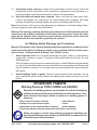
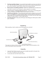
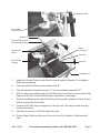
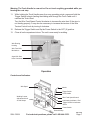
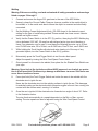
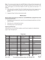
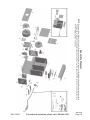
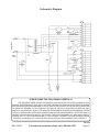
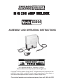
MIG 200 AMP WELDER
03664
ASSEMBLY AND OPERATING INSTRUCTIONS
®
3491 Mission Oaks Blvd., Camarillo, CA 93011
Visit our Web site at http://www.harborfreight.com
Copyright© 2003 by Harbor Freight Tools®. All rights reserved. No portion of this
manual or any artwork contained herein may be reproduced in any shape or
form without the express written consent of Harbor Freight Tools.
For technical questions and replacement parts, please call 1-800-444-3353
Specifications
ITEM
DESCRIPTION
Welding Current
30 ~ 200 amps AC
Welding Capacity
For welding 24 gauge metal and thicker
Duty Cycle
100% at 120 amps; 40% at 150 amps; 25% at 200 amps
Power Consumption
220 VAC, 12 amps at 60 Hz
Open Voltage
23V at 120A; 25V at 150A; 28V at 200A
Heat Control
30 ~ 200 amps, variable
Ground Cable
8 feet with heavy duty grounding clamp
Torch Power Cable
8 feet
Power Cord
3-core, double insulated, 12 AWG, U.L. approved
Thermal Overload with Light Automatic shutdown and restar t after cooldown
Wire Size
0.030" to 0.035"
Wire Spool Size
11-3/4" spool diameter
Overall Dimensions
27-3/4 (L) x 10-1/2 (W) x 25-3/4 (H) inches
Weight
79 lbs.
Accessories
Wheel kit, pulling handle, ground clamp, MIG torch,
Includes 1lb. of .032" wire
Save This Manual
You will need the manual for the safety warnings and precautions, assembly instructions,
operating and maintenance procedures, parts list and diagram. Keep your invoice with this
manual. Write the invoice number on the inside of the front cover. Keep the manual and
invoice in a safe and dry place for future reference.
Safety Warnings and Precautions
WARNING: When using tool, basic safety precautions should always be followed to reduce the risk of personal injury and damage to equipment.
Read all instructions before using this tool!
1.
Keep work area clean. Cluttered areas invite injuries.
2.
Observe work area conditions. Do not use machines or power tools in damp or wet
locations. Don’t expose to rain. Keep work area well lighted. Do not use electrically
powered tools in the presence of flammable gases or liquids.
3.
Keep children away. Children must never be allowed in the work area. Do not let them
handle machines, tools, or extension cords.
4.
Store idle equipment. When not in use, tools must be stored in a dry location to inhibit
rust. Always lock up tools and keep out of reach of children.
5.
Do not force tool. It will do the job better and more safely at the rate for which it was
intended. Do not use inappropriate attachments in an attempt to exceed the tool capacity.
6.
Do not overreach. Keep proper footing and balance at all times. Do not reach over or
across running machines.
7.
Dress properly. Do not wear loose clothing or jewelry as they can be caught in moving
parts. Protective, electrically non-conductive clothes and non-skid footwear are
recommended when working. Wear restrictive hair covering to contain long hair.
REV 06/05
SKU 03664
For technical questions, please call 1-800-444-3353.
Page 2
8.
Use the right tool for the job. Do not attempt to force a small tool or attachment to do
the work of a larger industrial tool. There are certain applications for which this tool was
designed. Do not modify this tool and do not use this tool for a purpose for which it was
not intended.
9.
Use eye and ear protection. Always wear ANSI approved, arc shaded, impact safety
full face shield (not included) when arc welding. Wear an ANSI approved dust mask or
respirator when working around metal, chemical dusts, fumes and mists.
10.
Maintain tools with care. Keep tools sharp and clean for better and safer performance.
Follow instructions for lubricating and changing accessories. Inspect tool cords
periodically and, if damaged, have them repaired by an authorized technician. The
handles must be kept clean, dry, and free from oil and grease at all times.
11.
Disconnect power. Unplug tool when not in use.
12.
Remove adjusting keys and wrenches. Check that keys and adjusting wrenches are
removed from the tool or machine work surface before plugging it in.
13.
Avoid unintentional starting. Be sure the switch is in the Off position when not in use
and before plugging in. Do not carry any tool with your finger on the trigger, whether it is
plugged in or not.
14.
Stay alert. Watch what you are doing, use common sense. Do not operate any tool when
you are tired.
15.
Check for damaged parts. Before using any tool, any part that appears damaged should
be carefully checked to determine that it will operate properly and perform its intended
function. Check for alignment and binding of moving parts; any broken parts or mounting
fixtures; and any other condition that may affect proper operation. Any part that is damaged
should be properly repaired or replaced by a qualified technician. Do not use the tool if
any switch does not turn On and Off properly.
16.
Guard against electric shock. Prevent body contact with grounded surfaces such as
pipes, radiators, ranges, and refrigerator enclosures.
17.
Replacement parts and accessories. When servicing, use only identical replacement
parts. Use of any other parts will void the warranty. Only use accessories intended for
use with this tool. Approved accessories are available from Harbor Freight Tools.
18.
Do not operate tool if under the influence of alcohol or drugs. Read warning labels
on prescriptions to determine if your judgment or reflexes are impaired while taking drugs.
If there is any doubt, do not operate the tool.
19.
Maintenance. For your safety, service and maintenance should be performed regularly
by a qualified technician.
20.
Use proper size and type extension cord. If an extension cord is required, it must be of
the proper size and type to supply the correct current to the tool without heating up.
Otherwise, the extension cord could melt and catch fire, or cause electrical damage to
the tool. This tool requires use of an 220 VAC extension cord of 20 amps minimum
capability (up to 30 feet), with wire size rated at 10 AWG. Longer extension cords require
larger size wire. If you are using the tool outdoors, use an extension cord rated for outdoor
use (signified by “WA” on the jacket).
SKU 03664
For technical questions, please call 1-800-444-3353.
Page 3
21.
Pacemaker safety warning. People with pacemakers should consult with their
physician(s) before using this product; operation of equipment in close proximity to a
heart pacemaker could cause interference or failure of the pacemaker.
22.
Use tools with both hands when required. Many tools such as chain saws, drills,
routers, and welders, etc., require the use of both hands when operating. This helps
maintain tool stability and keeps hands away from the working area of the tool.
Note: Performance of this tool may vary depending on variations in local line voltage. Extension cord usage may also affect tool performance.
Warning: The warnings, cautions, and instructions discussed in this instruction manual
cannot cover all possible conditions and situations that may occur. It must be understood by the operator that common sense and caution are factors which cannot be
built into this product, but must be supplied by the operator.
Arc Welding Safety Warnings and Precautions
Warning: This product, when used for welding and similar applications, produces chemicals known to the State of California to cause cancer and birth defects (or other reproductive harm). California Health & Safety Code 25249.5, et seq.
1.
Avoid electrical shock. Do not permit electrically live parts, cables, or electrodes to
contact skin, clothing, or gloves. Protective clothing should be free of holes, dry, and
ANSI approved.
This unit draws enough current to cause serious injury or death. Before turning the welder
on, check the electrode holder to be sure that there are no protruding screw heads, and
that all insulation is secure. Do not weld unless you are insulated from ground and the
work piece.
2.
Avoid breathing fumes or gases. They can cause serious health problems. Use an
active ventilation system directly above the welding area. Keep your head out of the
fumes.
Inhalation Hazard
Welding Produces TOXIC FUMES and GASSES.
Exposure to welding gasses can increase the risk of developing
certain cancers, such as cancer of the larynx and lung cancer. Also,
some diseases that may be linked to exposure to welding gasses or
fumes are:
• Early onset of Parkinson’s Disease
• Heart Disease
• Damage to the reproductive organs
• Ulcers
• Inflammation of the small intestine or stomach
• Kidney damage
• Respiratory diseases such as emphysema, bronchitis or pneumonia
Safety precautions, such as using natural or forced air ventilation and
wearing an ANSI approved respirator, are ESSENTIAL to reduce the risk
of developing the above illnesses.
REV 06/04
SKU 03664
For technical questions, please call 1-800-444-3353.
Page 4
3.
Avoid eye and body damage. Arc rays and infrared radiation can injure eyes and burn
skin. Wear ANSI approved arc shaded, impact safety full face shield and body protection.
Do not allow viewing by visitors without proper eye and body protection.
4.
Know proper arc welding practices. Read and understand the manufacturer’s
instructions, and well as your employer’s safety practices for arc welding.
5.
Connect only to a code approved power source. Connect only to a grounding power
source conforming to the National Electrical Code and Local Codes.
6.
Avoid fire and explosion. Remove flammable and explosive material from at least 35
feet from the welding arc to prevent welding sparks or molten metal from starting a fire.
Keep a type ABC fire extinguisher within easy reach. Thoroughly clean the object being
welded of any paint, grease, or other foreign material.
7.
Avoid being burned. Always wear ANSI approved welding gear: leather gloves, leather
apron, and shoes.
Unpacking
When unpacking, check to make sure the following parts are included.
MIG 200 Amp Welder
Wire Spool (1) not shown
220 VAC Power Cord
Torch Cable and Handle (2)
Ground Cable and Clamp (3)
If any parts are missing or broken, please call Harbor Freight Tools at the number on the
cover of this manual as soon as possible.
Assembly
1.
Insert the Torch Cable (connection end) into the cable strain relief on the end of the
unit. Refer to the photos on the next page.
2.
Loosen and unlock the Wire Tension Control.
SKU 03664
For technical questions, please call 1-800-444-3353.
Page 5
Cable Strain Relief
Wire Tension
Control and Lock
Bracket “A”
Current Collector (with
Wire Routing Housing)
Square
Connector “C”
Feed Control
Wheel
Gas Tube
Wire Routing
Housing
Outlet “B”
Receptacle “D”
3.
Attach the Current Collector (with Wire Routing Housing) to Bracket “A” and tighten.
Refer to photos above.
4.
Press the white Gas Tube onto the black outlet “B”.
5.
Plug the white tube Square Connector “C” into the matching receptacle “D”.
6.
Wind (or place) the welding wire onto the Wire Spool (not shown), and mount the Wire
Spool onto the Wire Feed Axis Mechanism. See photo on next page.
7.
Guide the welding wire into the Wire Routing Housing until it passes the Feed Control
Wheel, and into the Torch Cable.
8.
Connect a 220 VAC plug (not supplied) to the line cord. This step must be done by a
licensed electrician.
9.
Plug the line cord into a 220 VAC electrical outlet.
10.
Flip the Power Switch on the front of the unit to the ON (I) position. The blower will
start.
SKU 03664
For technical questions, please call 1-800-444-3353.
Page 6
Warning: The Torch Handle is now active. Do not touch anything grounded while performing the next step.
11.
While holding the Torch Handle away from any grounding points, press and hold the
Trigger Switch to begin feeding the welding wire through the Torch Cable until it
reaches the Torch Head.
Turn the Wire Feed Speed Control clockwise to increase the wire feed. If the wire is
not feeding properly, It may also be necessary to increase the tension of the Wire
Tension Control knob by turning it clockwise.
12.
Release the Trigger Switch and flip the Power Switch to the OFF (0) position.
13.
Close all unit compartment doors. The unit is now ready for welding.
Wire Routing
Housing
Wire Feed Axis
Mechanism
Argon/CO2 Gas
Hose Connector
Operation
Controls and Indicators
Wire Spool
Nozzle
Trigger Switch
Torch Handle
Welding Current
Adjustment Knob:
30~200 Amps
Wire Feed Speed Control
Overheating Indicator - Red
Trigger Switch On Indicator Green
Power Switch
Ground Clamp
REV 03/05
SKU 03664
For technical questions, please call 1-800-444-3353.
Page 7
Welding
Warning: Before arc welding, read and understand all safety precautions and warnings
listed on pages 2 through 5.
1.
Connect and secure the Argon/CO2 gas hose to the rear of the MIG Welder.
2.
Securely clamp the Ground Cable Clamp as close as possible to the metal object to
be welded, or to the metal work bench where the object is mounted and electrically
connected.
3.
Set the Welding Current Adjustment Knob ( 30~200 Amps) to the desired current
setting for the type of metal being welded.Thinner metals use lower current. Heavier
metals use higher current.
4.
Verify that the Power Switch is in the OFF (0) position, then plug the MIG Welder plug
into a dedicated, 220 VAC, 20 amp line with delayed action type circuit breaker or
fuses. If an extension cord is used, it must have the following wire size: up to 30 feet,
use 10 AWG size wire; 30 to 50 feet, use 8 AWG wire; Over 50 feet, use 6 AWG wire.
5.
While holding the Torch Handle with electrode wire clearly out of the way of any
grounded objects, turn the Power Switch to the ON (I) position.
6.
Momentarily press the Torch Trigger Switch to test the wire feed speed.
Adjust the speed by turning the Wire Feed Speed Control knob.
7.
Orient yourself on the area to be welded, then place the Arc Shaded Face Shield over
your eyes.
Warning: Never look at the ignited arc without ANSI approved, arc shaded, eye protection in a full face shield. Permanent eye damage or blindness can occur. Skin burns can
occur. Never breath arc fumes.
8.
Press (and hold) the Torch Trigger Switch and stroke the area to be welded with the
electrode wire to ignite the arc.
Never tap the electrode wire into the welding surface to ignite the arc. This damages
its external coating on the electrode which prevents oxygen in the air from coming into
contact with the molten metal, causing it to oxidize.
9.
Once the arc is ignited, tilt the electrode wire forward at an angle of about 35°. Refer
to the illustration below.
The wire feeds automatically at a speed dependent on the Min. or Max. current
setting. The wire speed can also be adjusted using the Wire Feed Speed Control.
SKU 03664
For technical questions, please call 1-800-444-3353.
Page 8
Note: If too much current is drawn from the MIG Welder, the Thermal Overload protector will
activate, the red Overheating indicator will light, and the Arc Welder will turn off until it cools
down. If this happens, turn the Power Switch to the OFF (0) position and wait about 3 ~ 5
minutes.
10.
When the weld is complete, lift the Torch Handle electrode wire clearly away from any
grounded object, lift your Face Shield, and turn the Power Switch to the OFF (0)
position.
11.
Unplug the Power Cord from the electrical outlet.
Maintenance
Warning: Before performing any maintenance on the MIG Welder, unplug the Power Cord
from the electrical outlet.
1.
Periodically using compressed air, open the top and side panels and blow out all dust
from the interior.
2.
Store the unit in a clean and dry location.
3.
Periodically clean out the Torch Head.
Replacing the Wire Reel
When the wire on the Feed Reel is used up, you will need to replace it as described on
page 6, step 6 through step 13.
Parts List
Part
Description
Part
Description
1
Case
17
Wire Spool
2
Folding Cover
18
Brake
3
Vent Cover
19
Fan
4
Coil Cover
20
5
Transformer Cover
6
Part
Description
32
Panel
33
Wire Tension Control/
Lock
Front Panel
34
Feed Control Wheel
21
LED Display
35
Current Collector
Current Adjusting Knob
22
Power Switch
36
Wheels
7
Main Transformer
23
Wire Speed Control
37
Right handle
8
Circuit Board
24
Wire Speed Knob
38
Left handle
9
Diode Board
25
Handle Bracket
39
Trigger
10
Star ter
26
Handle
40
Nozzle Tube
11
Throttle
27
Input Line Cord
41
Tip
12
Ground Clamp
28
Cable Strain Relief
42
Nozzle
13
Ground Cable
Tip
Ground Terminal
Torch & Hose Assy
(Contains par ts 37-44)
43
14
29
44
Cord
15
Retainer
30
Electric Motor
16
Back Panel
31
Panel
45
1 Lb. Spool of .032"
Welding Wire
REV 06/05
SKU 03664
For technical questions, please call 1-800-444-3353.
Page 9
Page 10
For technical questions, please call 1-800-444-3353.
SKU 03664
Assembly Diagram
NOTE: Some parts are listed and shown for illustration purposes only and are not available individually as replacement parts.
This diagram and the parts list that preceded it show the major components of this unit and are not comprehensive.
Part 45 - Welding Wire - not shown.
REV 06/05
Schematic Diagram
PLEASE READ THE FOLLOWING CAREFULLY
THE MANUFACTURER AND/OR DISTRIBUTOR HAS PROVIDED THE PARTS DIAGRAM IN THIS
MANUAL AS A REFERENCE TOOL ONLY. NEITHER THE MANUFACTURER NOR DISTRIBUTOR MAKES
ANY REPRESENTATION OR WARRANTY OF ANY KIND TO THE BUYER THAT HE OR SHE IS QUALIFIED
TO MAKE ANY REPAIRS TO THE PRODUCT OR THAT HE OR SHE IS QUALIFIED TO REPLACE ANY
PARTS OF THE PRODUCT. IN FACT, THE MANUFACTURER AND/OR DISTRIBUTOR EXPRESSLY STATES
THAT ALL REPAIRS AND PARTS REPLACEMENTS SHOULD BE UNDERTAKEN BY CERTIFIED AND LICENSED TECHNICIANS AND NOT BY THE BUYER. THE BUYER ASSUMES ALL RISK AND LIABILITY
ARISING OUT OF HIS OR HER REPAIRS TO THE ORIGINAL PRODUCT OR REPLACEMENT PARTS
THERETO, OR ARISING OUT OF HIS OR HER INSTALLATION OF REPLACEMENT PARTS THERETO.
REV 06/05
SKU 03664
For technical questions, please call 1-800-444-3353.
Page 11