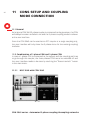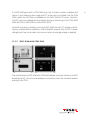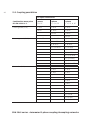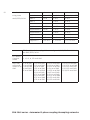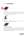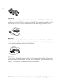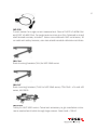
1
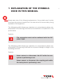
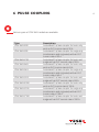
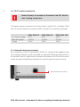
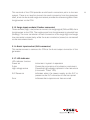
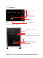
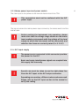
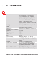
1
CDN 3063 series
Automated 3-Phase
Coupling/decoupling
networks
User Manual
601-315D
CDN 3063 series
Automated 3-Phase
coupling/Decoupling
networks
User Manual
CDN 3063 series - Automated 3-phase coupling/decoupling networks
contentS
1
Explanation of the symbols used in this manual
2Introduction
2.1 General description
2.1.1 CDN 3063 automated 3-phase coupling/decoupling networks
3
Safety instructions
3.1 General
4Installation
4.1 Installation of a EUT power emergency off switch
5
Applicable safety standards
6
Pulse coupling
6.1. Combination wave and ring wave test
6.1.1 Combination wave (CW) - Surge generator
6.1.2 Ring wave (RW)
6.2 Electrical fast transient EFT (burst)
7
First step
8
Installation of the CDN 3063
9
Main frame description
9.1 Front panel CDN 3063
9.1.1 32 A versions
9.1.2 63 and 100 A versions
9.1.3 EUT output connection
9.1.4 Ground reference terminal
9.1.5 Surge input sockets (Fischer connector)
9.1.6 Burst input socket (SHV connector)
9.1.7 LED indicator
9.2 Rear panel
9.2.1 32 A versions
9.2.2 63 A versions
9.2.3 Mains power input and power switch
9.2.4 EUT input supply
9.2.5 3-phase AC EUT mains input
9.2.6 Colour codes of a 3-phase system
5
7
7
8
9
9
12
13
14
15
16
16
17
17
19
20
21
21
21
21
22
22
23
23
23
24
24
24
25
25
26
26
9.3 Phase rotation indication
28
9.3.1 2- or 1-phase AC EUT mains input
30
9.3.2 Phase rotation indication using single- or two lines EUT power mains 30
9.3.3 DC EUT input
31
9.3.4 Signal routing card “system in interface”
32
9.3.5 Signal routing card “system out interface”
32
9.3.6 Fan and cooling concept
33
10 Test setup setting
34
10.1 Applicable safety standards
34
10.2 Test execution
35
10.3 Dangers concerning the generator
36
10.4 Dangers concerning the EUT
36
10.5 Test setup
37
10.6 Mounting in a 19” rack
39
11 CDNs setup and coupling mode connection
40
11.1 General
40
11.2 Combination of single phase CDN and three phase CDN
40
11.2.1NSG 3040 with CDN 3063
40
11.2.2NSG 3060 with CDN 3063
41
11.2.3NSG 3060 with CDN 3063 and CDN 3061
(for PQT test 1-phase testing)
42
12 Coupling mode selection at the generator user interface
43
12.1 Surge output/burst output
43
12.2 Manual CDN
43
12.3 ANSI and IEC coupling mode
44
12.3.1 IEC coupling
44
12.3.2 ANSI coupling
45
13 Technical data coupling network CDN 3063
47
13.1Dimensions/weight
47
13.2 Coupling possiblities
48
14 Maintenance and function check
51
14.1 General
51
14.2Cleaning
51
14.3 Function check
52
14.4 Calibration
52
15Warranty
53
16 CE conformity
54
17Accessories
55
18 System limits
58
19 Addresses
60
1 explanation of the symbols
used in this manual
Please take note of the following explanations of the symbols used in order
to achieve the optimum benefit from this manual and to ensure safety during
operation of the equipment.
The following symbol draws your attention to a circumstance where nonobservation of the warning could lead to inconvenience or impairment in the
performance.
Example:
This connection must not be confused with the EUT
power input.
The following symbol draws your attention to a circumstance where nonobservation of the warning could lead to component damage or danger to the
operating personnel.
Example:
Never connect or disconnect the EUT while the test
system is performing a test.
Never connect or disconnect the coupling path while
the test system is performing a test.
5
6
Lethal danger from high voltages and the risk of radiating illegal electromagnetic interference.
The NSG 3040/3060 with its CDN may only be installed
and used by authorised and trained EMC specialists
(electrical engineers).
The NSG 3040/3060 with its CDN must only be used
for EMC tests as set down in these operating instructions.
Personnel fitted with a heart pacemaker must not
operate the instrument and must not be in the vicinity
of the test rig while it is in operation.
Lethal danger from high voltages and the risk of high
levels of electromagnetic radiation being generated.
The system must only be used for EMC test purposes
as set down in these operating instructions.
When the system is used in conjunction with options,
accessories or other equipment the safety instructions
concerning those devices must also be observed.
CDN 3063 series - Automated 3-phase coupling/decoupling networks
2introduction
2.1 General description
The NSG 3040/3060 test systems are designed primarily for cable-borne
transient interference tests as specified in the European generic standard
IEC/EN 61000-6-1 covering equipment for household, office and light industrial use, and IEC/EN 61000-6-2 for applications in industrial environments, in
accordance with the requirements of the basic standards. IEC/EN 61000-4-4,
-5, -12 as well as -8 and -9 .
The EU directive no. 2004/108/EEC (for the assignment of the CE symbol) refers
back to this standard for this type of equipment.
The CDN 3063 is modular and automated coupling/decoupling network,
depending on the version it can inject surge and/or burst pulses.
The modularity has the advantage that upgrades can be performed at any time
in a cost effective way, ensuring a safe investment in future laboratory needs.
The CDN 3063 in connection with the NSG 3060 can handle the special ANSI
C62.41 recommendation. This standard requires that the EUT power voltage
level has to be taken into account.
In combination with NSG 3040 the CDN 3063 is not able to take EUT frequency
and EUT voltage into account like the NSG 3060.
7
8
2.1.1 CDN 3063 automated 3-phase coupling/decoupling networks
CDN 3063 series is a family of 3-phase coupling networks, rated to test equipment of 16 A, 32 A, 63 A or 100 A per phase. They are able to couple combination wave - ring wave pulses up to 6.6 kv and EFT pulses up to 4.8 kV.
No PQT test can be selected since the three phase PQT test recommends other
test units like the Teseq Profline 2100 system. 1-phase PQT test is only available
in the CDN 3061 and NSG 3040.
CDN 3063 series - Automated 3-phase coupling/decoupling networks
3 safety instructions
The coupling networks CDN 3063 are intended for use with surge and/or burst
generators. These generators produce high voltage test pulses with high energy.
Improper or careless handling can be fatal! The instrument must only be accessible to trained persons.
These operating instructions, together with the generator manual, form an
essential part of the equipment and must be available to the operator at all
times. All the safety instructions and advice notes are to be observed.
Neither Teseq AG, Luterbach, Switzerland, nor any of the subsidiary sales
organisations can accept any liability for personal, material or consequential
injury, loss or damage that may result from improper use of the equipment
and accessories.
3.1 General
Use of the coupling device in combination with the generator is restricted to
authorized and trained specialists.
The user is directly responsible for ensuring that the test rig does not cause
excessive radiated interference which could affect other instrumentation. The
test system itself does not produce any excessive EM radiation. However, the
injection of interference pulses into a EUT can result in it and/or its associated
cables radiating electromagnetic energy.
To avoid problems with unwanted radiation the standards organisations recommend that the test rig is operated inside a Faraday cage.
9
10
Because of its type of construction the instrument is
not suitable for use in an explosive atmosphere.
Persons fitted with a heart pacemaker must not operate
the instrument nor approach the test rig while a test is
being executed.
Only approved accessory items, connectors, adapters, etc. are to be used to
ensure save operation.
Upon switching on the generator, it will perform a self
test. This includes the function of the EUT coupling
relays and the detection of the EUT input power for
synchronisation. Therefore the EUT output is to be considered as carrying EUT power all the times!
The test rig must provide adequate insulation protection for up to 8 kV surge
and burst. Particular care should be given to the connections between the CDN
and the equipment under test (EUT).
The EUT may only be tested when placed inside a suitable protective enclosure which should provide protection against flying fragments, fire and electric
shock.
The pulse voltage must not be able to find its way to unearthed metal objects
in the event of the EUT failing.
Only use the instrument in a dry room.
Never leave the instrument unattended when the EUT is switched on.
Do not open the instrument. Repairs and adjustments must only be carried out
by qualified maintenance personnel.
CDN 3063 series - Automated 3-phase coupling/decoupling networks
Do not continue to use the CDN in case of mechanical damage. The CDN
housing and the cables have both insulating and a screening function, which
can only be assured while the housing is intact. Return the damaged CDN to a
Teseq service center immediately for repair.
11
12
4installation
The test system conforms to protection class 1. Local installation regulations
must be respected to ensure the safe flow of leakage currents.
Operation without a protective earth connection is forbidden!
Switch off EUT power before accessing EUT power IN
or OUT terminals.
The terminals of the three phases CDN 3063 are accessible with the included insulated Allen key.
Two independent protective earth connections are necessary (for the test
system and the EUT). These must be connected back to the local permanent
installation or to a fixed, permanent protective earth conductor.
Operate the equipment only in dry surroundings. Any condensation that occurs
must be allowed to evaporate before putting the equipment into operation. Do
not exceed the permissible ambient temperature or humidity levels. Use only
officially approved connectors and accessory items.
Ensure that a reliable return path for the interference current is provided
between the EUT and the generator. The reference ground plane and the earth
connections to the instruments, as described in the relevant test standard,
serve this purpose well.
Since the instrument works, on principle, with two independent power supplies
CDN 3063 series - Automated 3-phase coupling/decoupling networks
(one for the coupling network and one for the EUT), the CDN 3063 must be
disconnected from both sources before any modifications to the test rig are
undertaken. Besides the mains connections themselves, certain components
also operate at high voltages, which are not provided with any form of extra
protection against being accidentally touched.
4.1. Installation of a power emergency off switch
The CDN itself has an internal power switch to control EUT power ON/OFF,
accessible via the user interface or the software, but nerveless, it is recommended to connect the EUT power through a properly rated circuit breaker
and an emergency off button as per IEC/EN 61010-1:2001. In order to ensure
an easy and quick access, the button should be located close to the test setup
and should be clearly and visibly labelled as a device for “Emergency power
ON/OFF” switching.
The test setup should only be accessible to trained
persons.
Dimensioning of mains supply and rating of fuse protection of AC or DC power
supply must conform with National prescriptions and EUT requirements.
Inappropriate arrangement, mounting, cabling or handling of the device under
test or the protective elements can make the protective features that are incorporated in the design of the instrument worthless.
13
14
5 Applicable safety standards
The construction of the instrument conforms to the safety requirements and
offers everything necessary for safe and efficient operation.
Development and manufacture is in compliance with ISO 9001. The system
complies with the safety requirements of IEC/EN 61010-1 (safety requirements
for electrical equipment for measurement, control and laboratory use).
All mains power driven types of units are designed for high voltage working
safety.
The interference immunity has been tested in accordance with EN 60326-1. It is
the user’s responsibility to ensure that the test rig does not emit excessive electromagnetic interference (EMI) which might affect other items of equipment.
The test system itself does not produce any excessive radiation; however, the
injection of interference pulses into the EUT can result in the device and/or
its associated cables starting to radiate EMI. To avoid radiating of unwanted
interference the test rig might be operated in a Faraday cage.
Since the purpose of the test system is to produce interference signals for
interference immunity testing, the requirements in IEC/EN 61000-6-x series
concerning limiting the radiated EMI can only be complied with by operating
the test system inside a Faraday cage.
CDN 3063 series - Automated 3-phase coupling/decoupling networks
6 Pulse coupling
Various types of CDN 3063 models are available.
TypeDescription
CDN 3063-B32 Automated 3-phase coupler for burst only
with an EUT current rate of 32 A
CDN 3063-S32 Automated 3-phase coupler for surge only
(combination and ring wave) with an EUT
current rate of 32 A
CDN 3063-C32 Automated 3-phase coupler for burst and
surge with an EUT current rate of 32 A
CDN 3063-B63 Automated 3-phase coupler for burst only
with an EUT current rate of 63 A
CDN 3063-S63 Automated 3-phase coupler for surge only
(combination and ring wave) with an EUT
current rate of 63 A
CDN 3063-C63 Automated 3-phase coupler for burst and
surge with an EUT current rate of 63 A
CDN 3063-B100 Automated 3-phase coupler for burst only
with an EUT current rate of 100 A
CDN 3063-S100
Automated 3-phase coupler for surge only
(combination and ring wave) with an EUT
current rate of 100 A
CDN 3063-C100
Automated 3-phase coupler for burst and
surge with an EUT current rate of 100 A
15
16
6.1. Combination wave and ring wave test
The surge test (in compliance with IEC/EN 61000-4-5, ANSI 62.41+45 and IEC/
EN 61000-4-12) simulates high voltage/high energy interference as experienced
with a lightning strike. Generally speaking the interference finds its way into
equipment by way of the mains supply.
This kind of interference can affect equipment in either of two ways. Firstly, the
interference can be coupled directly into the equipment via the mains supply.
The interference is conveyed directly from the source (e.g. lightning strike to
external power cables). Every item of equipment connected to this power
source will be affected by the interference pulses.
Surge pulse interference can also occur on signal and data lines through coupling
effects and electrical discharges. For this, the CDN 117/118 is recommended.
The test system enables tests to be carried out using both coupling methods.
The EUT is connected to the mains power socket on the front panel of the test
system for the direct mains injection test. Externally coupled tests require the
interference to be superimposed on the EUT power feed cable via an external
coupling unit that is connected to the Surge output on the front panel of the
system.
6.1.1 Combination wave (CW) - Surge generator
The combination wave test involves the generation of high voltage surge pulses
as specified in the international standard IEC/EN 61000-4-5 and ANSI C62.41+45.
The test pulses are injected directly into the EUT power supply lines. The EUT
obtains its power from the EUT power outlet on the CDN of the test system
where the voltage has the interference signal superimposed on it.
Surge voltage of up to 6.6 kV which follows the 1.2/50 µs curve (opencircuit)
Surge current of up to 3.3 kA which follows the 8/20 µs curve (short circuit)
CDN 3063 series - Automated 3-phase coupling/decoupling networks
6.1.2 Ring wave (RW)
The ring wave is specified in the ANSI IEEE Std C62.41 and IEC/EN 61000-4-5.
The open-circuit voltage waveform is defined by the following parameters:
Rise time: 0.5 µs
Ringing frequency: 100 kHz
No short-circuit current waveform is specified for the 100 kHz ring wave.
Because the purpose of the ring wave is not to provide high-energy stress
to the EUT, the precise specification of the current waveform is unnecessary.
The test pulse is injected directly into the EUT power supply lines as they pass
through the CDN of the test system. The EUT obtains its power from the EUT
power outlet on the CDN of the test system where the voltage has the interference signal superimposed on it.
6.2 Electrical fast transient EFT (burst)
Burst tests (in compliance with IEC/EN 61000-4-4) simulate the high voltage/high
frequency interference pulses typically produced when an inductively loaded
switch is operated. Such interference always occurs when a current through
an electromagnetic device, e.g. motor, circuit breaker, relay, fluorescent lamp,
etc. is switched on or off.
This kind of interference can affect other equipment in either of two ways.
First, the interference can be coupled directly into the target equipment via
the mains power cable. Secondly the interference can be transmitted from
the source along the mains power cable connected to the target. Interference
from the mains can reach any other piece of equipment connected to the same
power source in a similar way.
Alternatively, the interference can be coupled capacitive into any target device
in the vicinity. Teseq offers such capacitive coupling clamp device like CDN 3425.
17
18
The test system enables a test to be carried out using both coupling methods.
The EUT is connected to the mains power socket on the front panel of the test
system for the direct mains injection test. Capacitive coupled tests require the
interference to be superimposed on the EUT power feed cable via an external
coupling unit that is connected to the Burst output on the front panel of the
system.
The coupling network CDN 3063 serves to inject standardized pulses into the
mains supply to the device under test called for in the international standard
IEC/EN 61000-4-4:
Fast transient (Burst) up to 4.8 kV which follows the 5/50 ns curve (50 Ω condition).
CDN 3063 series - Automated 3-phase coupling/decoupling networks
7First step
This chapter contains a short check-list with steps that should be taken before
the instrument is connected to the generator, switched on and put into operation.
Check the packaging for signs of damage in transit. Any damage should be
reported immediately to the transportation company. Due the weight of the
CDN 3063, a two man lift is needed to prevent injury. Lift the CDN 3063 coupling
network out of its packaging by taking hold of the front mounted grips.
Check, using the following list, that all the items ordered as well as their accessories have been delivered:
1. CDN 3063 coupling network unit
2. Operating instruction (*.pdf or WIN 3000 CD)
3. 1 Mains power cable for the CDN
4. 1 grounding ship (to ref. ground)
5. 2 HV cable with Fischer/Fischer connector (in C or S versions)
6. 1 HV cable with SHV/SHV connector (in B or C versions)
7. 1 System cable
8. 1 Allen key for output connector
9. Ordered options
Check the instrument for signs of transport damage. Any damage should be
reported to the transportation company immediately.
19
20
8Installation of the CDN 3063
The mains power voltage indicated on the instrument must accord with the
local supply voltage (mains voltage: 85–265 VAC, universal power unit, mains
frequency: 50–60 Hz).
Mains switch
Fuse-holder with fuses
2 x 3.15 AT
Mains power supply
To insert a fuse, pull the fuse-holder out of the connector, insert 2 fuse cartridges 2 x 3.15 AT (slow blow) into the holder and put the holder back.
Plug the mains cable into a power outlet with a solid earth connection. Place
the test system such that there is sufficient free space around the cooling air
inlets on both sides and behind the fan outlet on the rear panel switch on and
operate as stated in the accompanying instructions.
CDN 3063 series - Automated 3-phase coupling/decoupling networks
9 main frame description
21
9.1 Front panel CDN 3063
9.1.1 32 A versions
Surge input sockets
Burst input socket
LED indication
EUT output connection
Ground reference terminal
9.1.2 63 A and 100 A versions
Burst input socket Surge input sockets
LED indication
EUT output connection
Ground reference terminal
22
9.1.3 EUT output connection
Never attempt to connect or disconnect an EUT while a
test is being carried out.
The power output connection for three phase 5 cord EUTs. A suitable “Allen
key” to screw /unscrew the power leads is included in the delivery package.
EUT current range Max.wire gauge Torque CDN 3063-32
32 A
10 mm²
5 Nm
CDN 3063-63
63 A
16 mm²
5 Nm
CDN 3063-100
100 A
25 mm²
5 Nm
9.1.4 Ground reference terminal
As mentioned in the EFT standard IEC 61000-4-4, the generator together with
the coupling network has to be placed on a ground reference plane which is
connected to earth. A good earth connection between the CDN and the earth
reference plate is absolutely essential for performing burst tests correctly.
Ground reference terminal
CDN 3063 series - Automated 3-phase coupling/decoupling networks
This terminal of the CDN provides a solid earth connection point to the test
system. There is no need to connect the earth connector from the generator
itself, since the burst and surge connectors provide the reference ground from
the generator to the CDN.
9.1.5 Surge input sockets (Fischer connector)
These sockets (High, Low) serve to connect the surge signal (CW and RW) from
the generator to the CDN. The surge output from the generator is potential free
(floating). The inner conductor of each connector is the surge high and surge
low connection respectively while the outer conductor (screen) is connected
to the instruments earth.
9.1.6 Burst input socket (SHV connector)
This socket serves to connect the CDN to the burst output connector of the
generator.
9.1.7 LED indicator
LED indicator function
Power on
Pulse High voltage active
EUT-Power on Error Instrument / system in operation
Shows the occurrence of a pulses or a test event
Shows that high voltage is present in the instrument
(in line with “Pulse” LED)
Indicates when the power supply to the EUT is
present at the EUT connector on the front panel
Indicates that a system error has occurred
23
24
9.2 Rear panel
9.2.1 32 A versions
Phase rotation indication
Mains input and power
switch
Signal routing card
“system in interface”
Signal routing card
“system out interface”
EUT input supply
9.2.2 63 A and 100 A versions
Mains input and power switch
Signal routing card “system out interface”
Signal routing card “system in interface”
Phase rotation control button
Phase rotation indication
EUT input supply
CDN 3063 series - Automated 3-phase coupling/decoupling networks
9.2.3 Mains power input and power switch
The main input is the power to the internal electronics of the CDN.
This connection must not be confused with the EUT
power input.
The input contains the mains power input connector, the mains switch and the
mains fuses.
Before putting the instrument into operation, please
make sure that the voltage range shown on the mains
input module corresponds with the voltage of the local
supply to which the instrument will be connected, and
whether the fuses are correctly rated (2 x 3.15 AT).
9.2.4 EUT input supply
Burst and surge interference signals are coupled into
this supply line internally.
The power source connected to this connector provides
the power for the EUT.
Special care must be taken to use the right phase line
from the EUT input at the EUT output connector.
Depending on countries, different colour codes are used.
Please refer to the EUT input section in this manual to
verify the coding.
25
26
Because of the capacitors in the internal coupler, earth
leakage currents of up to 4 A can occur in the EUT power
supply network.
The test system must therefore be correctly earthed
and be powered from a supply that is not protected by
a residual current detector (RCD).
If the CDN test system is connected to a DC power source for the EUT, care
must be taken to ensure that the polarity at this connector corresponds with
that at EUT power connector.
9.2.5 3-phase AC EUT mains input
The EUT main input is equipped with screw terminals type Phoenix HDFK 10-HV,
resp. HDFK 25 with following parameters:
CDN type/
max.
Wire gauge
max.
Phoenix type current
voltage
CDN 3063-32
57 A
Solid
min. 0.5 mm² 1000 V
HDFK 10-HV
max. 16 mm²
Stranded min. 05 mm²
max. 10 mm²
AWG/kcmil min. 20
max. 6
CDN 3063-63/100 125 A
Solid
min. 6 mm² 600 V
HDFK 25
max. 35 mm²
Stranded min.10 mm²
max. 25 mm²
AWG/kcmil min. 10
max. 2
Torque
min. 1.5 Nm
max. 1.8 Nm
min. 4 Nm
max. 4.5 Nm
9.2.6 Colour codes of a 3-phase system
Conductors of a three phase system are usually identified by a color code, to
allow for balanced loading and to assure the correct phase rotation. Colors
used may adhere to International Standard IEC 60446, older standards, or to
no standard at all, and may vary even within a single installation. For example,
in the U.S. and Canada, different color codes are used for grounded (earthed)
and ungrounded systems.
CDN 3063 series - Automated 3-phase coupling/decoupling networks
Countries /
L1
L2
L3
Neutral Ground /
5 wire power cord
protective earth
United States
(common practice)
Black
Red
United States
With or
gray
Green, green/yellow triped or a bare
copper wire
Brown
Orange Yellow
(Delta)
or Violet
(Wye)
Gray or
white
Green
Canada (mandatory)
Red
Black
Yellow
White
Green (or bare
copper)
Canada (isolated 3-phase
Orange
Brown
Yellow
White
Green
Brown
Black
Grey
Blue
Green/yellow
striped
Older European (IEC 60446, Black or Black or
varies by country)
brown
brown
Black or
brown
Blue
Green/yellow
striped
UK until April 2006, Hong
Kong until April 2009,
South Africa, Malaysia
Red
Yellow
Blue
Black
Green/Yellow
striped (green on installa-
Pakistan
Red
Yellow
Blue
Black
Green
India
Red
Yello
Blue
Black
Green
Austalie and New Zealand
(per AS/NZS 3000:2000
section 3.8.1)
Red
(prev. yel-
Blue
Black
Green/yellow stiped (green on very
old installations)
Yellow
Green
Red
Light
blue
Green/yellow
striped
(alternative practice)
Blue
installations)
Europe and many other
countries, including UK
from April 2004 (IEC 60446),
Hong Kong from Juli 2007
People’s Republic of China
(per GB 50303-2002
Section 15.2.2)
tions approx. before 1970)
With
low)
Peak impulse voltages of up to 630 V can occur on these power lines. Such
voltages can, under certain circumstances, destroy AC/DC power supplies. It
is the user’s responsibility to ensure adequate protection being provided at the
inputs of the source.
27
28
9.3 Phase rotation indication
This important and easy to read feature guaranties a correct coupling especially
in synchronous mode.
The phase rotation identification at the back off the CDN units shows clearly,
if all phases are connected and if the rotation of L1, L2 and L3 are correctly
set, this is important especially in synchronous mode. The phase angle shift of
120° is a function of the actual rotational angle, following a definite order. For
clockwise rotation the phase sequence order is 1-2-3.
However, if we reverse the rotation winding 2’s waveform will be leading 120°
ahead of 1 instead of lagging, so the coupling point of a synchronous coupling
will be wrong, since the zero crossing of L1 is measured and calculated for the
other lines. The counter clockwise rotation phase sequence is 2-1-3, which is
wrong.
To test the proper phase rotation of the EUT Power Input, push the button
beside the LED’s - phase rotation will be shown by the LED’s as long as the
button is pushed.
CDN 3063 series - Automated 3-phase coupling/decoupling networks
This is a correct EUT power setting, all phases are connected (all lines indication
are on) and the rotation is right too.
The EUT power lines provide all power, but the phase rotation is wrong. In this
case the exchange of line L1, L2, or L3 will solve the rotation problem.
Not all EUT power lines provide power and the phase rotation is wrong too. All
phase of the EUT in power need to be checked and re-plugged.
29
30
9.3.1 2- or 1-phase AC EUT mains input
The CDN is able to handle also two and single phase power mains. In this case
the colour code is different.
It is the user’s responsibility to ensure that in two or
1-phase system, the phases are correctly set at the
input as well as at the EUT output connector, in this case
the phase roatation detector does not work properly.
Following lines have to be used to guaranty the correct coupling mode selection:
2-phase system: L1, L2, N, PE
1-phase system: L1, N, PE
9.3.2 Phase rotation indication using single- or two lines EUT power
mains
The phase rotation indication is made for 3-phase EUT
power mains. In single or two phase application the
indication will show different behavior.
As soon as the three phase input is used for single or two phase EUT application,
the rotation indication will not work, resp. will not indicate properly and always
showing error. However, the EUT power mains will anyway go through the CDN
with any damage or harm.
CDN 3063 series - Automated 3-phase coupling/decoupling networks
Indication in single-phase mode
If L1 is connected then L2 will be dark while L3 will light up softly as well and
the red rotation led will be on.
Indication in two-phase mode
If L1 and L2 are connected then L3 will light up softly as well and the red and
green rotation led will be on dimly.
9.3.3 DC EUT input
Pin allocation for DC voltages: L1 = Positive (+), N = Negative (-)
In the case of DC applications, the positive and negative lines have to be connected to L1 and N respectively.
The polarity at this EUT power input connector must be the same as at the EUT
output connector.
31
32
9.3.4 Signal routing card “system in interface”
This is for the system interface between generator and the coupling network.
This “System in” connector need a link to the “Master controller” of the generator. The system cable is part of the delivery.
9.3.5 Signal routing card “system out interface”
This connection is used if additional automated accessories need to be connected. Otherwise the termination plug has to be connected and the screws
need to be tightened. The termination plug is part of the generator.
CDN 3063 series - Automated 3-phase coupling/decoupling networks
9.3.6 Fan and cooling concept
All Teseq CDN 3043 series instruments have been designed with a dynamic
cooling concept. Internal elements suspected to warm up in any condition,
especially the Surge pulse decoupling chokes, are equipped with thermal
sensors. So at standby or for lower EUT currents, when there are nearly no
dissipation losses in the CDN, and so no heat generation, there is no need of
cooling and the fans will turn at a very low speed, generating no noise.
As soon as the EUT current raises, heat will be generated in the housing, the
internal control electronics will detect this and increase fan speed to improve
cooling.
In case of international or uninternational overloading, there will be a point
where even full speed cooling will no more be sufficient, at this moment the
CDN 3043 will switch OFF EUT power through the built in EUT power contractor,
and so avoid destruction of the instrument (risk of fire). The CDN 3040 control
electrics will also send a message back to the NSG 3040 which will immediatly
stop the firing of pulses.
That way CDN 3043 series give large overload capabilities, allowing up to 1,5
nominal current loading for 10 to 20 minutes, as well as high inrush currents
or peak laods.
33
34
10Test setup setting
10.1 Applicable safety standards
Development and manufacture is in compliance with ISO 9001.
The instrument complies with the safety requirements of IEC/EN 61010-1 (Safety
requirements for electrical equipment for measurement, control and laboratory
use).
The interference immunity has been tested in accordance with EN 61326-1.
It is the user’s responsibility to ensure that the test rig does not emit excessive
electromagnetic interference (EMI) that might affect other items of equipment.
The test system itself does not produce any excessive radiation; however, the
injection of interference pulses into the EUT can result in the device and/or its
associated cables starting to radiate EMI. To avoid radiating unwanted interference the standards organisations recommend that the test rig be operated in
a Faraday cage.
Since the purpose of the test system is to produce interference signals for
interference immunity testing, the requirements in IEC/EN 61000-6-1,-2,-3,-4
concerning limiting the radiated EMI can only be complied with by operating
the test system inside a Faraday cage
CDN 3063 series - Automated 3-phase coupling/decoupling networks
10.2 Test execution
During a test, the EUT together with its accessories and
cables are to be considered as being live at all times.
The test system must be stopped and the EUT supply
disconnected before any work is carried out on the EUT.
The EUT is to be tested only in a protective cage or
under a hood which provides protection against electric
shock and all manner of other dangers pertaining to the
particular EUT (see: Dangers concerning the EUT).
The safety instruction concerning all the instruments
and associated equipment involved in the test rig have
to be observed.
The configuration of the test rig is to be strictly in
compliance with the methods described in the relevant standard to ensure that the test is executed in a
standard-conforming manner.
35
36
10.3 Dangers concerning the generator
Local burning, arcing, ignition of explosive gases.
Danger from the resultant EUT supply current
caused by a flashover or breakdown resulting from
the superimposed high voltage effects.
Dangers from a disrupted EUT.
Disturbance of other, unrelated electronics, telecom
munications, navigational aids and heart pacemak ers through unnoticed radiation of high frequency
energy.
In the test system the interference voltage, corre-
sponding to the level called for in the relevant
test specification, is superimposed on the EUT’s
protective earth conductor. Earth contacts or pins
(e.g. as in German and French mains plugs) as well as
the EUT earth itself can be at an elevated voltage
level that would make touching dangerous. In many
power connectors even the screws are linked to the
protective earth.
10.4 Dangers concerning the EUT
EUTs are often simply functional samples that have
not previously been subjected to any safety tests. It
can therefore happen in some cases that the EUT
is quickly damaged by internal overloads caused by
the control electronics being disrupted or it may
even start to burn.
As soon as the EUT begins to show signs of being
disrupted the test should be stopped and the power
to the EUT switched off.
CDN 3063 series - Automated 3-phase coupling/decoupling networks
Internal disruption of the electronics can result in
the interference voltage or the EUT supply voltage
being present on the EUT’s outer casing.
Electrical breakdown or arcing from and in plugged
connections that is overstressed voltage-wise during
the test.
Explosion of components with fire or fragmentation
as a result of energy dissipated, e.g. from the
resultant supply current or ignition of vaporized
plastics materials.
Faulty behaviour by the EUT, e.g. a robot arm strikes
out or a temperature controller fails, etc.
10.5 Test setup
Regular setup is the CDN on the test table (or floor) and the generator on top
of the CDN. A standardized test setup can be referred at the IEC/EN 61000-4-5
standard.
1. Connect the ground strap of the CDN from the reference ground connector
to the ground reference plate of the test setup. A proper earth strip to the
CDN it is imperative. For EFT test a proper grounding to the ground reference
plane is essential to fulfil standard test requirements.
Operation without a protective earth connection is forbidden!
2. The earth connection between the CDN and the generator is realized via
the HV connector and/or the EFT connection. No additional earth link from
the generator CDN is needed.
37
38
3. Connect the HV cable and/or the EFT cable between CDN and generator
using the delivered cables.
4. Connect the 25 pin system cable at the rear of the generator (MCR 3000
System out interface) with the CDN (SCR 3100 system in interface) unit
and tighten the screws of this connectors. (The pin setting are described in
the NSG 3040/3060 manual).
5. Connect the termination plug to the CDN (SCR 3200 system out interface)
to terminate the system.
If accessories such as INA, VAR or MFO are used for the test, these may
need to be connected at the CDN (SCR 3200 System out interface) and the
X1 connector from the accessories and be terminated via termination plug
at X2.
6. Connect the mains to the CDN and to the generator.
7. Connect the EUT supply input, use the phase rotation detection to verify
proper connection.
8. Use the delivered and insulated allen key to connect the EUT cable on the
EUT output of the CDN. Respect the phase L1 for single phase resp. L1, L2, L3
for the three phase connection. Do not forget to check the proper connection
to the EUT earth. Make sure that the EUT is properly connected to the
CDN EUT output.
CDN 3063 series - Automated 3-phase coupling/decoupling networks
39
To ensure a proper recognition of the automated accessories and CDN, the generator is the final unit to be
switched on.
9. Switch on the mains on CDN first then the generator.
10. Start test procedure.
10.6 Mounting in a 19” rack for the CDN 3063-32A version
For system use, i.e. when the NSG 3040/3060 test system is to be combined
with other equipment, it can be useful to mount the instrument in a 19“ rack.
The width of the unit fits the 19“ rack system and the height is 5HU for the NSG
3040 and 7U for the NSG 3060 and CDN 3063-x32. For ordering information
please refer to the section “Accessories”.
40
11 CDNs setup and coupling mode connection
11.1 General
As long as a CDN 3063 3-phase coupler is connected to the generator, this CDN
will always be taken as default unit and the 3-phase coupling modes is shown
at the user interface.
Since the CDN 3063 can be used as an EFT coupler or a surge coupling only,
the user interface will only show the 3-phase menu for the existing coupling
modules.
11.2 Combination of 1-phase CDN and 3-phase CDN
In case a 1-phase CDN is connected to the system and the coupling path has
to go through this coupler, the three phases CDN has to be switched off and
the user interface needs to be reset by touching the “Reset Interlock” button
in the main menu.
11.2.1 NSG 3040 with CDN 3063
CDN 3063 series - Automated 3-phase coupling/decoupling networks
If a NSG 3040 goes with a CDN 3063 then the 3-phase coupler is default and
active in the meaning that surge and EFT pulse will be coupled into the CDN
3063, while the PQT test is available at the NSG 3040 EUT output. Performing PQT test can realized without disconnecting or switching of the CDN 3063
(internal CDN of NSG 3040 is called CDN 3041).
No ANSI coupling is possible, since the NSG 3040 has no EUT voltage and frequency measurement capability. ANSI standard requires that the EUT power
voltage level has to be taken into account when the surge voltage is applied.
11.2.2 NSG 3060 with CDN 3063
The combination of NSG 3060 with CDN 3063 allows to couple conform to ANSI
as well as to IEC, this of course always in connection with the included module
setting of the CDN.
41
42
11.2.3 NSG 3060 with CDN 3063 and CDN 3061 (for PQT test
1-phase testing)
In this combination the CDN 3061 can be used for PQT tests or single phase
tests if the CDN 3061 has the proper modules. The combination of NSG 3060
with CDN 3063 and CDN 3061, allows to couple conform to ANSI as well as to
IEC standard, this of course always in connection with the included module
setting of the CDNs.
The CDN 3063 is in this case always set as default and the user interface shows
the three phase coupling setting. The PQT test is available at the CDN 3061 EUT
output without disconnecting or switching of the CDN 3063.
In case if single phase needs to be coupled, this can be achieved with the CDN
3063 and the proper “EUT power in” connection and the use of the correct
interface setting (refer to section “Two or single phase AC EUT mains input “.
Alternatively the CDN 3061 can be used. In this case the CDN 3063 needs to
be switched off and the user interface has to be reset by touching the “Reset
Interlock” button in the main menu.
CDN 3063 series - Automated 3-phase coupling/decoupling networks
12cOUPLING mode SELECTION AT
THE GENERATOR USER INTERFACE
The possible selections are:
Surge output or burst output
Manual CDN
IEC coupling
ANSI coupling
12.1 Surge output/burst output
Depending on the actual selected pulse, the surge output or burst output
selection will activate the HV pulse output. No coupling to the EUT lines of the
connected CDN will be realised.
12.2 Manual CDN
This selection has to be used if an external manual coupler is connected; like
CDN 3083 for surge pulse or for burst CDN 163 or CDN 8014/8015 respectively.
With this selection, the loss of an external CDN will be compensated.
43
44
12.3 ANSI and IEC coupling mode
ANSI standard coupling requires that the EUT power voltage level has to be
taken into account when the surge voltage is applied. To fulfil complete the ANSI
coupling requirement, a NSG 3060 generator has to be used.
In NSG 3040 user interface setting has therefore no ANSI selection mode.
12.3.1 IEC coupling
Touching the coupling line selection field, it will activate a new window with the
selection possibilities.
Three phase setting windows for burst
Three phase setting windows for surge
The coupling path will be shown by open or closed relay signs.
By touching the “OK” button the selected coupling will be activated. With
“cancel” it will close the window without saving the coupling selection. By
touching the button “Show Graphics” it will show a graphical setting.
CDN 3063 series - Automated 3-phase coupling/decoupling networks
12.3.2 ANSI coupling
For Burst coupling it does not matter if IEC or ANSI coupling mode is selected
since the ANSI standard refers to IEC/EN 61000-4-4 standard.
By touching the coupling line selection field it will display a new window.
EUT supply
Set the EUT supply in mode: 1-phase, 2-phase or 3-phase.
Make sure, that the EUT connector on the CDN does match accordingly the
EUT supply selection.
EUT supply selection has to be in line with the connected EUT supply input at the rear of the CDN 3063,
otherwise the coupling path setting will be switched
incorrect.
45
46
Coupling
Then the coupling mode has to be set which can be changed via multiple button
touch between Basic, Supplemental and Diagnostic. Those wording are equal to
the ANSI standard. Depending on selected EUT supply mode different coupling
mode level can be selected.
For the ANSI coupling path, please refer to 13.2.
High/low
The coupling path will be shown by open or closed relay signs. The relay buttons
are not selectable, they are for information only.
By touching the “OK” button the selected coupling will be activated. With
“cancel” it will close the window without saving the coupling selection. By
touching the button “Show Graphics” it will show a graphical setting.
CDN 3063 series - Automated 3-phase coupling/decoupling networks
13 technical data coupling
network cdn 3063
13.1 Dimensions/weight
Parameter
Value
Dimensions W:
H:
D:
449 mm (17.7”)
310,5 mm (12.25”; 7 HU
565 mm (22.2”)
570 mm (22.4”)
840 mm (33”; 16 HU)
630 mm (24.8”)
570 mm (22.4”)
840 mm (33”; 16 HU)
630 mm (24.8”)
Weight approx.:
42 kg (96.6 lb)
100 kg (220.5 lb)
100 kg (220.5 lb)
EUT current (over
temp. protection):
3 x 32 A continuous
3 x 50 A for ap. 10 min.
3 x 63 A continuous
3x 100 A continuous
3 x 100 A for apr. 30 min. 3 x 150 A for apr. 30 min.
Instrument supply:
85 – 265 VAC
Standard-conform
Electric fast transient EFT (Burst)
Combination wave
Ring wave
CDN 3063-32
pulse:
Connections:
CDN 3063-63
HV-surge pulse input from generator EFT input connector from generator EUT supply input
Connector for EUT supply output
Power inlet for CDN input
System cable Earth connection
CDN 3063-100
(Fischer connector)
(SHV connector)Connector for
(Screw terminals Phoenix)
(Screw terminals)
(25 pin connector)
EUT supply:
Three phase Two phase
Single phase EUT frequency:
DC - 65 Hz with no loss, 400 Hz max. with power loss
EUT VAC
EUT VAC 30 to 480 VAC rms, (below 30 V synchronisation not guaranteed,
asynchronous mode only)
line to line:
(5 wire)
(4 wire)
(3 wire)
EUT VAC
EUT VAC 30 to 280 VAC rms, (below 30 V synchronisation not guaranteed,
line to neutral /ground: asynchronous mode only)
EUT VDC:
0 to 125 V - full range
0 to 225 V - max. 7A
47
48
13.2 Coupling possiblities
EUT input connections
Combination wave pulse
IEC/EN 61000-4-5:
Line to ground (12 Ω)
1-phase
L1, N, PE
2-phase
L1, L2, N, PE
3-phase
L1, L2, L3, N, PE
L1 _ PE
L1 _ PE
L1 _ PE
N _ PE
L2 _ PE
L2 _ PE
N _ PE
L3 _ PE
N _ PE
Lines to ground (12 Ω)
L1, N _ PE
L1, L2 _ PE
L1, L2 _ PE
L1, N _ PE
L1, L3 _ PE
L2, N _ PE
L1, N _ PE
L1, L2, N _ PE
L2, L3 _ PE
L2, N _ PE
L3, N _ PE
L1, L2, L3 _ PE
L1, L2, N _ PE
L1, L3, N _ PE
L2, L3, N _ PE
Line to line (2 Ω)
L1 _ N
L1 _ L2
L1 _ L2
L1 _ N
L1 _ L3
L2 _ N
L1 _ N
L1, L2 _ N
L2 _ L1
L2 _ L3
L2 _ N
L3 _ L1
L3 _ L2
L3 _ N
L1, L2 _ N
L1, L3 _ N
L2, L3 _ N
L1, L2, L3 _ N
CDN 3063 series - Automated 3-phase coupling/decoupling networks
49
EUT input connections
Ring wave
IEC/EN 61000-4-12:
Line to ground (12 Ω, 30 Ω)
1-phase
L1, N, PE
2-phase
L1, L2, N, PE
3-phase
L1, L2, L3, N, PE
L1 _ PE
L1 _ PE
L1 _ PE
N _ PE
L2 _ PE
L2 _ PE
N _ PE
L3 _ PE
N _ PE
Lines to ground (12 Ω 30 Ω)
L1, N _ PE
L1, L2 _ PE
L1, L2 _ PE
L1, N _ PE
L1, L3 _ PE
L2, N _ PE
L1, N _ PE
L1, L2, N _ PE
L2, L3 _ PE
L2, N _ PE
L3, N _ PE
L1, L2, L3 _ PE
L1, L2, N _ PE
L1, L3, N _ PE
L2, L3, N _ PE
L1, L2, L3 _ PE
Line to line (12 Ω, 30 Ω)
L1 _ N
L1 _ L2
L1 _ L2
L1 _ N
L1 _ L3
L2 _ N
L1 _ N
L1, L2 _ N
L2 _ L1
L2 _ L3
L2 _ N
L3 _ L1
L3 _ L2
L3 _ N
L1, L2 _ N
L1, L3 _ N
L2, L3 _ N
L1, L2, L3 _ N
50
Combination wave
1-phase
2-phase
& ring wave
Basic 1
L1, N _ PE
L1, L2, L3 _ PE L1, L2, L3, N _ PE
ANSI (IEEE) C62.41:
Basic 2
L1 _ N
L1 _ N
L2 _ L1
L2 _ N
L3 _ L2
Basic 3
Basic 4
3-phase
L1 _ L3
Supplemental 1 N _ PE
N _ PE
N _ PE
Supplemental 2 L1 _ PE
L1 _ PE
L1 _ PE
Supplemental 3
L2 _ PE
Supplemental 4
L2 _ PE
L3 _ PE
Diagnostic 1
N, PE _ L1
L1, L2 _ N
L1, L2, L3 _ N
Diagnostic 2
L1, PE _ N
L1, L2 _ PE
L1, L2, L3 _ PE
EFT (Burst Standard coupling all lines to ref ground (GND) IEC/EN 61000-4-4
ans ANSI (IEEE) C62.41:
EFT (Burst)
Common
mode
Any Lines
and combination to ref
GND:
L1, L2, L3, N, PE _ ref GND
L1 _ ref GND
L2 _ ref GND
L3 _ ref GND
N _ ref GND
PE _ ref GND
L1,L2 _ ref GND
L1,L3 _ ref GND
L1,N _ ref GND
L1,PE _ ref GND
L2,L3 _ ref GND
L2,N _ ref GND
L2,PE _ ref GND
L3,N _ ref GND
L3,PE _ ref GND
N, PE _ ref GND
L1,L2,L3 _ ref GND
L1,L2,N _ ref GND
L1;L2,PE _ ref GND
L1,L3,N _ ref GND
L1,L3,PE _ ref GND
L1,N,PE _ ref GND
L2,L3,N _ ref GND
L2,L3,PE _ ref GND
L2,N,PE _ ref GND
L3,N,PE _ ref GND
L1,L2,L3,N _ ref GND
L1,L2,L3,PE _ ref GND
L1,L2,N,PE _ ref GND
L1,L3,N,PE _ ref GND
L2,L3,N,PE _ ref GND
CDN 3063 series - Automated 3-phase coupling/decoupling networks
14 maintenance and function
check
14.1 General
There are no adjustable elements accessible to the user for either calibration
or maintenance purposes.
The housing of the test system must not be opened. Should any maintenance
or adjustment become necessary, the whole test system, together with an
order or fault report, should be sent in to a Teseq service center.
Maintenance by the user is restricted to cleaning the outer housing, performing a function check and verification of the pulse parameters.
The only exception concerns the exchange of modules
or the upgrading of the system with new modules. In
such cases the instructions accompanying the modules
are to be strictly observed.
14.2 Cleaning
In general a moist cloth is sufficient for cleaning the outer housing. In stubborn cases use a small amount of a mild, non-foaming household cleanser
as well.
No chemicals should be used for cleaning purposes.
Before beginning to clean the test system ensure that it is switched off and
the mains power cable is unplugged from the supply.
51
52
14.3 Function check
The safety measures described previously must be
strictly observed while carrying out a function check.
As soon as the test system is switched on the Power-LED should light up. If
this is not the case then please check the mains power connection to the test
system as well as the fuses and any other cabling.
The instrument automatically carries out a diagnostic routine once it has been
successfully switched on. The generator cannot perform any test while the
Interlock circuit is open.
Pulse generation can be observed at the output connectors by means of an
oscilloscope. This is a practical way to check that the system is functioning
correctly but should never be used for reference or calibration purposes.
Teseq recommends the use of a differential probe type
MD 200 or MD 200A and the INA 6560 banana adapter.
14.4 Calibration
The combination of high voltages and high frequencies in a single pulse makes
the calibration of EMC pulse generators particularly demanding and difficult.
Teseq has one of the few accredited test laboratories in Europe, Asia and USA
that is in the position to undertake calibrations in this specialized field.
CDN 3063 series - Automated 3-phase coupling/decoupling networks
15Warranty
Teseq grants a warranty of 2 years on this test system, effective from the date
of purchase.
During this period, any defective components part will be repaired or replaced
free of charge or, if necessary, the test system will be replaced by another of
equivalent value. The decision regarding the method of reinstating the functional capability is at the sole discression of Teseq.
Excluded from the warranty is damage or consequential damage caused
through negligent operation or use as well as the replacement of parts subject to degradation.
The warranty is rendered invalid by any intervention on the part of the customer or a third party.
The faulty items are to be returned in their original packaging or other equivalent packaging suitable for the purpose of the foreseen means of transportation.
Teseq can accept no responsibility for damage in transit.
53
54
16
CE conformity
The equipment is CE-certificated. The following standards apply:
CDN 3063 series - Automated 3-phase coupling/decoupling networks
17
Accessories
CAS 3025
Calibration set for burts/EFT. Consists of INA 265A: 50 Ohm/1000 to 1 terminator/attenuator, of INA 266: 1000 Ohm/2000 to 1 terminator/attenuator, of coax
cable of 1 meter, RG 58, of traceable calibration certificate, user manual and
carring case. Full compliant to IEC 64000-4-4.
INA 3239
Burst/EFT calibration adapter to connect CDN 3043 and CDN 3063 series to
calibration terminatior/attenuator CAS 3025.
INA 3236 (former INA 6560)
HV-plug adapter set for NSG 3000 series - Surge out to safety Banana, 1 plug to
RED banana, 1 plug to black banana. Required for surge pulse calibration (safe
and reliable connection to measuring probes - max. applicable surge voltages
is 10 kV). Can also be used to build injection probe to couple surge pulses to
shielded datalines and EUTs housings, etc.
55
56
INA 3235
Surge calibration adapter (set of 5 pces) to connect CDN 3043 and CDN 3063
series to HV probe MD 200 or current probe MD 300. Can also be used for EUT
connection to CDN 3043 and 3063 series via banana plugs, limited to 32 A.
MD 200
1000:1 High voltage differential probe 3.5 kV common / 7 kV differential. Delivered in a hard shell suitcase, includes set of batteries, two HV safety probes,
user manual, traceable calibration certificate.
MD 200A
1000:1 High voltage differential probe 7 kV common/differential. Delivered in
a foamed hard shell suitcase. Includes set of batteries, two HV safety croco
clamps, user manual, traceable calibration certificate.
CDN 3063 series - Automated 3-phase coupling/decoupling networks
57
MD 300
Current sensor for surge current measurement. Ratio of 0.002 V/A @1M Ohm
and 0.001 V/A @50 Ohm. For surge peak currents up to 5 ka. Delivered in a hard
shell foamed suitcase, includes 1 meter coax cable with BNC termination, 30
cm cable with safety bananas, user manual and traceable calibration certificate.
INA 166
Rack mounting brackets (5HU) for NSG 3040 series.
INA 167
Rack mounting brackets (7HU) for NSG 3060 series, CDN 30x3 - x16 and x32
series, VAR 3005.
INA 3000
Trolley for NSG 3000 series. Convenient accessory to get standalone instruments stacked and mobile through large castors. Static load < 150 kG.
58
18System limits
Description:
Test system for EMC tests with mains
borne interference in accordance with
the IEC/EN 61000-6-1 and 2 standards
for burst, surge and mains quality tests. Operation via touch-screen or soft
ware-wise via a PC link Ethernet TCP/IP
interface. Pulse output to external
coupling networks. Housing for bench-top
or rack use.
Housing:
Bench-top or 19” rack housing made of
metal.
Supplementary rack-mounting kit.
Mains on/off:
On/off switch on rear panel of the instrument.
Indicator LED’s on front panel
Power on:
LED, yellow
Pulse:
LED, green
High voltage active:
LED, red
EUT Power on:
LED, green
Error:
LED, red
Safety functions:
Main fuses, interlock, EUT fail input
Ambient conditions:
+5°–40°C, 20–80% relative humidity (non
condensing), 68–106 kPa atmospheric air
pressure.
Self-test:
Routines for functional self-test.
Relevant safety standards:
IEC/EN 61010-1 safety requirements for
electrical equipment used for measue
ment and control purposes as well as
laboratory use.
Relevant EMC standards:
IEC/EN 61000-6-1 and 2; generic standards for
electromagnetic interference immunity.
CDN 3063 series - Automated 3-phase coupling/decoupling networks
NOTES
59
Headquarters
Teseq AG
4542 Luterbach, Switzerland
T + 41 32 681 40 40
F + 41 32 681 40 48
sales @ teseq.com
www.teseq.com
Manufacturer
Teseq AG
4542 Luterbach, Switzerland
T + 41 32 681 40 40
F + 41 32 681 40 48
sales @ teseq.com
China
Teseq Company Limited
T + 86 10 8460 8080
F + 86 10 8460 8078
chinasales @ teseq.com
France
Teseq Sarl
T + 33 1 39 47 42 21
F + 33 1 39 47 40 92
francesales @ teseq.com
Germany
Teseq GmbH
T + 49 30 5659 8835
F + 49 30 5659 8834
desales @ teseq.com
Japan
Teseq K.K.
T + 81 3 5725 9460
F + 81 3 5725 9461
japansales @t eseq.com
Singapore
Teseq Pte Ltd.
T + 65 6846 2488
F + 65 6841 4282
singaporesales @ teseq.com
Switzerland
Teseq AG
T + 41 32 681 40 50
F + 41 32 681 40 48
sales @ teseq.com
Taiwan
Teseq Ltd.
T + 886 2 2917 8080
F + 886 2 2917 2626
taiwansales @ teseq.com
UK
Teseq Ltd.
T + 44 845 074 0660
F + 44 845 074 0656
uksales @ teseq.com
USA
Teseq Inc.
T + 1 732 417 0501
F + 1 732 417 0511
Toll free +1 888 417 0501
usasales @ teseq.com
©March 2012 Teseq®
Specifications subject to change
without notice. Teseq® is an ISOregistered company. Its products are
designed and manufactured under
the strict quality and environmental
requirements of the ISO 9001. This
To find your local partner within document has been carefully checked.
Teseq®’s global network, please go to However, Teseq® does not assume
www.teseq.com
any liability for errors or inaccuracies.