1
Steamcraft® III
COUNTER TYPE
CONVECTION STEAMER
SERVICE
MANUAL
Model CET-8
Printed 08/89
CTS-03
IMPORTANT
THE STEAM GENERATOR IN THIS UNIT REQUIRES PERIODIC MAINTENANCE.
FAILURE TO PERFORM THE REQUIRED MAINTENANCE (BASED ON WATER
QUALITY AT THE INSTALLATION AND VERIFIED BY MAINTENANCE RECORDS)
WILL RESULT IN THE CANCELLATION OF WARRANTY COVERAGE ON THE
STEAM GENERATOR.
WATER QUALITY REQUIREMENTS
THE RECOMMENDED MINIMUM WATER QUALITY STANDARDS WHETHER
UNTREATED OR PRE-TREATED, BASED UPON 10 HOURS OF USE PER DAY, AND
A DAILY BLOWDOWN, ARE AS FOLLOWS:
TOTAL DISSOLVED SOLID
less than 60 parts per million
TOTAL ALKALINITY
less than 20 parts per million
SlLICA
less than 13 parts per million
pH FACTOR
greater than 7.5
CONSULT A LOCAL WATER TREATMENT SPECIALIST FOR AN ON SITE WATER
ANALYSIS AND THIER RECOMMENDATIONS CONCERNING STEAM GENERATOR
FEED WATER TREATMENT (IF REQUIRED), IN ORDER TO REMOVE OR REDUCE
HARMFUL CONCENTRATIONS OF MINERALS. THE USE OF HIGHLY MINERALIZED
WATER WILL MEAN THAT MORE FREQUENT SERVICING OF THE STEAM
GENERATOR WILL BE NECESSARY. THE FACT THAT A WATER SUPPLY IS
POTABLE IS NOT PROOF THAT IT WILL BE SUITABLE FOR THE GENERATOR.
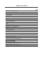
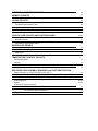
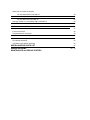
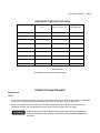
TABLE OF CONTENTS
PAGE
INSPECTION AND UNPACKING
INSTALLATION INSTRUCTIONS
3
3 -12
Installation Policies
3
Basic Assembly
3-5
Installation Clearances
5
Service Connections
6
Electrical
6-7
Water
7
Recommended Plumbing
7 - 11
Water Quality Requirements
7
Drain
12
Start-Up and Check-Out
13
®
INTRODUCTION TO SteamCraft III
Operational Safety
OPERATIONAL FUNCTIONS
13
13
14 -15
Control Panel Overview
14
Setting Digital Time Display
14
"TIMED"-Mode
14
"MANUAL" Mode
15
Special Notes About Control Pane!
15
Thermostatic Timer Compensation
15
UNIT FUNCTIONAL TEST
Before S/N C 1613-88A-24 (with Thermistors)
15 - 17
After S/N C 1613-88A-23 (without Thermistors)
18 - 20
START-UP AND PREHEAT
STEAMING OPERATION
STEAMER TIMER SETTING GUIDE
PREVENTATIVE MAINTENANCE
CHEMICAL DESCALING INSTRUCTIONS
20
20
21
21 - 22
22 - 23
ELECTRICAL CIRCUITRY OVERVIEW
PRIMARY CIRCUITS
Testing of Heating Elements
120 VAC CIRCUITS
24
25
25
26
Water FBI Solenoid Valve
Condenser Water Solenoid Valve
26
26
Contactors: Front- 3-Pole (before S/N C 1613-88A-24)
26
4-Pote (after S/N C 1613-88A-23)
26
Rear- 3-Pole (before S/N C 1613-88A-24)
LOW VOLTAGE CIRCUITS AND CONTROL BOARD
26
27-29
Door Sensor
Membrane Switch
27
30
Compartment Temperature Switch
30
WATER LAVEL PROBES
General Description
30
Flood Probe
31
Water Level
32
Low Water Level
33
TEMPERATURE CONTROL CIRCUITS
General Description
34
Standby
34
Drain Temperature Adjust
Thermistors (on units before S/N C 1613-88A-24)
4
35
EXPLODED-VIEW ASSEMBLY DRAWINGS and PART IDENTIFICATION
Steam Generator. On units before S/N C 2937-88F-14
36
On units after S/N C 2937-88F-13
37
On units after S/N C 5080-88J-00
38-41
Heating Elements
Probes
42-43
44-47
Water Inlet to Steam Generator
On units before S/N C 2937-88F-14
48
On units after S/N C 2937-88F-13
51
On units after S/N C 5519-88L-16
54
Water Inlet to Condenser System:
On units before S/N C 2937-88F-14
49
On units after S/N C 2937-88F-13
52
On units after S/N C 5519-88L-16
55
Drainage System: On units before S/N C 2937-88F-14
50
On units after S/N C 2937-88F-13
53
On units after S/N C 5519-88L-16
56
Electrical Components
57
Front Control Panel
58
Compartment Door and Hinge
59
On units after S/N C 6100-89B-27
60
Door Handle Assembly
62
Door Handle Assembly
63
Cold Water Inlet Strainer Assembly
64
MISCELLANEOUS PARTS LIST
WIRING DIAGRAMS
MAINTENANCE and REPAIR CENTERS
65
66 - 70
Page 3
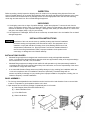
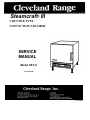
INSPECTION
Before unpacking, visually inspect the shipping carton for evidence of any damage during shipment If there are
signs of possible damage, do not unpack the equipment. Notify the carrier that delivered the shipment so the canon
and its contents can be examined for any damage claims. Fill out all appropriate forms and have the examining
carrier sign and date each form. Do not install damaged equipment
UNPACKING
1. If the shipping carton has no signs of possible damage, unpack the equipment To remove the unit from the
carton, it is easiest to slit the canon in 4 comers and "peel" it away from the steamer. After removing the canon,
examine the steamer for signs of possible damage. If damage exists, detail your observations on a claims form
and give to the shipper (keep a copy for your records).
2. If the equipment is undamaged, lift the unit to the counter top OF stand where it is to be installed. Do not install
damaged equipment
INSTALLATION INSTRUCTIONS
WARNING Installation of this unit mast be done by qualified plumbing and electrical! installation
personnel working to all applicable local and national codes. The equipment is to be
installed to comply with the Basic Plumbing Code of the Building Officials and Code
Administrators International, Inc. (BOCA) and the Food Service Sanitation Manual of
the Food and Drug Administration (FDA). Improper installation of this product could
cause injury or damage and void customer warranty.
INSTALLATION POLICIES:
• Cleveland Range equipment is designed and manufactured to comply with applicable standards
tuners. Included among those certification agencies which have approved the safety of the equipment design
and construction are: UL, NSF, CSA, and others.
•
Cleveland Range equipment is designed and certified for safe operation only when permanently installed in
accordance with local and/or national codes. Many local codes exist, and it is the responsibility of the owner
and installer to comply with these codes.
•
In no event shall Cleveland Range assume any liability damage or injury resulting from installation which are
not in strict compliance with our Installation Instructions. Specifically. Cleveland Range will not
assume any liability for damage or injury resulting from improper installation of equipment, including, but not
limited to temporary or mobile installations.
BASIC ASSEMBLY:
1. The four legs have adjustable feet and should be used to level the unit in both directions: front to rear and side
to side. It is important for good operation that the unit is level.
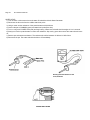
2. Open steamer door and remove package of operational pans. It will contain:
(a) Drain Stopper (Units before S/N C3991-881-01)
(b) 1 Steam Generator Cover
(c) 2 Pan Slide Racks
(d) Water inlet Strainer
Page 4
BASIC ASSEMBLY: (Continued)
CAUTION
DO NOT REMOVE PRE-ASSEMBLED PARTS.
They may be damaged if not handled property.
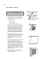
3. Pre-Assembled Parts. When the operating pans
package is removed, several pre-assembled parts
can be seen inside the unit. Do not attempt to
remove these parts.
(d) water level probes
(e) heating elements
(f) compartment drain screen
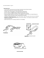
4. Install Drain Stopper (Before S/N C3991-88I-01).
With steamer door open, notice the opening in the
bottom of the compartment. This leads into the
Steam Generator. Inside the Steam Generator
about midway along the left-hand side, you will
find a square shaped fixture with a drilled hole on
top and another on the right side. This is the
Steam Generator drain. Place the Drain Stopper
vertically as shown. Make sure it seats firmly.
5. Install the Steam Generator Cover. This cover is
designed to be installed in only one way. Refer to
illustration (b) in Step 2 above. Using both hands,
lift and locate the cover above the Steam
Generator opening. Lower the cover until it fits
firmly into place.
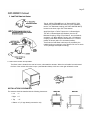
6. Install the Pan Slide Racks. Each slide rack has 4
'loops' which are designed to loop-over' the
stainless steel hanger pins pre-mounted on each
compartment wall Position the 2 upper loops on
the 2 upper hanger pins. Let go. Now place your
hand on bottom of slide rack and gently move the
slide rack upward, allowing top of slide rack to
lean against compartment wall Bottom loops will
easily 'loop-over' bottom hanger pins, Slide rack is
now in position. Pans will slide easily on property
installed slide racks.
7. Check to insure that the Compartment Drain
Screen is free of debris. It is in the left rear comer
of the compartment floor.
Page 5
The 40 - MESH STRAINER and 1/4" Brass NIPPLE (P/N
102383) are preassembled and ready for quick installation
into the 1/4"" Bulkhead Coupling (see COLD WATER INLET)
located on the lower, right rear of the steamer.
Apply Pipe Dope or Teflon Tape to the 1/4" Brass Nipple.
Turn the 1/4" Brass Nipple (and Strainer) into the 1/4"
Bulkhead Coupling. Using a Pipe Wrench, turn the Strainer,
so that the 1/4" Brass Nipple is snug in the 1/4" Bulkhead
Coupling (Cold Water Inlet) and the Strainer is in a vertical
position as shown (with nut in downward position).
Then flush the Cold Water Inlet line (to be provided by the
installer) before connecting it to the Strainer. Be sure to check
.for any leakage and adjust accordingly.
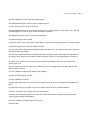
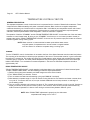
9. Drain Valve Location and Operation.
The Drain Valve is located in the rear left comer, underneath the steamer. When the red handle is turned toward
the front of the unit the drain valve is open. (see illustration below) A 90° turn to the right will dose the valve.
INSTALLATION CLEARANCES:
The steamer should be installed with the following clearances:
• Left
= 2"
• Right = 2"
• Top
= 2"
• Bottom =4" (4" legs already mounted to unit)
Page 6
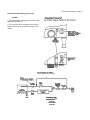
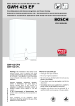
CET-8 Service Manual
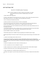
SERVICE CONNECTIONS:
(A) Hole for electrical conduit connection leads to terminal block and
ground connection inside unit. On C.S.A. (Canadian Standards
Association) units 6 feet of flexible electrical conduit is already
attached to the unit for the electrical supply connection.
(B) 1/4" 0 COLD WATER INLET for Steam Generator feed water.
(On units before S/N C 5519-88L-17)
(B) Location for SteamerGard Water Treatment System.
Installation Optional. (On units after S/N C 5519-88L-16)
(C) 1/4" 0 COLD WATER INLET for Condenser feed water.
(On units before S/N C 5519-88L-17)
(C) 1/4" diameter COLD WATER INLET for Steam Generator (Boiler)
feed water and Cold Water Condenser. (On units after S/N C 551988L-16)
(D) Drain (On units after S/N C 2937-88F-13)
ELECTRICAL:
1. Install in accordance with local codes and/or the National Electric Code, ANSINFPA No. 70-1987 (USA) or the
Canadian Electrical Code CSA Standard C22.1 (Canada). A separate fused disconnect switch must be installed
for each unit. The steamer must be electrically grounded by the installer.
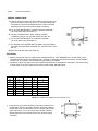
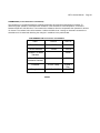
2. The electric supply must match the power requirements specified on the steamer's rating label. The copper wiring
must be sized to carry the required current at the rated voltage. See table below.
VOLTS
SIZE (AWG)
1PH AMPS
SIZE (AWG)
208
KW 3PH AMPS
8.1
23
10
39
8
220
7.4
20
10
34
8
240
8.8
22
10
37
8
380
7.4
12
12
20
10
415
8.8
13
12
22
10
460
7.4
10
14
18
12
480
8.8
11
14
18
12
NOTE: Use copper wire suitable for not less than 75° C
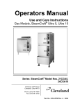
3. Locate the six (6) screws that hold the rear panel to steamer and
remove them. (Save to use again.) Remove rear panel, exposing
the terminal block on bottom panel of unit. Connect with properly
sized copper wire. On C.S.A. units 6 feet of flexible conduit is
already attached to the terminal block for the electrical supply
connection
CET-8 Service Manual
Page 7
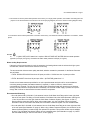
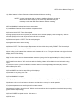
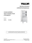
4. The steamer is wired 3 -phase delta operation at the factory. For single phase operation, the installer must change the two
jumpers on the terminal block to that shown in the accompanying diagram (and on the steamer's wiring diagram label).
5. The steamer will be wired 3 phase WYE connection at the factory. For steamers ordered for 380/220 V or 415/240 V, 4 wire 3
phase.
WATER
A 1/4" l.P.S. (M1N. SIZE) COLD water line is required. DO NOT USE HOT WATER. Minimum water pressure
(dynamic) is 35 psi (2.4 kg/cm), the maximum static water pressure is 60 psi (4.1 kg/cm).
Water Quality Requirements
If the purity of the incoming water is good, the generator, the heating element and the valves should give years
of trouble-free, efficient service with a minimum of servicing.
The recommended minimum water quality standards, whether untreated or pretreated. for the Steam Generator
are as follows:
• TOTAL DISSOLVED SOLIDS less than GO parts per million • SILICA less than 13 parts per million
• TOTAL ALKALINITY less than 20 pans per million • pH FACTOR greater than 7.5
Consult a local water treatment specialist for an on-the-premises water analysis and for recommendations
concerning steam generator feed water treatment (if required), in order to remove or reduce harmful
concentrations of minerals. The use of a poor quality (highly mineralized) water will mean that more frequent
servicing of water sensitive components will be necessary. The fact that a water supply is potable is not proof
enough that it will not be detrimental to the water sensitive components.
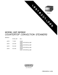
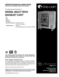
Recommended Plumbing
• On units (before S/N C 5519-88L-17) the steamer has two Cold Water Inlet Fittings at the lower right-hand
side of the rear panel. The fitting on the left feeds the Cold Water Inlet to the Steam Generator (See figures
13 and 16) and the one on the right feeds the Cold Water Condenser System. (See figures 14 and 17)
Decals mark the respective fittings. When using treated water, only the Cold Water Inlet to the Steam
Generator need be connected to the treater; the Cold Water Condenser System can use untreated water.
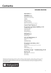
• On units (after S/N C 5519-88L-16) the steamer has one Cold Water Inlet Fitting at the lower right-hand side
of the rear panel (See illustration on page 5). When using a Water Treatment System, the connection for the
Steam Generator (Boiler) is made through the optional hole provided. This process will also require additional parts. The Cold Water Condenser System can use untreated water. (See illustration on page 11). NOTE:
See rear view drawing in "Service Connections, "B & C (page 6).
page 8
CET-8 Service Manual
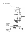
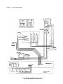
Recommended Plumbing (Continued)
NOTE: This water supply arrangement is used on
units before S/N CS519-88L-17.
TOP VIEW
CET-8 Service Manual
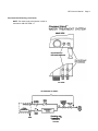
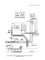
Recommended Plumbing (Continued)
NOTE: This water supply arrangement is used on
units before S/N C5519-88L-17.
TOP VIEW
RECOMMENDED PLUMBING
WATER
TREATMENT
SYSTEM:
Page 9
Page 10
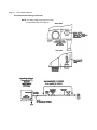
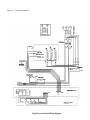
CET-8 Service Manual
Recommended Plumbing (Continued)
NOTE: This water supply arrangement is used
on units before S/N C5519-88L-16.
REAR VIEW
TOP VIEW
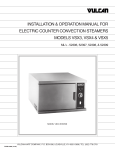
CET-8 Service Manual Page 11
Recommended Plumbing (Continued)
NOTES:
1. This water supply arrangement is used on units
after S/N C5519-88L-16.
WATER TREATMENT SYSTEM
2. The conversion kit for converting one incoming
water line into two for a treatment system is P/N
102431.
RECOMMEMDED PLUMBING
( to be supplied by installers)
WATER
TREATMENT
SYSTEM:
Page 12
CET-6 Service Manual
Drain
This drain line outlet discharges exhaust steam and hot condensate. Connect 1-1/4" I.P.S. piping (or larger) to
extend the drain line to a nearby open floor drain. Up to two elbows and six feet of 1-1/4" I.P.S. (or larger)
extension pipe should be connected to the drain termination. Drain piping extended six to twelve feet. or using
three elbows, should be increased to 2" I.P.S. - DO NOT, UNDER AN CIRCUMSTANCE, CONNECT ANY
OTHER EQUIPMENT DRAIN TO THIS DRAIN LINE. The extension piping must have a gravity flow and vent
freely into the air. This drain outlet must be free vented to avoid the creation of back pressure in the steamer
cooking compartments.
To ensure a vented drain line, DO NOT, UNDER ANY CIRCUMSTANCE, CONNECT THE DRAIN
OUTLET DIRECTLY TO THE FLOOR DRAIN OR SEWER LINE.
Do not run the drain fine discharge into PVC drain piping or any other drain material not capable of sustaining
180°F operation. The equipment is to be installed to comply with the Basic Plumbing Code of the Building Officials
and Code Administrators International, Inc: (BOCA) and the Food Service Sanitation Manual of the Food and Drug
Administration (FDA).
In making a connection to the dram termination use a hardening type of pipe sealant. FINGER TIGHTEN ONLY DO NOT USE A WRENCH.
FAILURE TO OBSERVE THESE REQUIREMENTS CAN RESULT IN DAMAGE TO EQUIPMENT AND/OR THE
POSSIBILTY OF INJURY.
If these instructions are not complied with, there will be steam and water leakage past the
compartment door. Furthermore, the possibility of serious personal injur y may result.
CET-8 Service Manual
Page 13
Start-Up and Check-Out
1. Be sure to put the Steam Generator Cover in its' proper location.
2.
3.
4.
5.
6.
Close Drain Valve.
Turn on water at supply valve.
Turn on electricity at Fused Disconnect Switch.
Close steamer door.
Press "POWER" touch pad.
7. Set Timer display at "01"minutes.
8. Press "TIMED" touch pad. The unit will HI with water and begin to make steam. After the compartment reaches
operating temperature the timer will count down to "00" and an alarm will beep. This test will take 5 to 10
minutes.
9. Press "MANUAL* touch pad. The Heater Elements and the Cold Water Condenser will turn on. Open and dose
the door several times to ensure that the steam shuts off with the door open.
INTRODUCTION TO
To get the full advantage of steam cooking, the Cleveland SteamCraft III must be properly installed. A steamer
which is improperly installed, improperly used, improperly maintained, or improperly repaired will create a
dangerous condition and may cause injury to personnel.
OPERATIONAL SAFETY
Your Cleveland SteamCraft III will require minimum servicing provided it is operated according to instructions and
given the care recommended.
Make sure that responsible personnel understand how your steam cooking equipment should be operated and
cared for. Proper use and maintenance pay handsome dividends in longer equipment He and satisfactory
performance minimal down-time.
Safe steam cooking equipment operation dictates that every owner should follow these rules for operational safety.
1. Begin a comprehersive, continuous program of steam cooking equipment inspection.
2. Never allow untrained personnel to operate your steam cooking equipment. Establish an in-house training
policy and adhere to ft.
3. At the end of each day's operation:
-Shut unit down at the end of each day's operation according to instruction on pages 21 -22.
-Remove any spilled food, then wash the racks and compartment interiors thoroughly with mid detergent in
warm water. Rinse thoroughly with dean warm water. (Racks can be removed and washed in a dishwasher if
desired. To reinstall see Basic Assembly instructions, page 4 .)
Let rinse water drain through compartment drain opening. If water does not drain freely,
drain lines must be cleaned out before cooking again. Clogged or slow drains are
dangerous because hot water may spill out when compartment doors are opened during
or after a cooking cycle.
-Before cleaning the steamer's exterior, BE SURE THAT ELECTRICITY TO THE UNIT AT FUSED
DISCONNECT SWITCH IS OFF. Use a damp cloth for cleaning. Never hose down the equipment.
4. Read and follow Cleveland Range instructions on steamer and steam generator maintenance.
5. Use only replacement parts which are factory authorized to preserve the certification of Underwriters
Laboratories, Canadian Standards Association, and all approvals and to protect your warranty coverage.
6. Never allow unqualified personnel to service your steamer.
Page 14
CET-8 Service Manual
OPERATIONAL FUNCTIONS
Operation of the Cleveland SteamCraft III is very easy. Each operator should become familiar with the
following operational functions and procedures to effectively start, operate, and shut down the steamer.
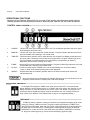
CONTROL PANEL OVERVIEW:—————————————————————————————————————
1.
"POWER"
2.
"MANUAL"
-ON and OFF touch pad controls the power to unit. The red indicator light above the touch •pad is
illuminated when the power is ON.
3.
-ON and OFF touch pad controls the manual operation. The green indicator light above the touch
pad is illuminated when operating in the manual mode.
"TIME SET" -Directional touch pads are used to adjust the time on the DigitaI Time Display located above the
two touch pads. A maximum of 99 minutes can be programmed. The green indicator fight to the
right of the Digital Time Display flashes when the steaming compartment is at steaming
temperature and the time is counting (up or down).
4.
"TIMED"
5.
"FLOOD"
6.
"WATER"
-ON and OFF touch pad controls the timed operation. The green indicator light above the touch pad
is illuminated when operating in the TIMED mode.
-FLOOD is a safety signal. POWER to the unit will automatically turn off when the signal
comes on. Refer to the troubleshooting section when displayed.
-WATER illuminates as the steam generator fills turns off when the water level reaches the
safe operating level.
The touch pad controls are designed to be pressed with finger tips only. Be careful not to use
fingernails, kitchen utensils or anything that could cause damage.
SETTING DIGITAL TIME DISPLAY: —————————————————————————————————————————
————
To set Digital Time Display for TIMED mode, press and hold the "LEFT" touch pad and the
display will begin counting upward from 01 to 10 slowly, then more quickly. Run the time up until
display is dose to (or over) value wanted, then use the "LEFT" and "RIGHT" touch pads to set
actual time desired. Digital time Display must be reset before each new cooking process can
begin. (Refer to the Steamer Timer Setting Guide on page 21 for suggested settings.)
TIMED MODE: ————————————————————————————————————
If TIMED operation is desired, cooking time must be set on Digital time Display. Begin timed
cooking by pressing "TIMED" touch pad. The green indicator light above the "TIMED" touch
pad will become illuminated. When the unit reaches cooking temperature, the timing sequence
will begin and win be confirmed by a flashing green indicator light to the right of the DIGITAL
TIME DISPLAY. At the conclusion of the timed period, the DIGITAL TIME DISPLAY will flash
00. the green indicator light will go out and a 4 second beeping signal win begin.
CET-8 Service Manual
Page 15
OPERATIONAL FUNCTIONS (Continued)
MANUAL MODE:
If TIMED operation is NOT desired, unit may be operated in the MANUAL mode by
pressing the "MANUAL" touch pad which turns the steam flow ON and OFF. The green
indicator light above the "MANUAL" touch pad will be illuminated when unit is ON in the
MANUAL mode. (When operating in the MANUAL mode, the Digital Time Display will start
at 00 and count upward, after the steaming compartment reaches cooking temperature,
keeping actual time lapsed.)
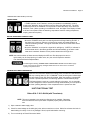
SPECIAL NOTES ABOUT CONTROL PANEL:
• Above the "POWER" touch pad is an alert signal which will begin flashing FLOOD - if
the water level controls or drain are not functioning properly and water threatens to
overflow the steam generator. This signal means the unit has shut off the water and all
other functions.
• Above the "MANUAL" touch pad is a signal which will light up - WATER. It indicates insufficient water level in the steam generator and will automatically go off when a safe
water level is attained. Steamer will not produce steam when this light is on.
NOTE: the event that either of these two-word displays do NOT turn off at the proper time and no
quick remedy can be found (turning of a water valve, etc.) the unit will require the attention
of an Authorized Service Representative.
If FLOOD light is flashing, DO NOT OPEN COMPARTMENT DOOR! Shut off wetter supply
to unit. Flood may be caused by damaged water feed valve. Allow unit to cool before
opening compartment door.
THERMOSTATIC TIMER COMPENSATION:
Whenever this automatic adjustment is taking place, the DIGITAL TIME DISPLAY
will stop counting down (or up if in "MANUAL" mode) and the green indicator light
will stop flashing. Both will remain illuminated. When the steaming compartment
reaches a preset temperature, the steaming operation will automatically begin.
This feature doesn't require any control settings by the owner. It is an automatic
function designed to ensure consistent cooking results whether your food product
is frozen (needing thawed) or if the compartment door is opened too often.
UNIT FUNCTIONAL TEST
Before S/N: C 1613-88A-24 (with Thermistors)
NOTE: This test is intended to be carried out after the unit is installed. If the water,
drain and electrical hook up has been completed property then proceed with
test.
1) Open customer's water supply valve.
2) Check for water leakage at all visible pipe joints, tube connections or unions. Wait a few minutes then look for
water leaking from body of unit. If any leakage is found, repair leaks before continuing.
3) Turn on electricity at Fused Disconnect Switch.
Page 16
CET-8 Service Manual
4) Check to see that front control panel is off and is not illuminated.
5) Short the flood probe (upper most) to generator or ground. "FLOOD" light should begin to flash within three to four
seconds. Push "POWER" touchpad. Unit should not turn on. "FLOOD" light will continue to flash.
6) Turn off electricity to the unit at Fused Disconnect Switch and wait ten seconds. Restore electricity to the unit at
the Fused Disconnect Switch.
7) Close Steam Generator drain by removing Steam Generator Cover and placing drain stopper into opening located
along left hand side.
8) Push "POWER" touchpad on front control panel.
9) Red indicator light above the "POWER" touchpad, digit displays and "WATER" indicator will light.
10) After approximately five seconds, the water fill solenoid will energize and water will begin to fill the Steam Generator.
11) Check for water leakage around the base of the unit.
12) When water level reaches the low water cutoff probe (lowest) the "WATER" indicator will turn off and heater contactor will be energized. One heating element will begin to heat the water in the Steam Generator.
13) With compartment door open, push "MANUAL" touchpad. Green indicator above touchpad
14) Contactor and heater will turn off.
15) Push "MANUAL" touchpad again.
16) Heater turns on and green indicator turns off.
17) As the Steam Generator temperature reaches "standby temperature" the contactor will be de-energized and
heater will turn off.
18) Check that Steam Generator did not come to boil and that water level is correct Water temperature should be
between 180° and 190° degrees F.
19) Push "MANUAL" touchpad. Green indicator above touchpad will light. Close compartment door.
20) When compartment door is dosed the condenser solenoid valve and heater contactors will be energized.
21) Check for water flow from drain. Look for water leakage around base of unit
22) Open compartment door. Condenser water and heaters will turn off.
23) Position a test magnet on top of the control panel enclosure over door sensor. Condenser and heaters will turn
on.
24) Watch heaters in Steam Generator to determine that all three are working.
NOTE: This test is best done with cold water in the Steam Generator so that any
differences in heater output may be more easily detected. It may be necessary
to drain and refill Steam Generator before continuing.
CET-8 Service Manual Page 17
25) Push "MANUAL" touchpad and remove test magnet.
26) Install Steam Generator Cover and close compartment door.
27) Push and hold "LEFT" Time Set touchpad.
28) Digit displays should count up at two per second for first 5 seconds (display of "00" through "10"). After five
seconds displays will count at 20 per second until switch is released.
29) Release and push the "LEFT" Time Set touchpad again.
30) Digits will return to slow counting.
31) Release "LEFT" Time Set touchpad. Repeal steps 27 thru 30 this time pushing "RIGHT" Time Set touchpad.
32) Set time display to "01" and push TIMED" touchpad.
33) As cooking cycle is started the condenser and all heaters will turn on. The green indicator to the right of the
time display will not be flashing.
34) When the compartment reaches operating temperature the green Indicator to the right of the digit displays
win begin to flash. At this time one heater contactor should be cycling on and off approximately once every 5
35) Turner will count down to "00" one minute after the flashing indicator is first lit, this will end the timed
cooking style cycle.
36) At the end of the cycle the heaters and condenser will turn off. the digit displays will flash ("00") and the
alarm will beep four times.
37) Push "TIMED" touchpad to stop flashing of the displays.
38) Set timer to any setting over "00".
39) Push "MANUAL" touchpad.
40) Digit display will reset to "00", heaters and condenser will turn on and green indicator by digit displays will
flash.
41) Allow the unit to run for at least one minute to see that timer counts up in manual operation.
42) Open compartment door carefully Avoid hot steam contact.
43) Steam and condenser should turn off. Within one minute after the door is opened the timer should stop
counting (green indicator stops flashing)
44) Push "POWER" touchpad one time. Unit turns off
45) End of test.
Page 18
CET-8 Service Manual
UNIT FUNCTIONAL TEST
After S/N: C 1613-88A-23 (without Thermistors)
NOTE: This test is intended to be carried out after the unit is installed. If the water,
drain and electrical hook up has been completed property, men proceed
with test.
1) Open customer's water supply valve.
2) Check for water leakage at all visible pipe joints, tube connections or unions. Wait a few minutes then look for
water leaking from body of unit. If any leakage is found, repair leaks before continuing.
3) Turn on electricity at Fused Disconnect Switch.
4) Check to see that front control panel power is off and it is not illuminated.
5) Short the flood probe (upper most) to generator or ground."FLOOD" light should begin to flash within four
seconds. Push "POWER" switch. Unit will not turn on. "FLOOD" light will continue to flash.
6) Turn off electricity to the unit at Fused Disconnect Switch and wait ten seconds. Restore electricity to the unit
Fused Disconnect Switch.
7) Close Steam Generator drain valve by reaching under the unit and pushing the handle to the right. (Units before
serial number C2937-88F-14 have a drain stopper in the generator that must be in place.)
8) Push "POWER" touchpad on front control panel.
9) Red indicator light above the "POWER" touchpad, digit displays and "WATER" indicator will light.
10) After approximately five seconds, the water fill solenoid will energize and water will begin to fill the Steam Generator.
11) Check for water leakage around the base of the unit.
12) If you have removed the front control panel to check for water leakage, make sure ft is up in place and the
compartment door is closed. When water level reaches the low water cutoff probe (lowest) the "WATER" indicator will
turn off and the heater contactor will be energized. The heating elements will begin to heat the water in the Steam
Generator.
13) Open the compartment door and the contactor and heaters will turn off.
14) Close compartment door. Push the "MANUAL" touchpad.
15) When compartment door is dosed the condenser solenoid valve and heater contactors will be energized.
16) Check for water flow from drain. Look for water leakage around base of unit.
17) Open compartment door. Condenser water and heaters will turn off.
18) Position a test magnet on top of the control panel enclosure over door sensor. Condenser and heaters will turn
on.
CET-8 Service Manual
Page 19
19) Watch heaters in Steam Generator to determine that all three are working.
NOTE: This test is best done with cold water in the Steam Generator so that any
differences in heater output may be more easily detected. It may be
necessary to drain and refill Steam Generator before continuing.
20] Push "MANUAL" touchpad and remove test magnet.
21) Install Steam Generator Cover and dose compartment door.
22) Push and hold "LEFT" Time Set touchpad.
23) Digit displays should count up at two per second for first 5 seconds (display of "00" through "10"). After five
seconds displays will count at 20 per second until switch is released.
24) Release and push the "LEFT" Time Set touchpad again.
25) Digits should return to slow counting.
26) Release "LEFT" Time Set touchpad. Repeat steps 22 thru 25 this time pushing "RIGHT" Time Set touchpad.
27) Set time display to Wand push "TIMED" touchpad.
28) As cooking cycle is started the condenser and all heaters will turn on. The green indicator to the right of the time
display should not be flashing.
29) When the compartment reaches operating temperature the green Indicator to the right of the digit displays will
begin to flash. At this time one heater contactor should be cycling on and off approximately once every 5 seconds.
30) Timer will count down to "00" one minute after the flashing indicator is first lit, this win end the timed cooking
cycle.
31) At the end of the cycle the heaters and condenser will turn off, the digit displays will flash ("00") and the
alarm will beep four times.
32) Push TIMED" touchpad to stop flashing of the displays.
33) Set timer to any setting over "00".
34) Push "MANUAL" touchpad.
35) Digit display will reset to "00" heaters and condenser will turn on and green indicator by digit displays will flash.
36) Allow the unit to run for at least one minute to see that timer counts up in manual operation.
37) Open compartment door carefully. Avoid hot steam contact.
38) Steam and condenser should turn off. Within one minute after the door is opened the timer should stop counting
(green indicator stops flashing).
39) Push "POWER" touchpad one time. Unit turns 08.
40) End of test
Page 20
CET-8 Service Manual
START-UP and PREHEAT
1. Be sure the Drain Valve is dosed. Reinstall Steam Generator Cover inside steaming compartment. Drain Screen
must be free of debris.
2. Press the "POWER" touch pad. The red indicator light will become illuminated
indicating that the unit power is ON. Also, the word "WATER" will light up. (Water will
enter the unit, filling the steam generator to proper level, the water flow will cease. The
word •WATER" win stop glowing.)
3. Preheat the Steaming Compartment for at least 5 minutes before beginning steaming operation. This is done by
pressing the "MANUAL" touch pad to turn on the heaters.
STEAMING OPERATION
1.
Preheat steamer compartment (as described in "Start-Up and Preheat").
2.
Slide the pan(s) with food onto the compartment pan slide racks. Close door.
NOTE: To obtain best steaming results, use shallow, perforated pans, without covers. This assures the best
transfer of heat to the food product. When steaming meats, fish or poultry use a catch pan under the
perforated pan to collect the juices. (FAILURE TO USE A CATCH PAN CAN CAUSE A CLOGGED
DRAIN. SEE WARNING NOTE ON PAGE 13).
3. Use either the TIMED" steaming mode or "MANUAL" steaming mode to complete steaming operation.
"TIMED" STEAMING MODE
1. Consult 'Steamer Tuner Setting Guide* for suggested settings (page 21).
2. Set time on timer by pressing the "TIME SET" touch pads.
3. Press the "TIMED" touch pad to start steam flow.
4. Food product is now in process of being cooked. (See note below.)
5. When the selected time has elapsed, the steam flow will automatically turn-off.
6. Remove the pans of food, but be aware that they will be hot. Handle with caution.
"MANUAL" STEAMING MODE
1.
2.
3.
4.
Consult 'Steamer timer Settings Guide' for suggested cooking times (page 21).
Press the "MANUAL" touch pad to start steam flow. The timer will dock up after the initial delay period.
Food product is now in process of being cooked. (See note below.)
To stop the steam flow open the steam door. (If the "MANUAL" touch pad is pressed the timer will dear to "00" and
resume timing.)
5. Remove the pans of food, but be aware that they will be hot. Handle with caution.
*NOTE: Although the steamer door can be opened at any lime during the steaming cycle, the cooking process will
be interrupted because the steam flow will automatically stop when the door is opened and not begin again
until the door is closed. The total cooking time will be lengthened by the amount of time the door is open.
HELPFUL HINT: After steaming operation is over for the day and daily clean-up/maintenance has been performed
as per instruction, leave the steamer door open a little to prolong the life of the door gasket.
CET-8 Service Manual
Page 21
SUGGESTED TIMER SETTING GUIDE
Item
Maximum Amount Per
Pan
Number of Perforated
Pans 12 x 20 x 2 1/2''
Suggested Timer
Setting Minutes
Asparagus Spears
5 Lbs. (2.3 Kg)
1-3
6-9
Broccoli Spears
4 Lbs. (1.8 Kg)
1-3
8-11
Carrots (Whole Baby)
4 Lbs. (1.8 Kg)
1-3
8-11
Corn, Cobbettes
20 Ears
1-3
12-15
Peas, Green
5 Lbs. (2.3 Kg)
1-3
4-7
Hot Dogs
10 Lbs. (10/1)
1*
10
Chicken
5 Lbs. (Cut 8)
1-3*
20
Turkey, Frozen
12 Lbs.
1*
2 1/2 Hrs.
Shellfish
3-4 DOZ .
1-3*
3-8
* (add catch pan)
A Five Minute Preheat Time is Recommended.
PREVENTATIVE MAINTENANCE
DAILY CLEAN-UP
interior:
1. At the end of each day's operation, electricity to the unit should be shut off at the Fused Disconnect Switch and
the steamer compartment door opened allowing the steamer to cool down. Open the drain valve.
2. Remove any spilled food from the steamer, then wash the pan slide rack: drain screen, door gasket, and
compartment interior with mild detergent and warm water. Rinse thoroughly with clear water.
DO NOT use any caustic cleaners awing cleaning procedure. Rinse water should drain freely
through the compartment dram opening. If it does NOT, the drain must be cleaned before using
the steamer.
Page 22
CET-8 Service Manual
DAILY CLEAN-UP (Continued)
3. The pan slide racks are easily removed from the steaming compartment for thorough cleaning. They are stainless
steel and can be washed safely in a dishwasher (See "Basic Assembly," page 4 , to reinstall.)
4. The Steam Generator Cover should be removed only when cool enough to avoid injury. Check to insure that the
water drains freely.
5. Depending on the water quality being used. mineral build-up will vary Refer to Chemical Descaling Procedure,
pages 22-23).
6. Do NOT try to dean the heating elements or water level probes by scraping, brushing, etc. Extensive damage
could result!
Exterior:
1. Always turn off electricity to the unit at Fused Disconnect Switch before using water on the equipment.
2. Do NOT allow water to run into electrical controls
3. Do NOT
hose down
he steamer.
NO HOSES!
4. Allow the steamer to cool before washing. Use the same cleansers and cleaning procedures as for other kitchen
surfaces of stainless steel and aluminum. Mild, soapy water, with a clear water rinse, is recommended.
WEEKLY MAINTENANCE
The steamer is equipped with a drain screen in the back of the cooking compartment. The
steamer should never be operated without the screen in place. This screen. prevents large
food particles from entering and possibly restricting the drain line. Any restriction of the drain
line may cause a slight build-up of back pressure in the compartment resulting in steam leaks
around the door gasket. It also may adversely affect the convection action of the steam in the
compartment which is necessary for optimion performance. Pouring USDA approved drain
cleaner through the compartment drain once a week, will belp to ensure an open drain.
CHEMICAL DESCALING INSTRUCTIONS
PRECAUTIONS:
• Liquid Phosphoric Acid. can be handled with comparitive safety if the basic rules of safety for handling any
acid are followed.
• Breathing the fumes should be avoided. Any areas of the skin with which phosphoric acid comes in contact
should be immediately flushed with large quantities of cold water. Affected clothing should be removed.
• In case of contact with the eyes, the eyes should be flushed with large amounts of cold water for a minimum of
15 minutes, after which, medical attention should be sought.
• Protective goggles are advised, and should be of the approved cup-type. Rubber gloves and a mask to
prevent breathing of dust when handling either the dry product or its solution, are also recommended.
• If accidentally taken internally the person should drink large amounts of water immediately and seek m
attention.
CET-8 Service Manual
Page 23
CLEANING PROCEDURE:
1. Make sure that the steamers' on/off "POWER" touchpad is in the OFF position. Allow ample time for the
compartment and the water in the Steam Generator to cool down before proceeding to step #2.
2. Take the Steam Generator Cover out of the Steam Generator opening.
3. Drain out all of the water present in the Steam Generator by opening the Drain Valve.
4. Remove all loose scale that can be scraped out of the Steam Generator without difficulty and then rinse dean
with tap water. Do not attempt to wash the pieces out through the drain. DO NOT SCRAPE THE HEATING
ELEMENTS OR THE WATER LEVEL PROBES.
5. Close the Drain Valve but leave the Steam Generator Cover out for now.
6. Push the on/off "POWER" touchpad to the ON position. This will allow tap water into the Steam Generator. The
water flow will automatically stop when the normal operating level is reached.
7. Close the cooking compartment door and press the "MANUAL" touch pad to heat the water to 140- 160° F.
8. If the scale on the sides of the Steam Generator extends higher than the water line, add cold tap water
manually (using a container) until the scale is covered with water. The acid works best in water at a temperature
of about 140-160F.
9. Mix two to three cups of phosphoric acid descaler with the hot water in the Steam Generator. A bubbling,
hissing action will be created by the chemical attack of the add on the scale.
10. Replace the Steam Generator Cover on the Steam Generator so the scale on it's surfaces can be removed.
11. Leave the water/acid mixture in the Steam Generator until the metal surfaces have been descaled. The time
required to descale the Steam Generator will vary from a minimum of 1 1/2 hours to several hours, depending on
the quantity of descaling required. As the add is consumed in dissolving the scale, there may still be evidence of
undisolved scale, an additional one or two cups can be added to the working solution.
12. A thorough visual examination of the Steam Generator should reveal that the scale has been removed. When
your inspection is satisfactory, the Steam Generator will be ready to be drained. Simply open the Drain Valve and
let the used cleaning solution drain out. After draining out the used cleaning agent, the Steam Generator will need
to be neutralized to counteract any remaining add.
13. Close the Drain Valve and add three to four tablespoons of baking soda (neutralizing agent) to the Steam
Generator. Set the "TIMED" mode to 10 minutes and push the touch pad to the ON position. A green indicator
light above the touch pad is illuminated when operating in the "TIMED" mode. At the end of the cycle, turn off the
unit at the "POWER" touch pad and open the Drain Valve. Inspect the Steam Generator. If scale exists, repeat
the process; otherwise, descaling is complete.
NOTE: Please contact your Maintenance and Repair Center to purchase Descaling Kits or for information
concerning the descaling procedure.
Page 24
CET-8 Service Manual
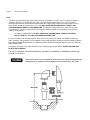
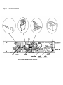
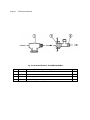
ELECTRICAL CIRCUITRY OVERVIEW
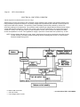
A block diagram for the SteamCraft III is shown in Fig. 1.
SteamCraft III counter type steamers are composed of three separate power systems with interface between each
being handled by relays and contactors. The primary voltage source provided by the customer is used to power all
major power loads in the steamer. The remaining control and display functions are powered by 120 and 18V
secondary windings of the transformer. The contactors used to switch high voltage loads and solenoid valves used to
control water flow are powered by 120 VAC. The control of the 120 volt is carried out by the control board (part #
101606 or 101918). The user input, water level and temperature control, timer functions, time display and safety
circuits are operated on 12 VDC. This regulated DC supply is part of the control board and is powered by 18 VAC.
NOTE: All high voltage (208-480 VAC) input, heater, transformer primary wiring, transformer secondary circuits
(18 and 120 VAC), secondary loads and switching devices (including relay circuits on control boards)
should be isolated from ground.
——288 to 488 volt circuits
------128 volt circuits
——Low voltage control circuits
• on units before S/N C 1613-88A-24
CET-8 Service Manual
Page 25
PRIMARY CIRCUITS
The electrical power input as provided by the customer is used to power heaters and stepdown transformer of the
steamer. These components are affected by the choice of input power in the following ways:
1. Each heater wattage used is available in three design voltages (208,230 and 460 V) Refer to heater data
section below.
2. Primary windings of the stepdown transformer may be series or parallel connected for operation at 208-240 or
440-480 volts respectively.
NOTE: All of the components used in this cooker are designed for use at 50 or
60 Hz. Steamers that are to be run on 50 cycle power must have the
control board modified for that purpose. To do this remove the wire jumper
labeled "JP1". (See figures 2 and 3)
TESTING OF HEATING ELEMENTS:
Disconnect power before checking beating elements
Heating elements may be tested installed in the Steam Generator with or without wiring connected.
Measure resistance of heating dement and compare value to those listed in Table 1 below. It is possible to
determine the actual heater ratings and/or pan number using this method. When trouble-shooting a unit. resistance
between heater terminals and generator tank, (ground) should always be checked. A very high (over 1 Meg ohm) or
infinite resistance should be found between either terminal and ground for dry undamaged heating elements.
CLEVELAND
PART #
DESIGN WATTS VOLTS
OHMS (+/-5%)
101225
2660 208
16
101225-1
2660 230
19
101225-2
2660 460
76
Table 1
Page 26
CET-8 Service Manual
120 VAC CIRCUITS
The acceptable voltage range for the 120 V secondary circuits is 105 to 140 VAC measured no load at the
transformer. For ease of identification all of these circuits are wired with 8 AWG white wire with color stripe or tracer.
All of the wiring is contained in one harness assembly having one, six position plug for connection to the control
board.
Refer to the detailed wiring diagram on page 29 (Fig. 3) and block diagram on page 24.
Control board mounted relays (normally open SPST contacts) are used to switch 120 VAC to water solenoid valves
and heater contactors. Each relay has one side of its contacts connected to a common 120 VAC input. This input is
supplied to the board directly from the stepdown transformer by a wire (white with black stripe) to pin 1 of CON 3. All
120 VAC outputs are also brought out through CON 3. Four outputs are available on control board pan # 101606 and
three available on # 101918. All 120 V loads have one coil connection tied directly to the stepdown transformer via a
single white wire that is 'daisy chained' from coil to coil.
NOTE: If a digital multimeter (DMM) is being used to check voltage output from
CON 3 to solenoids or contactors the load must remain connected to the
board to obtain an accurate result. This is due to the very high input
impedance of this type of meter allows current feeding through the
capacitors across output relay contacts to appear as 120 volts our.
A description of each outputs function is provided below. Refer to wiring diagrams for CON 3 and wiring harness
WATER PILL SOLENOID VALVE:
The water level control for the Steam Generator is active whenever the steamer is on. In normal operation the water fill
solenoid is energized only after the resistance between the middle water probe and the Steam Generator has been
continuously higher than the set point (12,000 Ohm) for more than 5 seconds. When resistance drops below set point
(water touches probe) the solenoid valve is shut off immediately. See Water Level Control section pages 30-33.
CONDENSOR WATER SOLENOID VALVE:
The condensor water solenoid valve is energized during all cooking cycles as long as the compartment
FRONT CONTACTOR (3 POLE) (before S/N C1613-88A-24) or
FOUR POLE CONTACTOR IN (after S/N C 1613-88A-23):
This contactor is energized (heaters on) when the cooking cycle is in progress and the compartment door is closed
AND water level is above the low water probe. ("WATER" light is not lit)
REAR CONTACTOR (3 POLE) (before S/N C 1613-88A-24):
This contactor functions during steaming cycles and in standby operation. When steamer power is on and water is
above low water probe this contactor cycles on and off to maintain water pan temperature at about 190° F. During
steaming cycles (door dosed and water level above tow probe) this contactor cycles on and off to maintain proper
amount of steam in the compartment See Temperature Controls section page 34-35.
CET-8 Service Manual
Page 27
LOW VOLTAGE CIRCUITS and CONTROL BOARD
As seen in the block diagram of the steamer, all sensor and user touchpad inputs are connected directly to the
control board at CON 2 and CON 1 respectively. The control board output connections are provided at CON 3 as
discussed in previous section.
All low voltage DC signals to the control board and the low voltage AC power supply inputs are provided at CON 2 of
the control board. This connector location is provided with an attached wiring harness. Refer to Figure(s) 2 and 3
(Pages 28-29). Color coded pairs of wires are used for thermistor (on units before S/N C 1613-88A-24) and
compartment temperature switch inputs. One wire from each pair is connected to the power supply common. The
water level control probe and power supply common is connected to ground via the green wire from CON 2. All wires
in the harness except the 18 VAC input can be shorted to ground without risk of damage to the steamer. Open or
shorted wiring will cause improper operation of the steamer. See information below for details.
Printed circuit boards used in Cleveland Range equipment are manufactured with conformal type coatings applied
over all components and circuit traces for moisture protection. This coating may be damaged or removed during
handling or shipment. Erratic behavior of a control board often is the result of moisture contamination or snorting
circuit traces. Typically this condition will cause no permanent damage to the control board. In cases where
moisture is suspected cause of failure, the control board should be removed and thoroughly dried. Particular
attention should be paid to connectors and wire leads. After the control board is returned to operating condition,
steps to prevent further contamination should be taken. This may include additional coatings, repair of water leaks or
correction of installation deficiencies.
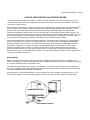
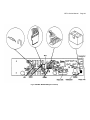
DOOR SENSOR:
Heater contactor(s) and condensor solenoid valve will not operate if door position sensor is not activated. This
sensor is mounted on the Control Board Assembly (pan # 101606,101918 and 101607) and is magnetically activated
by a magnet mounted inside the compartment door.
To test the operation of heater and condensor circuits with the control panel assembly removed or compartment
door open, a magnet may be used to activate the door sensor. The magnet must be positioned over the sensor with
the SOUTH MAGNETIC POLE FACING THE SENSOR.
When replacing a Control Board Assembly it may be necessary to reuse the plastic mounting block. 8-32 x 1/4"
screw and bias magnet. To avoid changing magnet polarity, do not remove the bias magnet from plastic block:
DOOR SENSOR LOCATION
Page 28
CET-8 Service Manual
Fig- 2 CONTROL BOARD PCB (pan # 101606)
CET-8 Service Manual
Fig. 3 CONTROL BOARD PCB (pan # 101918)
Page 29
Page 30
CET-8 Service Manual
MEMBRANE SWITCH: (pan # 101119)
A properly installed membrane switch when tested with an ohm meter must have a resistance of less than 70 ohms
when held closed. This value is as set by the switch vendor for quality control purposes, the design of the circuit is
based on a 5000 ohm limit.
Before testing or replacing a membrane switch be sure that both the pins and sockets of the switch connector (CON 1)
are clean and free of contaminants and moisture. Refer to page 28 and 29 for connector pin location.
COMPARTMENT TEMPERATURE SWITCH: (part # 101543)
A snap action thermostatic switch is attached to the bottom of the compartment near the front left corner of the Steam
Generator. The timer will count (minutes) when this switch is dosed and suspend timing when the switch is open. The
action of the compartment temperature switch provides compensation for product temperature (fresh or frozen),
compartment loading or opening of the compartment door during a cooking cycle.
Problems related to timing of cooking cycles may result from a damaged or improperly installed thermostatic switch. By
removing and jumping together the two purple wires from CON 2 of the control board an accurate check of the timer
operation may be made. If timer still fails count minutes correctly, separate purple wires and check for 12 VDC
between them. Inspect wire leads and terminals if no voltage is detected and repair as required. The thermostatic
switch should be tested to see that ft doses when compartment temperature reaches 180° to 200° F and opens within
two minutes after the compartment (hot) door is open.
WATER LEVEL PROBES
GENERAL DESCRIPTION:
All Cleveland Range steamers employ resistive sensing type water level control circuits. In this a low power AC
current source develops a potential between the shell of the Steam Generator and the sensing probe. When water fills
the tank to the point where the water contacts the probe, current begins to flow (through water) in the circuit. This
current flow is used to trigger an appropriate switching action. For example turning off the water fill solenoid when
current flows in the water level probe circuit.
Current flow through any circuit is a function of both the voltage and the resistance of the circuit In the case of water
level controls the resistance at which the current flow is great enough to cause the control to switch is called the set
point resistance. This is expressed as a nominal DC resistance value and does not take into account the reactive (AC)
characteristics of the water in the circuit. This explains why the measured resistance through water (probe to tank) may
be somewhat higher than the set point resistance of the control without causing any problems.
CET-8 Service Manual
Page 31
The SteamCraft III steamer uses a high frequency (15 to 20 kHz) AC current source with an open circuit voltage of
0.6V RMS ( + /-5%). The nominal set point resistance tor all water level probe functions in these steamers is 12,000
Ohms. This value may vary as much as 5,000 Ohms without significant effect on performance.
To test the operation of water level sensing functions ft. is helpful to have a multimeter or ohmmeter to check
resistance and a 100,000 Ohm potentiometer. Connect the pot between the control board "COMMON" (green wire)
and the appropriate probe wire. Refer to test procedure below for function to be tested.
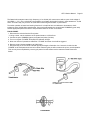
FLOOD PROBE:
1. Disconnect the red wire from the Rood probe
2. Using a meter, set the resistance of the potentiometer to 15,000 Ohms
3. Connect the pot to COMMON (green) and water level probe (red wire)
4. Turn on unit (push "POWER" touchpad) LED indicator will light.
5. Allow one minute of operation to determine if "FLOOD" shut down circuit will be triggered.
6. Remove pot and change resistance to 5,000 Ohms.
7. Reconnect the pot The "FLOOD" indicator light should begin to flash after 3 to 5 seconds. At this time the
"POWER" on/off touchpad should not be functional. Removing the pot will not restore the unit to normal operation.
This can only be accomplished by removing all power from the steamer at the customers Fused Disconnect
Switch.
Reading should be between 5,000
to 18,000 Ohms
FLOOD PROBE
Page 32
CET-8 Service Manual
WATER LEVEL:
1) Turn off water or disconnect wires to the water fill solenoid and drain Steam Generator.
2) Disconnect the blue wire from the middle water level probe
3) Using a meter set the resistance of the potentiometer to 20,000 Ohms
4) Connect the pot to COMMON (green) and water level probe (blue wire)
5) Turn on unit (push "POWER" touchpad) and begin timing. Water level solenoid should energize in 5 to 8 seconds.
6) Slowly turn knob on potentiometer to reduce the resistance. Stop turning pot at the moment the water solenoid turns
off.
7) Remove pot and measure resistance. The resistance should be between 10.000 and 15.000 Ohms.
8) Reconnect the pot. The water solenoid should turn off immediately.
Reading should be between 5.000
to 18,000 Ohms
WATER LEVEL PROBE
CET-8 Service Manual
Page 33
LOW WATER LEVEL:
1) Turn off water or disconnect wires to the water fill solenoid and drain Steam Generator.
2) Disconnect the black wire from the lower water level probe
3) Using a meter set the resistance of the potentiometer to 20,000 Ohms
4) Connect the pot to COMMON (green) and water level probe (black wire)
5) Turn on unit (push "POWER" touchpad) "WATER" warning light should light.
6) With test magnet installed over door sensor, push "MANUAL" touchpad (LED over touchpad will light up).
condenser solenoid valve wit open. Heater contactor(s) will not energize.
7) Slowly turn knob on potentiometer to reduce the resistance. Stop turning pot at the moment the contactor(s}
energize and "WATER" light turns off.
8) Remove pot (contactor turns off immediately) and measure resistance. The resistance should be between
10,000 and 18,000 Ohms.
9) Reconnect the pot. The contactor(s) should turn on immediately.
Reading should be between 5,000 to
18,000 Ohms
LOW WATER PROBE
Page 34
CET-8 Service Manual
TEMPERATURE CONTROL CIRCUITS
GENERAL DESCRIPTION:
Two separate temperature control circuits have been incorporated into the controls of SteamCraft III steamers. These
controls offer the additional standby and power conservation features. Both circuits use a negative temperature
coefficient thermistor (pan # 101508. used on units before S/N C 1613-88A-24) as a temperature sensor and a board
mounted potentiometer for set point adjustment. Each thermistor to control board combination requires separate
calibration, therefore potentiometers must readjusted if a board or thermistor is replaced.
The operation of both the "STANDBY" and the "DRAIN TEMPERATURE ADJUST" circuits make use of the rear heater
contactor to control heater loads. By doing so, the "STANDBY" circuit can turn on one heater (contactor closed) to
preheat water and the "DRAIN TEMPERATURE ADJUST" circuit can turn off (contactor open) two heaters as a means
of steam regulation during cooking cycles.
NOTE: Water must be in contact with the low water probe before heater contactor(s) will operate. Compartment door must be closed or magnet installed
over door sensor for contactors to operate during a cooking cycle.
STANDBY:
For the "STANDBY" control, the thermistor is mounted to the front of the Steam Generator near the water level probes.
The mounting of the thermistor is critical to proper operation of the control. The thermistor must be in good contact with
the surface it is mounted to. This surface should be free of weld spatter or other defects and provided with a thermally
conductive pad or compound. The water preheat temperature may be changed by adjustment of the control board pot
labeled "GEN TEMP". Turn clockwise to increase temperature. Set control so that water temperature is held at
approximately 190°.
DRAIN TEMPERATURE ADJUST:
"DRAIN TEMPERATURE ADJUST" control operation is also dependant on the adjustment of a board mounted potentiometer, labeled "DRAIN TEMP". Use the following procedure to adjust potentiometer.
1) Remove front control panel assembly and install magnet over door sensor location.
2) Turn "DRAIN TEMP" pot clockwise 10 turns.
3) Turn on steamer and start manual steaming cycle (push "MANUAL" touchpad).
4) Allow steamer to operate empty for 15 to 20 minutes. During this time be sure that the rear heater contactor does
not cycle off. If contactor does turn off, turn pot clockwise additional turns to keep contactor on and begin 15
minute waiting period.
5) Turn pot counter clockwise until contactor just turns off. The contactor should begin to cycle on and off. Continue to
adjust pot until the off time period in these cycles is 4 to 6 seconds. Since on/off cycle time will be affected by
water fill solenoid operation it is best to check timing at a time mid-way between water fill cycles.
NOTE: When "DRAIN TEMP" adjustment is properly set, the drain water
temperature will average 150° to 160° F.
CET-8 Service Manual
Page 35
THERMISTORS (on units before S/N C 1613-88A-24):
The resistance of a negative temperature coefficient thermistor will decrease as temperature increases. To
determine proper operation, first measure the resistance of the thermistor at room temperature, it should be
between 90,000 and 125,000 ohms. Then measure the resistence after the compartment has operated for at least
10 minutes. The resistence should be between 10,000 and 25,000 ohms. Leaving an ohmmeter connected to a
thermister as it is heated and observing the changes in resistence is the preferred test.
PART NUMBERS FOR SteamCraft ® III CONTROLS
PART
PART#
PART #
Control Board
101606
101918
120vac Harness
101693
101919
Contactor To heater
Harness
101907
Term. Block to
Contactor Harness
101908
Contactor
101351 2 Req.
101899 1
Req.
Wring Label
101616, 101616A
101616B
TABLE 2
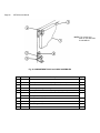
Page 36
CET-8 Service Manual
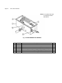
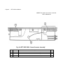
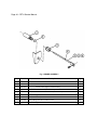
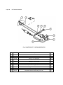
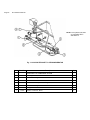
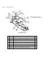
*NOTE: This system was used
on units before S/N C
2937-88F-14
Fig. 4 STEAM GENERATOR ASSEMBLY
Item
Part No.
Description
Qty.
STEAM GENERATOR ASSEMBLY
1
101281
Steam Generator Body
1
2
3
101309
Steam Generator Gasket
1
Heating Element(s ) Assembly (see Fig. 7, pages 42-43)
4
*5
101431
Probe Assembly (see Pig- 8, pages 44-47)
Drain Stopper*
1
CET-8 Service Manual
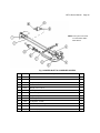
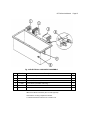
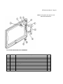
Page 37
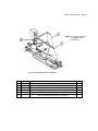
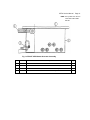
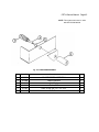
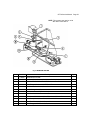
NOTE: This system was used
on units after S/N C
2937-88F-13
Fig.5 STEAM GENERATOR ASSEMBLY
Item
Part No.
Description
Qty.
1
101281
STEAM GENERATOR ASSEMBLY
Steam Generator Body
1
2
101309
Steam Generator Gasket
1
Heating Element(s ) Assembly (see Fig. 7, page 42)
Probe Assembly (see Fig. 9, page 44)
3
Drain Valve Assembly (see Fig. 18, page 53)
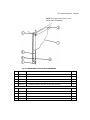
Page 38
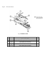
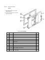
CET-8 Service Manual
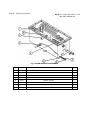
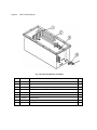
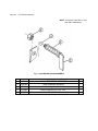
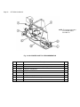
NOTE: This system was used on units
after S/N C 5080-88J-00.
Fig. 6 STEAM GENERATOR ASSEMBLY
Item
Part No.
Description
Qty.
1
102519
Low Water Probe Assembly
1
2
102515
Rood Probe Assembly
1
3
102520
Bulkhead Ground, Wire Assembly
1
4
102518
Water Level Probe Assembly
1
5
23114
Washer, #10 S/S
2
6
14672
Nut, Hex, Lock, Elastic 10-32 Plated
1
7
20323
Terminal, #10 Ring
2
8
102649
Baffle, Rood Probe
1
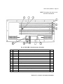
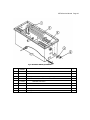
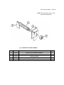
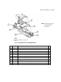
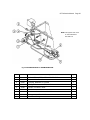
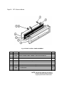
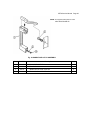
CET-8 Service Manual Page 39
NOTE: This system was used on units
after S/N C 5080-88J-00-
Fig. 6a TOP VIEW - Steam Generator Assembly*
Item
Part No.
1
Description
Qty.
Heating Element Assembly (see voltage required)
101225
2.6 KW, 208 V
3
1012251
2.6 KW, 220 V
3
1012252
2.6 KW, 460 V
3
2
101312
Heating Element Spacer
1
3
14677
Acorn Nut, 1/4-20, S/S
1
4
101306
Sealing Washer, S/S
6
5
101768
Heater Washer, .515 I.D., Zinc PL
6
6
101308
Hex Nut (brass), 1/4-20
6
7
1012781
Probe Baffle
1
8
102515
Rood Probe Assembly (see page 41)
9
102649
Baffle, Rood Probe
1
* Refer to Fig. 6b and 6c for further information.
Page 40
CET-8 Service Manual
NOTE: This system was used on units after
S/N C 5080-88J-00
Fig. 6b LEFT SIDE VIEW - Steam Generator Assembly*
Item
Part No.
Description
Qty.
1
102519
Low Water Probe Assembly
1
2
102518
Water Level Probe Assembly
1
3
102510
Wire, Bulkhead Ground Assembly
1
CET-8 Service Manual
Page 41
NOTE: This system was used on
units after S/N C 508088J-00
Fig. 6c FRONT VIEW Steam Generator Assembly
Item
Part No.
Description
Qty.
1
101402
Steam Generator Gasket
1
2
102257
Steam Generator Weldment Assembly
1
3
102520
Wire, Bulkhead Ground Assembly
1
4
102515
Rood Probe Assembly
1
Page 42
CET-8 Service Manual
Fig. 7 HEATING ELEMENT(S) ASSEMBLY
Item
Part No.
Description
Qty.
HEATING ELEMENT ASSEMBLY
1
101312
2
101225
Bracket Heater Retainer
1
Heating Element Assembly (see Voltage req'd)
3
2666 Watt, 208 V
1012251
2666 Watt, 220-240 V
1012252
2666 Watt, 440-480 V
3
101306
Gasket Washer
6
4
101768
Heating Element Washer
6
5
101308
Heating Element Nut, 1/2" -20
6
CET-8 Service Manual Page 43
Fig. 8 HEATING ELEMENT(S) ASSEMBLY
Item
Description
Part No.
Qty.
HEATING ELEMENT ASSEMBLY
1
101312
2
101225
Bracket Heater Retainer
1
Heating Element Assembly (see Voltage req'd)
3
2666 Watt, 208 V
1012251
2666 Watt, 220-240 V
1012252
2666 Watt, 440-480 V
3
101306
Gasket Washer
6
4
101768
Heating Element Washer
6
5
101308
Heating Element Nut, 1/2"-20
6
Page 44 CET-8 Service Manual
Fig. 9 PROBE ASSEMBLY
Item
Part No.
Description
Qty.
PROBES ASSEMBLY
Probes
3
1
1012961
"Flood" Probe (Upper, shortest Probe)
1
2
101296
"Water" Probe (Middle Probe)
1
3
101296
"Low Water Cut-off" Probe (Lower Probe)
1
4
101302
Probe O-Ring, 5/64" I.D . x 13/64" O.D. x 1/16"
3
5
101316
Probe Nut Ferrule, 1/4"
3
6
101303
Seal, O-Ring, 3/8" I.D. x 1/2" O.D. x 1/16"
3
7
101298
Probe Bushing
3
CET-8 Service Manual Page 45
NOTE: This system was used on units
after S/N C 5080-88J-00.
Fig. 10 FLOOD PROBE ASSEMBLY
Item
Part No.
Description
Qty.
1
2
3
4
5
6
102515
101298
1013161
1012954
101303
102649
FLOOD PROBE ASSEMBLY
Ribbed Insulator
Nut, Probe
Probe, S/S
Seal, O-ring 3/8" I.D. x 1/2" O.D.
Baffle
1
1
1
1
1
1
Page 46
CET-8 Service Manual
NOTE: This system was used on units
after S/N C 5080-88J-00.
Fig. 11 LOW WATER PROBE ASSEMBLY
Item
Part No.
Description
Qty.
1
2
3
4
5
102519
1022532
102236
1013023
102254
LOW WATER PROBE ASSEMBLY
Probe Weldment Assembly
Bushing, Insulator
Seal, O-ring 5/8" I.D. x 3/4" O.D.
Nut, Hex 5/8"-11 Nylon
1
1
1
1
1
CET-8 Service Manual
Page 47
NOTE: This system was used on units
after S/N C 5080-88J-00.
Fig. 12 WATER LEVEL PROBE ASSEMBLY
Item
Part No.
Description
Qty.
1
102518
WATER LEVEL PROBE ASSEMBLY
1
2
1022532
Probe Weldment Assembly
1
3
102236
Bushing, Insulator
1
4
1013023
Seal, O-ring 5/8" I.D. x 3/4" O.D.
1
5
102254
Nut, Hex 5/8"-11 Nylon
1
Page 48
CET-8 Service Manual
Fig. 13 WATER INLET TO STEAM GENERATOR
Item
Part No.
Description
Qty.
WATER INLET TO STEAM GENERATOR
1
101775
Incoming Water Connection, Fitting 1/4", Bulkhead
1
2
102486
Tubing 1/4", Polyethylene
(per ft.)
3
22218
Water Solenoid Valve
1
4
06214
Fitting 90°, 1/4" T x 1/8" P
1
5
102486
Tubing 1/4'', Polyethylene
(per ft.)
6
06190
Compression Fitting, 1/4" T x 1/8" P
1
7
101674
Pitting, Steam Generator Inlet
1
8
1013022
O-Ring
1
9
101307
Nut, Steam Generator Intet Fitting 7/16" x 20
1
CET-8 Service Manual
Page 49
NOTE: This system was used
on units before S/N C
2937-88F-14
Fig. 14 WATER INLET TO CONDENSER SYSTEM
Item
Part No.
Description
Qty.
WATER INLET TO CONDENSER SYSTEM
1
101775
Incoming Water Connection, Fitting 1/4", Bulkhead
2
102486
Tubing 1/4", Polyethylene
1
3
22218
Water Solenoid Valve
1
4
05214
Fitting 90°. 1/4" T x 3/8" P
1
5
101774
1/4" Tubing Insert
6
14661
1/4" Tube rating Nut
7
102486
Tubing 1/4", Polyethylene
8
06193
Tube Fitting, 1/4" T x 3/8" P
2
9
15463
Row Regulator, 1/4 GPM
1
10
06190
1/8 -1/4 Compression Fitting
11
101258
Condenser Fitting
12
14556
Condenser Spray Nozzle
(per ft.)
(per ft.)
1
Page 50
CET-8 Service Manual
NOTE: This system was
used on units before
S/N C 2937-88F-14
Fig. 15 DRAINAGE SYSTEM
Item
Part No.
Description
Qty.
DRAINAGE SYSTEM
1
101735
Inner Drain Screen (should be welded in place)
1
2
101431
Drain Stopper (see note above)
1
3
08505125
0
1017461
Drain Hose (see note above)
1
Drain Assembly (see note above)
1
4
CET-8 Service Manual
Page 51
NOTE: This system was used
on units after S/N C
2937-88F-13
-- ( Not shown, see fig. 13)
Fig. 16 COLD WATER INLET TO STEAM GENERATOR
Item
Part No.
Description
Qty.
WATER INLET TO CONDENSER SYSTEM
1
101775
Incoming Water Connection, Fitting 1/4", Bulkhead
2
1024862
3
22218
Water Solenoid Valve
1
4
06214
Fitting 90°, 1/4" T x l/8" P
1
5
1024861
Tubing 1/4", Polyethylene
18"
6
06190
Compression Fitting, 1/4"T x l/8" P
1
7
101674
Fitting, Steam Generator Inlet
1
8
1013022
O-Ring
1
9
101307
Nut, Steam Generator Inlet Fitting 7/16" x 20
1
Tubing 1/4", Polyethylene
1
24"
Page 52
CET-8 Service Manual
NOTE: This system was used
on units after S/N C
2937-88F-13
Fig. 17 COLD WATER INLET TO STEAM GENERATOR
Item
Part No.
Description
Qty.
WATER INLET TO CONDENSER SYSTEM
1
101775
Incoming Water Connection
2
1024862
3
22218
Condenser Solenoid Valve 1/4", 120V
1
4
06214
1/4" Tube 90° Compression Fitting. 1/4" MPT
1
5
1024862
6
06231
Fitting, 1/4" tube x 1/8" FPT, 90° Brass
1
7
14497
Nozzle, Condenser. Brass
1
Condenser Tubing
Condenser Tubing
1
24-
24"
CET-8 Service Manual Page 53
NOTE: This system was used on units
after S/N C 2937-88F-13.
Fig. 18 DRAINAGE SYSTEM
Item
Part No.
102030
Description
Qty.
DRAINAGE SYSTEM
1
101735
Inner Drain Screen (should be welded in place)
1
2
101970
3
06231
Fitting. 1/4" tube x 1/8" FPT, 90° Brass
1
4
14497
Nozzle, Condenser, Brass
1
5
1024862
6
22243
7
222431
8
085250500
9
03206
Clamp, Hose, Worm Drive, 1/2" x 29/32" dia.
2
10
20230
Tee - Black,1-l/4" x 1/2" x 1-1/4"
1
11
06249
Fitting, 1/2" MPT x 5/8" I.D., Hose
1
COMPARTMENT DRAIN ASSEMBLY
24" long tube 1/4"
24"
Valve, Ban, 1/2" (Drain Valve)
1
Drain Valve Handle
1
Hose, 5/8" O.D. x 1/16" w., Translucent Silicone Rubber
Page 54
CET-8 Service Manual
NOTE: This system was used
on units after S/N C
5519-88L-16
Fig. 19 COLD WATER INLET TO STEAM GENERATOR
Item
Part No.
Description
Qty.
COLD WATER INLET TO STEAM GENERATOR
1
Hole, location for Water Treatment System (optional)
2
1024862
Tubing 1/4", Polyethylene
24"
3
22218
Water Solenoid Valve
1
4
06214
Pitting 90°, 1/4" T x l/8" P
1
5
1024861
Tubing 1/4", Polyethylene
18"
6
102520
Bulkhead Ground, Wire Assembly
1
7
102424
Duckbill
1
CET-8 Service Manual Page 55
NOTE: This system was used
on units after S/N C
5519-88L-16
Fig. 20 COLD WATER INLET TO STEAM GENERATOR
Item
Part No.
Description
Qty.
COLD WATER INLET TO STEAM GENERATOR
1
06188
Tee, 1/4" Male Run, Brass
1
2
03641
Coupling, Bulkhead 1/4" Female
1
3
06231
Fitting, 1/4" tube x 1/8" FPT, 90° Brass
1
4
14497
Nozzle. Condenser, Brass
1
5
102424
Duckbill
1
6
22218
Condenser Solenoid Valve 1/4" 120V
2
7
06214
Fitting, 90°. 1/4" T x 1/8" P
1
8
1024862
Condenser Tubing
24"
Page 56
CET-8 Service Manual
NOTE: This system was used on
units after S/N C 2937-88F-13
Fig.2 1 DRAINAGE SYSTEM
Item
Part No.
Description
Qty.
DRAINAGE SYSTEM
1
1017352
2
102030
3
102424
4
Inner Drain Screen (should be welded in place)
1
DRAIN VALVE ASSEMBLY
Duckbill
1
06231
Fitting. 1/4" tube x 1/8" FPT, 90° Brass
1
5
14497
Nozzle. Condenser, Brass
1
6
1024862
7
22243
Valve, Ball, 1/2" (Drain Valve)
1
8
03206
Clamp, Hose, - lined worm drive, 1/2" x 29/32" dia.
2
9
085300500
Tubing, Braided - 5.00" length
5"
24" long tube 1/4"
24"
CET-8 Service Manual
Page 57
Fig. 22 ELECTRICAL COMPONENTS ASSEMBLY
Item
Part No.
Description
1
101352
Terminal Block 4 pole*
1
2
101640
150 V.A. Step Down Transformer *
1
3
101899
Contactor, 120 V, 50/60 cycle *
1
4
19980
Thermoswitch (Canadian Units Only) **
1
5
101543
Snap Disc Thermoswitch ***
1
6
102286
Contactor, Varistor 276-568 ****
1
* Mounted to Base Plate.
**Mounted to Steam Generator (Prior to CSA Approval).
***Mounted to cooking compartment bottom.
**** Mounted terminal to terminal on contactor coil.
Qty.
Page 58
CET-8 Service Manual
Fig. 23 FRONT CONTROL PANEL ASSEMBLY
Item
Part No.
Description
1018743
FRONT CONTROL PANEL ASSMBLY - After S/N 6790-89E-05
101874
FRONT CONTROL PANEL ASSMBLY - Before S/N 6790-89E-04
Qty.
1
1012921
Front Panel Weldment
1
2
101944
Front Panel Gasket
1
3
1019301
Membrane Switch Assembly
1
4
101606
Control Panel PCB
1
5
101684
Compartment Door Sensor bias Magnet, 1/4"
1
6
101710
Compartment Door Sensor bias Magnet Bracket
1
7
14598
8 x 32 hex nut
12
8
23148
# 8 nylon washer
18
NOTE: Nuts and/or washers are used to
maintain adequate space between
support panel and control board.
CET-8 Service Manual Page 59
NOTE: This system was used on units
before S/N C 6100-89B-27.
Fig. 24 COMPARTMANT DOOR AND HINGE ASSEMBLIES
Item
Part No.
Description
Qty.
DOOR ASSEMBLY, COMPARTMENT
1
101772
2
101237
Door Gasket
1
3
101299
Nylon, Ranged Bushing
2
1017721
Compartment Door Assembly, hinged l eft (standard)
Compartment Door Assembly, hinged right (optional)
1
1
COMPARTMENT DOOR HINGE ASSEMBLY
4
101269
Compartment Door Hinge Bracket
1
5
101334
10 x 32 Pan Head Screw
2
6
101259
7
101270
Compartment Door Hinge Rod
10 x 32 x 1/2" Hex Head Screw
1
1
Page 60
CET-8 Service Manual
NOTE: This system was
used on units after S/N
C 6100-89B-27
Fig. 25 COMPARTMENT DOOR and HINGE ASSEMBLIES
Item
Part No.
Description
Qty.
COMPARTMENT DOOR ASSEMBLY
1
101772
2
101237
Door Gasket
1
3
101299
Nylon, Flanged Bushing
2
1017721
Compartment Door Assembly, hinged left (standard)
Compartment Door Assembly, hinged right (optional)
1
1
COMPARTMENT DOOR HINGE ASSEMBLY
102000
Hinge Assembly, Top Left
101998
Hinge, Door, Top Left
102001
Hinge Assembly, Bottom Left
5
101999
Hinge, Door, Bottom Left
1
6
102129
Screw. 1/4"-28 x 1/2" Hex HD S/S
4
4
1
CET-8 Service Manual Page 61
NOTE: This system was used on units
before S/N 6790-89E-04.
Fig. 26 DOOR HANDLE AND LATCH ASSEMBLIES
Item
1
2
3
4
5
6
7
8
9
Part No.
101277
101284
101873
101255
101260
101334
101253
101256
23116
Description
DOOR HANDLE and LATCH ASSEMBLIES
Handle, Door Assembly
Washer, Teflon, Door Handle
Nut, 1/4"-20 Hex elastic lock
Nut, Spring
Spring, Door Latch
Screw # l0-32 x 1/2" Slotted Pan Head S/S
Nut, Jam, Door Strike Pin 3/8-24
Strike Pin, Door
Washer
Qty.
1
4
2
1
1
1
1
1
2
Page 62
CET-8 Service Manual
NOTES:
1. This system was used on units after
S/N 6790-89E-05.
2. All units with this style door use control
panel P/N 1018743.
Fig. 27 DOOR ASSEMBLY
Item
Part No.
Description
Qty.
DOOR ASSEMBLY
1
102240
Hinged Left
1022401
Hinged Right
1
OUTER DOOR
1
102237
Hinged Left
1022371
Hinged Right
1
INNER DOOR
2
102239
Hinged Left and Hinged Right
1
3
102231
Handle
1
102000
4
101998
HINGE ASSEMBLY, TOP LEFT
Hinge, Door, Top Left
1
102001
HINGE ASSEMBLY, BOTTOM LEFT
5
101999
Hinge, Door, Bottom Left
1
6
101237
Door Gasket
1
CET-8 Service Manual Page 63
NOTE: This system was used on units
after S/N 6790-89E-05.
Fig. 28 HANDLE AND LATCH ASSEMBLY
Item
Part No.
1
102231
2
102241
3
23114
4
101334
Description
DOOR HANDLE ASSEMBLY
Qty.
1
Door Striker
1
Washer #10-Int Tooth Lock S/S
2
Screw *10-32 x 1/2 S/S Pan Head
2
Page 64
CET-8 Service Manual
Fig. 29 COLD WATER INLET STRAINER ASSEMBLY
Item
Part No.
102383
Description
COLD WATER INLET STRAINER ASSEMBLY
Qty.
1
1
19870
Strainer, 1/4"
1
2
03641
Coupling, Bulkhead 1/4" Female
1
3
06188
Tee, Tubing Male Fitting
1
CET-8 Service Manual
Miscellaneous Parts List
Description
Number
Steam Generator Cover Assembly
101288
Pan Racks
414231
Wire Harness:
Terminal Block to Contactor
101908
Contactor to Heater
101907
Control Circuit
101919
Leg, 4"
101450
Page 65
Page 66
CET-8 Service Manual
Fig-30 With 2 Thermistors and 2 Contactors
CET-8 Service Manual Page 67
Fig. 31 With No Thermistors and 2 Contactors
Page 68
CET-8 Service Manual
Fig. 32 With No Thermistors and 1 Contactor
•(For Current Domestic Production)
CET-8 Service Manual Page 69
Fig. 33 With No Thermistors, 1 Contactor, 1 High Limit Thermostatic Switch
(Canadian Units Only)
Page 70
CET-8 Service Manual
Fig.34 Current Export Wiring Diagram