1
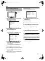
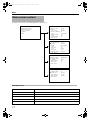
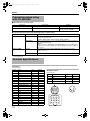
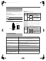
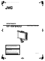
VF-HP840U_EN.book Page 1 Thursday, January 17, 2008
2:48 PM
VIEWFINDER
VF-HP840U
INSTRUCTIONS
Thank you for purchasing this JVC product.
Before beginning to operate this unit, please read
the instructions carefully to ensure the best
possible performance.
For Customer Use:
Enter below the Serial No. which is located on the
body.
Retain this information for future reference.
Model No.
Serial No.
LST0662-001B
VF-HP840U_EN.book Page 2 Thursday, January 17, 2008
2:48 PM
Getting Started
FOR USA
These are general IMPORTANT SAFEGUARDS and certain items may not apply to all appliances.
IMPORTANT SAFEGUARDS
1.
2.
3.
4.
Read all of these instructions.
Save these instructions for later use.
All warnings on the product and in the operating instructions should be adhered to.
Unplug this appliance system from the wall outlet before cleaning. Do not use liquid cleaners or aerosol
cleaners. Use a damp cloth for cleaning.
5. Do not use attachments not recommended by the appliance manufacturer as they may cause hazards.
6. Do not use this appliance near water - for example, near a bathtub, washbowl,kitchen sink, or laundry tub, in a wet
basement, or near a swimming pool, etc.
7. Do not place this appliance on an unstable cart, stand, or table. The appliance may fall,
PORTABLE CART WARNING
(symbol provided by RETAC)
causing serious injury to a child or adult, and serious damage to the appliance.
Use only with a cart or stand recommended by the manufacturer, or sold with the appliance.
Wall or shelf mounting should follow the manufacturer's instructions, and should use a
mounting kit approved by the manufacturer. An appliance and cart combination should be
moved with care.
Quick stops, excessive force, and uneven surfaces may cause the appliance and cart
S3125A
combination to overturn.
8. Slots and openings in the cabinet and the back or bottom are provided for ventilation, and to insure reliable operation of
the appliance and to protect it from overheating, these openings must not be blocked or covered. The openings should
never be blocked by placing the appliance on a bed, sofa, rug, or other similar surface.
This appliance should never be placed near or over a radiator or heat register.
This appliance should not be placed in a built-in installation such as a bookcase unless proper ventilation is provided.
9. This appliance should be operated only from the type of power source indicated on the marking label. If you are not sure
of the type of power supplied to your home, consult your dealer or local power company. For appliance designed to
operate from battery power, refer to the operating instructions.
10. For added protection for this product during a lightning storm, or when it is left unattended and unused for long periods
of time, unplug it form the wall outlet and disconnect the antenna or cable system. This will prevent damage to the
product due to lightning and power-line surges.
11. Do not allow anything to rest on the power cord. Do not locate this appliance where the cord will be abused by persons
walking on it.
12. Follow all warnings and instructions marked on the appliance.
13. Do not overload wall outlets and extension cords as this can result in fire or electric shock.
14. Never push objects of any kind into this appliance through cabinet slots as they may touch dangerous voltage points or
short out parts that could result in a fire or electric shock. Never spill liquid of any kind on the appliance.
15. Do not attempt to service this appliance yourself as opening or removing covers may expose you to dangerous voltage
or other hazards. Refer all servicing to qualified service personnel.
16. Unplug this appliance from the wall outlet and refer servicing to qualified service personnel under the following conditions:
a. When the power cord or plug is damaged or frayed.
b. If liquid has been spilled into the appliance.
c. If the appliance has been exposed to rain or water.
d. If the appliance does not operate normally by following the operating instructions. Adjust only those controls that
are covered by the operating instructions as improper adjustment of other controls may result in damage and will
often require extensive work by a qualified technician to restore the appliance to normal operation.
e. If the appliance has been dropped or the cabinet has been damaged.
f. When the appliance exhibits a distinct change in performance - this indicates a need for service.
17. When replacement parts are required, be sure the service technician has used replacement parts specified by the
manufacturer that have the same characteristics as the original part. Unauthorized substitutions may result in fire,
electric shock, or other hazards.
18. Upon completion of any service or repairs to this appliance, ask the service technician to perform routine safety checks
to determine that the appliance is in safe operating condition.
2
VF-HP840U_EN.book Page 3 Thursday, January 17, 2008
2:48 PM
Safety Precautions
INFORMATION (FOR CANADA)
RENSEIGNEMENT (POUR CANADA)
This Class A digital apparatus complies with Canadian ICES-003.
FOR USA AND CANADA
Cet appareil num rique de la Classe A est conforme á la norme
NMB-003 du Canada.
CAUTION
RISK OF ELECTRIC SHOCK
DO NOT OPEN
CAUTION: TO REDUCE THE RISK OF ELECTRIC
SHOCK. DO NOT REMOVE COVER (OR
BACK).
NO USER-SERVICEABLE PARTSINSIDE.
REFER SERVICING TO QUALIFIED
SERVICE PERSONNEL.
The lightning flash wish arrowhead symbol,
within an equilateral triangle is intended to
alert the user to the presence of uninsulated
"dangerous voltage" within the product's
enclosure that may be of sufficient magnitude
to con-stitute a risk of electric shock to
persons.
The exclamation point within an equilateral
triangle is intended to alert the user to the
presence of important operating and
maintenance (servicing) instructions in the
literature accompanying the appliance.
Information for USA
INFORMATION:
This equipment has been tested and found to comply with
the limits for a Class A digital device, pursuant to Part 15 of
the FCC Rules.
These limits are designed to provide reasonable protection
against harmful interference when the equipment is
operated in a commercial environment.
This equipment generates, uses, and can radiate radio
frequency energy and, if not installed and used in
accordance with the instruction manual, may cause harmful
interference to radio communications.
Operation of this equipment in a residential area is likely to
cause harmful interference in which case the user will be
required to correct the interference at his own expense.
CAUTION:
CHANGES OR MODIFICATIONS NOT APPROVED BY JVC
COULD VOID USER fS AUTHORITY TO OPERATE THE
EQUIPMENT.
NOTE:
WARNING:
TO REDUCE THE RISK OF FIRE OR ELECTRIC
SHOCK, DO NOT EXPOSE THIS APPLIANCE TO RAIN
OR MOISTURE.
This unit should be used with 12V DC only.
CAUTION:
To prevent electric shocks and fire hazards, do NOT use any
other power source.
AVERTISSEMENT:
POUR EVITER LES RISQUES
D'INCENDIE OU D'ELECTROCUTION, NE PAS
EXPOSER L'APPAREIL A L'HUMIDITE OU A LA
PLUIE.
Ce magnétoscope ne doit être utilisé que sur du courant
direct en 12V.
ATTENTION:
Afin d’eviter tout resque d’incendie ou d’electrocution, ne
pas utillser d’autres sources d’alimentation électrique.
NOTE:
The rating plate (serial number plate) is on the side of the unit.
REMARQUE:
La plaque signalétique (plaque du numéro desérie) est située sur
le cadre inférieur de l’unité.
CAUTION:
To prevent electric shock, do not open the cabinet. No user
serviceable parts inside. Refer servicing to qualified service
personnel.
Due to design modifications, data given in this instruction book
are subject to possible change without prior notice.
The apparatus shall not be exposed to dripping or splashing and
that no objects filled with liquids, such as vases, shall be placed
close to the apparatus.
The rating plate (serial number plate) is on this unit.
WARNING:
TO REDUCE THE RISK OF FIRE OR ELECTRIC SHOCK,
DO NOT EXPOSE THIS APPLIANCE TO RAIN OR
MOISTURE.
THIS DEVICE COMPLIES WITH PART 15 OF THE FCC
RULES.
OPERATION IS SUBJECT TO THE FOLLOWING TWO
CONDITIONS: (1) THIS DEVICE MAY NOT CAUSE
HARMFUL INTERFERENCE, AND (2) THIS DEVICE MUST
ACCEPT ANY INTERFERENCE RECEIVED, INCLUDING
INTERFERENCE THAT MAY CAUSE UNDESIRED
OPERATION.
IMPORTANT RECYCLING INFORMATION
This product has a fluorescent lamp that contains
mercury. Disposal of these materials may be
regulated in your community due to environmental
considerations. For disposal or recycling
information, please contact your local authorities
or for USA, the Electronics Industries Alliance:
http://www.eiae.org.
This unit should be used with 12 V DC only.
3
VF-HP840U_EN.book Page 4 Thursday, January 17, 2008
2:48 PM
Getting Started
Safety Precautions
(continued)
Information for Users on Disposal of Old Equipment
[European Union]
FOR EUROPE
This equipment is in conformity with the provisions and protection
requirements of the corresponding European Directives. This
equipment is designed for professional video appliances and can
be used in the following environments:
R Controlled EMC environment (for example, purpose-built
broadcasting or recording studio), and rural outdoors
environments.
In order to keep the best performance and furthermore for
electromagnetic compatibility we recommend to use cables not
exceeding the following lengths:
Attention:
This symbol isonly valid in the European
Union.
Where there are strong electromagnetic waves or magnetism, for
example near a radio or TV transmitter, transformer, motor, etc.,
the picture and the sound may be disturbed. In such case, please
keep the apparatus away from the sources of the disturbance.
This symbol indicates that the electrical and electronic
equipment should not be disposed as general household
waste at its end-of-life. Instead, the product should be handed
over to the applicable collection point for the recycling of
electrical and electronic equipment for proper treatment,
recovery and recycling in accordance with your national
legislation.
By disposing of this product correctly, you will help to conserve
natural resources and will help prevent potential negative
effects on the environment and human health which could
otherwise be caused by inappropriate waste handling of this
product. For more information about collection point and
recycling of this product, please contact your local municipal
office, your household waste disposal service or the shop
where you purchased the product. Penalties may be applicable
for incorrect disposal of this waste, in accordance with national
legislation.
Dear Customer,
(Business users)
Cable
Maximum Cable
Length
VF CABLE
Shield Cable
0.58 m
DC CABLE
Shield Cable
5m
RETURN VIDEO
Shield Cable
5m
Caution:
This apparatus is in conformance with the valid European directives and
standards regarding electromagnetic compatibility and electrical safety.
European representative of Victor Company of Japan, Limited is:
JVC Technology Centre Europe GmbH
Company name changed in:
JVC Technical Services Europe GmbH
Postfach 10 05 52
61145 Friedberg
Germany
Sehr geehrter Kunde, sehr geehrte Kundin,
dieses Gerät stimmt mit den gültigen europäischen Richtlinien und
Normen bezüglich elektromagnetischer Verträglichkeit und
elektrischer Sicherheit überein.
Die europäische Vertretung für die Victor Company of Japan,
Limited ist:
JVC Technology Centre Europe GmbH
Firmenname geändert in:
JVC Technical Services Europe GmbH
Postfach 10 05 52
61145 Friedberg
Deutschland
4
If you wish to dispose of this product, please visit our web
page www.jvceurope.com to obtain information about the
take-back of the product.
[Other Countries outside the European Union]
If you wish to dispose of this product, please do so in
accordance with applicable national legislation or other rules
in your country for the treatment of old electrical and
electronic equipment.
VF-HP840U_EN.book Page 5 Thursday, January 17, 2008
2:48 PM
Table of Contents
Features
This product is an 8.4-inch color viewfinder for use in the GYHD250U/KA-HD250U studio system.
Getting Started
Safety Precautions . . . . . . . . . . . . . . . . . . . . . . . . . .
Table of Contents . . . . . . . . . . . . . . . . . . . . . . . . . . .
Features . . . . . . . . . . . . . . . . . . . . . . . . . . . . . . . . . .
Precautions During Use . . . . . . . . . . . . . . . . . . . . . .
Names and Functions of Parts . . . . . . . . . . . . . . . . .
3
5
5
6
7
High Resolution
This is a large viewfinder with an 8.4-inch XGA (1024 x 768)
LCD panel.
Multi Scan
Setup
Installation . . . . . . . . . . . . . . . . . . . . . . . . . . . . . . . . 9
Mounting on KA-HD250U ...................................... 9
Connecting VF cable ............................................. 9
Mounting hood cover (provided) .......................... 10
Adjusting position . . . . . . . . . . . . . . . . . . . . . . . . . . 10
Outputting images . . . . . . . . . . . . . . . . . . . . . . . . . 10
Adjusting picture quality . . . . . . . . . . . . . . . . . . . . . 10
Return Video Input Terminal
This product is equipped with a return video input terminal and
allows composite signals and HD component (Y signals only)
input.
Rich Marker
Menu
Menu Setting Method . . . . . . . . . . . . . . . . . . . . . . . 11
Entering camera name ........................................ 11
Returning menu settings to default settings ......... 11
Menu screen content . . . . . . . . . . . . . . . . . . . . . . . 12
MAIN MENU Screen ............................................ 12
MARKER SETTING Menu Screen ...................... 13
SHOOTING ASSIST Menu Screen ..................... 14
VIDEO FORMAT Menu Screen ........................... 15
OTHERS Menu Screen ....................................... 15
The product is installed with the Safety Zone display, two types
of Zebra display and the Focus Assist function, all of which are
highly useful in the studio.
Screen Menu Function
The menu is displayed on the screen and you can set or adjust
the most appropriate monitor settings for the connected system.
How to read this manual
Others
Precautions when using with GY-HD250U . . . . . . .
Terminal Specifications . . . . . . . . . . . . . . . . . . . . .
Setting Selection DIP Switch . . . . . . . . . . . . . . . . .
Troubleshooting . . . . . . . . . . . . . . . . . . . . . . . . . . .
Specifications . . . . . . . . . . . . . . . . . . . . . . . . . . . . .
Supports YPbPr (RGB) input of HD (1080i 50/60, 720p 50/60)
and SD (480i 60, 576i 50). (For RGB, only SD is supported)
16
16
17
17
18
䡵 Definition of Symbols
Caution : Precautions that need to be taken during operation
Note
: Details for reference, such as features and
restrictions during use.
A
: Page or item to refer to.
䡵 Descriptions in this manual
● The copyright of this manual belongs to Victor Company of
Japan, Limited. Reproduction or duplication of a part or the
whole of this manual without permission is prohibited.
● Product names of other companies contained in this
manual are the trademark or registered trademark of the
respective companies. Symbols such as 姠, 姞, and 姝 are
omitted in this manual.
● Designs, specifications, and other details contained in this
manual may be modified for improvement without prior
notice.
5
VF-HP840U_EN.book Page 6 Thursday, January 17, 2008
2:48 PM
Getting Started
Precautions During Use
Location of Storage and Use
Energy Conservation
䢇 Do not place this product at the following locations.
When this product is not used for a prolonged period of time,
turn off the power of the system for safety and energy
conservation purposes.
Doing so may cause the product to malfunction or break down.
● Hot or cold places beyond the allowable operating
temperature range of 0°C to +40°C.
● Humid places beyond the allowable humidity range of
30 % RH to 80 % RH (non-condensing).
● Places in the vicinity of a strong magnetic field, such as
near transformers or motors.
● Near equipment that emit radio waves, such as
transceivers or mobile phones.
● Places that are subject to dust or sand.
● Places that are subject to strong vibrations.
● Places that are susceptible to condensation, such as near
windows.
● Places that are subject to vapor or oil, such as kitchens.
● Places that emit radioactive rays or X-rays, and corrosive
gases.
LCD Screen
䢇 Noise may occur in the images or their colors may change
when this product and the cable that is used to connect it are
used at a place that is subject to strong radio or magnetic
waves (e.g., near radios, TVs, transformers, or monitors).
Leaving the LCD screen exposed to the sun will damage the
LCD screen. Do not place the product outdoors or near a
window.
Do not scratch or press hard on the LCD screen, or place
objects on top of the screen. Blotches may appear on the
screen and lead to malfunction of the LCD panel.
When using the product in cold places, horizontal stripes and
trailing images may appear or the screen may appear dark.
These are not malfunctions. The screen will appear normal
again when the temperature rises.
Continuous display of still images may cause residual images.
The screen will return to normal after some time.
When the product is in use, the screen or cabinet may become
warm. This is not a malfunction.
Handling the Product
Bright/Dark Spots
䢇 Insufficient ventilation may result in malfunction of this
product. Make sure that objects placed around this product
do not obstruct its ventilation.
Bright spots (red, blue or green) and dark spots that are
continuously lit up may appear on the screen.
An LCD panel is manufactured with extremely precise
technology. Although it consists of more than 99.99 % effective
pixels, it may exhibit a very small number of continuous bright or
dark spots on the screen.
䢇 Do not place containers filled with water (vases, plants, cups,
cosmetics, drugs and so on) on top of this product. Water
getting into the interior of the equipment may result in fire
and electric shock.
Maintaining the LCD Screen
Moving the Product
Remove connection cables before moving this product
When moving this product, do so after turning off the power of
the connected camera, and make sure that you unplug the
cable from this product. Failure to do so may damage the cable
or cause fire or electric shock.
Maintenance
䢇 Turn off the power of the connected camera before
performing maintenance of this product.
䢇 Use a soft cloth to wipe the product. Do not wipe using
thinner or benzene, as doing so may cause the surface to
melt or turn cloudy. When there is significant soiling, wipe
using a cloth by dipping it in a neutral detergent that is diluted
with water, followed by cleaning using a dry cloth.
䢇 The exterior of this product may be altered or the paint fall off
when come into contact with rubber or vinyl products for a
prolonged period of time.
6
The surface of an LCD screen is specially treated to control
reflections off the surface. Improper maintenance may affect the
performance of the screen. As such, please adhere to the
following points.
● Use a soft cloth such as a cleaning cloth or spectacles
cleaning cloth to lightly wipe off any dirt on the surface of the
screen.
● When there is significant soiling, wipe using a soft cloth such
as a cleaning cloth or spectacles cleaning cloth, by dipping it
into a little amount of water.
● Do not use alcohol, benzene, thinner, acidic, alkaline or
abrasive cleaning fluid, or chemical wiping cloth to clean the
screen as they will scratch the surface.
Disposal
● Do not dispose this product with other normal waste
products.
Do not throw the monitor into the rubbish that will be sent to
the dumping-ground.
● The fluorescent tube of this product contains mercury. Follow
the rules and regulations of the local authorities for disposal.
VF-HP840U_EN.book Page 7 Thursday, January 17, 2008
2:48 PM
Names and Functions of Parts
(Front)
H
H
MENU
A
B
STATUS
C
CONTRAST
D
4
PEAKING
5
6
4
5
6
BRIGHT
1:1
FOCUS
ASSIST
E
F
G
H
A [MENU] Dial (Button)
Scroll up and down this dial to move up and down the cursor
(X) for selecting items when the Menu screen is displayed.
Press the dial to confirm the selected item.
B [STATUS/MENU] Button
● When the normal screen is displayed, press this button to
exit the status display set in the Menu (ASPECT MARKER,
SAFETY ZONE, CENTER MARK, CAMERA NAME,
ZEBRA). Press this button again to display the status.
● When the normal screen is displayed, press this button for more
than 1 second to display the Menu screen. When the Menu
screen is displayed, press this button to exit the Menu screen.
Note:
● Items where the [ASPECT MARKER], [SAFETY ZONE],
[CENTER MARK], [CAMERA NAME], [ZEBRA] display are
set to AOFFB in the Menu will not be displayed on the Status
screen even when this button is pressed.
● When connected to GY-HD250U and [VF SIGNAL] setting at
the camera is set to ARGBB, [PEAKING] adjustment at the
camera is forced to off.
● The above feature may not function depending on the
version of the camera’s software. For details, please consult
JVC’s authorized dealers.
F [1 : 1] Button
Press this button to display the input video signals 1: 1 without
resizing. During this display, the [ASPECT MARKER], [SAFETY
ZONE], [CENTER MARK] display will be temporarily AOFFB.
G [FOCUS ASSIST] Button
Press this button to display the focused area in color. Accurate
focusing can be done. (PEAKING cannot be adjusted.)
Note:
This adjusts the peaking of the screen. Turn to the right to
sharpen the contour and turn to the left to soften.
● The color and level of the focused area can be changed at
the Menu screen. (A Page 14)
● When connected to GY-HD250U and [VF SIGNAL] is set to
ARGBB at the camera LCD/VF MENU screen, set FOCUS
ASSIST at the camera to AOFFB. Settings at VF will be invalid.
● When connected to GY-HD250U and the FOCUS ASSIST
setting on the camera is ON, pressing the [FOCUS ASSIST]
button of this product will display APLEASE CHECK
CAMERA SETTINGB.
● When connected to GY-HD250U, the product will not operate
under the following conditions.
During BARS ON, SKIN COLOR ADJUST or SKIN AREA
SW ON
● When connected to GY-HD250U, as the character being
output from the camera is recognized as focus area, set
[ANALOG OUTPUT CHAR.] at the camera to AOFFB.
Caution:
H TALLY Lamp
C [BRIGHT] Adjustment Control
This adjusts the brightness of the screen. Turn to the right to
brighten and turn to the left to darken.
D [CONTRAST] Adjustment Control
This adjusts the contrast of the screen. Turn to the right to increase
the contrast and turn to the left to decrease the contrast.
E [PEAKING] Adjustment Control
● When this product is connected to GY-HD250U, the LCD
monitor display of the camera can be changed if you turn the
PEAKING control on the camera. However, the monitor
display at VF-HP840U cannot be changed. PEAKING for VFHP840U must be operated on VF-HP840U.
This displays the monitor status of the input screen in red or green.
When Tally PGM (Program) signals are input, the lamp lights up in red.
When Tally PVM (Preview) signals are input, the lamp lights up
in green.
When CALL signals are input, the lamp blinks in red.
7
VF-HP840U_EN.book Page 8 Thursday, January 17, 2008
2:48 PM
Getting Started
Names and Functions of Parts
(Rear)
M
N
DC INPUT
RETURN
VR CABLE
J
TALLY
I
ON
OFF
K
O
L
I [TALLY] Switch
M TALLY Lamp
This turns ON/OFF the TALLY lamp M.
ON
: TALLY is enabled.
OFF
: TALLY is disabled.
This displays the monitor status of the input screen in red.
Only when Tally PGM (Program) signals are input, the lamp
lights up in red.
Note:
Note:
● The TALLY lamp H at the screen operates regardless of this
switch.
● Use [TALLY] switch I to turn ON/OFF the display function of
this lamp.
J [DC INPUT] Terminal (XLR type, 4-pin)
N VF CABLE HOLDER
This product can operate by connecting to an external power
supply of DC 12 V. (When this product is connected to
KA-HD250U, this terminal does not have to be connected to an
external power supply.)
This holder clamps down the provided VF cable when
connecting the cable to the input terminal.
K [RETURN] Input Terminal
This is an input terminal for composite video signals or
component (Y only) signals. It connects the return video
signals.
Note:
● Select the type of return video signals from the [RET VIDEO]
item on the [VIDEO FORMAT] menu screen of this product.
(A Page 15)
● B&W screen will be displayed even when composite video
signals are input.
● During return video signal display, status display other than
[CAMERA NAME] will be AOFFB.
● The above feature may not function depending on the
version of the camera’s software. For details, please consult
JVC’s authorized dealers.
L [VF CABLE] Input Terminal
Connect this terminal to the KA-HD250U VF output terminal
(20-pin) with the provided VF cable.
8
Note:
● Be sure to secure the VF cable with the holder as it prevents
the cable from slipping during connection. (A Page 9)
O DIP Switch (A Page 17)
Some functions can be specified according to the usage of
individual users.
Note:
● Use the factory settings when connecting to the GY-HD250U
with KA-HD250U system.
VF-HP840U_EN.book Page 9 Thursday, January 17, 2008
2:48 PM
Setup
Installation
Connecting VF cable
When connecting the VF cable, be sure to turn off the POWER
switch on the camera or on the remote control unit first.
Connect the viewfinder [VF CABLE] terminal to the KA-HD250U
VF output terminal with the provided VF cable.
Mounting on KA-HD250U
1
2
Rotate the lock level as shown by the arrow ( ) in
the diagram below.
Align the bracket for viewfinder mount on top of
KA-HD250U with the groove at the viewfinder mount
base and insert from the back of the camera head
VF Cable
1
2
Insert the provided VF cable completely into the [VF
CABLE] terminal.
Loosen the set screw on the cable holder, tilt the
holder at an angle and insert the VF cable from the
bottom into the groove on the holder.
Cable holder
Mount Base
Set screw
Bracket for viewfinder mount
VF Cable
3
Lock Lever
3
Rotate the viewfinder lock lever as shown in the
direction of the arrow ( ) and secure the viewfinder
to KA-HD250U.
Press the cable holder squarely against the main unit
and secure the set screw.
If the cable holder is slanted, the set screw cannot be
secured and it may damage the screw hole of the
main unit.
(Good)
(No good)
Caution:
To reduce emission of unwanted radio waves, install a core
filter on the VF cable connecting GY-HD250U and KA-HD250U.
● Use the core filter (black) provided with GY-HD250U.
● Install the core filter (black) as close as possible to
KA-HD250U.
Lock Lever
Removing the viewfinder
1
2
Rotate the lock lever in an anticlockwise direction as
shown in the diagram below.
Core filter (black)
While pressing the Release button, slide the
viewfinder toward the back of the camera head and
remove.
Push
Release button
Note:
● Use KA-HD250U with identification letter from (A) onwards
on the name plate for connecting to this unit. If there is no
identification letter, consult JVC dealer.
Lock Lever
9
VF-HP840U_EN.book Page 10 Thursday, January 17, 2008
2:48 PM
Setup
Installation (continued)
Outputting images
1
Mounting hood cover (provided)
1
2
Align the hood cover with the groove on top of the
viewfinder screen and insert from the top.
Secure with the screw found under the center of the
viewfinder screen.
When setting the POWER switch on remote control
or camera to AONB, image will be output on the
viewfinder.
Note:
● Depending on the system environment, it may take up to 40
seconds before the image is output.
Adjusting picture quality
1
Turn the [BRIGHT] control to adjust the
brightness of the screen.
To brighten, turn to the right.
Screw
Caution:
● If the [BRIGHT] control is turned completely to the left,
images may not be output.
Adjusting position
MENU
[BRIGHT] control
BRIGHT
PEAKING
5
6
4
CONTRAST
5
6
To adjust the angle of the viewfinder, loosen the Pan/
Tilt Lock Handle and secure it at an appropriate angle
for visible viewing.
4
1
STATUS
[CONTRAST] control
[PEAKING] control
1:1
Note:
● The LCD screen may be difficult to see depending on the
view angle. Use the angle right in front of the screen.
FOCUS
ASSIST
2
Turn the [CONTRAST] control to adjust the
contrast of the screen.
To increase the contrast, turn to the right.
3
Panning
Turn the [PEAKING] control to adjust the peaking.
To sharpen the contour, turn to the right.
Note:
Tilt
● You can adjust the freqency band where the contour is
emphasized with the [PEAKING] control under the
[PEAKING FREQ.] item of the [SHOOTING ASSIST] menu
screen. (A Page 14)
Caution:
Panning and Tilt Lock Handle
10
● After the power switch of the camera or the remote control
unit is turned off, wait for 10 seconds and above to turn on
the switch again.
● Turning ON/OFF the power switch quickly may cause
malfunction.
VF-HP840U_EN.book Page 11 Thursday, January 17, 2008
2:48 PM
Menu
Menu Setting Method
Entering camera name
1
MENU
STATUS
Display the [OTHERS] menu screen.
- -
[MENU] dial
[MENU] button
- ON
HP 8 4 0 U
CO L OR
C A NC E L
4
PEAKING
5
6
4
5
6
BRIGHT
CONTRAST
OTHERS
C AME RA N AME
N AME E D I T
B L A C K &WH I T E
ME NU R E S E T
P AGE B A C K
1:1
FOCUS
ASSIST
1
Press the [MENU] button for 1 second or more
during normal screen display.
2
The [MAIN MENU] screen appears.
3
- -
M A I N M E NU
- -
Turn the [MENU] dial to align the cursor to the
[NAME EDIT] item.
Press the [MENU] dial.
The first character blinks.
MA R K ER S E T T I NG . .
S HOO T I NG A S S I S T . .
V I D EO F ORMA T . .
OTHERS . .
EX I T
4
Turn the [MENU] dial to select any character.
5
Press the [MENU] dial to confirm the character.
The next character blinks.
6
2
3
Turn the [MENU] dial to align the cursor to the
menu screen you wish to set.
Press the [MENU] dial.
The selected menu screen appears.
● When the [EXIT] item on the [MAIN MENU] screen is
selected, this will return to the normal screen.
- -
MA R K E R S E T T I NG
ASPECT T YPE
RA T I O
POS I T I ON
A S P E C T MA R K E R
TYPE
S A F E T Y Z ON E
S I ZE
C E N T E R MA R K
P AGE B A C K
4
- -
V I D EO
16 : 9
CENT ER
ON
L I NE + HA L F
ON
9 5%
ON
Repeat the above steps 3 and 4 to enter 6
characters.
To enter a title of less than 6 characters, use space.
7
After all the characters are entered, press the
[MENU] button.
This returns to the normal screen.
Note:
● To display the camera name on the Status screen, set the
[CAMERA NAME] item in the [OTHERS] menu screen to
AONB.
Returning menu settings to default settings
Note:
● At the [OTHERS] menu screen, set [MENU RESET] item to
AEXECUTEB and press the [MENU] dial to return the menu
settings to default settings.
Turn the [MENU] dial to align the cursor to the
item for setting and press the [MENU] dial.
The item setting blinks.
● When the [PAGE BACK] item on the Menu screen is
selected, this will return to the [MAIN MENU] screen.
5
Turn the [MENU] dial to change the setting.
6
Press the [MENU] dial to stop the blinking of the setting.
7
To continue changing the settings, repeat the
8
After all settings are complete, press the [MENU] button.
above steps 3 to 6.
This returns to the normal screen.
11
VF-HP840U_EN.book Page 12 Thursday, January 17, 2008
2:48 PM
Menu
Menu screen content
The Menu screen consists of the following structure as shown below.
- -
M A I N M E NU
- -
MA R K ER S E T T I NG . .
S HOO T I NG A S S I S T . .
V I D EO F ORMA T . .
OTHERS . .
EX I T
- -
MA R K E R S E T T I NG
ASPECT T YPE
RA T I O
POS I T I ON
A S P E C T MA R K E R
TYPE
S A F E T Y Z ON E
S I ZE
C E N T E R MA R K
P AGE B A C K
- -
V I D EO
16 : 9
CENT ER
ON
L I NE + HA L F
ON
9 5%
ON
S HOO T I NG A S S I S T
F OCU S A S S I S T
L EVE L
Z EBRA
T OP 1
BO T T OM 1
T OP 2
BO T T OM 2
P E A K I NG F R EQ .
P AGE B A C K
- -
- -
V I D EO
B L UE
M I DD L E
2 P A T T E RN S
8 0%
7 0%
OV E R
8 0%
M I DD L E
F ORMA T
I N P U T S I GN A L
F R AME R A T E
F ORMA T
A S P E C T [ SD ]
R E T V I D EO
P AGE B A C K
- -
OTHERS
C AME RA N AME
N AME E D I T
B L A C K &WH I T E
ME NU R E S E T
P AGE B A C K
- -
- -
COMPON E N T
60
720P
4:3
SD
- ON
HP 8 4 0 U
CO L OR
C A NC E L
MAIN MENU Screen
Menu Screen
Description
MARKER SETTING ..
This item sets the various markers to be displayed in the images.
SHOOTING ASSIST ..
This item sets the shooting assist function.
VIDEO FORMAT ..
This item sets the format for input video or return video input.
OTHERS ..
This item sets the camera name and initializes the menu.
EXIT
This returns to the normal screen.
12
VF-HP840U_EN.book Page 13 Thursday, January 17, 2008
2:48 PM
MARKER SETTING Menu Screen
Settings in bold are factory default settings.
Item
Setting Value
ASPECT TYPE
VIDEO
CINEMA
Description
This item sets the purpose of the marker.
VIDEO
: Aspect for TV broadcast shooting
CINEMA : Aspect for cinema shooting
Note:
● When the input format is 4:3, ACINEMAB cannot be selected.( [VIDEO] is displayed.)
RATIO
When ASPECT
TYPE is set to
AVIDEOB
16:9
4:3
14:9
16:9+4:3
This item sets the aspect ratio of the marker. It displays the configured aspect
ratio of the marker. When set to A16:9+4:3B, the 16:9 and 4:3 marker are
displayed at the same time.
When ASPECT
TYPE is set to
ACINEMAB
2.35:1
1:66:1
1:75:1
1:85:1
● A16:9+4:3B is displayed when the VIDEO FORMAT at the camera is HD
mode.
CENTER
C.HEADRM
This item sets the display position of the marker.
CENTER
: Sets the display position of the marker at the center of the screen.
C.HEADRM
: Sets the display position of the marker at the upper side of the screen.
POSITION
Note:
Note:
● AC.HEADRMB can only be set when [RATIO] is A2.35:1B or A1:85:1B. For
other settings, [CENTER] will be displayed and setting is disabled.
ASPECT MARKER
OFF
ON
This item sets the marker outside the aspect area.
OFF
: Cancels the marker outside the aspect area.
ON
: Displays the marker outside the aspect area.
Note:
● When connected to GY-HD250U and [VF SIGNAL] is set to ARGBB at the
camera LCD/VF MENU screen, set SAFETY ZONE at the camera to
AOFFB. Settings at VF will be invalid.
● When camera output is set to BARS, this function is AOFFB during Return
Video display, 1:1 display and when status display is OFF.
TYPE
SAFETY ZONE
LINE
HALFTONE
LINE+HALF
This item sets the type of labeling for markers outside the aspect area.
LINE
: Displays the aspect area in lines.
HALFTONE
: Displays the image level outside the aspect area in half the
brightness.
LINE+HALF
: Displays the aspect area in lines and sets outside the area
in half the brightness.
OFF
ON
This item sets the marker inside the aspect area.
OFF
: Cancels the marker inside the aspect area.
ON
: Displays the marker inside the aspect area.
Note:
● When connected to GY-HD250U and [VF SIGNAL] is set to ARGBB at the
camera LCD/VF MENU screen, set SAFETY ZONE at the camera to
AOFFB. Settings at VF will be invalid.
● When camera output is set to BARS, this function is AOFFB during Return
Video display, 1:1 display and when status display is OFF.
● The above feature may not function depending on the version of the
camera's software. For details, please consult JVC's authorized dealers.
SIZE
95 %,
93 %, 90 %
88 %, 80 %
CENTER MARK
This item sets the display percentage for markers inside the aspect area.
This item sets whether to display markers in the center.
OFF
: Cancels the center marker.
ON
: Displays the center marker.
Note:
● When connected to GY-HD250U and [VF SIGNAL] is set to ARGBB at the
camera LCD/VF MENU screen, set SAFETY ZONE at the camera to
AOFFB. Settings at VF will be invalid.
● When camera output is set to BARS, this function is AOFFB during Return
Video display, 1:1 display and when status display is OFF.
PAGE BACK
^
This returns to the [MAIN MENU] screen
13
VF-HP840U_EN.book Page 14 Thursday, January 17, 2008
2:48 PM
Menu
Menu screen content
(continued)
SHOOTING ASSIST Menu Screen
Settings in bold are factory default settings.
Item
Setting Value
FOCUS ASSIST
RED
GREEN
BLUE
Description
This item sets the display color of the focus section when the FOCUS ASSIST
function is operated.
RED
: Displays the focus section in red.
GREEN : Displays the focus section in green.
BLUE
: Displays the focus section in blue.
Note:
● When connected to GY-HD250U and [VF SIGNAL] is set to ARGBB at the
camera LCD/VF MENU screen, set FOCUS ASSIST at the camera to
AOFFB. Settings at VF will be invalid.
LEVEL
ZEBRA
TOP1
LOW
MIDDLE
HIGH
This item sets the focus level during the FOCUS ASSIST operation.
LOW
: Displays the focus section.
MIDDLE : Emphasizes the focus section.
HIGH
: Further emphasizes the focus section.
OVER
1PATTERN
2PATTERNS
Select whether to display Zebra and the display format.
OFF
: Does not display Zebra.
1PATTERN
: Displays the brightness set between [TOP1] and [BOTTOM1] in
Zebra.
2PATTERNS
: In addition to [1PATTERN], this displays the brightness set
between [TOP2] and [BOTTOM2] in Zebra.
5 % ~ 80 % ~ 100 %
OVER
This item sets the upper limit of the brightness of Zebra 1.
5 % ~ 100 % : Displays the brightness below this setting as Zebra. (The value
can be set in intervals of 5 %.)
OVER
: Cancels the upper limit of the brightness of the displayed Zebra.
Note:
● When [ZEBRA] is set to AOFFB, [----] will be displayed and setting is disabled.
BOTTOM1
0 % ~ 70 % ~ 100 %
This item sets the lower limit of the brightness of Zebra 1.
0 % ~ 100 %: Displays the brightness above this setting as Zebra. (The value
can be set in intervals of 5 %.)
Note:
● When [ZEBRA] is set to AOFFB, [----] will be displayed and setting is disabled.
TOP2
5 % ~ 100 %
OVER
This item sets the upper limit of the brightness of Zebra 2.
5 % ~ 100 %
: Displays the brightness below this setting as Zebra. (The value
can be set in intervals of 5 %.)
OVER
: Cancels the upper limit of the brightness of the displayed Zebra.
Note:
● When [ZEBRA] is set to AOFFB or A1PATTERNB, [----] will be displayed and
setting is disabled.
BOTTOM2
0 % ~ 80 % ~ 100 %
This item sets the lower limit of the brightness of Zebra 2.
0 % ~ 100 %
: Displays the brightness above this setting as Zebra. (The value
can be set in intervals of 5 %.)
Note:
● When [ZEBRA] is set to AOFFB or A1PATTERNB, [----] will be displayed and
setting is disabled.
PEAKING FREQ.
LOW
MIDDLE
HIGH
This item sets the frequency band where the contour is emphasized with the
[PEAKING] control.
LOW
: Emphasizes the low frequency band.
MIDDLE : Emphasizes the intermediate frequency band.
HIGH
: Emphasizes the high frequency band.
PAGE BACK
^
This returns to the [MAIN MENU] screen.
14
VF-HP840U_EN.book Page 15 Thursday, January 17, 2008
2:48 PM
VIDEO FORMAT Menu Screen
Settings in bold are factory default settings.
Item
Setting Value
INPUT SIGNAL
COMPONENT
RGB
AUTO
Description
Select the input signal method of the [VF CABLE] terminal.
COMPONENT: Inputs YPbPr signals.
RGB
: Inputs RGB signals. (FORMAT is fixed at [480I] or [576I].)
AUTO : Automatically recognizes input signals. When the screen is not
output normally with Auto Recognition, set to other setting.
Note:
● The above feature may not function depending on the version of the
camera’s software. For details, please consult JVC’s authorized dealers.
FRAME RATE
60
50
This item sets the frame rate of the input signals.
60: Select this when the frame rate of the input signals is 60 Hz.
50: Select this when the frame rate of the input signals is 50 Hz.
FORMAT
When FRAME
RATE is set to
60
1080I
720P
480I
When FRAME
RATE is set to
50
1080I
720P
576I
Select the format of the input signals.
1080I : Select this when the input signal is HD1080i.
720P : Select this when the input signal is HD720P.
480I
: Select this when the input signal is SD480i.
576I
: Select this when the input signal is SD576i.
ASPECT[SD]
4:3
16:9
This item sets the aspect of the screen display when SD signals are
input.
4:3
: Displays 4:3 input signals as-is.
16:9
: Displays 4:3 images in 16:9. This is valid when the input
signals are at SQUEEZE.
RET VIDEO
SD
720P
1080I
Select the signal format of the return video signals.
SD
: Select this during composite video signal input. Signals will be
output in black and white on the monitor.
720P : Select this during HD720P Y signal input.
1080I : Select this during HD1080i Y signal input.
PAGE BACK
^
This returns to the [MAIN MENU] screen
OTHERS Menu Screen
Settings in bold are factory default settings.
Item
Setting Value
CAMERA NAME
OFF
ON
Description
This item sets whether to display the camera name on the STATUS screen.
OFF
: Does not display.
ON
: Display.
Note:
● The camera name is not displayed during MENU display.
NAME EDIT
BLACK & WHITE
A to Z, 0 to 9, - . / [ ]
Enter the camera name.
Up to 6 characters can be entered. (A Page 11)
The default setting is AHP840UB.
COLOR
B&W
This allows the images to be viewed in black and white.
COLOR
: Displays color images.
B&W
: Displays B&W images.
Note:
● When connected to GY-HD250U and [VF SIGNAL] is set to ARGBB at the
camera LCD/VF MENU screen, set BLACK & WHITE at the camera to
ACOLORB.
MENU RESET
CANCEL
EXECUTE
This item returns all menu settings to factory default settings.
CANCEL
: Cancels Menu Reset.
EXECUTE
: Executes Menu Reset.
PAGE BACK
^
This returns to the [MAIN MENU] screen.
15
VF-HP840U_EN.book Page 16
Thursday, January 17, 2008
2:48 PM
Others
Precautions when using
with GY-HD250U
䡵 Items that must be set at the camera
Setting Item
Setting Value
Remarks
VF SIGNAL
Set to ARGBB or ACOMPONENTB
TALLY SYSTEM
Set to ASTUDIOB
Operation is also possible with
settings other than ASTUDIOB *1
䡵 Items with restricted operation at VF-HP840U depending on camera settings
Setting Item
VF SIGNAL
TALLY SYSTEM
Setting Value
Restricted Operation
RGB
When the following functions are valid under GY-HD250U setting, the settings in
this product will be invalid. *1
SAFETY ZONE, ZEBRA, FOCUS ASSIST, BLACK & WHITE
COMPONENT
When the following functions are valid under GY-HD250U setting, the settings in
this product will be invalid.
ZEBRA
When connected to GY-HD250U, SKIN COLOR ADJUST screen displayed from
camera cannot be adjusted via this unit. When adjustment is required, adjust via
the camera.
STUDIO
The TALLY lamp displays TALLY(PGM/PVM), CALL and warning from the
remote control. *1
Other than STUDIO
The TALLY lamp displays the VTR operation status and warning.
*1 The above feature may not function depending on the version of the camera’s software. For details, please consult JVC’s
authorized dealers.
Terminal Specifications
VF Terminal
20-pin Connector
Pin No.
1
2
3
4
5
6
7
8
9
10
11
12
13
14
15
16
Name
B/Pb
GND
+12 V
GND
VF ON/OFF
G/Y
GND
RM TALLY
RM PREVIEW TALLY
SDATA OUT
R/Pr
GND
SCLK
SDATA IN
SCS
+12 V
Level
1 Vp-p
^
+12 V
^
+12 V
1 Vp-p
^
+3 V
+3 V
+3 V
1 Vp-p
^
+3 V
+3 V
+3 V
+12 V
IN/OUT
IN
^
IN
^
IN
IN
^
IN
IN
OUT
IN
^
IN
IN
IN
IN
17
18
19
20
GND
NC
COM.DET
NC
^
^
0V
^
^
^
IN
^
16
DC INPUT Terminal
4-pin Connector
Pin No.
1
2
3
4
Name
GND
NC
NC
+12 V
Level
^
^
^
+12 V
[VF CABLE] connector
1
2
3
4
5
6
7
8
9
10
11
12
13 14 15
16
17
18 19 20
IN/OUT
^
^
^
IN
[DC INPUT] connector
4
1
2 3
1
2
3
4
5
6
7
8
9
10
11
12
13 14 15
16
17
18
19 20
VF-HP840U_EN.book Page 17 Thursday, January 17, 2008
2:48 PM
Setting Selection DIP Switch
You can switch the setting (factory setting) for certain functions.
All DIP switches are set to "OFF" in the factory settings.
Method of opening
Remove the two screws fastening the cover on the bottom of
this product and open the cover.
䡵 DIP Switch 1
Setting for the power supply function
Function
Setting to ON/OFF the backlight function when the
power is supplied from the [DC INPUT].
Setting
OFF
To ON/OFF the backlight
relative to the [POWER]
switch on the camera.
ON
Does not OFF the backlight
even when the [POWER]
switch on the camera is set
to OFF.
Caution:
● Be sure to turn off the power before changing the settings of
the DIP switches.
Note:
● Use the factory settings when connecting to the GY-HD250U
with KA-HD250U system.
䡵 DIP Switch 2
Reserved switch. Make sure that this is set to “OFF” during use.
Bottom view
䡵 DIP Switch 3
Reserved switch. Make sure that this is set to “OFF” during use.
䡵 DIP Switch 4
Setting for the 75K termination function
Screw
Cover
Function
Setting to ON/OFF the 75K termination for the
input video signals (excluding return video
signals).
Setting
OFF
With 75K termination
ON
Without 75K termination (Set
to “ON” when connecting to
KA-HD250U.)
Troubleshooting
Troubleshooting
Check Point
Power does not turn on
Insert the VF cable or power cable fully.
Turn on the power supply of GY-HD250U/RM-HP250U.
There are no images.
Insert the VF cable fully.
Turn on the power supply of GY-HD250U/RM-HP250U and set the correct
settings.
The color is funny/There is no color
Insert the VF cable or power cable fully.
Adjust the [CONTRAST] and [BRIGHT] of the image adjustment controls.
Are the settings for VF SIGNAL at the camera and those for INPUT SIGNAL at
VF-HP840U wrong? Set the correct settings.
Blurry images
Adjust the [BRIGHT] and [PEAKING] of the image adjustment controls.
The field angle size of the viewfinder is
wrong
Check the settings on page 15.
The images appear to be in chaos
Check the settings on page 15.
Zebra display is inccorect
Is the Zebra setting at the camera set to AONB? Set to AOFFB. See page 14.
When the [FOCUS ASSIST] button is
pressed, APLEASE CHECK CAMERA
SETTINGB is displayed.
Set the FOCUS ASSIST function on the camera to AOFFB.
17
VF-HP840U_EN.book Page 18 Thursday, January 17, 2008
2:48 PM
Others
䡵 Accessories
Specifications
䡵 General
Connected Target Equipment
: KA-HD250U
Power Supply
: 12 V DC (11 V DC to
18 V DC)
Power Consumption
: Approx. 13 W and below
Ambient Temperature
: 0 °C to 40 °C
Allowable Operating Humidity
: 30 % RH to 80 % RH
Mass
: 1.6 kg (excluding hood)
1.9 kg (including hood)
Dimension
:
W 261 x D 96 x H 261 mm
(excluding hood)
W 261 x D 195 x H 261 mm
(including hood)
䡵 LCD Specifications
Screen Size
: 8.4 Inch
Aspect Ratio
: 4:3
LCD Panel
: TFT-LCD
Resolution
: 1024 x 768 dots (XGA)
Display Color
: Approx. 16.77 million
colors
View Angle (Standard)
: 60°/50°/65°/65°
(Top/Bottom/Left/Right)
Brightness
: 300 cd/m²
Contrast Ratio
: 400:1
Supported Video Signal Format
: 480/60i (NTSC), 720/
60P, 1080/60i, 576/50i
(PAL), 720/50P, 1080/50i
䡵 Input Terminal
Return Video Input
: Composite signals or
HDTV component signals
(Y signal only)
1 V(p-p), 75 K,
unbalanced (BNC)
DC INPUT
: 12 V DC, 1.08 A and
below
18
Instruction Manual
1
Warranty Card
1
VF Cable
1
Hood Cover
1
VF-HP840U_EN.book Page 19 Thursday, January 17, 2008
2:48 PM
130
Dimensional Outline Drawing (Unit: mm)
With Hood
195
184
261
Without Hood
90
12
67
MENU
261
4
PEAKING
5
6
4
CONTRAST
5
6
4
BRIGHT
5
6
STATUS
1:1
FOCUS
ASSIST
The specifications and appearance of this product and other related products may be modified for improvement without prior notice.
19
VF-HP840U_EN.book Page 20 Thursday, January 17, 2008
2:48 PM
VF-HP840U
VIEWFINDER
ᆠ؆༃MDEᅳჸධ
贩卖商名
杰伟世 (中国)投资有限公司
住址
北京市朝阳区光华路 12A 号北京科伦大厦 316 室
出版日
2008 年 2 月 1 日
日本 JVC 公司
© 2008 Victor Company of Japan, Limited
LST0662-001B