1
®
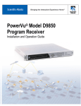
PowerVu Model D9858
Advanced Receiver Transcoder
Installation and Operation Guide
Please Read This Entire Guide
Veuillez lire entièrement ce guide
Bitte das gesamte Handbuch durchlesen
Sírvase leer completamente la presente guía
Si prega di leggere completamente questa guida
Important:
Please read this entire guide before you install or operate this product. Give
particular attention to all safety statements.
Important:
Veuillez lire entièrement ce guide avant d'installer ou d'utiliser ce produit. Prêtez
une attention particulière à toutes les règles de sécurité.
Zu beachten:
Bitte lesen Sie vor Aufstellen oder Inbetriebnahme des Gerätes dieses Handbuch in
seiner Gesamtheit durch. Achten Sie dabei besonders auf die Sicherheitshinweise.
Importante:
Sírvase leer la presente guía antes de instalar o emplear este producto. Preste
especial atención a todos los avisos de seguridad.
Importante:
Prima di installare o usare questo prodotto si prega di leggere completamente
questa guida, facendo particolare attenzione a tutte le dichiarazioni di sicurezza.
®
PowerVu Model D9858
Advanced Receiver Transcoder
Installation and Operation Guide
Notices
Trademark Acknowledgements
• Cisco, Cisco Systems, the Cisco logo, the Cisco Systems logo, Scientific Atlanta
PowerVu and SciCare are registered trademarks or trademarks of Cisco Systems,
Inc. and/or its affiliates in the U.S. and certain other countries.
All other trademarks mentioned in this document are the property of their respective owners.
Publication Disclaimer
Cisco Systems, Inc. assumes no responsibility for errors or omissions that may
appear in this publication. We reserve the right to change this publication at any
time without notice. This document is not to be construed as conferring by
implication, estoppel, or otherwise any license or right under any copyright or
patent, whether or not the use of any information in this document employs an
invention claimed in any existing or later issued patent.
Copyright
© 2008 Cisco Systems, Inc. All rights reserved. Printed in United States of America.
Information in this publication is subject to change without notice. No part of this
publication may be reproduced or transmitted in any form, by photocopy,
microfilm, xerography, or any other means, or incorporated into any information
retrieval system, electronic or mechanical, for any purpose, without the express
permission of Scientific-Atlanta, Inc.
AVC/MPEG-4/H.264 Products
With respect to each AVC/MPEG-4/H.264 product, Scientific Atlanta is obligated
to provide the following notice:
THIS PRODUCT IS LICENSED UNDER THE AVC PATENT PORTFOLIO
LICENSE FOR THE PERSONAL AND NON-COMMERCIAL USE OF A
CONSUMER TO (i) ENCODE VIDEO IN COMPLIANCE WITH THE AVC
STANDARD ("AVC VIDEO") AND/OR (ii) DECODE AVC VIDEO THAT WAS
ENCODED BY A CONSUMER ENGAGED IN A PERSONAL AND NONCOMMERCIAL ACTIVITY AND/OR WAS OBTAINED FROM A VIDEO
PROVIDER LICENSED TO PROVIDE AVC VIDEO. NO LICENSE IS GRANTED
OR SHALL BE IMPLIED FOR ANY OTHER USE. ADDITIONAL INFORMATION
MAY BE OBTAINED FROM MPEG LA, L.L.C. SEE HTTP://
WWW.MPEGLA.COM.
Accordingly, please be advised that service providers, content providers and
broadcasters are required to obtain a separate use license from MPEG LA prior to
any use of AVC/MPEG-4/H.264 encoders and/or decoders.
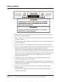
Safety Precautions
This symbol alerts you to
the presence of uninsulated
dangerous voltage inside
the product enclosure that
poses a risk of electric shock.
CAUTION
RISK OF ELECTRIC SHOCK
DO NOT OPEN
This symbol alerts you to
important operating and
maintenance (servicing)
instructions included
with this product.
CAUTION
TO REDUCE THE RISK OF ELECTRICAL SHOCK, DO NOT REMOVE
COVERS FROM THIS UNIT. NO USER-SERVICEABLE PARTS INSIDE.
REFER SERVICING TO QUALIFIED PERSONNEL. SEE ADDITIONAL
SAFETY INSTRUCTIONS BELOW.
WARNING
TO REDUCE THE RISK OF ELECTRICAL SHOCK, DO NOT EXPOSE
THIS PRODUCT TO RAIN OR MOISTURE.
1. Read Instructions – All the safety and operating instructions should be read
before the product is operated.
2. Retain Instructions – The safety and operating instructions should be retained
for future reference.
3. Heed Warnings – All warnings on the product and in the operating instructions
should be adhered to.
4. Follow Instructions – All operating and use instructions should be followed.
5. Cleaning – Unplug this product from the wall outlet before cleaning. Do not use
liquid cleaners or aerosol cleaners. Use a damp cloth for cleaning.
Exception: A product that is meant for uninterrupted service and that, for some
specific reason, such as the possibility of the loss of an authorization code for a
CATV converter, is not intended to be unplugged by the user for cleaning or any
other purpose, may exclude the reference to unplugging the product in the
cleaning description above.
6. Attachments – Do not use attachments not recommended by the product
manufacturer as they may cause hazards.
7. Water and Moisture – Do not use this product near water – for example, near a
bath tub, wash bowl, kitchen sink, or laundry tub; in a wet basement; or near a
swimming pool; and the like.
8. Accessories – Do not place this product on an unstable cart, stand, tripod,
bracket, or table.
The product may fall, causing serious injury to a child or adult, and serious
damage to the product.
4023074 Rev B
Model D9858 Advanced Receiver Transcoder Installation and Operation Guide
iii
Safety Precautions, Continued
Use only with a cart, stand, tripod, bracket, or table recommended by the
manufacturer, or sold with the product. Any mounting of the product should
follow the manufacturer’s instructions, and should use a mounting accessory
recommended by the manufacturer.
9. A product and cart combination should be moved with care. Quick stops,
excessive force, and uneven surfaces may cause the product and cart
combination to overturn.
PORTABLE CART WARNING
10. Ventilation – Slots and openings in the cabinet are provided for ventilation and
to ensure reliable operation of the product and to protect it from overheating,
and these openings must not be blocked or covered. The openings should never
be blocked by placing the product on a bed, sofa, rug, or other similar surface.
This product should not be placed in a built-in installation such as a bookcase or
rack unless proper ventilation is provided or the manufacturer’s instructions
have been adhered to.
11. Power Sources – This product should be operated only from the type of power
source indicated on the marking label. If you are not sure of the type of power
supply to your home, consult your product dealer or local power company. For
products intended to operate from battery power, or other sources, refer to the
operating instructions.
12. Grounding or Polarization – This product may be equipped with a polarized
alternating-current line plug (a plug having one blade wider than the other).
This plug will fit into the power outlet only one way. This is a safety feature. If
you are unable to insert the plug fully into the outlet, try reversing the plug. If
the plug should still fail to fit, contact your electrician to replace your obsolete
outlet. Do not defeat the safety purpose of the polarized plug.
Alternate Warnings – This product is equipped with a three-wire groundingtype plug, a plug having a third (grounding) pin. This plug will only fit into a
grounding-type power outlet. This is a safety feature. If you are unable to insert
the plug into the outlet, contact your electrician to replace your obsolete outlet.
Do not defeat the safety purpose of the grounding-type plug.
iv
Model D9858 Advanced Receiver Transcoder Installation and Operation Guide
4023074 Rev B
Safety Precautions, Continued
13. Power-Cord Protection – Power-supply cords should be routed so that they are
not likely to be walked on or pinched by items placed upon or against them,
paying particular attention to cords at plugs, convenience receptacles, and the
point where they exit from the product.
14. Protective Attachment Plug – The product is equipped with an attachment plug
having overload protection. This is a safety feature. See Instruction Manual for
replacement or resetting of protective device. If replacement of the plug is
required, be sure the service technician has used a replacement plug specified
by the manufacturer that has the same overload protection as the original plug.
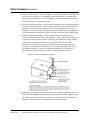
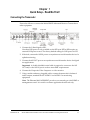
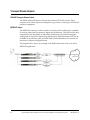
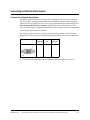
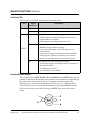
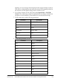
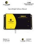
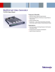
15. Outdoor Antenna Grounding – If an outside antenna or cable system is
connected to the product, be sure the antenna or cable system is grounded so as
to provide some protection against voltage surges and built-up static charges.
Article 810 of the National Electrical Code, ANSI/NFPA 70, provides
information with regard to proper grounding of the mast and supporting
structure, grounding of the lead-in wire to an antenna discharge unit, size of
grounding conductors, location of antenna-discharge unit, connection to
grounding electrodes, and requirements for the grounding electrode.
Figure 1. Outdoor antenna grounding
16. Lightning – For added protection for this product during a lightning storm, or
when it is left unattended and unused for long periods of time, unplug it from
the wall outlet and disconnect the antenna or cable system. This will prevent
damage to the product due to lightning and power-line surges.
4023074 Rev B
Model D9858 Advanced Receiver Transcoder Installation and Operation Guide
v
Safety Precautions, Continued
17. Power Lines – An outside antenna system should not be located in the vicinity
of overhead power lines or other electric light or power circuits, or where it can
fall into such power lines or circuits. When installing an outside antenna system,
extreme care should be taken to keep from touching such power lines or circuits
as contact with them might be fatal.
18. Overloading – Do not overload wall outlets, extension cords, or integral
convenience receptacles as this can result in a risk of fire or electric shock.
19. Object and Liquid Entry – Never push objects of any kind into this product
through openings as they may touch dangerous voltage points or short-out
parts that could result in a fire or electric shock. Never spill liquid of any kind on
the product.
20. Servicing – Do not attempt to service this product yourself as opening or
removing covers may expose you to dangerous voltage or other hazards. Refer
all servicing to qualified service personnel.
21. Damage Requiring Service – Unplug this product from the wall outlet and refer
servicing to qualified service personnel under the following conditions:
a) When the power-supply cord or plug is damaged,
b) If liquid has been spilled, or objects have fallen into the product,
c) If the product has been exposed to rain or water,
d) If the product does not operate normally by following the operating
instructions. Adjust only those controls that are covered by the operating
instructions as an improper adjustment of other controls may result in damage
and will often require extensive work by a qualified technician to restore the
product to its normal operation,
e) If the product has been dropped or damaged in any way, and
f) When the product exhibits a distinct change in performance – this indicates a
need for service.
22. Replacement Parts – When replacement parts are required, be sure the service
technician has used replacement parts specified by the manufacturer or have the
same characteristics as the original part. Unauthorized substitutions may result
in fire, electric shock, or other hazards.
23. Safety Check – Upon completion of any service or repairs to this product, ask
the service technician to perform safety checks to determine that the product is
in proper operating condition.
24. Wall or Ceiling Mounting – The product should be mounted to a wall or ceiling
only as recommended by the manufacturer.
25. Heat – The product should be situated away from heat sources such as
radiators, heat registers, stoves, or other products (including amplifiers) that
produce heat.
vi
Model D9858 Advanced Receiver Transcoder Installation and Operation Guide
4023074 Rev B
Safety Precautions, Continued
Protect yourself from electric shock and your system from damage!
• This product complies with international safety and design standards. Observe all safety
procedures that appear throughout this guide, and the safety symbols that are affixed to
this product.
• If circumstances impair the safe operation of this product, stop operation and secure this
product against further operation.
Avoid personal injury and product damage! Do not proceed beyond any symbol until
you fully understand the indicated conditions!
You will find this symbol on the product and/or in the literature that
accompanies this product.
It indicates important operating or maintenance instructions.
You may find this symbol on the product and/or in the literature that
accompanies this product.
It indicates a live terminal; the symbol pointing to the terminal device.
You may find this symbol on the product and/or in the literature that
accompanies this product.
It indicates a protective earth terminal.
You may find this symbol on the product and/or in the literature that
accompanies this product.
It indicates excessive or dangerous heat.
Power
• Important! This is a Class I product. You must earth this product.
• This product plugs into a socket-outlet. The socket-outlet must be near this product,
and must be easily accessible. Connect this product only to the power source that is
indicated on the back panel of this product. If this product does not have a mains
power switch, the power cord serves this purpose.
Enclosure
• Do not allow moisture to enter this product.
• Do not open the enclosure of this product unless otherwise specified.
• Do not push objects through openings in the enclosure of this product.
Cables
• Always disconnect all power cables before servicing this product.
• Always pull on the plug or the connector to disconnect a cable. Never pull on the cable
itself.
• Do not walk on or place stress on cables or plugs.
Factory service
• Refer service only to service personnel who are authorized by the factory.
4023074 Rev B
Model D9858 Advanced Receiver Transcoder Installation and Operation Guide
vii
Règles de sécurité
Protégez-vous des risques d'électrocution et protégez votre système contre les
endommagements éventuels.
• Ce produit respecte les standards internationaux de sécurité et de conception. Veuillez
observer toutes les procédures de sécurité qui apparaissent dans ce guide, ainsi que les
symboles de sécurité qui figurent sur le produit.
• Si, du fait des circonstances, ce produit cesse de fonctionner normalement, cessez de
l'utiliser et empêchez-en l'utilisation future.
Évitez le risque de blessures et de dommages aux produits! Ne procédez à aucune tâche
tant que vous n'aurez pas entièrement assimilé les conditions indiquées par un symbole!
Ce symbole figure dans la documentation accompagnant ce produit. Il indique
d'importantes instructions de fonctionnement ou d'entretien.
Ce symbole peut être attaché à ce produit. Il indique une borne sous tension; la
direction indique la borne.
Ce symbole peut être attaché à ce produit. Il indique une borne de terre de
protection.
Ce symbole peut être attaché à ce produit. Il indique une température excessive ou
dangereuse.
Alimentation
• Important! Ce produit fait partie de la classe I. Vous devez le mettre à la terre.
• Ce produit se branche dans une prise murale. Cette dernière doit être placée à
proximité du produit et doit être facilement accessible.
• Ne branchez ce produit qu'à la source d'alimentation indiquée sur son panneau arrière.
• Si ce produit n'a pas d'interrupteur d'alimentation générale, le cordon d'alimentation
remplit ce rôle.
Enceinte
• Ne laissez pas l'humidité pénétrer dans ce produit.
• N'ouvrez pas l'enceinte de ce produit, sauf instructions contraires.
• Ne forcez pas d'objets dans les ouvertures du boîtier.
Câbles
• Débranchez toujours tous les cordons d'alimentation avant de réparer ce produit.
• Tirez toujours sur la prise ou le connecteur pour débrancher un câble. Ne tirez jamais
directement sur le câble.
• Ne marchez pas sur les câbles ou les prises et n'y exercez aucune pression.
Réparations effectuées à l'usine
• Ne confiez les travaux de réparations qu'au personnel autorisé par l'usine.
viii
Model D9858 Advanced Receiver Transcoder Installation and Operation Guide
4023074 Rev B
Sicherheitsvorkehrungen
Schützen Sie sich gegen elektrischen Schlag, und Ihr Gerät gegen Beschädigung!
• Dieses Gerät entspricht internationalen Sicherheits-und Ausführungsnormen. Beachten
Sie alle in diesem Handbuch enthaltenen Sicherheitshinweise sowie die am Gerät
angebrachten Warnzeichen.
• Sollten örtliche Umstände den sicheren Betrieb dieses Gerätes beeinträchtigen, schalten
Sie es ab und sichern es gegen weitere Benutzung.
Vermeiden Sie Verletzungen sowie Beschädigung des Gerätes! Wenn Sie zu einem der
folgenden Warnzeichen gelangen, nicht weiterarbeiten, bis Sie seine Bedeutung voll
verstanden haben!
Dieses Symbol erscheint auf dem Gerät und/oder in der ihm beiliegenden
Literatur. Es bedeutet wichtige, zu beachtende Betriebs-oder
Wartungsanweisungen.
Wenn dieses Zeichen am Gerät angebracht ist, warnt es vor einer
spannungsführenden Stelle.
Dieses Symbol kennzeichnet auf dem Gerät die Anschlußstelle der Sicherheitserde.
Wenn dieses Zeichen am Gerät angebracht ist, warnt es vor heißen Stellen, die zu
Verbrennungen führen können.
Netzspannung
• Wichtig! Dieses Gerät ist ein Produkt der Schutzklasse I. Es muß geerdet werden.
• Das Gerät ist an einer Steckdose anzuschließen. Diese muß sich leicht zugänglich in
unmittelbarer Nähe des Gerätes befinden.
• Die Netzversorgung muß den auf der Rückwand des Gerätes angegebenen Werten
entsprechen.
• Falls sich kein Hauptschalter am Gerät befindet, dient das Netzkabel diesem Zweck.
Gehäuse
• Das Innere des Gerätes ist vor Feuchtigkeit zu schützen.
• Das Gehäuse ist nicht zu öffnen.
• Niemals einen Gegenstand durch die Gehäuseöffnungen einführen!
Kabel
• Vor jeglicher Wartung des Gerätes sind alle Kabel zu entfernen.
• Hierzu grundsätzlich am Stecker oder Verbindungsstück und niemals am Kabel selber
ziehen.
• Nicht auf die Kabel oder Stecker treten oder diese einer Zugbelastung aussetzen.
Hersteller-Wartung
Wartungsarbeiten sind nur durch vom Hersteller autorisierte Techniker vorzunehmen.
4023074 Rev B
Model D9858 Advanced Receiver Transcoder Installation and Operation Guide
ix
Precauciones de seguridad
¡Protéjase contra la electrocución y proteja su sistema contra los daños!
• Este producto cumple con los criterios internacionales de seguridad y diseño. Observe
todas los procedimientos de seguridad que aparecen en esta guía, y los símbolos de
seguridad adheridos a este producto.
• Si las circunstancias impiden la operación segura de este producto, suspenda la operación
y asegure este producto para que no siga funcionando.
¡Evite lastimarse y evite dañar el producto! No avance más allá de cualquier símbolo
hasta comprender completamente las condiciones indicadas!
Encontrará este símbolo en el impreso que acompaña a este producto. Este símbolo
indica instrucciones importantes de funcionamiento o mantenimiento.
Es posible que este símbolo esté pegado al producto. Este símbolo indica un
terminal vivo, la flecha apunta hacia el aparato terminal
Podría encontrar este símbolo pegado al producto. Este símbolo indica un terminal
de protección de tierra.
Podría encontrar este símbolo pegado al producto. Este símbolo indica calor
excesivo o peligroso.
Power
• Importante! Este es un producto de Clase I. Tiene que estar conectado a tierra.
• Este producto se conecta a un enchufe. El enchufe necesita estar cerca del producto y
ser fácilmente accesible.
• Conecte este producto únicamente a la fuente de suministro eléctrico indicada en el
panel posterior del producto.
• Si el producto no tiene interruptor para la linea principal, utilice el cordón toma de
corriente para este propósito.
Cubierta
• No permita que la humedad penetre en este producto.
• No abra la cubierta del producto a menos que se indique lo contrario.
• No introduzca objetos a través de las aberturas de la cubierta del producto.
Cables
• Siempre desconectar todos los cables eléctricos antes de revisar o reparar el producto.
• Tire siempre del enchufe o del conector para desconectar un cable. Nunca tire del cable
mismo.
• No camine ni aplique presión sobre los cables o enchufes..
Revisión y reparación de fábrica
Solo personal aprobado por la fábrica puede darle servicio al producto.
x
Model D9858 Advanced Receiver Transcoder Installation and Operation Guide
4023074 Rev B
Precauzioni di sicurezza
Proteggetevi da scosse elettriche e proteggete il vostro sistema da possibili danni!
• Questo prodotto soddisfa le norme internazionali per la sicurezza ed il design. Seguite
tutte le procedure di sicurezza contenute in questa guida e i simboli di sicurezza applicati
al prodotto.
• Se circostanze avverse compromettono la sicurezza d'uso di questo prodotto,
interrompetene l'uso e assicuratevi che il prodotto non venga più utilizzato.
Evitare infortuni alla persona e danni al prodotto! Non procedere oltre a qualunque
simbolo fino a quando non si siano comprese pienamente le condizioni indicate!
Questo simbolo, che appare nella letteratura di accompagnamento del prodotto,
indica importanti istruzioni d'uso e di manutenzione.
Sul prodotto potete vedere questo simbolo che indica un dispositivo terminale
sotto tensione; la freccia punta verso il dispositivo.
Potrete trovare il presente simbolo applicato a questo prodotto. Questo simbolo
indica un terminale protettivo di messa a terra.
Potrete trovare il presente simbolo attaccato a questo prodotto. Questo simbolo
indica un calore eccessivo o pericoloso.
Alimentazione
• Importante! Questo prodotto è di Classe I. Va messo a terra.
• Questo prodotto si inserisce in una presa di corrente. La presa di corrente deve essere
in prossimità del prodotto, e deve essere facilmente accessibile.
• Collegare questo prodotto solamente alla fonte di alimentazione indicata sul pannello
posteriore di questo prodotto.
• Se questo prodotto non è dotato di un interruttore principale, il cavo di alimentazione
funge a questo scopo.
Chiusura
• Proteggete da umidità questo prodotto.
• Non aprire la chiusura di questo prodotto a meno che non sia specificato diversamente.
• Non inserire oggetti attraverso le fessure della chiusura.
Cavi
• Staccare sempre tutti i cavi di alimentazione prima di svolgere l'assistenza tecnica al
prodotto.
• Per scollegare un cavo tirate la spina o il connettore, non tirare mai il cavo stesso.
• Non calpestare o sottoporre a sollecitazioni i cavi o le prese.
Riparazionoi di fabbrica
• Per le riparazioni contattate solamente personale tecnico autoizzato dalla fabbrica.
4023074 Rev B
Model D9858 Advanced Receiver Transcoder Installation and Operation Guide
xi
Important Safety Instructions
Read and Retain Instructions
Carefully read all safety and operating instructions before operating this equipment, and
retain them for future reference.
Follow Instructions and Heed Warnings
Follow all operating and use instructions. Pay attention to all warnings and cautions in the
operating instructions, as well as those that are affixed to this equipment.
Terminology
The terms defined below are used in this document. The definitions given are based on
those found in safety standards.
Service Personnel - The term service personnel applies to trained and qualified individuals
who are allowed to install, replace, or service electrical equipment. The service personnel
are expected to use their experience and technical skills to avoid possible injury to
themselves and others due to hazards that exist in service and restricted access areas.
User and Operator - The terms user and operator apply to persons other than service
personnel.
Ground(ing) and Earth(ing) - The terms ground(ing) and earth(ing) are synonymous. This
document uses ground(ing) for clarity, but it can be interpreted as having the same meaning
as earth(ing).
Electric Shock Hazard
This equipment meets applicable safety standards.
WARNING:
To reduce risk of electric shock, perform only the instructions that are included in the
operating instructions. Refer all servicing to qualified service personnel only.
Electric shock can cause personal injury or even death. Avoid direct contact with dangerous
voltages at all times. The protective ground connection is essential to safe operation and
must be verified before connecting the power supply.
Know the following safety warnings and guidelines:
• Dangerous Voltages
- Only qualified service personnel are allowed to perform equipment installation or
replacement.
- Only qualified service personnel are allowed to remove chassis covers and access any
of the components inside the chassis.
• Grounding
- Do not violate the protective grounding by using an extension cable, power cable, or
autotransformer without a protective ground conductor.
- Take care to maintain the protective grounding of this equipment during service or
repair and to re-establish the protective grounding before putting this equipment back
into operation.
xii
Model D9858 Advanced Receiver Transcoder Installation and Operation Guide
4023074 Rev B
Important Safety Instructions, Continued
Installation Site
When selecting the installation site, comply with the following:
• Protective Ground - The protective ground lead of the building's electrical installation
should comply with national and local requirements.
• Environmental Condition - The installation site should be dry, clean, and ventilated. Do
not use this equipment where it could be at risk of contact with water. Ensure that this
equipment is operated in an environment that meets the requirements as stated in this
equipment's technical specifications, which may be found on this equipment's data sheet.
Installation Requirements
WARNING:
Allow only qualified service personnel to install this equipment.
The installation must conform to all local codes and regulations.
Equipment Placement
WARNING:
Avoid personal injury and damage to this equipment. An unstable mounting surface
may cause this equipment to fall.
To protect against equipment damage or injury to personnel, comply with the following:
• Install this equipment in a restricted access location.
• Do not install near any heat sources such as radiators, heat registers, stoves, or other
equipment (including amplifiers) that produce heat.
• Place this equipment close enough to a mains AC outlet to accommodate the length of
this equipment's power cord.
• Route all power cords so that people cannot walk on, place objects on, or lean objects
against them. This may pinch or damage the power cords. Pay particular attention to
power cords at plugs, outlets, and the points where the power cords exit this equipment.
• Use only with a cart, stand, tripod, bracket, or table specified by the manufacturer, or sold
with this equipment.
• Make sure the mounting surface or rack is stable and can support the size and weight of
this equipment.
• The mounting surface or rack should be appropriately anchored according to
manufacturer's specifications. Ensure this equipment is securely fastened to the mounting
surface or rack where necessary to protect against damage due to any disturbance and
subsequent fall.
Ventilation
This equipment has openings for ventilation to protect it from overheating. To ensure
equipment reliability and safe operation, do not block or cover any of the ventilation
openings. Install the equipment in accordance with the manufacturer's instructions.
4023074 Rev B
Model D9858 Advanced Receiver Transcoder Installation and Operation Guide
xiii
Important Safety Instructions, Continued
Rack Mounting Safety Precautions
Mechanical Loading
Make sure that the rack is placed on a stable surface. If the rack has stabilizing devices,
install these stabilizing devices before mounting any equipment in the rack.
WARNING:
Avoid personal injury and damage to this equipment. Mounting this equipment in the
rack should be such that a hazardous condition is not caused due to uneven mechanical
loading.
Reduced Airflow
When mounting this equipment in the rack, do not obstruct the cooling airflow through the
rack. Be sure to mount the blanking plates to cover unused rack space. Additional
components such as combiners and net strips should be mounted at the back of the rack, so
that the free airflow is not restricted.
CAUTION:
Installation of this equipment in a rack should be such that the amount of airflow
required for safe operation of this equipment is not compromised.
Elevated Operating Ambient Temperature
Only install this equipment in a humidity- and temperature-controlled environment that
meets the requirements given in this equipment's technical specifications.
CAUTION:
If installed in a closed or multi-unit rack assembly, the operating ambient temperature
of the rack environment may be greater than room ambient temperature. Therefore,
install this equipment in an environment compatible with the manufacturer's
maximum rated ambient temperature.
Handling Precautions
When moving a cart that contains this equipment, check for any of the following possible
hazards:
WARNING:
Avoid personal injury and damage to this equipment! Move any
equipment and cart combination with care. Quick stops, excessive force,
and uneven surfaces may cause this equipment and cart to overturn.
• Use caution when moving this equipment/cart combination to avoid injury from tipover.
• If the cart does not move easily, this condition may indicate obstructions or cables that
may need to be disconnected before moving this equipment to another location.
• Avoid quick stops and starts when moving the cart.
• Check for uneven floor surfaces such as cracks or cables and cords.
xiv
Model D9858 Advanced Receiver Transcoder Installation and Operation Guide
4023074 Rev B
Important Safety Instructions, Continued
Grounding
This section provides instructions for verifying that the equipment is properly grounded.
Safety Plugs (USA Only)
Equipment protection Class I - Scientific Atlanta supplies a mains cord with a 3-terminal
(grounding-type) safety plug. Do not defeat the safety purpose of the grounding-type or
polarized safety plug.
To properly ground this equipment, follow these safety guidelines:
• Grounding-Type Plug - For a 3-terminal plug (one terminal on this plug is a protective
grounding pin), insert the plug into a grounded mains, 3-terminal outlet.
Note: This plug fits only one way. If this plug cannot be fully inserted into the outlet,
contact an electrician to replace the obsolete 3-terminal outlet.
Safety Plugs (European Union)
• Class I Mains Powered Equipment - Provided with a 3-terminal AC inlet and requires
connection to a 3-terminal mains supply outlet via a 3-terminal power cord for proper
connection to the protective ground.
Note: The equipotential bonding terminal provided on some equipment is not designed
to function as a protective ground connection.
Equipotential Bonding
If this equipment is equipped with an external chassis terminal marked with the IEC 604175020 chassis icon (
), or 5017 (
), the installer should refer to CENELEC standard EN
50083-1 or IEC standard IEC 60728-11 for correct equipotential bonding connection
instructions.
4023074 Rev B
Model D9858 Advanced Receiver Transcoder Installation and Operation Guide
xv
Important Safety Instructions, Continued
AC Power
Important: This equipment is Class I equipment, it must be grounded.
• If this equipment plugs into an outlet, the outlet must be near this equipment, and must
be easily accessible.
• Connect this equipment only to the power sources that are identified on the equipmentrating label normally located close to the power inlet connector(s).
• If this equipment has two power sources be sure to disconnect all power sources before
working on this equipment.
• If this equipment does not have a main power switch, the power cord connector serves as
the disconnect device.
• Always pull on the plug or the connector to disconnect a cable. Never pull on the cable
itself.
• Unplug this equipment when unused for long periods of time.
Circuit Overload
Know the effects of circuit overloading before connecting this equipment to the power
supply.
CAUTION:
Consider the connection of this equipment to the supply circuit and the effect that
overloading of circuits might have on overcurrent protection and supply wiring. Refer
to the information on the equipment-rating label when addressing this concern.
General Servicing Precautions
WARNING:
Avoid electric shock! Opening or removing this equipment's cover may expose you to
dangerous voltages.
Be aware of the following general precautions and guidelines:
• Servicing - Refer all servicing to qualified service personnel. Servicing is required when
this equipment has been damaged in any way, such as power supply cord or plug is
damaged, liquid has been spilled or objects have fallen into this equipment, this
equipment has been exposed to rain or moisture, does not operate normally, or has been
dropped.
• Wristwatch and Jewelry - For personal safety and to avoid damage of this equipment
during service and repair, do not wear electrically conducting objects such as a
wristwatch or jewelry.
• Lightning - Do not work on this equipment, or connect or disconnect cables, during
periods of lightning.
• Labels - Do not remove any warning labels. Replace damaged or illegible warning labels
with new ones.
• Covers - Do not open the cover of this equipment and attempt service unless instructed to
do so in the instructions. Refer all servicing to qualified service personnel only.
• Moisture - Do not allow moisture to enter this equipment.
• Cleaning - Use a damp cloth for cleaning.
xvi
Model D9858 Advanced Receiver Transcoder Installation and Operation Guide
4023074 Rev B
Important Safety Instructions, Continued
Safety Checks - After service, assemble this equipment and perform safety checks
to ensure it is safe to use before putting it back into operation.
Accessories
Use only attachments or accessories specified by the manufacturer.
4023074 Rev B
xvii
xviii
4023074 Rev B
Contents
Safety Precautions ......................................................................................................................................iii
Règles de sécurité .................................................................................................................................... viii
Sicherheitsvorkehrungen ...........................................................................................................................ix
Precauciones de seguridad ......................................................................................................................... x
Precauzioni di sicurezza .............................................................................................................................xi
Important Safety Instructions....................................................................................................................xii
About This Manual ................................................................................................................................. xxiii
Chapter 1
Quick Setup - Read Me First!
Connecting the Transcoder..............................................................................................1-1
Front Panel Setup ..............................................................................................................1-3
Setting Up TS Input and Tuning.....................................................................................1-4
Assigning a Program Channel to a Program Entry .....................................................1-5
Input/Output Settings .....................................................................................................1-6
Chapter 2
Introduction
D9858 Advanced Receiver Transcoder ..........................................................................2-2
Transport Stream Outputs ...............................................................................................2-4
Control and Management Interfaces..............................................................................2-5
Chapter 3
Installation
Section A - Rack Installation .................................................................................................3-2
General................................................................................................................................3-2
Installing the D9858 Advanced Receiver Transcoder..................................................3-3
Section B - Rear Connector Panel .........................................................................................3-5
Overview ............................................................................................................................3-5
Section C - Connecting the Input/Output Signals ..................................................................3-7
Connecting the RF Inputs ................................................................................................3-7
Connecting the ASI Input ................................................................................................3-7
Section D - Connecting the Input/Output Signals ..................................................................3-8
Connecting the Video Outputs .......................................................................................3-8
Connecting the Audio Outputs.......................................................................................3-9
Connecting the Ethernet Management Interface........................................................3-10
Connecting the IP TS Output ........................................................................................3-11
4023074 Rev B
Model D9858 Advanced Receiver Transcoder Installation and Operation Guide
xix
Contents, Continued
Connecting the ASI Outputs .........................................................................................3-12
Connecting an External Alarm System........................................................................3-13
Connecting the RS-232 Data Interface .........................................................................3-14
Chapter 4
Front Panel Operation
About the Front Panel ......................................................................................................4-2
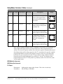
Keypad Convention..........................................................................................................4-4
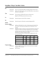
Startup Screen....................................................................................................................4-6
Main Menu.......................................................................................................................4-10
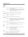
Status Menu .....................................................................................................................4-11
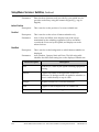
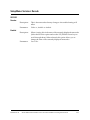
Status Menu: General .....................................................................................................4-12
Status Menu: Services.....................................................................................................4-14
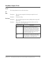
Status Menu: TS Input ....................................................................................................4-16
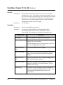
Status Menu: TS Output.................................................................................................4-20
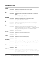
Setup Menu ......................................................................................................................4-21
Setup Menu: Admin .......................................................................................................4-22
Setup Menu: TS Input.....................................................................................................4-27
Setup Menu: TS Input: Input: ASI ................................................................................4-28
Setup Menu: TS Input: Input: RF1-RF4........................................................................4-29
Setup Menu: TS Input: Tune Mode: Custom ..............................................................4-32
Setup Menu: TS Input: Tune Mode: Custom ..............................................................4-33
Setup Menu: IP ................................................................................................................4-34
Setup Menu: Services......................................................................................................4-37
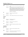
Setup Menu: Services: Video .........................................................................................4-38
Setup Menu: Services: Audio ........................................................................................4-42
Setup Menu: Services: Captions....................................................................................4-43
Setup Menu: Services: Subtitles ...................................................................................4-44
Setup Menu: Services: Decode ......................................................................................4-47
Setup Menu: Outputs .....................................................................................................4-48
Setup Menu: Outputs: TS Out.......................................................................................4-49
Setup Menu: Outputs: TS Out: ASI, Continued .........................................................4-51
Setup Menu: Outputs: TS Out: DPM............................................................................4-57
Setup Menu: Outputs: TS Out: Transcode ..................................................................4-68
Setup Menu: CA ..............................................................................................................4-72
Setup Menu: Alarm/Warning.......................................................................................4-75
Setup Menu: Noise Cutoff .............................................................................................4-77
About Menu.....................................................................................................................4-81
Versions Menu.................................................................................................................4-83
Diagnostics Menu ...........................................................................................................4-85
xx
Model D9858 Advanced Receiver Transcoder Installation and Operation Guide
4023074 Rev B
Contents, Continued
Diagnostics Menu: PSI....................................................................................................4-86
Diagnostics Menu: PSI, PowerOn, Health Monitor ...................................................4-87
Chapter 5
Service and Maintenance
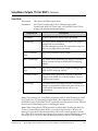
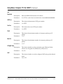
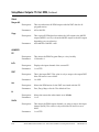
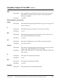
Section A - Front Panel LEDs ................................................................................................5-2
Introduction .......................................................................................................................5-2
Messages.............................................................................................................................5-4
Section B - Power Supply Replacement ..............................................................................5-19
Introduction .....................................................................................................................5-19
Chapter 6
Customer Information
Product Support ................................................................................................................6-2
Returning Products...........................................................................................................6-4
Appendix A Technical Specifications
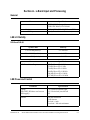
Section A - L-Band Input and Processing .............................................................................A-3
General...............................................................................................................................A-3
LNB LO Stability ..............................................................................................................A-3
LNB Power and Control..................................................................................................A-3
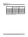
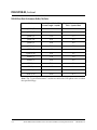
DVB-S/DVB-S2 ................................................................................................................A-4
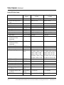
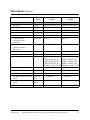
Section B - Video Inputs/Outputs and Processing ................................................................A-7
General...............................................................................................................................A-7
Video Inputs .....................................................................................................................A-7
Video Outputs ..................................................................................................................A-7
Audio Inputs/Outputs..................................................................................................A-10
VBI Data Input/Output ................................................................................................A-10
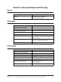
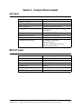
Section C - Transport Stream Outputs................................................................................A-11
ASI Output .....................................................................................................................A-11
MPEGoIP Output ...........................................................................................................A-11
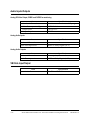
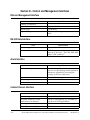
Section D - Control and Management Interfaces.................................................................A-12
Ethernet Management Interface...................................................................................A-12
RS-232 Data Interface.....................................................................................................A-12
Alarm Interface...............................................................................................................A-12
Contact Closure Interface..............................................................................................A-12
Section E - Power and General Specifications....................................................................A-13
General.............................................................................................................................A-13
Power ...............................................................................................................................A-13
4023074 Rev B
Model D9858 Advanced Receiver Transcoder Installation and Operation Guide
xxi
Contents, Continued
Section F - Mechanical/Environmental ...............................................................................A-14
Mechanical ......................................................................................................................A-14
Environment ...................................................................................................................A-14
Appendix B Default Settings
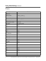
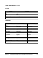
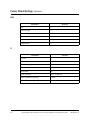
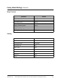
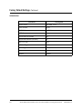
Factory Default Settings .................................................................................................. B-2
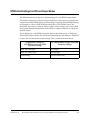
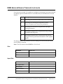
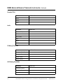
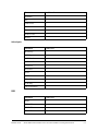
DPM Default Settings for Different Output Modes .................................................... B-9
Appendix C Lock Levels
D9858 Advanced Receiver Transcoder Lock Levels ...................................................C-2
Appendix D Equipment and Accessories
Accessory Kits for the D9858 Advanced Receiver Transcoder .................................D-2
Appendix E Compliance
Applicable Standards and Notices ................................................................................ E-1
xxii
Model D9858 Advanced Receiver Transcoder Installation and Operation Guide
4023074 Rev B
About This Manual
Objective
This manual describes how to install, use and maintain the Model D9858 Advanced
Receiver Transcoder.
Note: The manual describes all available options for the D9858 Advanced Receiver
Transcoder. Your D9858 Advanced Receiver Transcoder may only have some of the
features described in this manual.
Audience
The audience of this manual includes users (operators) and service personnel who
are responsible for the installation, configuration, operation, monitoring and service
of the D9858 Advanced Receiver Transcoder.
Required Knowledge
To use this documentation, the user should have a basic knowledge of the
technology used in relation to this product. Service personnel should have
additional skills and be familiar with cabling, electronic circuitry, and wiring
practices.
This manual is intended for operators who are responsible for the configuration,
remote operation and maintenance of the D9858 Advanced Receiver Transcoder.
4023074 Rev B
Model D9858 Advanced Receiver Transcoder Installation and Operation Guide
xxiii
xxiv
Model D9858 Advanced Receiver Trancoder Installation and Operation Guide
4023074 Rev B
Chapter 1
Quick Setup - Read Me First!
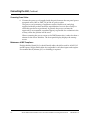
Connecting the Transcoder
Proceed as follows to connect the Model D9858 Advanced Receiver Transcoder to
other equipment.
MOPEG
1. Connect the L-Band signal to RF1.
Note that LNB power is only available on the RF1 port. RF2 to RF4 require an
external LNB power source. The factory default setting for LNB power is OFF.
2. If desired, connect the ASI IN port to an asynchronous serial interface device for
uplink monitoring.
3. Connect the ASI OUT ports to an asynchronous serial interface device for digital
tier applications.
Important! A double-shielded coaxial cable is required to connect to the ASI
OUT and/or the ASI IN port in order to meet EMC requirements.
4. Connect the Composite Video Outputs to a video monitor.
5. Using a multi-conductor, pluggable cable, connect the transcoder’s balanced
audio outputs, terminal blocks AUDIO 1 and AUDIO 2 to monitoring
equipment.
Note: The Ethernet MANAGEMENT port does not currently provide SNMP or
management control. It is used for software application downloads only.
4023074 Rev B
Model D9858 Advanced Receiver Transcoder Installation and Operation Guide
1-1
Connecting the Unit, Continued
Connecting Power Cables
6. Connect the power cord (supplied with the unit) between the rear panel power
receptacle and a 100V to 240V, 50/60 Hz AC power outlet.
The power cord (consisting of appliance coupler, flexible cord, and plug)
supplied with this product meets the requirements for use in the country for
which this product was purchased. In general, the power cord must be
approved by an acceptable, accredited agency responsible for evaluation in the
country where the product will be used.
When connecting the power source to the D9858 transcoder, it takes less than a
minute for the unit to initialize. The front panel display displays the startup
screen.
Maintenance of EMC Compliance
Double-shielded (braid/foil or braid/braid) cables should be used for all ASI I/O
and RF inputs. Single-shield cables are acceptable for all other inputs and outputs.
For terminal block (Alarms) I/O, no shielding is required.
1-2
Model D9858 Advanced Receiver Transcoder Installation and Operation Guide
4023074 Rev B
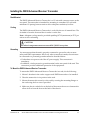
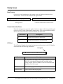
Front Panel Setup
Locking/Unlocking the Front Panel
The front panel can be locked or unlocked using the front panel keypad.
Proceed as follows to unlock the front panel using the front panel keypad:
1. When at the Main Menu, press SELECT and then INFO. This will unlock the
front panel keypad and allow you make changes to all the operating parameters;
however, if the keypad remains untouched for the duration of the set timeout
period (default is 60 seconds), the keypad will change back to the Lock state
unless you change the keypad state on the Admin Menu. Likewise you toggle
the keypad lock state back using SELECT and INFO at any time provided the
KB Lock state on the Admin Menu is Enabled. See Keypad Convention,
page 4-4 for instructions on the use of the front panel keypad buttons
2. To disable Lock completely, navigate to Setup: Admin: KB Lock in the LCD
display and press the SELECT key.
3. Change the KB Lock state from Enabled to Disabled.
4. The front panel will now be unlocked allowing you to change any of the
operating parameters.
To lock the front panel, perform the same procedure, except use the
change the state. You will not be prompted to confirm the operation.
4023074 Rev B
D9858 Advanced Receiver Transcoder Installation and Operation Guide
key to
1-3
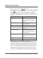
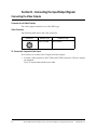
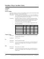
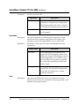
Setting Up TS Input and Tuning
Proceed as follows to set up the TS Input and Tuning:
1. Press the MENU key and use the
arrw keys to navigate to the Setup: TS
Input: Input menu, using the SELECT key to move down each level, and then
use the
arrow keys to set the following parameters. See Keypad
Convention, page 4-4 for instructions on the use of the front panel keypad
buttons, and the Main Menu, page 4-10 for information on the front panel menu
structure.
Entry/Selection
Options
RF1 or ASI
Set to ACT to enable/activate the input.
Note: It is not necessary to set the
tuning parameters if you are using the
ASI input.
LO1, LO2, Xover
LO (Local Oscillator) and Crossover
frequencies in GHz.
Input
4 RF input ports to select.
Modulation
DVB-S or DVB-S2. If set to DVB-S2, set
FEC to Auto.
Freq. Sym Rate and FEC
Type in downlink frequency (in GHz)
If the FEC is unknown, leave it at
"Auto". It must be set to Auto if DVB-S2
modulation is used.
Set LNB Voltage
Only RF1 has DC power.
LNB Voltage options - 13 (V), 18 (V)
and Off.
Rolloff
Only required for DVB-S2.
Net ID
Enter your network ID.
2. Press MENU to exit the menu level and save the changes.
Note: If the changes are saved successfully, the transcoder will return to the
Main Menu. It will search for the signal and display “Acquisition Successful”.
The transcoder will find the first available channel on the network. You can
select another available channel if necessary. If when entering parameters, the
changes cannot be saved successfully, a "Value out of range” or “Invalid
Parameters!" error message appears and you will need to continue editing.
Select 'Yes' to continue editing. If 'No' is selected, all the changes will be lost.
1-4
Model D9858 Advanced Receiver Transcoder Installation and Operation Guide
4023074 Rev B
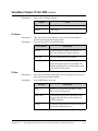
Assigning a Program Channel to a Program Entry
Proceed as follows to assign program channels to program entries:
1. Set up the two Program Entries, PE1 and PE2, for two input program channels
that you are authorized to receive. See Assigning Programs to Program Entries
for more information.
2. Press MENU until you display the startup screen.
PE
Ch #
PE1 1
Channel Name
RF1
Freq:12.658 Lvl:100 Marg:9.9e-9
s
PE1 (the decode Program Entry) is initially displayed.
3. Press the ADV key on the front panel keypad and then the
scroll through the two PEs available.
arrow keys to
4. Press the SELECT key to select a PE (PE1 or PE2) and then the use
arrow
key to move to the right and scroll through the available program channels.
5. Directly enter the channel number for the selected PE using the 0 to 9 keys, and
press SELECT to save the channel selection.
6. Repeat this process to select a program channel for PE2.
4023074 Rev B
D9858 Advanced Receiver Transcoder Installation and Operation Guide
1-5
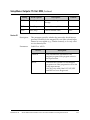
Input/Output Settings
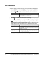
Proceed as follows to configure the Video output format and TS Output settings:
1. Press the MENU key and use the RIGHT arrow key to navigate to the Setup:
Services: Video menu, using the SELECT key to move down each level, and
then use the
arrow keys to navigate and set the video output format.
Entry/Selection
SD Format
Options
Set to Auto (default) or the particular output resolution
for the monitor, e.g., NTSC or PAL.
2. Press MENU to exit the menu level and save the changes.
3. Use the
arrow key to move to the Setup: Outputs: TS Out: ASI or MOIP1
menu, using the SELECT key to move down each level, and then use the
arrow keys to navigate and configure the Output Mode. Refer to DPM
Default Settings for Different Output Modes, page B-9 for information on the
default settings for each output mode, to choose the desired Output Mode.
Entry/Selection
Options
Output Mode
It is recommended to set the Output Mode to
Transcoding. The output mode is factory set to No
Output as the default.
Resync All
Resynchronize the output services, ASI or MOIP1.
Select Yes when prompted.
4. Press MENU to exit the menu level and save the changes.
1-6
Model D9858 Advanced Receiver Transcoder Installation and Operation Guide
4023074 Rev B
Chapter 2
Introduction
Overview
Introduction
This chapter is a general introduction to the Model D9858 Advanced Receiver
Transcoder. It describes the most common applications and interfaces of the
receiver.
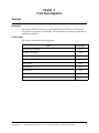
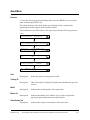
In This Chapter
This chapter contains the following topics.
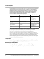
Topic
4023074 Rev B
See Page
D9858 Advanced Receiver Transcoder
2-2
Transport Stream Outputs
2-4
Control and Management Interfaces
2-5
Model D9858 Advanced Receiver Transcoder Installation and Operation Guide
2-1
D9858 Advanced Receiver Transcoder
General Description
The PowerVu® Model D9858 Advanced Receiver Transcoder provides the ability to
deliver MPEG-4 HD services to MPEG-2 CATV head-ends. The Model D9858
receiver will extend the distribution options for MPEG-4 HD from solely MPEG-4
environments to existing MPEG-2 networks. Support for simultaneous dualchannel transcoding will provide the advantage of density for locations requiring
more than just a single channel. A video and two audio monitoring outputs are
available for confidence monitoring of the decrypted incoming MPEG-4 HD
program.
Digital Cable/Telco Program Distribution
The ASI and MPEGoIP transport outputs provide a number of modes including the
capability of carrying up to two decrypted transcoded programs for digital tier
distribution. This helps the compressed video programs to be efficiently distributed
to subscribers equipped with digital set-top boxes. Digital Program Insertion (DPI)
information is also be available along with the video and audio PIDs (Packet
Identifiers) for external ad insertion in compressed digital format. Digital audio
passthrough is supported with sync to the transcoded program output. Compliant
PSI/SI regeneration provides easy integration into a digital tier distribution
network for two transcoded programs.
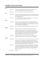
Key Features
The D9858 Advanced Receiver Transcoder provides the following key features:
• Four L-Band inputs
• DVB-S QPSK demodulation
• DVB-S2 QPSK/8PSK demodulation
• PowerVu® conditional access with DES or DVB descrambling
• PowerVu uplink control of transcoding configuration and management
• Decryption and transcoding of up to two programs for digital transport output
• PSI/SI regeneration for both programs
• Dolby® Digital (AC-3) audio decoding for moniroring
• Audio passthrough synchronization for transcoded programs
• Field upgradeable software and security
• Front panel LCD for control & monitoring
• Additional ASI outputs for redundancy
• MPEGoIP output for network connectivity
• Contact closure terminals for simple alarm monitoring
2-2
Model D9858 Advanced Receiver Transcoder Installation and Operation Guide
4023074 Rev B
D9858 Advanced Receiver Transcoder, Continued
Software Update
All software in the D9858 Advanced Receiver Transcoder is stored in non-volatile
memory that can be electrically programmed. New software releases for the D9858
Advanced Receiver Transcoder can be downloaded via the Ethernet 10/100/1000
BaseT Management interface.
4023074 Rev B
Model D9858 Advanced Receiver Transcoder Installation and Operation Guide
2-3
Transport Stream Outputs
DVB-ASI Transport Stream Output
The D9858 Advanced Receiver Transcoder has three DVB-ASI outputs. These
outputs can be used as inputs for multiplexers, groomers or other types of DVB-ASI
reception equipment.
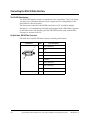
MPEGoIP Output
The MPEGoIP output provides a number of output modes including the capability
of carrying a decrypted program for digital tier distribution. This helps ensure that
compressed video programs are efficiently distributed to households equipped
with digital set-top boxes. Digital Program Insertion (DPI) information will also be
available along with the video and audio PIDs (Packet Identifiers) for external adinsertion in compressed digital format.
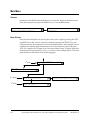
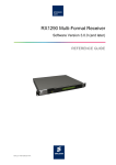
The diagram below shows an example of the D9858 transcoder used in an ASI or
MPEGoIP application.
2-4
Model D9858 Advanced Receiver Transcoder Installation and Operation Guide
4023074 Rev B
Control and Management Interfaces
Ethernet
The Management interface for the D9858 Advanced Receiver Transcoder is the 10/
100/1000 BaseT Ethernet interface. It is used for upgrading the software
application. SNMP or Web GUI control is not supported in this software release.
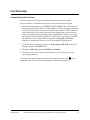
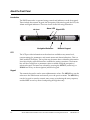
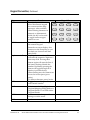
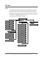
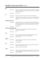
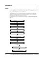
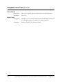
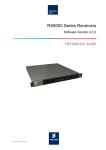
Front Panel Control
The front panel keypad and LCD is used to control the operating parameters of the
D9858 transcoder.
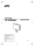
The following diagram shows the front panel with its different sections.
LCD Panel
Alarm LED
Signal LED
Navigation/Selection
4023074 Rev B
Numeric Keypad
Model D9858 Advanced Receiver Transcoder Installation and Operation Guide
2-5
2-6
Model D9858 Advanced Receiver Transcoder Installation and Operation Guide
4023074 Rev B
Chapter 3
Installation
Overview
Introduction
This chapter describes how to install the D9858 Advanced Receiver Transcoder.
Before installing the D9858 transcoder, read all the safety precautions and
guidelines thoroughly.
Qualified Personnel
Only appropriately qualified and trained personnel should attempt to install,
operate or maintain the D9858 Advanced Receiver Transcoder.
WARNING:
Allow only qualified personnel to install this product. Otherwise, personal
injury or equipment damage may occur.
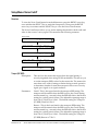
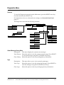
In This Chapter
This chapter contains the following topics.
Topic
4023074 Rev B
See Page
Section A - Rack Installation
3-2
General
3-2
Section B - Rear Connector Panel
3-5
Overview
3-5
Section C - Connecting the Input/Output Signals
3-7
Connecting the RF Inputs
3-7
Section D - Connecting the Input/Output Signals
3-8
Connecting the Video Outputs
3-8
Connecting the Audio Outputs
3-9
Connecting the Ethernet Management Interface
3-10
Connecting the IP TS Output
3-11
Connecting the ASI Outputs
3-12
Connecting an External Alarm System
3-13
Model D9858 Advanced Receiver Transcoder Installation and Operation Guide
3-1
Section A - Rack Installation
General
Power Connection
To operate the transcoder, you must connect it to an AC power source. For
information about connecting the chassis to AC power, see Appendix A - Technical
Specifications.
As Cisco units are designed for continuous operation, some products do not have a
power switch. In this case the mains cord and/or DC power supply cable serve(s) as
the mains disconnect device.
WARNING:
Make sure that at least one end of the power cable(s) remains easily accessible
for unplugging, if you need to switch off the unit. For example: Ensure that the
socket outlet is installed near the product.
WARNING:
To avoid electrical shock, connect the three-prong plug on this product to an
earth-grounded three-pin socket outlet only.
3-2
Model D9858 Advanced Receiver Transcoder Installation and Operation Guide
4023074 Rev B
Installing the D9858 Advanced Receiver Transcoder
Rack Mounted
The D9858 Advanced Receiver Transcoder is a 1U unit with connector access at the
rear panel. The transcoder is intended for mounting in a standard 19" rack with
minimum 1U spacing between units to allow adequate ventilation/air flow.
Cooling
The D9858 Advanced Receiver Transcoder is cooled by the use of internal fans. The
air intake is from the front and the air outlet is on the rear.
Note: Adequate cooling must be provided equalling 107 W (maximum) at 25°C per
unit to avoid overheating.
CAUTION:
The inlet air temperature must not exceed 50°C/122°F at any time.
Grounding
You must ensure that the unit is properly connected to ground in order to meet
safety and EMC requirements. Before any other connection is made, the unit must
be connected to a protected ground terminal as described below:
• Via the three wire power cord of the AC power supply. This connection is
mandatory.
• In addition, via the protective ground terminal on the rear panel of the unit. This
connection provides additional protection of the equipment.
To Mount the D9858 Advanced Receiver Transcoder
To mount the D9858 Advanced Receiver Transcoder in a rack, do the following:
1. Mount L-brackets in the rack to support each D9858 transcoder to be installed.
2. Place the transcoder in its position in the rack.
3. Mount the transcoder securely to the rack by securing the mounting flanges to
the rack using the four screws provided.
4. Make sure the air outlet holes on the back of the transcoder are not obstructed to
allow air flow from the front to the back of the chassis.
4023074 Rev B
Model D9858 Advanced Receiver Transcoder Installation and Operation Guide
3-3
Installing the D9858 Advanced Receiver Transcoder, Continued
To Connect AC Power
To connect AC power to the D9858 Advanced Receiver Transcoder do the
following:
1. Connect the power cord (supplied with the D9858 Advanced Receiver
Transcoder) between the rear panel power receptacle and a 100 to 120/200 to
240 V AC power outlet.
2. Make sure that the power cable is connected to protective ground.
See Grounding, page 3-3 for more information.
The D9858 transcoder is equipped with one power suppy located in the rear of the
chassis. Note the location of the power supply in the event of alarms/warnings
resulting in replacement of a power supply. Alarm messages appear in the Message
Log.
3-4
Model D9858 Advanced Receiver Transcoder Installation and Operation Guide
4023074 Rev B
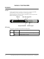
Section B - Rear Connector Panel
Overview
D9858 Advanced Receiver Transcoder Rear Connector Panel
The following diagram shows the rear connector panel of the D9858 transcoder.
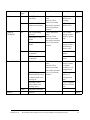
Connectors
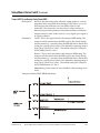
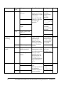
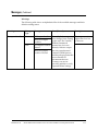
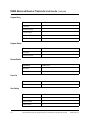
The following table describes the function and type of the various connectors.
Connector
4023074 Rev B
Function
Connector Type
RF Inputs
Each input accepts an LNB signal
input. RF1 provides LNB power for
use when no external LNB power
source is available. RF2 to RF4
require an external LNB power
source.
F
Reference Input
For future use.
BNC
ASI Input
Asynchronous Serial Interface Input. BNC
ASI Outputs
Three Asynchronous Serial Interface BNC
Outputs.
Management
For upgrading the software
application (code downloading) for
the D9858 Advanced Receiver
Transcoder.
Cue Tone/Cue
Trigger Relay
Outputs
Program relay provides
9-pin sub-D female
programmed responses for alarms,
cue trigger states for ad-insertion
equipmnent, or a cue tone output for
connection to ad-insertion
equipment.
RJ45
Model D9858 Advanced Receiver Transcoder Installation and Operation Guide
3-5
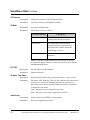
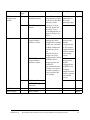
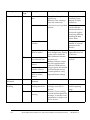
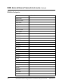
Connector
3-6
Function
Connector Type
RS-232 Data
9-pin sub-D female
RS-232 data output: 7 bits, even
parity, 1 stop bit, up to 38.4 kbps.
These outputs are user-configurable
via the Setup menu on the front
panel.
Composite Video
Outputs
CVBS 1 and CVBS 2 provide two
BNC
identical SD composite video
outputs for monitoring applications.
Balanced Audio
Outputs
Audio 1 and Audio 2 provide two
stereo pairs or four mono channels.
Terminal Blocks
Gnd
Screw
Grounding point for
the transcoder.
Power
AC power
IEC 60320 Sheet 14
Model D9858 Advanced Receiver Transcoder Installation and Operation Guide
4023074 Rev B
Section C - Connecting the Input/Output Signals
Connecting the RF Inputs
Do as follows to connect to the RF inputs:
1. Connect up to four LNB RF cables to the RF connectors labelled RF1 through
RF4 on the rear of the unit.
Use 75-ohm (braid/foil or braid/braid), low insertion loss coaxial cable.
Each input accepts an LNB signal input. RF2 to RF4 require an external LNB
power source.
Connecting the ASI Input
Do as follows to connect to the ASI input:
1. If desired, connect to the ASI IN port to an asynchronous serial interface for
uplink monitoring.
4023074 Rev B
Model D9858 Advanced Receiver Transcoder Installation and Operation Guide
3-7
Section D - Connecting the Input/Output Signals
Connecting the Video Outputs
Connector for the Video Outputs
The video output connectors are of the BNC type.
Video Connector
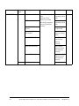
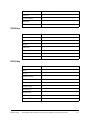
The following table shows the video connector.
Connector
Interface type
SMPTE 292M
Connector type
BNC female
To Connect the Composite Video Ouput
Do as follows to connect to the Composite Video Output:
1. Connect a video monitor to the CVSB 1 and CVSB2 connectors. The two outputs
are identical.
Use a 75-ohm double-braided coax cable.
3-8
Model D9858 Advanced Receiver Transcoder Installation and Operation Guide
4023074 Rev B
Connecting the Audio Outputs
To Connect the Balanced Audio Output
1. Connect the AUDIO 1 and AUDIO 2 balanced audio outputs to monitoring
equipment. Use a multi-conductor, pluggable cable from the transcoder's
AUDIO 1 and AUDIO 2 (Left and Right) terminals to your equipment, as shown
in the following illustration.
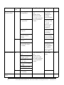
Connector
Connector type
Terminal Block
2. Feed the stripped ends of the positive, negative and ground wires into the
appropriate terminals as labelled, and then screw the terminal screws (located
on the top of the terminal block) finger tight to each wire.
4023074 Rev B
Model D9858 Advanced Receiver Transcoder Installation and Operation Guide
3-9
Connecting the Ethernet Management Interface
The Ethernet Interface
The RJ-45 interface for 10/100/1000BaseT Ethernet is currently intended for
upgrading/downloading the software application.
Hint: If you experience problems with the 10 BaseT Ethernet it is advised that you
change it to a 100 BaseT connection.
Note: You must set up the IP address, the default gateway and the subnet mask to
match the network connection. This is done through the front panel menu. For
further information, see IP, page 4-35.
Informative Notes
Proper cables are required for reliable Ethernet operation; to run over a maximum
segment length of 100 m the cable has to comply with the EIA/TIA Category 5E
wire specifications.
To Connect the Ethernet Interface
1. Connect a crossed RJ-45 cable between the Ethernet connector on the D9858
Advanced Receiver Transcoder and the Ethernet port of your PC.
Note: You need a crossover cable if you want to connect the Ethernet interface of
the D9858 Advanced Receiver Transcoder directly to another Ethernet device
without using a hub or switch.
You need to set up the IP address on the D9858 Advanced Receiver Transcoder (via
the front panel display). For information on setting up the IP address via the front
panel, see IP, page 4-35.
3-10
Model D9858 Advanced Receiver Transcoder Installation and Operation Guide
4023074 Rev B
Connecting the IP TS Output
The Ethernet Interface
The RJ-45 interface IP TS OUT is 10/100/1000BaseT Ethernet. It is intended for
output of the transport stream encapsulated in IP packets to a groomer (e.g., Digital
Content Manager 9900) for distribution.
Informative Notes
For reliable Ethernet operation; to run over a maximum segment length of 100 m
the cable has to comply with the EIA/TIA Category 5E wire specifications.
To Connect the Ethernet Interface
1. Connect a crossed RJ-45 cable between the Ethernet connector on the D9858
transcoder and the Ethernet port of the equipment after the D9858 transcoder.
The equipment after the D9858 Transcoder could be an IP router or a switch.
4023074 Rev B
Model D9858 Advanced Receiver Transcoder Installation and Operation Guide
3-11
Connecting the ASI Outputs
To Connect the ASI Output
Do as follows to connect to the ASI outputs:
1. Connect the output signal from the D9858 Advanced Receiver Transcoder ASI
OUT connectors. All three outputs, ASI OUT 1, 2 and 3 are identical.
2. Use a Belden “Brilliance“ cable with foil/braid construction. The shield must
provide 99% or better shielding effectiveness.
The equipment after the D9858 Advanced Receiver Transcoder could be a
Model D9887 HDTV Modular Receiver or Model D9854 Advanced Program
Receiver.
3-12
Model D9858 Advanced Receiver Transcoder Installation and Operation Guide
4023074 Rev B
Connecting an External Alarm System
Connector for an External Alarm System
The D9858 Advanced Receiver Transcoder is equipped with a connector labeled
Cue Tone/Relay which provides alarm relay outputs for remote alarm signaling.
This connector provides Cue Tone, Cue Trigger and Alarm relay functionality. See
Pin allocation, RS-232 Data connector, page 3-14 for more information on Cue
Tone and Cue Trigger equipment connections. These outputs are user-configurable
via the Setup Menu on the front panel.
The Alarm output connector is a 15-pin sub-D female connector. The following
diagram shows the connector and the pin allocation table for the Alarm output pins.
Connector
Normally
closed pin
Common
pin
Normally
open pin
11
10
15
1. Connect the cable from the external alarm system to the alarm connector.
4023074 Rev B
Model D9858 Advanced Receiver Transcoder Installation and Operation Guide
3-13
Connecting the RS-232 Data Interface
The RS-232 Data Interface
The DCE DB-9 female connector is intended for low-speed data: 7 bits, even parity,
1 stop bit, up to 38.4 kbps (default). These outputs are user-configurable via the
Setup Menu on the front panel.
The interconnect cable from the D9858 transcoder to a PC should be straight
through (i.e., no handshaking), shielded and equipped with a DB-9 male connector
at one end to mate with the rear panel RS-232 Data interface, and a female DB-9
connector to connect to the PC.
Pin Allocation, RS-232 Data Connector
The table shows the RS-232 Data connector and the pin allocation:
Connector
Pin
1
9
3-14
Pin allocation
1
Not connected
2
TxD
3
RxD
4
Not connected
5
Ground
6
Not connected
7
Not connected
8
Not connected
9
Not connected
Model D9858 Advanced Receiver Transcoder Installation and Operation Guide
4023074 Rev B
Chapter 4
Front Panel Operation
Overview
Introduction
This chapter describes how to set up the D9858 Advanced Receiver Transcoder
using the front panel keys and display. This information is primarily applicable for
standalone operation.
In This Chapter
This chapter contains the following topics.
Topic
4023074 Rev B
See Page
About the Front Panel
4-2
Keypad Convention
4-4
Startup Screen
4-6
Main Menu
4-10
Status Menu
4-11
Setup Menu
4-21
About Menu
4-81
Versions Menu
4-83
Diagnostics Menu
4-85
Model D9858 Advanced Receiver Transcoder Installation and Operation Guide
4-1
About the Front Panel
Introduction
The D9858 transcoder is operated using controls and indicators on the front panel.
These include the numeric keypad, the Navigation/Selection keypad, the LCD, the
Alarm and Signal indicators. These are shown in the following illustration.
LCD Panel
Alarm LED Signal LED
Navigation/Selection
Numeric Keypad
LCD
The LCD provides information on the selections available at any menu level,
current settings for parameters, and certain status and alarm indications. This is a
2x40, backlit LCD display. The top line may be status data or identifier information.
It can also display optional functions available for tuning operations. The bottom
line will show selections or parameter values available using the navigation/
selection keypad. The items are selected by pressing the SELECT (center key) or
DOWN arrow key on the navigation/selection keypad.
Keypad
The numeric keypad is used to enter alphanumeric values. The MENU key sets the
software to the initial menu and returns you to the previous menu. The MENU key
can also be used to cancel a numeric entry at any point during the entry sequence,
and the LEFT arrow key allows backspacing through the entry.
4-2
Model D9858 Advanced Receiver Transcoder Installation and Operation Guide
4023074 Rev B
About the Front Panel, Continued
Front Panel LEDs
The functions of the LEDs are described in the table below.
LED
ALARM
Signal
State/Color
Explanation
Red
Solid for five seconds indicates a Warning.
Red
Flashing indicates an Alarm.
Green
Solid indicates all of the following conditions:
• all RF inputs are enabled, all inputs are locked to a
signal, and are not muted.
• all outputs are operating without an error.
Green
Flashing indicates one of the following conditions:
• difficulty with an input or output.
• one or more RF inputs, or the ASI input are not
synchronized.
• one or more outputs are muted by a fault condition.
• no RF signal is present or detected, or it is muted.
• receiver is not authorized to receive the program.
Off
Off indicates all of the following conditions:
• no RF input signal is available, enabled or detected, or
the input is muted.
• no ASI input is present
• no valid inputs are available.
SIGNAL
Navigation/Selection Keypad
The navigation keys (LEFT, RIGHT, UP and DOWN) and the SELECT key are the
primary controllers. Each navigation key performs various functions, depending on
the current state of the menu system (i.e., sometimes the left navigation key
backspaces over an entry and sometimes moves the cursor to a different menu
item). Once the cursor is over the desired function, pressing the SELECT (center
key) key selects the current item. Pressing the SELECT key stores any entered
values.
4023074 Rev B
Model D9858 Advanced Receiver Transcoder Installation and Operation Guide
4-3
Keypad Convention
Overview
Throughout this manual, there are references to parts of a
keypad on the front of the transcoder. This is the
Navigation/Selection keypad (see diagram at right), which
changes its function, depending on the current state of the
menu. For clarity, the following table shows which parts of
this integral interface are being referenced by which term.
Keypad Button
SELECT
Runs the highlighted command or opens the highlighted menu.
LEFT arrow
When moving through menus, highlights the menu item to the
left. When entering data, moves the cursor to the left. In some
menus, backspaces over the data entry.
UP arrow
Highlights the menu item above.
RIGHT arrow
When moving through menus, highlights the menu item to the
right. When entering data, moves the cursor to the right.
DOWN arrow
Highlights the menu item below.
Key
LEFT arrow
RIGHT arrow
UP arrow
DOWN arrow
SELECT
4-4
Function
Function
Press the key on the left side of the
Navigation/Selection Keypad.
Press the key on the right side of the
Navigation/Selection Keypad.
Press the key on the top of the
Navigation/Selection Keypad.
Press the key on the bottom of the
Navigation/Selection Keypad.
Press the key in the center of the
Navigation/Selection Keypad.
Keypad Button
Model D9858 Advanced Receiver Transcoder Installation and Operation Guide
4023074 Rev B
Keypad Convention, Continued
Key
INFO
Function
Press the key on the lower
left of the numeric keypad
for context-sensitive help
messages, when available.
When entering characters in
numeric or alphanumeric
fields, this key can be used
to toggle between upper
and lower case.
MENU
Alphanumeric Entry
ADV
MAP
APPLY
NAV
4023074 Rev B
Keypad Button
1
2 ABC
3 DEF
ADV
4 GHI
5 JKL
6 MNO
MAP
7 PQRS
8 TUV
9WXYZ
APPLY
INFO
0
MENU
NAV
Press the key on the lower right of
the numeric keypad.
Starts the on-screen display. Also
functions as the Escape key so you
can back out of menus and data
entry fields.
Pressing the numeric keys 2-9 once
will enter the respective digit into a
data entry field. Pressing these
buttons again will enter the first of
the letters displayed beside the
number. Repeatedly pressing the
button will toggle through all of
that key's possible choices.
When entering text, the 1 button can
be used to insert spaces (press
twice).
To delete a character, press 0 twice.
Toggles between Program Entry
and Channel number.
Edit, insert and delete Digital
Program Mapping (DPM) Modes on
Program Entries or on PIDS within
Program Entries.
Activates current changes without
having to exit the menu.
For future use.
Model D9858 Advanced Receiver Transcoder Installation and Operation Guide
4-5
Startup Screen
Menu Structure
On power-up and initialization, the startup screen is displayed similar to that
shown below. The screen also indicates the signal status.
s
PE1 12345 Channel Name
RF1
Freq:12.658 Lvl:100 Marg:9.9e-9
Startup Screen
PE: 1 2
Auth:Y Y
Channel Authorization Status Screen
Channel Authorization Status
From the startup screen, press the right or left arrow keys on the front panel keypad
to move to the PE entry authorization status screen. This screen indicates whether
the decode channel and other selected channels are authorized.
Auth Status
Description
Y
Indicates the channel is authorized.
N
Indicates the channel is not authorized.
LCD Panel
The LCD panel displays basic signal and program information in the LCD display,
as described in the following illustration:
Hourglass
s
PE1 12345 Channel Name
RF1
Freq:12.658 Lvl:100 Marg:9.9e-9
LCD Setting
4-6
Description
PE
PE. The transcoder supports two Program Entries (PE1 and
PE2). PE1 is the decode channel and is available at the
analog outputs. PE2 is available for the second transcoded
channel on the ASI output.
12345
Channel for program monitoring.
Channel name
Name of the monitored program.
Model D9858 Advanced Receiver Transcoder Installation and Operation Guide
4023074 Rev B
Startup Screen, Continued
LCD Setting
Description
RF
Active RF input port. Note: ASI will be shown if the ASI
input port is active.
Freq:
Downlink frequency of the tuned signal in GHz
Lvl:
Signal level
Marg:
Carrier-to-noise (C/N) margin in dBm
Hourglass
Indicates that parameters are being saved in the
background. You can continue to perform any operation
desired.
Note: If a power- cycle/interruption occurs while the
hourglass is displayed, some parameters may not be saved.
Refrain from powering off the unit while the hourglass is
displayed.
Assigning a Program Channel to a Program Entry
To assign a program to a Program Entry:
1. Press MENU until you display the startup screen.
PE1 (the decode Program Entry) is initially displayed.
2. Press the ADV key on the front panel keypad and then the UP or DOWN arrow
keys to scroll through the PEs available.
3. Press the SELECT key to select a PE (PE1 or PE2) and then the RIGHT arrow key
to move to the right and scroll through the available program channels.
PE # Ch #
PE1
RF1
4023074 Rev B
s
706 Channel Name
Freq:12.658 Lvl:100 Marg:9.9e-9
Model D9858 Advanced Receiver Transcoder Installation and Operation Guide
4-7
Startup Screen, Continued
4. Directly enter the channel number using the 0 to 9 keys), followed by the
program channel for the selected PE.
5. Repeat this process to select a program channel for the two PEs, PE1 and PE2.
Deleting a Program from a Program Entry
To delete a program:
1. Press MENU until the startup screen appears.
PE
Ch #
PE1 1
Channel Name
RF1
Freq:12.658 Lvl:100 Marg:9.9e-9
s
2. Navigate to the PE and the program that you want to delete.
PE # Ch #
PE1
RF1
s
706 Channel Name
Freq:12.658 Lvl:100 Marg:9.9e-9
3. Press SELECT to select the program number.
4. Press MAP to delete the program or alternatively enter program number 0 in the
PE entry to delete it. You can also use the MAP key to re-insert a program after
you have deleted it by simply pressing MAP again.
Program Entry Output Mode
A program can be set to one of four output modes, either Drop, Pass, Map, or
XCode respectively.
LCD Setting
4-8
Description
Drop
Removes the service and its associated PMT reference from
the transport output.
Pass
Permits the source content and PMT reference to appear in
the transport output with the same references unless the
source material is MAPped on another PE.
Model D9858 Advanced Receiver Transcoder Installation and Operation Guide
4023074 Rev B
Startup Screen, Continued
LCD Setting
Description
Map
Provides the flexibility to define all the outgoing PID
numbers for a PE, including those not currently on
transmission.
XCode
Provides the flexibility to define all the outgoing PID
numbers for a PE, including those not currently on
transmission, as in Map mode, plus the video PID is
transcoded to output at the rate and settings defined for the
transcode channel.
See PE Resync: All, Template, PIDs, Svcs, page 4-64 and Setting Up Transcoding,
page 4-71 for more information.
4023074 Rev B
Model D9858 Advanced Receiver Transcoder Installation and Operation Guide
4-9
Main Menu
Structure
Operation of the D9858 Advanced Receiver Transcoder begins at the Main menu.
From the startup screen, press the MENU key to view the Main menu.
Main Menu
Status Setup About Versions
1/2
Main Menu
i s
2/2
i s
Diagnostics
Menu Selection
Select the desired function by moving the cursor left or right by pressing the LEFT
or RIGHT arrow key. Once a selection is made by pressing the SELECT key, the
LCD presents the second menu level for the selected function. Succeeding levels for
each function include all the heirachical levels for the function in the front panel
LCD. For example, the TS Input level is shown as Main: Setup: TS Input, with each
succeeding level separated by a colon (:), as shown in the example below. The front
panel menus are described on the following pages.
Main Menu
Status Setup About Versions
1 st level
Main:Status
General Services TS Input TS Output
2 nd level
3 rd level
4-10
i s
i s
Main:Setup
Admin TS Input IP Services
Main:Setup:TS Input
Input Tune Mode
1/2
1/2
i s
Main:Setup
2/2
Outputs CA Alarm/Warning NoiseCutoff
i s
i s
Model D9858 Advanced Receiver Transcoder Installation and Operation Guide
4023074 Rev B
Status Menu
Structure
To view the Status menu from the Main menu, press the SELECT key. The Status
menu indicates the status of the input and output signals, the video and audio
services, and allows you to browse and/or configure the alarms and warnings.
The Status menu is split into four parts; General, Services, TS Input and TS Output.
Each parameter is described in this section. For instructions on how to select and
store settings, see About the Front Panel, page 4-2.
The Status menu has the following structure:
Main:Status
General Services TS Input TS Output
i s
Main:Status:TS Input
Input Program PIDs
i s
General Status
Input Status
Rate(Mbps) Level(dBm) i
RF1
Lock+Sig 68.987654 100
Main:Status:TS Output
Output
i s
CASys Mode Auth Enc Scr CaResource i
Irdet BISS1 Yes Yes Yes ISE00011122
Video
H.264 HD1080i/3000
Alarms
0
Warnings
0
Rate(Mbps)
10.991234
Browse
Clear All
Warning Set on 2007/02/09 10:01:05
Loss of Signal
i
Input Status
Input Status
Rate(Mbps) Level(dBm) i
RF1
Lock+Sig 68.987
100
i
SymRate FEC Modulation
IQ
Pol i
30.5001 Auto DVB-S2/16QAM NonInv H
i
Dnlk Freq(GHz) L-Band
15.000000
1640.0
C/N(dB)
19.3
Main:Status:Services
Video Audio
3:2 Pulldown
Recent
Stream AR
221:100
Rate(Mbps)
10.9912
FPS
29.997
Free(Mbps)
25.999999
i
Pilot Present i
Yes
C/N Margin(dB)
12.0
i
i s
PER
0
Video Status
Video
H.264 HD1080i/3000
Output Status
Output
Rate(Mbps)
MOIP1
49.999999
PVBER
0.00e-6
LDPCBER
0.00e-6
i
i
AFC Uncorr Err Cnt
1234 0
Corr Err Cnt
408
i
ASI Link
Error
Packet Size
n/a
i
i
Act Conv
16:9 F/W
Transport
Error
i
NetName
x
Audio Status
AUD Format BR(kbps) Buffer SFR(Hz)
1
HE-ACC 384
7250
48000
i
NetID TxID
3
301
i
LNB Stat
LNB Power
No Connect Off
i
Polar
Auto
i
LO Select
Off
Program PIDs
PE Name Type Detail
PID Present i
1 <SUBT1 SUBT MPG2 VID 8191 Yes
>
4023074 Rev B
Model D9858 Advanced Receiver Transcoder Installation and Operation Guide
4-11
Status Menu: General
GENERAL
Input
Description:
Indicates the active input port receiving the signal.
Description:
Indicates the current signal lock status for the selected RF input.
Parameters:
Signal Lock - see table.
Status
Status
Description
Locked
Indicates the transcoder is locked to a
carrier with no valid content.
Lock+Sync
Indicates the transcoder is locked to a
carrier with valid content.
No Lock
Indicates the transcoder is not locked to a
carrier.
Rate
Description:
Indicates the bit rate of the received input signal
Parameters:
Mbps.
Description:
Indicates the signal level of received signal.
Parameters:
dBm.
Description:
Indicates the Conditional Access (CA) system used for the received
signal.
Parameters:
SA or BISS.
Description:
Indicates the type of CA used for the received signal, e.g., SA or
BISS.
Description:
Indicates whether the transcoder is authorized to receive the signal.
Parameters:
Yes or No.
Level
CASys
Mode
Auth
4-12
Model D9858 Advanced Receiver Transcoder Installation and Operation Guide
4023074 Rev B
Status Menu: General, Continued
Enc
Description:
Indicates whether the received signal is encrypted.
Parameters:
Yes or No.
Description:
Indicates whether the received signal is scrambled.
Parameters:
Yes or No.
Description:
Indicates the Conditional Access resource associated with the
program.
Parameters:
FTA, SA or Auto.
Scr
CAResource
FTA - Free to Air
SA - Scientific Atlanta proprietary conditional access
Video
Description:
Indicates the input stream type and source resolution of the
received signal/program.
Parameters:
SD480i/2997, SD480i/3000, SD576i/2500, HD720p/5000, HD720p/
5994, HD720p/6000, HD1080i/2500, HD1080i/2997, HD1080i/
3000, Unknown or Unsupported.
Description:
Indicates the bit rate of the received video program.
Description:
Displays the number of currently active Alarms.
Description:
Indicates the number of currently active Warnings.
Description:
Select this option to scroll through the current alarms and warnings.
Description:
Select this option to clear all the current warnings and alarms. You
will be prompted to verify whether you want to clear all the alarms
and warnings.
Parameters:
Abort, Continue. Select Abort to cancel the operation or Continue to
clear all the warnings and alarms.
Rate
Alarms
Warnings
Browse
Clear All
4023074 Rev B
Model D9858 Advanced Receiver Transcoder Installation and Operation Guide
4-13
Status Menu: Services
SERVICES
VIDEO
Video
Description:
Indicates the input stream type and source resolution of the
received signal/program.
Parameters:
SD480i/2997, SD480i/3000, SD576i/2500, HD720p/5000, HD720p/
5994, HD720p/6000, HD1080i/2500, HD1080i/2997, HD1080i/
3000, Unknown or Unsupported.
Description:
Indicates the bit rate of the received video program.
Description:
Indicates whether 3:2 pulldown mode is detected.
Parameters:
Yes, No or Recent.
Description:
Indicates the frame rate in frames per second.
Description:
Indicates the stream aspect ratio. This is the conversion that the
transcoder will perform on the incoming signal for the picture to be
displayed correctly (i.e., to correspond to the aspect ratio of your
TV) on your TV, based on your selection.
Parameters:
4:3, 14:9 or 16:9.
Description:
This is the type of aspect ratio conversion that the transcoder will
perform based on your selection.
Parameters:
None, 4:3 L/B, 4:3 P/B, 14:9, 14:9, 4:3 F/H, or 16:9 F/W.
Description:
Indicates the audio channel within the stream when the signal
contains more than two audio pairs.
Parameters:
AUD1 for audio channel Aud1.
Rate
3:2 Pulldown
FPS
Stream AR
Act Conv
AUDIO
AUD
AUD2 for audio channel Aud2.
AUD1 to AUD4 for two stereo audio channels.
Format
4-14
Description:
Indicates the received audio channel format.
Parameters:
MPEG, AC3, AAC, HEAAC or DDP.
Model D9858 Advanced Receiver Transcoder Installation and Operation Guide
4023074 Rev B
Status Menu: Services, Continued
BR
Description:
Indicates the audio bit rate of the received audio channel.
Parameters:
Kbps.
Description:
Indicates the audio input buffer level.
Parameters:
bytes.
Description:
Indicates the audio sampling frequency.
Parameters:
32, 44.1 or 48 kHz.
Description:
Indicates the active input port receiving the signal.
Parameters:
RF1, RF2, RF3, RF4 or ASI.
Description:
Indicates the current signal lock status for the input.
Parameters:
Signal Lock - see table.
Buffer
SFR
TS INPUT
INPUT
Input
Status
Status
Description
Locked
Indicates the transcoder is locked to a
carrier with no valid content.
Lock+Sync
Indicates the transcoder is locked to a
carrier with valid content.
No Lock
Indicates the transcoder is not locked to a
carrier.
Rate
Description:
Indicates the bit rate of the received input signal.
Parameters:
Mbps.
Description:
Indicates the signal level of received signal.
Parameters:
dBm.
Level
4023074 Rev B
Model D9858 Advanced Receiver Transcoder Installation and Operation Guide
4-15
Status Menu: TS Input
SymRate
Description:
Indicates the Symbol Rate of the received signal.
Parameters:
Msymbols/second.
Description:
Indicates the FEC (Forward Error Correction) rate of the received
signal.
Parameters:
N/A, 1/2, 2/3, 3/4, 5/6, 7/8, 8/9 or Auto.
Description:
Indicates the modulation type for the received signal.
Parameters:
N/A, QPSK, 8PSK, DVB-S or DVB-S2.
Description:
Indicates the IQ (Input Signal Inversion) for the received signal.
Parameters:
Inv, NonInv or Auto.
Description:
Indicates the signal polarization setting. This setting is only
applicable when LNB Power is set to H-NIT or V-NIT. The selected
setting must match the polarization of the transmitted signal.
Parameters:
Hor, Vert or Auto.
Description:
Indicates the current downlink frequency.
Parameters:
GHz.
Description:
Indicates the current L-Band frequency.
Parameters:
MHz.
Description:
Indicates whether a Pilot is present for the received signal. The Pilot
is set on the modulator for input signal synchronization purposes.
Parameters:
Yes or No.
Description:
Indicates the current Carrier-to-Noise rate.
Parameters:
dBm.
Description:
Indicates the current Carrier-to-Noise Margin for the received
signal. The Carrier-to-Noise margin is the actual distance that C/N
is from the noise threshold.
FEC
Modulation
IQ
Pol
Dnlk Freq
L-Band
Pilot Present
C/N
C/N Margin
4-16
Model D9858 Advanced Receiver Transcoder Installation and Operation Guide
4023074 Rev B
Status Menu: TS Input, Continued
Parameters:
dBm.
Description:
Indicates the current PER (Packet Error Rate).
Parameters:
bps.
Description:
Indicates the PV (Post-Viterbi) BER for the received signal (DVB-S)
and LDPC for the selected input (DVB-S2).
Parameters:
bps.
Description:
Indicates the current Automatic Frequency Control count.
Description:
Indicates the current Uncorrected Error Count for the received
signal.
Description:
Indicates the current Corrected Error Count for the received signal.
Description:
Select this option to clear the error counters. You will be prompted
to confirm the operation.
Parameters:
Yes, No.
Description:
Indicates the name assigned to the network.
Parameters:
Up to 12 alphanumeric characters.
Description:
Indicates whether there is a transport stream link error.
Parameters:
Yes, No or N/A.
Description:
Indicates the current transport synchronization status
Parameters:
Sync - No Sync, Normal or N/A.
Description:
Indicates the packet Size (in bytes) for the selected input.
Parameters:
188 bytes or 204 bytes.
PER
PVBER
AFC
UEC
CEC
Clear Counts
Net Name
ASI Link
Transport
Packet Size
4023074 Rev B
Model D9858 Advanced Receiver Transcoder Installation and Operation Guide
4-17
Status Menu: TS Input, Continued
NetID
Description:
Indicates the Network ID of the uplink signal the transcoder is to
receive when using the selected preset. The transcoder’s Network
ID must match the Network ID associated with the transmitted
signal that identifies the NIT to be used.
Note: Each network must be assigned a unique ID (number).
Parameters:
1 to 65535.
Description:
Indicates the Transport ID.
Parameters:
1 to 65535.
Description:
Indicates the current LNB connection status.
Parameters:
Overload, OverTemp, No Connect, Normal or N/A.
Description:
Indicates the LNB voltage at the received input port.
Parameters
Off, 13V or 18V.
Description:
Indicates the polarity of the received signal.
Parameters:
Hor, Vert or Auto.
Description:
Indicates whether a 22 kHz tone is available on input port RF1. This
is applicable for dual-band applications.
Parameters:
On, Off or Auto.
TxID
LNB Stat
LNB Power
Polar
LO Select
PROGRAM PIDS
PE
Description:
Indicates the Program Entry number.
Parameters:
1 to 4.
Description:
Indicates the name assigned to the Program Entry.
Parameters:
Up to 4 alphanumeric characters.
Description:
Indicates the type of program associated with incoming PID.
Parameters:
PMT, PCR, VID, AUD, SUBT, CDT, ECM, EMM, DATA, MPE, VBI
or DPI.
Name
Type
4-18
Model D9858 Advanced Receiver Transcoder Installation and Operation Guide
4023074 Rev B
Status Menu: TS Input, Continued
Detail
Description:
Indicates any detail associated with the program PID (e.g., MPG2
PID).
Parameters:
MPG1 VID, MPG2 VID, 422 VID, H264 VID, HD VID, MPG4 VID,
MPG AUD, MPG2 AUD, DVB AC3, DVB DDP, AAC AUD,
HEAAC, AUD, MPG4 AUD, DBE AUD, DTS AUD, DVB TXT, DVB
VBI, DVB SUBT, DVB ASYN, DVB SYNS, DVB SYND, DVB MPE,
DVB DCAR, DVB OCAR, SA VBI, ATSC AC3, ATSC DDP, SA
UTLD, SCTE DPI, SA HSD, SA CDDL, SA WBD, SA SUBT, ECM,
EMM, PCR, or UNKNOWN.
Description:
Indicates the program PID number.
Parameters:
1 to 8192.
Description:
Indicates whether the PID is present in the incoming stream.
Description:
Indicates the output type.
Parameters:
ASI or MPEGoIP.
Description:
Indicates the current output bit rate.
Parameters:
0 to 213 Mbps.
Description:
Indicates the available bit bandwidth (no stuffing).
Parameters:
Mbps.
PID
Pres
TS OUTPUT
OUTPUT
Output
Rate
Free
OUTPUT PIDS
PROGRAM PIDS
PE
Description:
Indicates the output Program Entry number.
Parameters:
1 to 4.
Description:
Indicates the name assigned to the Program Entry.
Parameters:
Up to 4 alphanumeric characters.
Name
4023074 Rev B
Model D9858 Advanced Receiver Transcoder Installation and Operation Guide
4-19
Status Menu: TS Output
Type
Description:
Indicates the type of program associated with incoming PID.
Parameters:
PMT, PCR, VID#1, AUD#, SUBT, CDT, ECM, EMM, DATA, MPE,
VBI or DPI.
Description:
Indicates any detail associated with the output PID.
Parameters:
MPG1 VID, MPG2 VID, 422 VID, H264 VID, HD VID, MPG4 VID,
MPG AUD, MPG2 AUD, DVB AC3, DVB DDP, AAC AUD,
HEAAC, AUD, MPG4 AUD, DBE AUD, DTS AUD, DVB TXT, DVB
VBI, DVB SUBT, DVB ASYN, DVB SYNS, DVB SYND, DVB MPE,
DVB DCAR, DVB OCAR, SA VBI, ATSC AC3, ATSC DDP, SA
UTLD, SCTE DPI, SA HSD, SA CDDL, SA WBD, SA SUBT, ECM,
EMM, PCR or UNKNOWN.
Description:
Indicates the program PID number.
Parameters:
1 to 8192.
Description:
Indicates whether the PID is present in the incoming stream.
Parameters:
Yes or No.
Detail
PID
Pres
4-20
Model D9858 Advanced Receiver Transcoder Installation and Operation Guide
4023074 Rev B
Setup Menu
Structure
To view the Setup menu from the Main menu, press the RIGHT arrow key once and
the SELECT key. The Setup menu is split into eight parts; Administration, TS Input,
IP, Services, Outputs, CA, Alarms/Warnings, and Noise Cutoff. For instructions on
how to select and store settings, see About the Front Panel, page 4-2.
The Setup menu allows you to set all the parameters associated with the following:
• Administration - lock level, password, factory reset, keypad lock, download
mode and date and time
• TS Input - frequency parameters for acquiring and locking on to an RF signal, or
receiving an ASI input
• IP - parameters for setting up the Ethernet ports
• Services- audio video, captions, and VBI
• Outputs - parameters for setting up the transport stream out, which includes
DPM and transcoding
• CA - conditional access
• Alarms/Warnings - enables alarms/warnings traps and relays
• Noise Cutoff - muting thresholds
The Setup menu has the following structure:
Main:Setup
Admin TS Input IP Services
4023074 Rev B
1/2
i s
Main:Setup
2/2 i
Outputs CA Alarm/Warning NoiseCutoff
Model D9858 Advanced Receiver Transcoder Installation and Operation Guide
s
4-21
Setup Menu: Admin
Structure
To view the Admin menu from the Main menu, press the SELECT key.
For instructions on how to select and store settings, see About the Front Panel,
page 4-2.
The Admin menu has the following structure:
Admin
Lock Level Password
[0]
[
]
Old Pwd
New Pwd
Factory Reset
i s
Confirm Pwd
i s
Clear FWD Tables
i s
Reboot Unit
i s
KB Lock
Disabled
i s
KB Lock Timeout
1200
Validate OrbPos
DL Mode
FPGA Once
LCD Contrast
[30]
DL FPGA
Disable
Limit Version
1.01.01
DL Status Type
Running
UnforcedPMT
CDT#
8417
Recv
8417
Reject
0
Bank
Application
Command
[Restart]
i s
i s
i s
i s
Date Format Time Format
GMT Off i
[MM_DD_YYYY][24Hr SuspendZero]+12:00]
D9858 Menu
[Disabled]
Reset Login Table
4-22
s
i s
i s
Model D9858 Advanced Receiver Transcoder Installation and Operation Guide
4023074 Rev B
Setup Menu: Admin, Continued
Lock Level
Description:
Sets the front panel keypad lock level.
Parameters:
0, 1, 2, 3 or 4.
Changing the Password
To change the password, enter the old password (Old Pwd). Next,
enter the new password (New Pwd, four digits in the range from
0000 to 9999) and re-enter the new password for confirmation
(Confirm Pwd). To change the password, the transcoder must be in
Lock Level 0. The default password is 1234.
Factory Reset
Description
Select this option to perform a reset of transcoder settings back to
the factory set (default) values. A warning message prompts you to
confirm the operation.
Parameters:
Reboot Unit - you are prompted to verify the operation.
Abort or Continue.
Clear FWD tables
Description
Select this option to Clear the Forward Tables, which removes
stored database information applicable to upgraded software
versions. A warning message prompts you to confirm the
operation.
Parameters:
Abort or Continue.
Description:
Allows you to reboot the transcoder. You will be asked to confirm
the operation.
Reboot
Parameters: Abort or Continue. Select Continue to reboot the
transcoder or Abort to cancel the operation.
KB Lock
Description
Sets the front panel keypad lock state.
Parameters:
Enabled or Disabled.
KB Lock Timeout
4023074 Rev B
Description:
Sets the keypad lock timeout period. The lock timeout period takes
effect when the keypad has not been touched (i.e., a key has not
been pressed) when on the Main Menu for the set period. Avoid
setting the period to a short duration when the keypad is used
often.
Parameters:
5 to 1800 seconds. The default is 60 seconds.
Model D9858 Advanced Receiver Transcoder Installation and Operation Guide
4-23
Setup Menu: Admin, Continued
LCD Contrast
Description
Adjusts the contrast of the LCD menu panel.
Parameters:
1 (lowest contrast) to 30 (highest contrast).
Description
Sets the download mode.
Parameters:
FPGA Once, Always or Never.
DL Mode
DL Mode Setting
Description
Always
Unforced download will be
accepted and saved in memory.
FPGA Once
An unforced download will be
accepted, followed by a reboot of
the transcoder, and the DL Mode
will change to Never.
Never
Unforced downloads will not be
accepted.
Note: Forced downloads (initiated by the uplink) are always
accepted and always result in a reboot of the transcoder. Service
interruption will occur!
DL FPGA
Description
Sets the FPFA download mode.
Parameters:
Enable or Disable.
DL Status, Type, Bank
Description
Indicates the DL Mode status, type and bank (i.e., type of code).
Parameters:
DL Status - Idle, Running, Timeout. Idle indicates the transcoder is
waiting for a download. Running indicates the transcoder is
processing a download. Timeout indicates the transcoder didn’t
complete the download.
Type - rearpanel is only supported at present.
Bank - the type of code, either Application or FPGA.
Limit Version
4-24
Description
Indicates the current FPGA version number.
Parameters:
Read-only alphanumeric value.
Model D9858 Advanced Receiver Transcoder Installation and Operation Guide
4023074 Rev B
Setup Menu: Admin, Continued
CDT#
Description:
Indicates the total number of expected CDTs, the number received,
the number rejected and the download command.
Parameters:
This is the number of tables expected to be received during the
current download operation.
Description:
This is the number of CDTs received since the last completed or
aborted download, or power-cycle.
Parameters:
Read-only numeric value.
Description:
This is the rejected table count. Tables are rejected whenever
validation fails due to things like CRC failure or incorrect code or
transcoder type.
Parameters:
Read-only numeric value.
Description:
Indicates the download command.
Parameters:
Restart, Abort or None. Abort stops a download that is currently
being received. Restart restarts a previously aborted download.
Note that the download does not resume from where it was
aborted, but restarts from the beginning. None means no action is to
be performed.
Recv
Reject
Command
Date Format, Time Format
Description:
Sets the Date and Time formats and the GMT offset. Time
information is normally broadcast as part of the transmitted digital
signal. It is usually the broadcasters local time relative to GMT
(Greenwich Mean Time).
Parameters:
Date - The following formats are supported: YYYY_MM_DD,
DD_MM_YYY, MM_DD_YYYY, MM_DD, INVALID.
Time - The following formats are supported: 24Hr, 24Hr
SuspendZero the (leading zero is dropped from the time), 12Hr,
12Hr SuspendZero (the leading zero is dropped from the time).
GMT Off - Time is displayed using a time zone instead of the true
local time. If the current broadcast time is not your local time, you
must change this time setting in the range from -12.0 to +12.0 hours
in 0.5 hour increments.
D9858 Menu
Description:
4023074 Rev B
Sets whether to display the onscreen banner message after booting
up the transcoder.
Model D9858 Advanced Receiver Transcoder Installation and Operation Guide
4-25
Setup Menu: Admin, Continued
Parameters:
Enable or Disable. The default is Disable.
Reset Login Table
Description:
Sets whether to reset the login table to the factory set defaults.
Parameters:
Abort or Continue.
Abort cancels the reset operation.
Continue resets all the values in the login table to their defaults (i.e.,
factory set values).
4-26
Model D9858 Advanced Receiver Transcoder Installation and Operation Guide
4023074 Rev B
Setup Menu: TS Input
Structure
To view the TS (Transport Stream) Input menu from the Main menu, press the
RIGHT arrow key once and then the SELECT key to reach the Setup menu. Then
press the RIGHT arrow key once and the SELECT key to view the TS Input menu.
For instructions on how to select and store settings, see About the Front Panel,
page 4-2.
The TS Input menu has the following structure:
Main:Setup:TS Input
Input Tune Mode
Main:Setup:TS Input:Input
ASI RF1 RF2 RF3 RF4
ASI Input
i s
Main:Setup:TS Input
Custom Status
i s
i s
RFx Input
Tune Mode Status
ASI Active Tune Mode CA Ctl Select
[Act]
[FixPID] [Open] [RF Map]
i s
RFx Active Tune Mode CA Ctl Select i
[Act]
[FixPID] [Open] [RF Map]
s
Service List Mode
Rigorous
LNB Type
LNB Trim1 LNB Trim2
[Single Ku][ 0.00
][ 0.00
]
i s
LO1(GHz)
LO2(GHz)
Xover(GHz)
[10.75
][10.75
][12.00
]
i s
Satellite
Yamal 102
OrbPos E/W Pol
[ 90.0] [NA] [H]
BAT NIT SDT PAT
Yes Yes Yes Yes
Frequency Tuning
Preset
Custom Setup
Service List Mode
[Rigorous]
i
BAT NIT SDT PAT i
Yes[Yes]Yes]Yes]
Frequency Tuning
[Preset]
i s
Orbital Position Validation Date
2008/04/01 12:43:56
i
Ch Srvc PID
Type
Ins
[16][14] [8192][MPEG VID]
Freq(GHz) SymRate FEC L-Band RFLock i
[15.000000]28.3465]Auto]1640.0 No Loc
4023074 Rev B
i s
Del
i s
s
Modulation Rolloff
[DVB-S2]
[.35]
i s
InputIQ
[NonInv]
i s
LNB Power 22kHz
[H-NIT]
[Auto]
s
i s
Validate Orbital Position: No
Status: None
NetID Polarization
[00016][Horiz]
i
i s
Model D9858 Advanced Receiver Transcoder Installation and Operation Guide
4-27
Setup Menu: TS Input: Input: ASI
INPUT
ASI
ASI Active
Description:
Sets the input to be active or inactive.
Parameters:
ACT or No.
Description:
Sets the mode used to build channel lists from allowed service lists.
Parameters:
Auto, Basic, Fixed Pid or Custom. The default is Basic.
Description:
Sets the type of CA (Conditional Access) to determine which
programs can be viewed via the transcoder.
Parameters:
STD (standard) for PowerVu signal or Open conditional access for
free-to-air (i.e., in-the-clear signals).
Description:
This sets the parameters the transcoder uses for signal switching.
Parameters:
RF Map or Preset. RF Map uses the orbital positioning settings to
find and lock onto a signal, while it can be ignored for Preset.
Tune Mode
CA Ctl
Select
RF1, RF2, RF3, RF4
RF1 Active (RF2, RF3, RF4)
Description:
Sets the input to be active or inactive.
Note: Setting a new input to be Active will deactivate the currently
Active input.
Parameters:
ACT or No.
Description:
Sets the mode used to build channel lists from allowed service lists.
Parameters:
Auto, Basic, Fixed Pid or Custom. The default is Basic.
Description:
Sets the type of CA (Conditional Access) to will determine which
programs can be viewed via the transcoder.
Parameters:
STD (standard) for PowerVu signal or Open conditional access for
free-to-air (i.e., in-the-clear signals).
Description:
This sets the parameters the transcoder uses for signal switching.
Parameters:
RF Map or Preset. RF Map uses the orbital positioning settings to
find and lock onto a signal, while it can be ignored for Preset.
Tune Mode
CA Ctl
Select
4-28
Model D9858 Advanced Receiver Transcoder Installation and Operation Guide
4023074 Rev B
Setup Menu: TS Input: Input: RF1-RF4
LO1
Description:
This is the Local Oscillator frequency #1. This option sets the
satellite antenna LNB local oscillator #1 frequency.
Parameters:
0.0 to 15.0 GHz. Must be lower than the value for LO2.
Description:
This is the Local Oscillator frequency #2. It sets the satellite antenna
LNB local oscillator #2 frequency. This option is only used in dualband LNB applications.
Parameters:
0.0 to 15.0 GHz. Must be higher than the value for LO1. In singleband LNB applications, set this value to 0.0.
Description:
This is the crossover frequency, which is an internal threshold
frequency used for selecting the LO1 or LO2 frequency, depending
on the current Downlink frequency settings. This option is only
used in dual-band LNB applications.
Parameters:
0.0 to 15.0 GHz. In single-band LNB applications, set this value to 0.0.
Description:
This is the name of the satellite currently selected. Choose the
satellite you want to use to receive the signal from the list of
satellites available. When you select a satellite, the orbital position
(OrbPos) is displayed. This is important for automatic switching
from one RF input to another in the event of loss of the signal,
allowing the transcoder to acquire an alternate signal.
Parameters:
When the satellite is not listed, enter the known orbital position
(OrbPos) of the satellite you want to use to receive the signal.
Description:
This is the location in orbit of the satellite currently being used. The
satellite position (in degrees) in combination with the direction
(either E (East) or W (West)) denotes the satellite position the dish
connected to the current RF Input should point. This is used when
the satellite is not available in the look-up menu list.
Parameters:
For manual configuration, simply enter the location of the satellite
using the numerical keypad. The transcoder will not recognize the
satellite name and identify it as Unknown. This setting is required
to resolve any ambiguity between RF inputs during automatic
disaster recovery.
Parameters:
Degrees.
LO2
XOver
Satellite
OrbPos
4023074 Rev B
Model D9858 Advanced Receiver Transcoder Installation and Operation Guide
4-29
Setup Menu: TS Input: Input, RF1-RF4, Continued
E/W
Description:
Denotes the satellite position the dish connected to the current RF
Input should point. This is used when the satellite is not available in
the look-up menu list.
Parameters:
E, W or NA.
Description:
Marks the polarity of the signal connected to this RF input.
Parameters:
H (horizontal), Vert (vertical), A (Auto). Auto is only applicable for
This setting is only applicable when LNB Power is set to H-NIT or
V-NIT.
Pol
Validate Orbital Position
Description:
This option allows you to configure and validate the RF inputs to
match those expected by the network. The transcoder will check to
see if all the frequencies in the Network Information Table (NIT)
can be tuned to.
Parameters:
Yes or No.
Orbital Position Validation Date
Description:
This displays the last date that the ‘Validate Orbital Position’
operation was performed.
Parameters:
N/A.
Description:
This is the current Downlink operating frequency used by the
transcoder for tuning the received digital signal.
Parameters:
0.0 to 15.0 GHz.
Description:
This is the symbol rate. The symbol rate must match that of
transmitted signal.
Parameters:
1.0 to 45.0 Ms/s.
Description:
This is the Frequency Error Correction rate. The FEC must match
the FEC of the transmitted signal.
Parameters:
1/2, 2/3, 3/4, 5/6, 7/8 or Auto.
Description:
This is the L-Band operating frequency used by the transcoder. This
value is determined by the values set in the Freq and LO options.
Parameters:
950 to 2150 MHz.
Freq
SymRate
FEC
L-Band
4-30
Model D9858 Advanced Receiver Transcoder Installation and Operation Guide
4023074 Rev B
Setup Menu: TS Input: Input, RF1-RF4, Continued
RF Lock
Description:
Indicate whether the transcoder is locked to the received signal.
Parameters:
Lock or No Loc.
Description:
Sets the modulation type and for the received signal.
Parameters:
DVB-S or DVB-S2.
Description:
Sets the rolloff factor of the incoming signal.
Parameters:
.20, .25, .35. Use .20 or .35 when DVB-S modulation is used, and
either of the three when DVB-S2 is used. Use a small number to
reject or filter carriers close to the same frequency.
Description:
This is the Input signal inversion setting, which allows the operator
to track and select inverted and non-inverted digital signals.
Parameters:
When set to Auto, received digital signals are tracked and inverted
for correct selection, as required. When set to Inv (inverted), the
received digital signal is always inverted. Conversely, when set to
NonInv (non-inverted), the received digital signal is never inverted.
Normally set to Auto, Inv and NonInv are typically used to
automatically reject or filter out unwanted signals.
Description:
This is the Network ID of the uplink signal the transcoder is to
receive when using this preset. The transcoder's Network ID must
match the Network ID associated with the transmitted signal.
Parameters:
1 to 65535. The default value is 1.
Description:
This setting determines if power is provided via the RF1 Input to an
external LNB connection.
Parameters:
Off, 13V, 18V, V-NIT or H-NIT. When LNB Power is set to V-NIT or
H- NIT, the signal polarization is automatically read from the NIT.
Modulation
Rolloff
InputIQ
NetID
LNB Power
Note: Power will not be applied to the LNB when Power is set to
Off.
22kHz
4023074 Rev B
Description:
This applicable for dual-band LNB applications. It sets whether or
not 22 kHz tone is available on RF1.
Parameters:
On, Off or Crossover (if downlink frequency is greater than the
crossover frequency).
Model D9858 Advanced Receiver Transcoder Installation and Operation Guide
4-31
Setup Menu: TS Input: Tune Mode: Custom
TUNE MODE
CUSTOM
Services List Mode
This menu is where you set up your fixed PID properties (when Tune Mode is Fixed
PID). Select the channel to set up and then edit it.
Description:
All of the options on this menu allow you to select which tables to
use to obtain tuning and channel lists. The values set on this menu
only apply when Tune Mode is set to Custom.
Parameters:
Degraded or Rigorous. Rigorous means all the default settings
must be present in the received signal. Degraded means only the
table parameters present in the received signal will be used to
install the transcoder. The default is Rigorous.
The following table shows some possible configurations for the
allowed service lists.
Allowed Service Lists
Auto
Basic
Custom
Fixed PID
BAT
N
N
N
N
NIT
Y
Y
N
N
SDT
Y
N
N
N
PAT
Y
N
Y
N
Frequency Tuning
NIT
NIT
Preset
Preset
Frequency Tuning
Description:
Sets whether the transcoder is to be tuned to the received signal
using the NIT or a Preset.
Parameters:
NIT or Preset.
Description:
This is the channel number.
Parameters:
1 to 16. Use the up and down arrow keys to select the channel to
edit/view. Any changes made will be applied to the displayed
channel only.
Description:
This is the service number.
Parameters:
1 to 14. Use the up and down arrow keys to select the service to
edit/view. Any changes made will be applied to the displayed
channel only.
Ch
Srvc
4-32
Model D9858 Advanced Receiver Transcoder Installation and Operation Guide
4023074 Rev B
Setup Menu: TS Input: Tune Mode: Custom
PID
Description:
This is one of the PID numbers currently assigned to this service.
Parameters:
0000 to 8192. While editing, this is the PID number to insert (Ins) or
add, edit or delete (Del).
Description:
This is the type of PID (aud1, data, etc.) being set up.
Type
Note: The PCR PID must be the first one set up.
Ins
Description:
Select this option to add a PID to a channel.
Description:
Select this option to Delete the currently displayed PID.
Del
STATUS
Services List Mode
Description:
Indicates which tables are used to obtain tuning and channel lists.
This values on this menu only apply when Tune Mode is set to
Custom.
Parameters:
Degraded or Rigorous. Rigorous means all the default settings must
be present in the received signal. Degraded means only the table
parameters present in the received signal will be used to install the
transcoder. The default is Rigorous Install.
The following table shows some possible configurations for the
allowed service lists.
Allowed Service Lists
Auto
Basic
Custom
Fixed PID
BAT
N
N
N
N
NIT
Y
Y
N
N
SDT
Y
N
N
N
PAT
Y
N
Y
N
Frequency Tuning
NIT
NIT
Preset
Preset
Frequency Tuning
4023074 Rev B
Description:
Indicates whether the transcoder is tuned to the received signal
using the NIT or a Preset.
Parameters:
NIT or Preset.
Model D9858 Advanced Receiver Transcoder Installation and Operation Guide
4-33
Setup Menu: IP
Structure
To view the IP menu from the Main menu, press the RIGHT arrow key once and the
then the SELECT key to reach the Setup menu. Then press the RIGHT arrow key
twice and the SELECT key to view the IP menu.
The IP menu allows you to set the parameters for communicating with other
equipment via the Ethernet DATA and MANAGEMENT ports for MPEGoIP
applications and upgrading application software.
For instructions on how to select and store settings, see About the Front Panel,
page 4-2.
IP
Port ID Description
[1]
[ethernet1
Port ID
[1]
i s
]
V4/V6 IP Address
Mask i
IPv4 [192.168.131.225]/[24]
s
Port ID Gateway
[1]
[192.168.131.151]
i s
Port ID
[1]
i s
MAC Address
3F:23:65:D2:41:AF
SNMP Read Community String
[xxxxxxxxxxxxxxxxxxxxxxxxxxxxxxx]
i s
SNMP Write Community String
[xxxxxxxxxxxxxxxxxxxxxxxxxxxxxxx]
i s
Trap Id IP Address
[25]
[192.168.131.204]
i s
Add Trap IP Address
[21] [192.168.131.204]
Edit
Del
i s
Select Add/Edit/Del
4-34
Trap Destination Address
[255.255.255.255]
i s
Trap Community String
[xxxxxxxxxxxxxxxxxxxxxxxxxxxxxxx]
i s
Model D9858 Advanced Receiver Transcoder Installation and Operation Guide
4023074 Rev B
Setup Menu: IP, Continued
IP
Port ID
Description:
Displays the ID for the Ethernet port.
Parameters:
1 to 3. The default is 1.
Description:
Sets the description or name for the Ethernet port.
Parameters:
Up to 20 alphanumeric characters in length.
Description:
Displays the TCP IP communication protocol version supported on
the Ethernet port.
Parameters:
This value is not editable. Only V4 is currently supported.
Description:
Sets the IP Address for its participation in a Network environment.
Parameters:
Up to 12 digits in length.
Description:
Sets the Subnet Mask for its participation in a Network
environment.
Parameters:
Up to 2 digits in length.
Description:
Sets the Network Gateway Address on the Network, used to expose
the transcoder to a WAN.
Parameters:
The IP Address/Mask and Gateway Address should be changed
together, i.e., as a group. The following table shows the most
commonly used Subnet mask values to enter for a chosen IP
address mask, which will depend on the size of your network.
Description
V4/V6
IP Address
Mask
Gateway
Mask
Subnet Mask
8
255.0.0.0
16
255.255.0.0
24
255.255.255.0
MAC Address
4023074 Rev B
Description:
Displays the MAC address of the transcoder. It is set at the factory
and is a read-only value.
Parameters:
N/A.
Model D9858 Advanced Receiver Transcoder Installation and Operation Guide
4-35
Setup Menu: IP, Continued
SNMP Read
Description:
The SNMP Community Read and Write fields are used when
communicating with a device within an SNMP environment. These
commands allow you to set the password to read and write data to
a device to display diagnostics traps/alarms. The options are public
(default) and or a custom string.
Parameters:
Use the default community string called public or enter a custom
community string. To set a custom community string, enter an
alphanumeric character string up to 31-characters in length
identifying the password for the device. Note that the community
string is case-sensitive.
Description
The SNMP Community Read and Write fields are used when
communicating with a device within an SNMP environment. These
commands allow you to set the password to read and write data to
a device to display diagnostics traps/alarms. The options are public
(default) and or a custom string.
SNMP Write
Parameters:Use the default community string called public or a
custom community string. To set a custom community string, enter
an alphanumeric character string up to 31-characters in length
identifying the password for the device. Note: The community
string is case-sensitive.
Add
Description:
Up to 10 entries can be assigned to the Trap Destination and
Community string fields.
Trap IP Address
Description:
This sets the destination for SNMP trap messages for events (i.e.,
fault messages).
Parameters:
Up to 12 digits, e.g., 155.128.100.200.
Description:
You can choose to Edit or Delete entries.
Edit, Del
Parameters:
4-36
Model D9858 Advanced Receiver Transcoder Installation and Operation Guide
4023074 Rev B
Setup Menu: Services
Structure
To view the Services menu from the Main menu, press the RIGHT arrow key once
and then the SELECT key to reach the Setup menu. Then press the RIGHT arrow
key three times and the SELECT key to view the Services menu.
The Services menu allows you to setup all the operating parameters associated with
audio, video, captions and VBI services. This affects the decode channel (PE1) only
and not the transcode channel.
Each parameter is described below. The menu has the following structure:
Main:Setup:Services
Video Audio Captions
Video
PV Format PV Output
Auto
HD1080i
SD Format
Auto
TV A/R
16:9
Audio
Aud#
1
Aud#
1
SD Output
NTSC
Convert
16:9 F/W
WSS Mode
Passthrough
Stream
SD480i/2997
Bitrate
19.5648
Stream
16:9
Act Conv
16:9 F/W
WSS Status
16:9 F/F
1/2
i
Main:Setup:Services
Subtitles Decode
2/2
Decode
i s
Decoder
Audio1
Enabled
Yes
i s
i s
Subtitles
Op Mode
Off
i s
i s
Select Language By
Language List
Language List
eng
Left(dB)
-6.0
Right(dB)
-6.0
Audio Decoder
PMT Audio Source
Captions
Preferred Mode
Auto
AC3 Compression
Line Mode
Aud1 Aud2
1
2
Actual Output
EIA 708
i s
PMT Order
First
Entry
eng
i s
ForeGnd
Auto
BackGnd
Auto
i s
Imitext Position
Standard
Stereo/Mono
Stereo
i s
i s
i s
i s
i s
VIDEO
PV Format
4023074 Rev B
Description:
Selects the output video format.
Parameters:
Fixed at SD.
Model D9858 Advanced Receiver Transcoder Installation and Operation Guide
4-37
Setup Menu: Services: Video
Stream
Description:
This is the format of the incoming stream. It is determined by the
the SD Format setting and the actual format of the incoming stream.
This value is read-only.
Description:
Selects the video format for the output when the input video is SD
format.
Parameters:
Auto, NTSC, PAL-N (AR), PAL-M or PAL-B/G/I/D. Use NTSC for
525-line systems and PAL-B/G/I/D for 625-line systems.
Description:
Indicates the SD Output video signal format.
Parameters:
NTSC, PAL-N (AR), PAL-M or PAL-B/G/I/D.
Description:
Indicates the video output bit rate.
Parameters:
1.0 to 15.0 Mbps.
SD Format
SD Output
Bitrate
TV A/R
Description:
This is the aspect ratio of your TV.
Parameters:
4:3 or 16:9 (wide aspect ratio). The default is 4:3. Set it to the
corresponding value.
Description:
This is the conversion that the transcoder will perform on the
incoming signal for the picture to be displayed correctly (i.e., to
correspond to the aspect ratio of your TV) on your TV, based on
your selection.
Parameters:
Auto, None, 16:9 F/W (full width), 4:3 F/H (full height), 14:9, 4:3 P/
B (pillar box), 4:3 L/B (letter box) or Auto AFD (Auto setting using
Active Format Descriptor). The default is set to Auto.
Description:
This indicates the aspect ratio of the incoming signal. This is readonly.
Description:
This is the type of (aspect ratio) conversion the transcoder will
perform based on what you have selected. This is read-only.
Convert
Stream
Act Conv
4-38
Model D9858 Advanced Receiver Transcoder Installation and Operation Guide
4023074 Rev B
Setup Menu: Services: Video, Continued
Refer to the following table for the conversions performed by the transcoder based
on your selection, and the effect on the picture displayed by the transcoder in each
case (without Auto AFD).
Stream
4:3
TV A/R
Conversion
Act Conv
4:3
None
None
Description
Image
Normal Picture
4:3
4:3
4:3
Auto
None
No conversion
4:3
4:3
4:3 L/B
None
Conversion is not possible.
Normal picture.
4:3
4:3
4:3 F/H
None
Conversion is not possible.
Normal picture.
4:3
4:3
4:3 P/B
None
Conversion is not possible.
Normal picture.
4:3
4:3
14:9
None
Conversion is not possible.
Normal picture.
4:3
4:3
16:9 F/W
None
Conversion is not possible.
Normal picture.
4:3
16:9
None
None
Picture is short & fat.
4:3 Stretch
4:3
16:9
Auto
4:3 P/B
Uses 4:3 P/B.
4:3 PB
4:3
16:9
4:3 L/B
None
Conversion is not possible.
Picture appears short and fat.
4:3
16:9
4:3 F/H
None
Conversion is not possible.
Picture appears short and fat.
4023074 Rev B
Model D9858 Advanced Receiver Transcoder Installation and Operation Guide
4-39
Setup Menu: Services: Video, Continued
Stream
4:3
TV A/R
Conversion
Act Conv
16:9
4:3 P/B
4:3 P/B
Description
Image
4:3 picture is centered in a
pillar-style box.
4:3 PB
4:3
16:9
14:9
14:9
Compromises some upsampling. Some black bars
and cropping are visible.
14:9
4:3
16:9
16:9
16:9
16:9 F/W
None
16:9 F/W
None
Vertically up-samples the
centre of the 4:3 picture and
crops the top and bottom of
the screen.
16:9 FH
Normal
16:9
16:9
16:9
Auto
None
No conversion. Normal
picture.
16:9
16:9
4:3 L/B
None
Conversion is not possible.
Normal picture.
16:9
16:9
4:3 F/H
None
Conversion is not possible.
Normal picture.
16:9
16:9
4:3 P/B
None
Conversion is not possible.
Normal picture.
16:9
16:9
14:9
None
Conversion is not possible.
Normal picture.
16:9
16:9
16:9 F/W
None
Conversion is not possible.
Normal picture.
16:9
4:3
None
None
Picture appears tall and thin.
16:9 Compressed
4-40
Model D9858 Advanced Receiver Transcoder Installation and Operation Guide
4023074 Rev B
Setup Menu: Services: Video, Continued
Stream
16:9
16:9
TV A/R
Conversion
Act Conv
4:3
4:3 L/B
4:3 L/B
4:3
4:3 F/H
4:3 Crop
Description
Vertically down-samples the
picture and applies black
bars at the top & bottom of
the screen.
Image
4:3 LB
Horizontally up-samples the
centre portion of the picture
to fill the 720.
4:3 Crop
16:9
4:3
4:3 P/B
None
Conversion is not possible.
Picture appears tall and thin.
16:9
4:3
14:9
14:9
Compromises some upsampling. Some black bars
and some cropping are
visible.
16:9
4:3
16:9 F/W
None
14:9
Conversion is not possible.
Picture appears tall and thin.
Note: Active Format Descriptor (AFD) - normally it is necessary to set both the TV
Aspect Ratio and Conversion to correctly display the video program on the TV
system. The Auto AFD option enables the transcoder output to automatically match
the display format of the video program to the TV system based on specific (uplink)
program information carried in the transport stream. In this case, the transcoder
performs the conversion based on the TV Aspect Ratio setting combined with the
program-specific uplink information to provide the “best fit” for display of the
program material on the TV. This feature is primarily used in 16:9 and 14:9 (wide
screen) applications.
WSS Mode (for future use)
WSS Status (for future use)
PV Output
4023074 Rev B
Description:
Indicates the output video format. This value is read-only.
Parameters:
SD, HD720p or HD1080i.
Model D9858 Advanced Receiver Transcoder Installation and Operation Guide
4-41
Setup Menu: Services: Audio
AUDIO
Aud#
Description:
This is the audio output number to which all settings on the two
audio menus will apply.
Parameters:
Aud1 or Aud2. When you change this option on one of the Audio
Menus, it changes on the other as well. The two audio (Aud#)
menus allow you to configure the two balanced audio outputs on
the rear panel (Audio 1 and Audio 2), known in the transcoder as
Aud1 and Aud2, respectively.
Description:
This setting configures how audio received on the audio input is
handled.
Parameters:
Stereo (Left and Right are passed directly through to the Left and
Right), R-MONO (Right is passed to both the Left and Right), LMONO (Left is passed to both the Left and Right), Mixed (Left is
passed to both the Left and Right, and Right is passed to both the
Left and Right).
Stereo/Mono
AC3 Compression
Description:
This is only applicable if the received signal is Dolby Digital (AC-3).
This specifies the AC-3 Compression range of the received audio.
Parameters:
Line Mode, Custom 1, Custom 0 or RF Mode. RF Mode is
recommended for analog cable modulators.
Description:
This is the volume adjustment for the Left audio channel.
Parameters:
-6.0 dB to +6.0 dB. Any value can be entered with the numeric
keypad (in the appropriate range), but the UP and DOWN arrows
will make increments/decrements at 0.5 dB steps.
Description:
This is the volume adjustment for the Right audio channel.
Parameters:
-6.0 dB to +6.0 dB. Any value can be entered with the numeric
keypad (in the appropriate range), but the UP and DOWN arrows
will make increments/decrements at 0.5 dB steps.
Description:
Selects the PMT source for the audio channel.
Parameters:
None, AUDI, AUD2, AUD3 or AUD4.
Left(dB)
Right(dB)
PMT Source
4-42
Model D9858 Advanced Receiver Transcoder Installation and Operation Guide
4023074 Rev B
Setup Menu: Services: Captions
CAPTIONS
Preferred Mode
Description:
This is the mode of closed-captioning to use, there are multiple in
the stream.
Parameters:
Auto, SA Custom, EIA 708, DVS 053, Type 3, DVS 053 Type 4 SA,
DVS 053 Type 4 ATSC, Reserved or DVS 157. The default is Auto.
Note: SA Custom is not supported when telecine video coding is enabled.
Actual Output
4023074 Rev B
Description:
This is the actual caption mode used. This is read-only.
Parameters:
Auto, SA Custom, EIA 708, DVS 053, Type 3, DVS 053 Type 4 SA,
DVS 053 Type 4 ATSC, Reserved or DVS 157.
Parameters:
Standard and Extended. Standard displays subtitles on screen in the
same position as output from other PowerVu receivers (e.g., Model
D9834, D9835, etc). Extended positions subtitles on screen
according to the Imitext (extended) specification.
Model D9858 Advanced Receiver Transcoder Installation and Operation Guide
4-43
Setup Menu: Services: Subtitles
SUBTITLES
This menu allows you to configure the type of subtitling (i.e., DVB or Imitext)
displayed by the transcoder, and how the transcoder displays subtitling on the TV.
Op Mode
Description:
This determines the mode to use to display the program subtitles.
Parameters:
Off, On, DVB, and Imitext. The following table describes each of the
available options.
Op Mode Selection
Description
Off
No subtitles are displayed.
On
Functions as an “Auto” setting. DVB
subtitles are displayed when only DVB
subtitles are transmitted on the channel,
and likewise, Imitext subtitles are
displayed when only Imitext subtitles
are transmitted on the channel. When
both DVB and Imitext subtitles are
available on the same channel, only DVB
subtitles will be displayed.
DVB
Displays only DVB titles. For example, if
DVB is selected, but both DVB and
Imitext titles are being transmitted on
the same channel, only DVB subtitles
will be displayed.
Imitext
Displays only Imitext subtitles. For
example, if Imitext is selected, but both
DVB and Imitext titles are being
transmitted on the same channel, only
Imitext subtitles will be displayed.
Select Language By
4-44
Description:
This is used to select the language type to display the subtitles.
Parameters:
Language List, Language Entry, and PMT Order. The default
setting is Language List. Language Entry and Language PMT Order
are more applicable for advanced applications. The following table
describes each of the available options and how to set them.
Model D9858 Advanced Receiver Transcoder Installation and Operation Guide
4023074 Rev B
Setup Menu: Services: Subtitles, Continued
Select Language By Option
Description
Language List
Each subtitling PID can contain
multiple languages. Use this
setting to select the language from
the Language List by toggling
through the available selections. If
Language List is selected, PMT
Order and Entry fields are not
used.
Language Entry
Use this setting with Entry to
directly enter the language code
when the language you want is
not in the list. In this case enter
the three-character code provided
by your uplink service provider
under Entry using the numeric
keypad (e.g., eng for English).
PMT Order
Use this setting to select one of up
to eight languages as assigned in
the PMT for the tuned channel on
the receiver. Toggle through the
PMT Order to select the correct
language within the order (i.e.,
First to Eighth), available from
your uplink service provider.
Language List
Description:
Select the language from the Language List by toggling through the
available selections. If Language List is selected, PMT Order and
Entry fields are not used.
Description:
Select the correct language within the order (i.e., First to Eighth),
available from your uplink service provider.
Parameters:
First to Eighth.
Description:
Use Language Entry with this setting to directly enter the language
code when the language you want is not in the list.
PMT Order
Entry
4023074 Rev B
Model D9858 Advanced Receiver Transcoder Installation and Operation Guide
4-45
Setup Menu: Services: Subtitles, Continued
Parameters:
Enter the three-character code provided by your uplink service
provider under Entry using the numeric keypad (e.g., eng for
English).
Imitext Position
Description:
This is used to set the position of on-screen subtitle text.
Description:
This is used to set the colour of Imitext subtitles only.
Parameters:
Auto, Yellow and White. Auto displays text in the colour
transmitted by the subtitling equipment. Yellow and White
override the colour set by the uplink, and display text in the
selected colour.
Description:
This is used to set the background on which Imitext subtitles are
displayed.
Parameters:
Auto, Shadow, Opaque, Semi and None. The following table
identifies the affect each setting has on the displayed subtitle text.
ForeGnd
BackGnd
BackGnd Option
4-46
Description
Auto
Follows (i.e., same as) the uplink subtitling equipment
setting.
Shadow
Applies an outline to the right side of each text
character. No background box is applied to subtitles, i.e.,
text is visible directly on top of video.
Opaque
Applies a black box to each text character.
Semi
Applies a semi-transparent box to subtitle text.
None
No shadow or outline is applied to subtitle text.
Model D9858 Advanced Receiver Transcoder Installation and Operation Guide
4023074 Rev B
Setup Menu: Services: Decode
DECODE
Decoder
Description:
This is the transcoder that any change to the enabled setting will
affect.
Parameters:
Video or, Audio1 to Audio4.
Description:
When viewing, this is the state of the currently displayed transcoder
(Select the Decoder option and use the UP/DOWN arrow keys to
scroll through them). When selected, this option allows you to
change the state of the currently displayed transcoder.
Parameters:
Yes or No.
Enabled
4023074 Rev B
Model D9858 Advanced Receiver Transcoder Installation and Operation Guide
4-47
Setup Menu: Outputs
Structure
To view the Outputs menus from the Main menu, press the RIGHT arrow key once
and then the SELECT key to reach the Setup menu. Then press the RIGHT arrow
key four times and the SELECT key to view the Outputs menu.
The Outputs menu allows you to set up the rear panel control relays for alarms, the
transport stream outputs, Digital Program Mapping (DPM) and transcoding.
For instructions on how to select and store settings, see About the Front Panel,
page 4-2.
The Outputs menu has the following structure:
Main:Setup:Outputs
Cueing TS Out
Cueing
Cueing Mode
Trigger
Repeat
3
Trigger Polarity
High
Tone(ms)
40
Silence(ms)
40
i s
i s
i s
Seq# State
16
Disable
Tones Mode Delay(sec)
999
*/# 255
i s
Relay Mode
Trigger
Cue Trigger Bit
1
i s
Main:Setup:Outputs:TS Out
ASI MOIP1 DPM Transcode
ASI
Name
ASI
Rate Control
User
Output Mode
MAP Svc Chans Only
Regenerate
As Needed
MOIP1
Name
MOIP1
i s
User Rate
213.0
i s
Descramble Mode
Descrambled
i s
Output Mode
MAP Svc Chans Only
i s
Regenerate
As Needed
Insert Null Packet
Yes
Rate Control
User
User Rate
213.0
i s
Descramble Mode
Descrambled
i s
Insert Null Packet
Yes
Instance Name
MPEG over IP 1
MPEGoIP
RTP
SAP
Yes
TS/IP Min IP/s
8
1000000
SAP
Yes
i s
SAP ID
Channel Name String
v46 DestAddr
v4 192.131.244.111
PCR@IP Start
Yes
MGMT Port Mode DATA Port Mode
Always Output Always Output
Model D9858 Advanced Receiver Transcoder Installation and Operation Guide
i s
UDPPort SrcPort i
12345
12345
SAP Multicast Address
192.131.244.123
4-48
i s
PCR Addition
Yes
s
i s
i s
i s
4023074 Rev B
Setup Menu: Outputs: TS Out
TS OUT
The Cueing submenus are not used in this release.
ASI
Name
Description:
This is the name assigned to the transport output for ease of
reference.
Parameters:
20-character string.
Description:
This is the DPM output rate control (in Mbps) when using an RF
input source.
Parameters:
Auto or User. The table below describes the affect each of the
settings has on the output bit rate.
Rate Control
Rate Control
4023074 Rev B
Description
Auto
The output rate follows that set by the
uplink. The output rate will be the same as
the input rate (including all null packets).
This means the output bit rate is determined
automatically based on the input source
symbol rate and FEC value.
User
The output rate is specified as the Output
Rate parameter. It is determined by the user
setting regardless of the input source.
Model D9858 Advanced Receiver Transcoder Installation and Operation Guide
4-49
Setup Menu: Outputs: TS Out: ASI, Continued
User Rate
Description:
This parameter controls the output rate. It is only used if Rate
Control is set to User. This setting is used when the signal source is
RF or ASI. Note that output data may be lost when the user-selected
bit rate is set to a value that is less than the actual signal bit rate.
This allows you to set the output bit rate to a value expected by
equipment connected to the ASI output.
Parameters:
0 to 213 Mbps.
Description:
This selects the DPM output mode.
Parameters:
No Output, Passthrough, Service Channels Only, MAP
Passthrough, MAP Svc Chans Only, Full DPM Control or
Transcoding. These settings are described in the table below.
Output Mode
Output Mode
4-50
Description
No Output
No ASI or MPEGoIP output will be generated.
Passthrough
The output will be identical to the input. The output
channel will not be modified.
PE/PID remapping options, PSI regeneration and User
Rate are not supported in this mode.
Service Channels
Only
Only service channels will be output.
MAP Passthrough
The output will be identical to the input, except that it
will be generated using the DPM and PID mapping
settings.
MAP Svc Chans
Only
Only service channels will be output according to the
DPM and PID mapping settings.
Full DPM Control
The output will be generated according to the DPM
settings on the DPM: ASI or MOIP1 menus. This is a
manual control setting.
Transcoding
The output will be generated using the DPM default
settings, except that the DPM action (Act) will be set to
Xcode and the Descramble Mode will be set to
Descrambled.
Model D9858 Advanced Receiver Transcoder Installation and Operation Guide
4023074 Rev B
Setup Menu: Outputs: TS Out: ASI, Continued
Descramble Mode
Description:
This parameter selects whether the transcoder should scramble the
output even if it is authorized to receive the channel.
Parameters:
Scrambled or Descrambled. Default is Descrambled.
Descramble Mode
Description
Scrambled
Scrambles the output channel even if the
PE is authorized and can descramble the
channel.
Descrambled
Descrambles the output channel, and
passes in-the-clear channels.
Regenerate
Description:
This selects whether to regenerate the PSI tables.
Parameters:
Always or As Needed.
Insert Null Packet
Description:
This parameter selects whether to insert null packets in the output
stream.
Parameters:
Yes, No. It is recommended that this field always be set to Yes to
ensure the best compatibility with equipment that the D9858
transcoder is to be connected.
Description:
This is the name assigned to the transport output for ease of
reference.
Parameters:
20-character string.
Description:
This is the DPM output rate control (in Mbps) when using an RF
input source.
MOIP1
Name
Rate Control
4023074 Rev B
Model D9858 Advanced Receiver Transcoder Installation and Operation Guide
4-51
Setup Menu: Outputs: TS Out: MOIP1, Continued
Parameters:
Auto, User. The table below describes the affect each of the settings
has on the output bit rate.
Rate Control
Description
Auto
The output rate follows that set by the
uplink. The output rate will be the same as
the input rate (including all null packets).
This means the output bit rate is determined
automatically based on the input source
symbol rate and FEC value.
User
The output rate is specified as the Output
Rate parameter. It is determined by the user
setting regardless of the input source.
User Rate
4-52
Description:
This parameter controls the output rate. It is only used if Rate
Control is set to User. This setting is used when the signal source is
RF or ASI. Note that output data may be lost when the user-selected
bit rate is set to a value that is less than the actual signal bit rate.
This allows you to set the output bit rate to a value expected by
equipment connected to the ASI output.
Parameters:
0 to 999.99999 Mbps.
Model D9858 Advanced Receiver Transcoder Installation and Operation Guide
4023074 Rev B
Setup Menu: Outputs: TS Out: MOIP1, Continued
Output Mode
Description:
This selects the DPM output mode.
Parameters:
No Output, Passthrough, Service Channels Only, MAP
Passthrough, MAP Svc Chans Only or Full DPM Control. These
settings are described in the table below.
Output Mode
Description
No Output
No ASI or MPEGoIP output will be generated.
Passthrough
The output will be identical to the input. The output
channel will not be modified.
PE/PID remapping options, PSI regeneration and User
Rate are not supported in this mode.
Service Channels
Only
Only service channels will be output.
MAP Passthrough
The output will be identical to the input, except that it
will be generated using the DPM and PID mapping
settings.
MAP Svc Chans
Only
Only service channels will be output according to the
DPM and PID mapping settings.
Full DPM Control
The output will be generated according to the DPM
settings on the DPM: ASI or MOIP1 menus. This is a
manual control setting.
Transcoding
The output will be generated using the DPM default
settings, except that the DPM action (Act) will be set to
Xcode and the Descramble Mode will be set to
Descrambled.
Note: If you change any of the DPM parameters while in MAP Passthough, MAP
Svc Chans Only or Transcoding Output Modes, the Output Mode will change to
Full DPM Control. Full DPM Control is primarily used for manual control, but uses
the last set of DPM settings prior to changing the mode.
Note: When changing any DPM parameter in either MAP Passthough, MAP Svc
Chans or Transcoding Output Modes, you will prompted with a “Resync All”
message. If you choose No, the transcoder will use the current settings in which
case, if the PMT content has been changed, the input to output PID mapping will be
lost; however, if you choose Yes, the transcoder will use the new PMT content.
4023074 Rev B
Model D9858 Advanced Receiver Transcoder Installation and Operation Guide
4-53
Setup Menu: Outputs: TS Out: MOIP1, Continued
Descramble Mode
Description:
This parameter selects whether the transcoder should scramble the
output even if it is authorized to receive the channel.
Parameters:
Scrambled or Descrambled. Default is Descrambled.
Descramble
Mode
Description
Scrambled
Scrambles the output channel even if the PE
is authorized and can descramble the
channel. This setting is not valid for
transcoded programs.
Descrambled
Descrambles the output channel, and passes
in-the-clear channels.
Regenerate
Description:
This selects whether to regenerate the PSI tables.
Parameters:
Always or As Needed (only if the content has changed).
Insert Null Packet
Description:
This parameter selects whether to insert null packets in the output
stream.
Parameters:
Yes or No.
Instance Name
Description:
This is the DPM output instance name.
Parameters:
Up to 31 characters.
Description:
Selects the transport protocol to be used for the output stream.
Parameters:
RTP or UDP.
Description:
This selects whether to send Session Announcement Protocol
messages.
Parameters:
No or Yes.
Description:
This is the SAP identifier (ID)/string.
Parameters:
Up to 49 characters.
MPEGoIP
SAP
SAP ID
4-54
Model D9858 Advanced Receiver Transcoder Installation and Operation Guide
4023074 Rev B
Setup Menu: Outputs: TS Out: MOIP1, Continued
v46
DestAddr
Description:
Enter the MPEGoIP destination IP address.
Parameters:
0 to 255 for each of the four fields in the format ###.###.###.###.
Description:
This selects the destination UDP port number.
Parameters:
1 to 65535.
Description:
This selects the source UDP port number.
Parameters:
1 to 65535.
Description:
This selects the maximum number of transport packets per IP
packet.
Parameters:
1 to 7.
Description:
This selects the minimum number of transport packets per IP
packet.
Parameters:
1 to 7.
UDPPort
SrcPort
TS/IP
Min IP/s
PCR@IP Start
Description:
This selects whether to always transmit a new Ethernet Packet
when a new Program Clock Reference (PCR) arrives.
Parameters:
Yes, No.
Description:
This selects whether to use the configured SAP string as the channel
name.
Parameters:
Yes or No.
SAP
4023074 Rev B
Model D9858 Advanced Receiver Transcoder Installation and Operation Guide
4-55
Setup Menu: Outputs: TS Out: MOIP1, Continued
MGMT Port Mode
Description:
This selects the Interface 1 MPEGoIP mode.
Parameters:
No Output, IGMP or Always Output.
Intf1 Mode
Intf2 Mode
Description
No Output
Disables the MPEGoIP interface.
IGMP
Only outputs data when requested via IGMP.
Always Output
Always outputs data on the port.
DATA Port Mode
Description:
This selects the Interface 2 MPEGoIP mode.
Parameters:
No Output, IGMP or Always Output.
Intf1 Mode
Intf2 Mode
Description
No Output
Disables the MPEGoIP interface.
IGMP
Only outputs data when requested via IGMP.
Always Output
Always outputs data on the port.
SAP Multicast Address
Description:
This is the SAP destination IP address.
Parameters:
0 to 255 for each of the four fields in the format ###.###.###.###.
PCR Addition
4-56
Description:
This selects whether to add a PCR to the output stream.
Parameters:
Yes or No.
Model D9858 Advanced Receiver Transcoder Installation and Operation Guide
4023074 Rev B
Setup Menu: Outputs: TS Out: DPM
Structure
To view the DPM menu from the TS Out menu, press the RIGHT arrow key twice.
The DPM menu provides access to functionality associated with Global and ASI
and MOIP1 outputs.
The DPM menu allows you to groom functionality on a program basis where
individual service PID modifications are provided on a limited scale.
Use the digital program mapping features to:
• configure the transport output bit rate
• configure the output mode for a program entry
• configure the service and PID output settings in a program entry
The DPM menu has the following structure:
Main:Setup:Outputs:TS Out:DPM
Global ASI MOIP1
Global
Resync All:
Copy:
ASI
PE
PE1
ASI
ASI->MOIP1
MOIP1
i s
MOIP1->ASI
InCh PMT Act
65535 8191 Map
OutCh PMT PID
65535 8191
InTyp In PID Act
UNKN 04 1234 Map
i s
i s
OutType In PID
UNKNxFF 05 1234
Map Mode
Svc ID & PID
Duplic Mode
PSI Remap
PSI Options
Ctl By Table
PSI Rate
MPEG Min
Unref
Drop
MOIP1
PE
InCh PMT Act
OutCh PMT PID
PE1 65535 8191 Xcode 65535 8191
i s
i s
i s
InTyp In PID Act
OutType In PID
UNKN 04 1234 Xcode UNKNxFF 05 1234
i s
Map Mode
Svc ID & PID
Duplic Mode
PSI Remap
i s
PSI Options
Ctl By Table
PSI Rate
MPEG Min
PAT
CAT
PMT
TSDT NIT
NITO
Regen Regen Regen Drop Regen Drop
i s
PAT
CAT
PMT
TSDT NIT
NITO
Regen Regen Regen Drop Regen Drop
i s
SDT
SDTO BAT EIT TDT RST
Regen Drop Drop Drop Drop Drop
i s
SDT
SDTO BAT EIT TDT
Regen Drop Drop Drop Dro
i s
TOT DIT SIT ECM EMM DRT CDT
Drop Drop Drop Drop Drop Drop Drop
i s
TOT DIT SIT ECM EMM DRT CDT
Drop Drop Drop Drop Drop Drop Drop
i s
PE Resync:
PE1
i s
PE Resync:
PE1
i s
Service ID
Valid Ch
All Template PIDs Svcs
4023074 Rev B
Unref
Drop
Service ID
Valid Ch
RST
Drop
All Template PIDs Svcs
i s
i s
i s
Model D9858 Advanced Receiver Transcoder Installation and Operation Guide
4-57
Setup Menu: Outputs: TS Out: DPM, Continued
Global
Resync All:
Description:
This resynchronizes all DPM output with the PMT data for all
program entries.
Parameters:
ASI or MOIP1.
Description:
This copies all DPM data from either the ASI output to the MOIPI
output (MPEG over IP) or from the MOIPI output to the ASI output
depending on your selection.
Parameters:
ASI->MOIPI or MOIPI->ASI.
Description:
This selects the DPM Program Entry to view/modify.
Parameters:
1. Default is 1.
Description:
Displays the input channel of the current PE.
Parameters:
1 to 65535.
Description:
This is the input PMT. This value is only to map to the output PMT
if the PE Action is set to MAP.
Parameters:
1 to 8192.
Description:
Selects the DPM action for the PMT associated with the PE.
Parameters:
Pass, Drop, Map or Xcode. The default is Pass.
Description:
Selects the transcoder when Act is set to XCode.
Parameters:
1 or 2.
Description:
This selects the DPM output channel you want to map to the input
channel (InCh). This value is only used if the PE Action is set to
MAP.
Parameters:
1 to 65535.
Copy:
ASI/MOIP1
PE
InCh
PMT
Act
Id
OutCh
4-58
Model D9858 Advanced Receiver Transcoder Installation and Operation Guide
4023074 Rev B
Setup Menu: Outputs: TS Out: DPM, Continued
PMT
Description:
This is the DPM output PMT/service ID, which is the same as the
input PMT if it is present. the This value is only used if the PE
Action is set to Map.
Parameters:
1 to 65535.
PID (Press Select to view this level)
InType
Description:
This indicates the input program stream category/service type. This
value is read-only.
Description:
This indicates the stream instance. This value is read-only.
Parameters:
1 to 64.
Description:
This indicates the input program PID. This value is read-only. It is
only used if the PID Action is set to Map.
Parameters:
1 to 8190.
Description:
This selects the DPM action for the PID associated with the PE.
Parameters:
Pass, Drop or Map.
Description:
This selects the output program stream category/service type. This
value is only used if the PID Action is set to MAP.
Parameters:
UNKN, CDT, LSDT, DATA, TTX, MPE, DPI, VBI, SUBT, AUD, VID,
PCR or INVL.
Description:
This selects the output stream instance.
Parameters:
1 to 64.
Description:
This selects the output program PID.
Parameters:
1 to 8192.
Description:
This parameter selects the DPM map mode.
In
PID
Act
OutType
In
PID
Map Mode
4023074 Rev B
Model D9858 Advanced Receiver Transcoder Installation and Operation Guide
4-59
Setup Menu: Outputs: TS Out: DPM, Continued
Parameters:
Svc ID or Svc ID & PID.
Map Mode
Description
Svc ID
The elementary PIDs are not changed.
Channels are remapped by changing their
PSI references. When this mode is selected,
PE detailed PID mapping cannot be edited.
Svc ID & PID
Channels and the elementary service PIDs
can be mapped.
Duplic Mode
Description:
This selects the method of DPM program duplication, which
modifies the PSI to duplicate a program and its content. This
parameter is only used if Map Mode is set to Svc ID & PID.
Parameters:
PSI Remap or Pkt Copy. Pkt Copy is recommended for most
applications.
Duplic Mode
Description
PSI Remap
Every input PID can be mapped to one
output PID. If PID mapping conflicts exist,
DPM will use the Precedence Rule to decide
which output PID to use. All PMTs using
the input PID will be updated to reference
the output PID specified by the PMT that
will be output.
Pkt Copy
An input PID can be mapped to multiple
output PIDs. The PID will be duplicated as
many times as needed (up to a certain
hardware limitation).
Unref
Description:
4-60
This selects the DPM action to use for unreferenced content.
Unreferenced content is the remainder of the transport that is not
filtered by the program entries.
Model D9858 Advanced Receiver Transcoder Installation and Operation Guide
4023074 Rev B
Setup Menu: Outputs: TS Out: DPM Continued
Parameters:
Drop or Pass. Default is Drop.
Output
Unref
ASI
Pass, Drop
MOIP1
Pass, Drop
PSI Options
Description:
This option allows the operator to specify which PSI tables to
include in the program/output stream.
Parameters:
Pass All, Drop All or Control by Table.
PSI Options
Description
Pass All
Transmits the incoming PSI Tables as is;
does not modify the content and rate.
Drop All
Does not transmit any PSI Tables.
Control by Table
The operator can enter the Tables menu to
select the output mode for each table. The
default table selections will be all pass, and
only with CDT dropped.
PSI Rate
Description:
This selects the DPM regeneration rate. This applies the PowerVu
rates (consistent with the uplink).
Parameters:
Auto, MPEG Min or SA Std.
PSI Rate
4023074 Rev B
Description
Auto
Matches the generated PSI tables' output
rate as the incoming rate.
MPEG Min
Transmits the generated PSI tables on the
longest intervals that are allowed by the
MPEG standard.
SA Std
Transmits the generated PSI tables based on
PowerVu standard intervals.
Model D9858 Advanced Receiver Transcoder Installation and Operation Guide
4-61
Setup Menu: Outputs: TS Out: DPM, Continued
SPAT, CAT, PMT, TSDT, NIT, NITO,
SDT, SDTO, BAT, EIT, TDT, RST,
TOT, DIT, SIT, ECM, EMM, DRT, CDT
Description:
Setting
4-62
Selects the tables which will be passed, dropped, regenerated, or
passed with rate control (PwRC) from the output.
Mode Options
Description
Default
PAT
Pass, Drop, Regen Program Allocation Table
Pass
CAT
Pass, Drop, Regen Conditional Access Table
Pass
PMT
Pass, Drop, Regen Program Map Table
Pass
TSDT
Pass, Drop
Transport Section Description
Table
Pass
NIT
Pass, Drop,
Regen, PwRC
Network Information Table
Pass
NITO
Pass, Drop,
PwRC
Network Information Table Other
Pass
SDT
Pass, Drop,
Regen, PwRC
Service Description Table
Pass
SDTO
Pass, Drop,
PwRC
Service Description Table Other
Pass
BAT
Pass, Drop,
PwRC
Bouquet Allocation Table
Pass
EIT
Pass, Drop
Event Information Table
Pass
TDT
Pass, Drop
Time-Date Table
Pass
RST
Pass, Drop
Running Status Table
Pass
TOT
Pass, Drop
Time Offset Table
Pass
DIT
Pass, Drop
Discontinuity Information Table Pass
SIT
Pass, Drop
Selection Information Table
Pass
ECM
Pass, Drop
Encrypted Control Message
Pass
Model D9858 Advanced Receiver Transcoder Installation and Operation Guide
4023074 Rev B
Setup Menu: Outputs: TS Out: DPM, Continued
Setting
Mode Options
Description
Default
EMM
Pass, Drop
Entitlement Management
Message
Pass
DRT
Pass, Drop
Disaster Recovery Table
Pass
CDT
Pass, Drop
Code Download Table
Pass
Service ID
Description:
This parameter specifies whether the transcoder should always
generate PSI tables for the mapped PE even if the selected input
channel is not available (e.g., Zombie channel), or for only valid
service channels/IDs.
Parameters:
Valid Ch or All Ch.
Svc ID
4023074 Rev B
Description
Valid Ch
Only transmits the PSI tables for the
mapped program if the program exists in
the input stream.
All Ch
Transmits the PSI tables for the mapped
program even if the program does not exist
in the input stream.
All Ch is only valid if the PAT, NIT, SDT
and PMT are set to Regenerate.
Model D9858 Advanced Receiver Transcoder Installation and Operation Guide
4-63
Setup Menu: Outputs: TS Out: DPM, Continued
PE Resync: All, Template, PIDs, Svcs
Description:
Each PE output can be synchronized to its input according to one of
four output modes.
Parameters:
Services only (Svcs), PIDS only (PIDs), using a Template or All
(Services and PIDS).
Setting Up Digital Program Mapping (DPM)
To set up DPM:
1. Verify that you are receiving a valid signal and that you have set up the
channels that you want to pass, drop or map.
2. Go to TS Out: Outputs: DPM and set Resync to All to resynchronize the inputs
to the outputs of the current PMT according to the service assignments and then
the PIDs for the two program entries.
Note: It is recommended that you use the Resync function to synchronize the
programs and not manually modify the output. You should only change the
settings if you fully understand your downstream setup.
3. Go to Setup: Outputs: TS Out: ASI and select the PE containing the channel that
you want to configure.
4. Set the ACT for the selected PMT to either Pass, Drop, Map or XCode
depending on the action desired.
5. Use the RIGHT arrow key to move to the right and select PID to display the
detailed menu level. Configure the input to output channel mapping. Video and
PCR can be output on the same PID or different PIDs. If output on the same PID,
they will appear identical to the input. The example below shows the PMT
passed but the services PIDs remapped.
TS Out: DPM: ASI
PE InCh
PE1 205
PMT Act
OutCh PMT PID
5001 Xcode 204
5001
i s
Change Action
InTyp In PID Act
VID
4 2001 Map
OutType In PID
VID
4 2004
i s
PID remapped
Note: If the parameters cannot be saved, the problem may be that the incorrect
Map Mode has been selected. Ensure that Svc ID & PID is selected when
remapping PIDs, otherwise a message such as “Bad configuration data” will be
displayed and you will need to change the parameters to obtain the correct
output.
4-64
Model D9858 Advanced Receiver Transcoder Installation and Operation Guide
4023074 Rev B
Similarly, an error message will be displayed if the selected settings result in a
PID collision, which indicates that either the selected PID mapping resulted in
the selection of a PID which is being used for another service.
6. Go to Setup: Outputs, TS Out: ASI, and set the Output Mode to Full DPM
Control. Also, if necessary set the Descramble Mode according to whether the
program is to be Scrambled or Descrambled for downstream monitoring.
7. On the same menu, set the following parameters:
Parameter
Description
Map Mode
Svc ID & PID
Duplic Mode
Pkt Copy
Unref
Drop
PSI Options
Ctl by Table
PSI Rate
Any
Svc ID
Any
8. Set the table parameters as follows:
Parameter
4023074 Rev B
Description
PAT
Regen
CAT
Regen
PMT
Regen
TSDT
Drop
NIT
Regen or Drop
NITO
Drop
SDT
Regen
SDTO
Drop
BAT
Drop
EIT
Drop
TDT
Pass
RST
Pass
Model D9858 Advanced Receiver Transcoder Installation and Operation Guide
4-65
Setup Menu: Outputs: TS Out: DPM, Continued
Parameter
Description
TOT
Pass
DIT
Pass
SIT
Pass
ECM
Drop
EMM
Drop
DRT
Drop
CDT
Drop
9. Press MENU to exit the menu and save the data. If the changes cannot be saved/
made, a message will be displayed indicating “Bad configuration data”. In this
case, the menu will revert to the previously saved configuration.
Note: When remapping an input program channel to an output channel,
ensure that the PIDs are mapped to different PIDs to avoid PID collisions.
4-66
Model D9858 Advanced Receiver Transcoder Installation and Operation Guide
4023074 Rev B
Setup Menu: Outputs: TS Out: DPM, Continued
Synchronizing Output Services
To synchronize the output to the input Services Only:
This operation synchronizes the inputs to the outputs according to the service
assignments only. This is useful when you already have PID assignments set for the
services but want to ensure that the services are mapped correctly.
1. On the TS Out: DPM: ASI/MOIP1 menu, map the output services as desired.
2. Select PE Resync: Svcs. The transcoder will synchronize the PE output according
to the available input services only, and ignore the input to output service PID
mapping.
To synchronize the output PIDs to the input PIDs only:
This operation synchronizes the inputs to the outputs according to the PID
assignments only. This is useful when you have already set up the services that you
but want to synchronize to the incoming PIDS.
1. On the TS Out: DPM: ASI/MOIP1 menu, map the output services as desired.
2. Select PE Resync: PIDs. The transcoder will synchronize the PE output
according to the input PIDs only, and ignore the service assignment categories/
names.
To synchronize the output to All (Services and PIDs):
This operation synchronizes the inputs to the outputs of the current PMT according
to the service assignments and then the PID assignments. This is similar to a sample
and hold function.
1. On the TS Out: DPM: ASI/MOIP1 menu, map the output services as desired.
2. Select PE Resync: All. The transcoder will synchronize the PE output according
to the services and then the PIDs assigned to each service.
To synchronize the output to a Template:
Using a template allows you to preset the input to output mapping of a PE
according to the preset template. This is helpful in preconfiguring any number of
PEs for future use.
Note: You can change the stream category in any service box by selecting the
service box in the Out column and then scroll through the available categories. You
will be prompted to enter the Stream Instance, which is the stream number (e.g.,
AUD1, AUD2, etc.) before you save the new assignment.
4023074 Rev B
Model D9858 Advanced Receiver Transcoder Installation and Operation Guide
4-67
Setup Menu: Outputs: TS Out: Transcode
Structure
To view the Transcode menu from the TS Out menu, press the RIGHT arrow key
three times.
The Transcode menu allows you to convert MPEG-4 HD services to MPEG-2 for use
in CATV headends. Video and two audio monitoring outputs are available for
confidence monitoring of the decrypted incoming MPEG-4 HD program.
The Transcode menu has the following structure:
Main:Setup:Outputs:TS Out:Transcode
Transcode
Transcode
PE
Video Mode HD HRes
PE2 Auto
Full
i s
PE B/R Mode HD Rate
PE2 CBR
25.000000
i s
PE
PE2
GOP Control
Transparent
i s
PE
PE2
3:2 Pulldown
Disabled
i s
PE
PE2
Aspect Ratio AspectRatioConv
16:9
Auto AFD
i s
LOI Action
Black Output
4-68
i s
User GOP (M N)
302
i s
Model D9858 Advanced Receiver Transcoder Installation and Operation Guide
4023074 Rev B
Setup Menu: Outputs: TS Out: Transcode, Continued
Transcode
PE (Index)
Description:
This selects the transcoder index as referenced by DPM.
Parameters:
1 or 2.
Description:
This selects the transcode channel video mode.
Parameters:
Auto, SD Output, HD Output, HD720p or HD1080i.
VideoMode
Setting
Description
Auto
Leaves the input video format and resolution
unchanged. e.g., SD in - SD out, HD in - HD
out.
HD Output
Up-converts from SD to HD1080i when
receiving an SD input signal. HD horizontal
resolution will follow the HD Res parameter
on this menu.
HD Res
Description:
This selects the transcode channel HD horizontal output video
resolution.
Parameters:
Full or 3/4.
Setting
4023074 Rev B
Description
Input Resolution
Output Resolution
Full
1080i
1920
3/4
1080i
1440
Full
720p
1280
3/4
720p
960
Model D9858 Advanced Receiver Transcoder Installation and Operation Guide
4-69
Setup Menu: Outputs: TS Out: Transcode, Continued
B/R Mode
Description:
This selects the transcode channel output bit rate mode.
Parameters:
CBR or VBR.
Description:
This sets the transcode channel output bit rate when HD MPEG-4/
AVC to HD MPEG-2 transcoding is selected.
Parameters:
10 to 25 Mb/s in 400 b/s increments.
Description:
This selects the Transcode Group of Pictures (GOP) format.
Parameters:
User GOP (MN), I Frame Sync or Fixed GOP.
HD Rate
GOP Control
User GOP (M N)
Description:
This selects the transcode manual GOP format value. The transactor
attempts to reuse information from the encoded bit stream to
improve the video quality of the transcoded stream. Amongst
others, if the incoming GOP structure is similar to that of an MPEG2, it will reuse the frame allocations from the incoming stream as
long as GOP Control is set to I Frame Sync. If the downstream
receiver does not support altering GOP structures, set the GOP
Control setting to User GOP (MN). This will also require the setting
of the GOP structure which is given as two numbers, where the first
is the length of the GOP and the second is the number of B-pictures
per sub-GOP.
Parameters:
Supported GOP structures - 1 0, 12 2, 15 2, 24 2 or 30 2.
Description:
This enables or disables 3:2 pulldown.
Parameters:
Enabled or Disabled.
3:2 Pulldown
4-70
Model D9858 Advanced Receiver Transcoder Installation and Operation Guide
4023074 Rev B
Setup Menu: Outputs: TS Out: Transcode, Continued
Aspect Ratio
Description:
This selects the SD transcode channel aspect ratio.
Parameters:
4:3 or 16:9 (wide aspect ratio). The default is 4:3. Set it to the
corresponding value.
AspectRatioConv
Description:
This selects the SD transcode channel aspect ratio conversion. This
is the conversion that the transcoder will perform on the output
signal for the picture to be displayed correctly (i.e., to correspond to
the aspect ratio of your TV) on your TV, based on your selection.
Parameters:
Auto, None, 16:9 F/W (full width), 4:3 F/H (full height), 14:9, 4:3 P/
B (pillar box), 4:3 L/B (letter box) or Auto AFD (Auto setting using
Active Format Descriptor). The default is set to Auto. See Convert,
page 4-38 for more information.
Description:
This selects the transcode Loss Of Input (LOI) Action, which is the
action that the transcoder takes when there is a loss of input signal.
Parameters:
No Output or Black Output.
LOI Action
Setting Up Transcoding
To set up the transcode channel:
1. Verify that you are receiving a valid signal and that you have set up the
channels that you want to transcode.
2. Go to Setup: Outputs: TS Out: ASI, and set the Output Mode to Transcoding.
You will be prompted to Resync All for the selected output. This resynchronizes
the inputs to outputs for the current PMT according to the service assignments
and the PIDs for the PE.
3. Press MENU to exit the menu and save the data. If the changes cannot be saved/
made, a message will be displayed indicating “Bad configuration data”. In this
case, the menu will revert to the previously saved configuration.
Note: When remapping an input program channel to an output channel,
ensure that the PIDs are mapped to different PIDs to avoid PID collisions.
4. If desired, perform set a program channel for the second transcoder channel,
PE2, and repeat step 2. See Assigning a Program Channel to a Program Entry,
page 4-7 for more information on assigning a program channel to a PE.
4023074 Rev B
Model D9858 Advanced Receiver Transcoder Installation and Operation Guide
4-71
Setup Menu: CA
Structure
To view the CA menu from the Main menu, press the RIGHT arrow key once and
then the SELECT key to reach the Setup menu. Then press the RIGHT arrow key
five times and the SELECT key to view the CA menu.
The CA menu provides information about the ISE, the status of the ADP
transmission, and allows you to set the BISS mode and session words available
from your service provider. This menu has the following structure:
CA
Id
[1]
User Address
ISE Version
123-456-7890-1 3.3(2)
i
Id ADP Encode Pass ADP Encode Total
[1] 0
0
i
Id ADP Non-Enc Pass ADP Non-Enc Tot
[1] 0
0
i
Clear ADP Counts
[Yes]
i s
BISS Mode
[CSW]
BISS-1 SW
[************]
BISS-E ESW
BISS-E IID
[****************] [**************]
i s
i s
ID
Description:
This is the Inboard Security Element (ISE) number.
Parameters:
1.
User Address
Description:
Indicates the ISE User Address.
Parameters:
14 hexadecimal characters.
Description:
Indicates the ISE version number.
Parameters:
7 characters.
ISE Version
4-72
Model D9858 Advanced Receiver Transcoder Installation and Operation Guide
4023074 Rev B
Setup Menu: CA, Continued
ADP Enc Pass
Description:
Indicates the current Encrypted Addressed Data Packet Count. This
count indicates the amount of transmitted ADP information which
is being accurately received and processed. Ideally, the ADP Enc
Pass and ADP Enc Total numbers should be identical.
ADP Enc Total
Description:
Indicates the total number of current Encrypted Addressed Data
Packet count. This count indicates the amount of transmitted ADP
information being accurately received and processed. Ideally, the
ADP Enc Pass and ADP Enc Total numbers should be identical.
ADP Non-Enc Pass
Description:
Indicates the current Non-Encrypted Addressed Data Packet count.
This count indicates the amount of transmitted ADP information
being accurately received and processed. Ideally, the ADP Enc Pass
and ADP Enc Total numbers should be identical.
ADP Non- Enc Total
Description:
Indicates the current Non-Encrypted Addressed Data Packet Count.
These counts indicate the amount of transmitted ADP information
which is being accurately received and processed. Ideally, the ADP
Non-Enc Pass and ADP Non-Enc Total numbers should be
identical.
Clear ADP Counts
Description:
To help the operator make accurate analyses of the transcoder's
functionality, the ADP Enc Pass, ADP Enc Total, ADP Non-Enc Pass
and ADP Non-Enc Total numbers can be cleared by using this
feature. These same values are also reset whenever the transcoder is
turned on, reset or power-cycled.
Parameters:
Yes or No.
Description:
This is used to set the Basic Interoperable Scrambling System (BISS)
mode for the transcoder.
Parameters:
Mode 1 or Mode E.
Description:
This used to set the BISS Mode 1, odd and even session words.
Parameters:
You can enter the fixed 12-character Session Word (SW). Once
entered it cannot be viewed, only displayed as asterisks (*).
BISS Mode
BISS-1 SW
Contact your program provider for the respective session word
and/or injected ID.
4023074 Rev B
Model D9858 Advanced Receiver Transcoder Installation and Operation Guide
4-73
Setup Menu: CA, Continued
BISS E ESW, BISS E IID
Description:
This used to set the BISS Mode E, odd and even session words.
Parameters:
You can enter the 16-character Encrypted Session Word (ESW) and
the 14-character Injected ID. Once entered, neither of these values
can be viewed, only displayed as asterisks.
Contact your program provider for the respective session word
and/or injected ID.
4-74
Model D9858 Advanced Receiver Transcoder Installation and Operation Guide
4023074 Rev B
Setup Menu: Alarm/Warning
Structure
To view the Alarm/Warning menu from the Main menu, press the RIGHT arrow
key once and then the SELECT key to reach the Setup menu. Then press the RIGHT
arrow key six times and the SELECT key to view the Alarm/Warning menu.
The Alarm/Warning menu allows to you to browse the active alarms and
warnings, and set whether the output will be disabled in the event of an alarm. This
menu has the following structure:
Alarm/Warning
*Alarm Video Cutoff *OSD Messages
[Enable ]
[Enable ]
*System Alarm Name
[Loss Of Signal
i s
Set *Enb*Rly*Trp
]Yes No Yes
i s
*System Warning Name Clr *Enb*Rly*Trp
[PMT Timeout
]Yes No Yes
i s
Alarm Video Cutoff
Description:
Sets whether the video output is cut off if any enabled alarm is
active on the transcoder. When video is cut off, there will be no
horizontal or vertical synchronization on the output. This is useful
for downstream redundancy switching by detecting a loss of video
signal.
Parameters:
Enable or Disable. The default is Disable.
OSD Message
Description:
Sets whether alarms and warnings are to be displayed on the front
panel LCD display.
Parameters:
Enable or Disable.
System Alarm Name
Description:
Displays a list of the alarm/fault messages. You can scroll through
the list using the UP and DOWN arrow keys.
Parameters:
Enable - Yes or No. When set to Yes, the alarm message will be
reported. When set to No, the fault won’t be reported and the alarm
relays will not be triggered or change state.
Note: Enable must be set to Yes for the Relay and Trap settings to be
functional.
4023074 Rev B
Model D9858 Advanced Receiver Transcoder Installation and Operation Guide
4-75
Setup Menu: Alarm/Warning, Continued
Rly - Yes or No. When set to Yes, the rear panel alarm relay will be
triggered to enable external equipment connected to the alarm port.
Trp - Yes or No. When set to Yes, the SNMP trap message will be
sent to the trap destination; otherwise the fault message will be
ignored.
“No*” indicates the trap or relay is enabled, but Enable is set to No,
which will prevent relay or trap operation.
System Warning Name
Description:
Displays a list of the warning messages. You can scroll through the
list using the UP and DOWN arrow keys.
Parameters:
Enable - Yes or No. When set to Yes, the warning message will be
reported. When set to No, the fault won’t be reported.
Note: Enable must be set to Yes for Relay and Trap messages
reporting to be functional.
Rly - Yes or No. When set to Yes, the rear panel alarm relay will be
triggered to enable external equipment connected to the alarm port.
Trp - Yes or No. When set to Yes, the SNMP trap message will be
sent to the trap destination; otherwise the warning message will be
ignored.
“No” indicates the trap or relay is enabled, but Enable is set to No,
which will prevent relay or trap operation.
4-76
Model D9858 Advanced Receiver Transcoder Installation and Operation Guide
4023074 Rev B
Setup Menu: Noise Cutoff
Structure
To view the Noise Cutoff menu from the Main menu, press the RIGHT arrow key
once and then the SELECT key to reach the Setup menu. Then press the RIGHT
arrow key seven times and the SELECT key to view the Noise Cutoffs menu.
The Noise Cutoff menu allows you to set the muting thresholds for both audio and
video in the event of a noisy signal. This menu has the following structure:
Noise Cutoff
Trnsprt(PV BER)
Cutoff
Restore
[ 1.50e-1] 3.00e-2]
i s
Cutoff
Restore
[ 1.50e-1] 3.00e-2]
i s
Trnsprt(LDPC BER) Cutoff
Restore
[ 1.50e-1] 3.00e-2]
i s
Audio(LDPC BER)
i s
Audio(PV BER)
Restore Defaults
[Yes]
Cutoff
Restore
[ 1.50e-1] 3.00e-2]
Muting Control
[Disable]
i s
Trnsprt (PV BER)
Description:
This sets how the transcoder reacts when the signal quality is
severely degraded when using DVB-S modulation. This allows you
to set the transport (BER) values for the transcoder. The transcoder
uses these noise values/settings as limits during normal operation
to determine whether to mute the transport in the event of a noisy
signal, poor signal or no signal condition.
Parameters:
Cutoff - This is the upper limit for the transport BER setting. The
transport will be muted when the BER is above the Cutoff setting,
and un-muted (e.g., restored) when the BER falls below the Restore
setting for a preset period of time. The adjustable operating range is
from 1.0e-9 (1.0x10⁻⁹) to 9.99e-1. The default setting for Transport
(PV BER) Cutoff is 1.00e-2.
Restore - This is the lower limit for the transport BER setting. The
transport will be muted when the BER is above the Cutoff setting,
and un-muted (e.g., restored) when the BER falls below the Restore
setting for a preset period of time. The adjustable operating range is
from 1.0e-9 (1.0x10⁻⁹) to 9.99e-1. The default setting for Transport
(PV BER) Restore is 7.50e-3.
4023074 Rev B
Model D9858 Advanced Receiver Transcoder Installation and Operation Guide
4-77
Setup Menu: Noise Cutoff, Continued
Note: Muting Control must be set to Enable for these settings to be active.
Audio (PV BER)
Description:
This is used to set the Audio channel Cutoff and Restore PostViterbi (PV) Bit Error Rate (BER) values (limits) to mute audio when
the signal quality is severely degraded.
Parameters:
Cutoff - This is the upper limit for the audio BER setting. Audio
will be muted when the BER is above the Cutoff setting, and unmuted (e.g., restored) when the BER falls below the Restore setting
for a preset period of time. The adjustable operating range is from
1.0e-9 (1.0x10⁻⁹) to 9.99e-1. The default setting for Audio (PV BER)
Cutoff is 7.00e-3.
Restore - This is the lower limit for the audio BER setting. Audio
will be muted when the BER is above the Cutoff setting, and unmuted (e.g., restored) when the BER falls below the Restore setting
for a preset period of time. The adjustable operating range is from
1.0e-9 (1.0x10⁻⁹) to 9.99e-1. The default setting for Audio (PV BER)
Restore is 5.50e-3.
Note: Muting Control must be set to Enable for these settings to be
active.
Audio Default PV BER and Transport Default PV BER Relationship
4-78
Model D9858 Advanced Receiver Transcoder Installation and Operation Guide
4023074 Rev B
Setup Menu: Noise Cutoff, Continued
Trnsprt LDPC (Low Density Parity Check) BER
Description:
Sets how the transcoder reacts when the signal quality is severely
degraded when using DVB-S2 modulation. This allows you to set
the transport and audio bit error rate (BER) values for the
transcoder. The transcoder uses these noise values/settings as
limits during normal operation to determine whether to mute the
transport and/or audio in the event of a noisy signal, poor signal or
no signal condition.
Parameters:
Cutoff - This is the upper limit for the transport BER setting. The
transport will be muted when the BER is above the Cutoff setting,
and un-muted (e.g., restored) when the BER falls below the Restore
setting for a preset period of time. The adjustable operating range is
from 1.0e-9 (1.0x10⁻⁹) to 9.99e-1. The default setting for Transport
(LDPC BER) Cutoff is 1.4.e-2.
Restore - This is the lower limit for the transport BER setting. The
transport will be muted when the BER is above the Cutoff setting,
and un-muted (e.g., restored) when the BER falls below the Restore
setting for a preset period of time. The adjustable operating range is
from 1.0e-9 (1.0x10⁻⁹) to 9.99e-1. The default setting for Transport
(LDPC BER) Restore is 1.30e-2.
Note: Muting Control must be set to Enable for these settings to be
active.
Transport Default LDPC BER Relationship
4023074 Rev B
Model D9858 Advanced Receiver Transcoder Installation and Operation Guide
4-79
Setup Menu: Noise Cutoff, Continued
Restore Defaults
Description:
This restores the RF options to their factory set (default) values.
Parameters:
Yes or No.
Muting Control
4-80
Description:
This allows you to mute the transport stream and audio in the event
of an unstable signal, poor signal or no signal condition.
Parameters:
Enable or Disable. The default is Enable.
Model D9858 Advanced Receiver Transcoder Installation and Operation Guide
4023074 Rev B
About Menu
Structure
To view the About menu from the Main menu press the RIGHT arrow key three
times and then the SELECT key.
The About menu provides basic hardware information that is useful when
requesting customer support from Scientific Atlanta.
Each parameter is described below. The About menu has the following structure:
About
Host
[xxxxxxxxxxxxxx]
Model
D9858
Tracking ID
328102004734
i s
i
Advanced Receiver Transcoder
i
Master UA
Serial Number Ver
123-456-7890-1 AAEJSFH
2.14(2)
Customer Code
123
Board ID
HDR
MAC Address
AA:BB:CC:DD:EE:FF
SDI
Yes
MPEGoIP
Yes
Revision
2
FPGA Type
XC4VFX60
D9858
Yes
i
i
i
Host
Description:
Select this option to change the Host ID.
Description:
This is the unique Tracking ID number that identifies the product
version.
Description:
Indicates the model number of the transcoder.
Description:
Indicates the Master User Address (UA), which is required to
request program authorization from the uplink.
Tracking ID
Model
Master UA
Serial Number Ver
Description:
4023074 Rev B
Indicates the unique serial number of the transcoder.
Model D9858 Advanced Receiver Transcoder Installation and Operation Guide
4-81
About Menu, Continued
Customer Code
Description:
Indicates the unique Customer Code assigned to an organization by
Scientific Atlanta.
Description:
Indicates the board type.
Description:
Indicates the board revision number.
Board ID
Revision
MAC Address
Description:
Indicates the MAC address of the Ethernet port.
Description:
Indicates the FPGA type/number information.
Description:
Indicates whether the transcoder is equipped with an SDI output.
Description:
Indicates whether the transcoder is equipped with an MPEG over IP
output.
Description:
Indicates whether the unit is a D9858 transcoder. If no, the unit is a
Model D9854 Advanced Program Receiver.
Parameters:
Yes or No.
FPGA Type
SDI
MPEGoIP
D9858
4-82
Model D9858 Advanced Receiver Transcoder Installation and Operation Guide
4023074 Rev B
Versions Menu
Structure
To view the Versions menu from the Main menu press the RIGHT arrow key four
times and then the SELECT key.
The Versions menu provides basic software version information that is useful when
requesting customer support from Scientific Atlanta.
The menu has the following structure:
Versions
App Safe
B01.01.01DD123
App Current
B01.01.01DD123
App Safe Limit
B01.01.01DD123
i
i
Primary Boot
B01.01.01DD123
Secondary Boot
B01.01.01DD123
FPPIC
1.04
i
i
FPGA Safe
E01.01.01DD123
FPGA Current
E01.01.01DD123
i
CPLD Primary
E01.01.01DD123
CPLD Secondary
E01.01.01DD123
i
Application
[B00.00.19DD123]
Select
Erase
i s
FPGA Version
[B01.01.01DD123]
Select
Erase
i s
VERSIONS
App Safe/App Current
Description:
Indicates the factory loaded application version number (App Safe)
and the currently running loaded application version number (App
Current).
App Safe Limit
Description:
4023074 Rev B
Indicates the minimum version number that can be used/
downloaded for the factory loaded application.
Model D9858 Advanced Receiver Transcoder Installation and Operation Guide
4-83
Versions Menu, Continued
Primary Boot/Secondary Boot
Description:
Indicates the transcoder primary and secondary Boot application
version numbers.
Description:
Indicates the FP Programmable Interrupt Controller (PIC) version
number.
FPPIC
FPGA Safe and FPGA Current
Description:
Indicates the current and safe limits for the Field Programmable
Gate Array (FPGA) version number.
CPLD Primary/CPLD Secondary
Description:
Indicates the primary and secondary Complex Programmable Logic
Device (CPLD) version numbers.
Application/Select/Erase
Application
Select this option to choose a different application version number
the next time the transcoder is rebooted, or to erase a particular
application version.
Select
Select this option to choose the selected Application version for the
next reboot. You will be prompted to Abort or Continue.
Erase
Select this option to erase the selected Application version. You will
be prompted to Abort to Continue. Select Abort to cancel the
operation or choose Continue to complete the operation.
FPGA Version/Select/Erase
FPGA Version Select this option to choose a different FPGA application version
number the next time the transcoder is rebooted, or to erase a
particular application version.
4-84
Select
Select this option to choose a different FPGA application version
number the next time the transcoder is rebooted, or to erase a
particular application version. You will be prompted to Abort or
Continue.
Erase
Select this option to erase the selected FPGA version. You will be
prompted to Abort to Continue. Select Abort to cancel the operation
or choose Continue to complete the operation.
Model D9858 Advanced Receiver Transcoder Installation and Operation Guide
4023074 Rev B
Diagnostics Menu
Structure
To view the Diagnostics menus from the Main menu, press the RIGHT arrow key
five times and then the SELECT key.
For instructions on how to select and store settings, see About the Front Panel,
page 4-2.
The Diagnostics menu has the following structure:
Main:Diagnostics
1/2
Alarms/Warnings History Logs PSI
Alarms/Warnings
Alarms Warnings
0
0
Alarm
Loss of Signal
Browse
Clear All
Main:Diagnostics
PowerOn Health Monitor
i s
2/2
i s
Health Monitor
Cur Temp
Max Temp
33
37
i
Set Date/Time i
09/26 11:21:21
Main:Diagnostics:Logs
View Logs
Clear Logs
s
Alarm
Loss of Signal
Set
1/2 i
09/26 11:20:00
Alarm
Loss of Signal
i s
Frequency Plan
TxID
Freq
9
3.51
Reset
2/2 i
09/26 11:21:21
TxID
9
Fan RPM
3120
FEC
7/8
ONID
65534
Pol
H
Mod
QPSK
Symrate
45.0
TxID
9
PMT
5100
i s
i
Power On
Power On Date
12/22/2007
OrbPos
120.0
ECM
----
i s
Status
i s
ID
Sections
Ver
Power On Time
12:17
i
Hrs Since Powerup
x
i
i
Id Program Name
[21] max length?
PSI Tables
Type
i
Tables
Total Hrs
x
Channels
Id VC
[21] 100
i
i s
Main:Diagnostics:PSI
Frequency Plan Channels
Main:Diagnostics:History
View History
Clear History
Avg Temp
34
PID 1/2
i s
2/2
i s
Tot Rst #
0
Clrbl Rst # Clr Rst #
0
[Yes]
Reason For Last Reset
i
i
Alarms/Warnings History Menu
Description:
This menu displays the system event messages.
View History: Select this option to view the system event messages. Press SELECT
to view the messages using the UP/DOWN arrow keys.
Clear History Select this option to clear any existing history information.
Logs
4023074 Rev B
Description:
This menu allows you to view system log messages.
View Logs:
Select this option to view the system log messages. Press SELECT to
view the messages using the UP/DOWN arrow keys.
Clear Logs:
Select this option to clear any existing log history information.
Model D9858 Advanced Receiver Transcoder Installation and Operation Guide
4-85
Diagnostics Menu: PSI
PSI
Frequency Plan
This is the Frequency Plan sub-menu. You cannot make any changes here, but you
can view the available frequency plans stored in the transcoder. The following is a
list of the expanded abbreviations:
TxID - Transport ID
Freq - Downlink Frequency (GHz)
FEC - Forward Error Correction Rate
Pol - Polarity
SymRate - Symbol Rate (Msym/s)
ONID - Original Network ID
Modulation - Modulator
OrbPos - Orbital Position (in degrees)
Channels
This is the Virtual Channel sub-menu. You cannot make any changes here, but you
can view the available channels and their settings. The following is a list of the
expanded abbreviations:
VC - Virtual Channel
TxID - Transport ID
PMT - Program Map Table
ECM - Entitlement Control Message
Tables
This is the Tables received sub-menu. You cannot make any changes here, but you
can view the PSI tables received and their settings. The following is a list of the
expanded abbreviations:
Type - Table Type (i.e., NIT, PMT, etc.)
ID - MPEG/DVB Table ID
Ver - Table Version number
PID - Program ID
Status - Reception status
Sections - Table section received
4-86
Model D9858 Advanced Receiver Transcoder Installation and Operation Guide
4023074 Rev B
Diagnostics Menu: PSI, PowerOn, Health Monitor
Section - PSI tables are received in sections. This indicates the section number
received. This information is useful for diagnostics/troubleshooting purposes.
POWER ON
Creation Date and Time
Description:
Displays the date and time when the transcoder was manufactured.
Power On Date/Power On Time
Description:
Displays the date and time when the transcoder was powered up.
Total Hours/Hrs Since Powerup
Description:
Displays the total numbers of hours (Total Hrs) that the transcoder
has been operating, and the number of hours since the last powerup (Hrs Since PowerUp).
Tot Rst #/Clrbl Rst #/Clr Rst #
Description:
Displays the total numbers of times the transcoder has been
restarted (Total Rst #), and the number of restarts since the last time
the restart count was cleared (Clrbl Rst #).
Clear Rst #
Select this option to clear/reset the Clrbl Rst # counter to 0.
Reason For Last Reset
Description:
Displays the reason for the last restart, i.e., power cycle or manual
reset.
HEALTH MONITOR
Cur Temp/Max Temp/Avg Temp
Description:
Displays the current temperature operating temperature (Cur
Temp), the maximum operating temperature (Max Temp) that has
been reached, and the average operating temperature (Avg Temp).
Parameters :
Degrees Celsius.
Description:
Displays the fan speed in RPM for the internal fan.
Fan
4023074 Rev B
Model D9858 Advanced Receiver Transcoder Installation and Operation Guide
4-87
4-88
Model D9858 Advanced Receiver Transcoder Installation and Operation Guide
4023074 Rev B
Chapter 5
Service and Maintenance
Overview
Introduction
This chapter gives information to assist you in upgrading firmware to the D9858
Advanced Receiver Transcoder. It also describes how the status of the D9858
transcoder is communicated via the front panel LEDs.
In This Chapter
This chapter contains the following topics.
Topic
4023074 Rev B
See Page
Section A - Front Panel LEDs
5-2
Introduction
5-2
Messages
5-4
Section B - Power Supply Replacement
5-19
Introduction
5-19
Model D9858 Advanced Receiver Transcoder Installation and Operation Guide
5-1
Section A - Front Panel LEDs
Introduction
Overview
To help signal the status of operation or the presence of an alarm, the D9858
Advanced Receiver Transcoder makes use of front panel LEDs.
The photograph below shows the location of the LEDs on the front panel of the
D9858 Advanced Receiver Transcoder.
LCD Panel
Alarm LED Signal LED
Navigation/Selection
Numeric Keypad
LED Function
The functions of the LEDs are described in the table below.
LED
ALARM
5-2
Signal
State/Color
Explanation
Red
Solid for five seconds indicates a Warning.
Red
Flashing indicates an Alarm.
Model D9858 Advanced Receiver Transcoder Installation and Operation Guide
4023074 Rev B
LED
Signal
State/Color
Green
Solid indicates all of the following conditions:
• all RF inputs are enabled, all inputs are locked to a
signal, and are not muted.
• all outputs are operating without an error.
Green
Flashing indicates one of the following conditions:
• difficulty with an input or output.
• one or more RF inputs, or the ASI input are not
synchronized.
• one or more outputs are muted by a fault condition.
• the receiver is not authorized to receive the program.
• no RF signal is present or detected, or it is muted.
Off
Off indicates all of the following conditions:
• no RF input signal is available, enabled or detected, or
the input is muted.
• no ASI input is present.
• no valid inputs are available.
SIGNAL
4023074 Rev B
Explanation
Model D9858 Advanced Receiver Transcoder Installation and Operation Guide
5-3
Messages
General
The status of the D9858 Advanced Receiver Transcoder and its immediate
surroundings is reported to the front panel in the form of messages and alarms. You
can enable or disable messages in the Alarm/Warning settings.
D9858 Advanced Receiver Transcoder Message List
The following table shows an alphabetical list of the available messages and their
default alarm status. The Set Messages and Clear Messages are displayed in the
Warning History when the messages are set or cleared respectively.
Note: Only alarm conditions can be used to trigger rear panel relays to control
external alarm equipment. Warnings are not associated with relay operation.
Alarms
Alarm
Message
Type
Message
Cause/Remedy
Description
Severity
Signal Status
Set
ASI Signal - No
Content
Cause: Loss of RF
external to IRD.
Remedy: Check RF
settings.
Loss of Signal
Minor
Signal is lost
Clear
5-4
Signal is locked
Model D9858 Advanced Receiver Transcoder Installation and Operation Guide
4023074 Rev B
Alarm
Message
Type
Message
Cause/Remedy
Description
Severity
PE n: ISE Not
Auth
Set
Channel is not
authorized
Cause: The channel is
unauthorized for the
current program.
Remedy: Contact
your service provider
(uplink) to determine
whether you are
authorized to receive
the current program.
Program
unauthorized
because the tier
bits do not
match.
Minor
Channel requires an
authorization key
Clear
Program is
unauthorized
because the unit
does not have an
authorization
key.
Channel is blacked
out
Program is
unauthorized
because at a
minimum, it
needs to match
one blackout
code.
Channel uses an
Cause: Conditional
unknown CA system access not supported.
Remedy: Contact
your service provider
Channel
authorization refused (uplink) to determine
whether you are
authorized to receive
the current program
Channel requires an at this time.
IRD with CA support
Non-SA
conditional
access system.
Channel requires the
PE to have an ISE
Hardware fault.
Cause: Hardware
issue.
Remedy: Clear
alarms, reset unit,
and notify customer
service if problem
persists.
There is
mismatch in the
Conditional
access.
Conditional
access is not
supported.
Fault Reset
Channel is
authorized.
4023074 Rev B
Model D9858 Advanced Receiver Transcoder Installation and Operation Guide
5-5
Alarm
Message
Type
Message
Cause/Remedy
Description
Severity
PE n: Loss of
Input
Set
Loss of input
detected
Loss of input.
Minor
Clear
Fault reset
Cause: Loss of input.
Remedy: Ensure
input has a valid
stream.
Set
PID Collision
Cause: Uplink
settings may have
changed since setting
up the unit. Please
check your DPM
settings.
Remedy: Correct
DPM settings. Check
the uplink to find
appropriate system
settings.
Minor
Two source
service PIDs are
being mapped to
the same output
PID. This will
cause data
corruption in the
stream.
Digital Program
Mapping
Program Collision
Mode-i PMT out of
range
Clear
Shutdown
SMI Setup
PMT PID to be
used for Mode-i
is outside of
valid MPEG PID
range.
Digital Program
Mapping - OK
Shutdown Event
Set
Clear
5-6
Two source
channel numbers
are being
mapped/passed
to the same
channel number
in the output.
Phase lock error on
SMI SDRAM
Cause: Hardware
Issue.
SMI SDRAM exhaust Remedy: Clear
alarms, reset unit,
test failed
and notify customer
SMI SDRAM setup
service if problem
successful
persists.
SMI SDRAM exhaust
test passed
Major
SDRAM on SMI Major
bus not working.
SDRAM on SMI
Bus OK.
Model D9858 Advanced Receiver Transcoder Installation and Operation Guide
4023074 Rev B
Alarm
Message
Type
Message
LMI setup
Set
LMI SDRAM exhaust Cause: Hardware
test failed
issue.
Remedy: Clear
alarms, reset unit,
LMI Video SDRAM
and notify customer
exhaust test passed
service if problem
persists.
Clear
PARAM
STORAGE
Set
DB NVS flushing
ignored
RAM flush to NVS
failed
DB Factory Reset
failed
Clear
Flash STORAGE
Set
4023074 Rev B
Severity
DDR RAM on
LMI bus not
working.
Major
DDR RAM on
LMI bus OK.
Non-volatile
storage system
failed to update
fully.
DB Factory Reset
completed
Successful
action.
RECORD: init failed
Cause: Hardware
issue.
Remedy: Clear
alarms, reset unit,
and notify customer
service if problem
persists.
Major
Non-volatile
storage system
failed during
factory reset.
Successful NVS
update.
RECORD: sector
setup check error,
erasing sector
LNB PS
Cause: Hardware
issue.
Remedy: Clear
alarms, reset unit,
and notify customer
service if problem
persists.
Description
DB flushing
completed
RECORD
MANAGER: Record
contents check error,
erasing all
Clear
Cause/Remedy
Non-volatile
storage system
corrupted.
Possible loss of
configuration.
Major
NVS Corruption,
and loss of
configuration
data
NVS Corruption,
and loss of sector
data
RECORD: init done
LNB PS
Model D9858 Advanced Receiver Transcoder Installation and Operation Guide
Minor
5-7
Alarm
Message
Type
Message
Cause/Remedy
Description
Severity
Signal Quality
Set
Audio Muted due to
RF noise
Cause: RF Signal
quality is poor due to
interference or signal
level issues.
Remedy: Check RF
settings, re-aim dish,
and add signal
amplifier.
Signal is locked
but BER is
beyond Audio
muting
threshold.
Minor
Unstable RF Signal
Poor Quality RF
Signal
Clear
Signal lock
status is toggling
frequently.
Signal is locked
but BER is
beyond muting
threshold.
Signal Quality Fault
Cleared
Audio Unmuted
Transport
Procesing
Temperature
Alarm
Fan
Set
PTI lockup
Clear
PTI running
Set
Temperature over
Alarm threshold
Clear
Clear Temperature
Alarm
Set
Fan Failure Alarm
Fan Alarm
Clear
5-8
Clear Fans Alarm
Cause: Possible
software issue
Remedy: Clear
alarms, reset unit,
and notify customer
service if problem
persists
Programmable
transport input
module stopped
processing any
data packet.
Minor
Temperature is
Major
Cause: Room
temperature too high, above safe
or air flow is blocked. operating range.
Remedy: Check
openings on front
and rear panels for
blockage. Lower
room temperature or
improve air flow to
device.
Cause: Hardware
issue.
Remedy: Unit should
be returned to
customer service as
soon as possible.
Fan failure
Major
Fan RPM out of
normal
operating range.
Model D9858 Advanced Receiver Transcoder Installation and Operation Guide
4023074 Rev B
Alarm
Message
Type
Message
Cause/Remedy
Description
FPGA
Temperature
Alarm
Set
Temperature over
Alarm threshold
FPGA
Major
temperature is
above safe
operating range.
Clear
Clear Temperature
Alarm
Cause: Room
temperature too high,
or air flow is blocked.
Remedy: Check
openings on front
and rear panels for
blockage. Lower
room temperature or
improve air flow to
device.
Set
ASI Overflow.
Output Muted.
Reduce content.
Cause: Uplink
settings may have
changed since setting
up the unit. Variable
Bit Rate/Statmuxed
streams may be in
use.
Remedy: Increase
output rate, drop
unreferenced content
in DPM Options,
drop programs not
needed for
downstream devices.
Contact your service
provider (uplink) to
verify expected bit
rate settings.
Minor
Current
transport rate
exceeds
configured rate
for ASI output.
Output has been
muted to protect
downstream
devices.
Output Muted
MPEGoIP Overflow.
Output Muted.
Reduce content.
Clear
Severity
Current
transport rate
exceeds
configured rate
for MPEG over
IP output.
Output has been
muted to protect
downstream
devices.
ASI Output Restored
MPEGoIP Output
Restored
ASI Out Status
ASI Out Status
Minor
MPoIP Status
MPoIP Status
Minor
4023074 Rev B
Model D9858 Advanced Receiver Transcoder Installation and Operation Guide
5-9
Alarm
Message
Type
Message
Cause/Remedy
Description
BOOT HOST
Set
KB not accessible
Cause: Hardware
issue
Remedy: Clear
alarms, reset unit,
and notify customer
service if problem
persists.
KB is not
Major
detected by Boot
code.
LCD not connected
Host FLASH Not
Found
Clear
5-10
Severity
LCD is not
detected by Boot
code.
Flash memory
not detected.
Host EMI SDRAM
Test Failed
RAM Failure memory testing
failed.
Host BOOT Invalid
Boot SW cannot
be read from
memory
correctly.
Host FPGA Invalid
FPGA Image
cannot be read
from memory
correctly.
Host APP Invalid
Application SW
cannot be read
from memory
correctly.
BOOT passed
Model D9858 Advanced Receiver Transcoder Installation and Operation Guide
4023074 Rev B
Alarm
Message
Type
Message
Cause/Remedy
Description
BOOT
SECONDARY
Set
KB not accessible
Cause: Hardware
issue.
Remedy: Clear
alarms, reset unit,
and notify customer
service if problem
persists.
KB is not
Major
detected by Boot
code.
LCD not connected
Host FLASH Not
Found
Clear
4023074 Rev B
Severity
LCD is not
detected by Boot
code.
Flash memory
not detected.
Host EMI SDRAM
Test Failed
RAM Failure memory testing
failed.
Host BOOT Invalid
Boot SW cannot
be read from
memory
correctly.
Host FPGA Invalid
FPGA Image
cannot be read
from memory
correctly.
Host APP Invalid
Application SW
cannot be read
from memory
correctly.
BOOT passed
Model D9858 Advanced Receiver Transcoder Installation and Operation Guide
5-11
Alarm
Message
Type
Message
Cause/Remedy
Description
Decoder
Processor Start
Set
Secondary DB
Startup failed
Cause: Hardware
issue.
Remedy: Clear
alarms, reset unit,
and notify customer
service if problem
persists.
Major
Transfer of
operational
parameters to
secondary
processor failed.
Secondary App
Transfer Fail
Clear
FPGA download Set
Severity
Transfer of
Application SW
to second
processor was
not correctly
completed.
Secondary No
Response
Secondary
processor not
responding.
Secondary
Synchronization
Failure
Communication
with secondary
processor failing.
Secondary Boot
passed
OK
Secondary Not
Booted (developer
override)
Specific message
used during
development. It
may indicate
that a front panel
key is stuck.
FPGA Init failed to go Cause: Hardware
high
issue
FPGA Init and Done Remedy: Clear
alarms, reset unit,
failed to go low
and notify customer
FPGA Init went LOW service if problem
(CRC error)
persists.
FPGA Done failed to
go high
FPGA setup
failure
Major
Invalid FPGA data
Invalid PCB version
Clear
ASI/DHEI Out
Status
5-12
FPGA loaded
successfully
ASI/DHEI Out Status
Model D9858 Advanced Receiver Transcoder Installation and Operation Guide
Minor
4023074 Rev B
Messages, Continued
Warnings
The following table shows an alphabetical list of the available messages and their
default warning status.
Warning
Message
Type
Transport Overflow Set
Clear
4023074 Rev B
Message
Cause/Remedy
Description
ASI Output Overflow Cause: Uplink settings may The output rate is
have changed since setting higher than level set
MPEGoIP Output
by the user.
up the unit. The Variable
Overflow
Bit Rate/Statmuxed
ASI Output Overflow streams may be in use.
Cleared
Remedy: Increase output
MPEGoIP Output
rate, drop unreferenced
Overflow Cleared
content in DPM Options,
and drop the programs that
are not needed for
downstream devices.
Contact your service
provider (uplink) to verify
expected bitrate settings.
Model D9858 Advanced Receiver Transcoder Installation and Operation Guide
5-13
Warning
Message
Type
Message
Cause/Remedy
Description
Transport ErrorSet
Set
Continuity Count
Error
Cause: Possible uplink or
signal issue.
Remedy: Clear warnings,
reset unit, and notify
customer service if problem
persists.
Transport packet
continuity count
jumped. Possible
packet loss.
Buffer Overflow
Clear
The transport stream
is faster than the
maximum buffer or
the decode engines
are having difficulty
handling the data
sent to them.
Transport Error
Indicator
Transport packets are
marked as "errored"
upstream of the
decoder.
Transport Rate Error: Cause: Uplink settings may
FPGA Overflow
have changed since setting
up the unit. Variable Bit
Rate/Statmuxed streams
Continuity Count
may be in use.
Error ClearedClear
Remedy: Increase output
Buffer Overflow
rate, drop unreferenced
Cleared
content in DPM Options,
Transport Error
drop programs not needed
Indicator Cleared
for downstream devices.
Transport Rate Error: Contact uplink to verify
expected bitrate settings.
FPGA Overflow
The output rate is
higher than level set
by the user.
Trap expires after 30
seconds.
Cleared
Video Format
Mismatch
Temperature
Warning
5-14
Video Format
Mismatch
Set
Temperature over
Warning threshold
Clear
Clear Temperature
Warning
Cause: Room temperature Temperature is above
normal operating
too high, or air flow is
range.
blocked.
Remedy: Check openings
on front and rear panels for
blockage. Lower the room
temperature or improve air
flow to device.
Model D9858 Advanced Receiver Transcoder Installation and Operation Guide
4023074 Rev B
Warning
Message
Type
Message
Cause/Remedy
FPGATemperature
Warning
Set
Temperature over
Warning threshold
Clear
Clear Temperature
Warning
Cause: Room temperature FPGA temperature is
above normal
too high, or air flow is
operating range.
blocked.
Remedy: Check openings
on front and rear panels for
blockage. Lower room
temperature or improve air
flow to device.
Set
tdt timed out
TDT timeout
tdt is lost
SDT timeout
Clear
tdt fault cleared
Set
sdt # timed out
sdt # is lost
PMT timeout
Clear
sdt fault cleared
Set
pmt # timed out
pmt # is lost
Clear
4023074 Rev B
pmt fault cleared
Cause: Uplink is not
sending or is sending
intermittently.
Remedy: Clear warning. If
problem persists determine
if uplink is sending the
current SI information
table. Disable the warning
if not using the table.
Cause: Uplink is not
sending or is sending
intermittently.
Remedy: Clear warning. If
problem persists determine
if uplink is sending the
current SI information
table. Disable the warning
if not using the table.
Cause: Uplink is not
sending or is sending
intermittently.
Remedy: Clear warning. If
problem persists determine
if uplink is sending the
current SI information
table. Disable the warning
if not using the table.
Model D9858 Advanced Receiver Transcoder Installation and Operation Guide
Description
Time Date Table was
never received.
No longer receiving
Time Date.
Service Description
Table was never
received.
No longer receiving
Service Description.
Program Mapping
Table was never
received.
No longer receiving
Program Mapping
Table.
5-15
Warning
Message
Type
Message
Cause/Remedy
Description
PAT timeout
Set
pat # timed out
Cause: Uplink is not
sending or is sending
intermittently.
Remedy: Clear warning. If
problem persists determine
if uplink is sending the
current SI information
table. Disable the warning
if not using the table.
Program Association
Table was never
received.
pat # is lost
NIT timeout
Clear
pat fault cleared
Set
nit timed out
nit is lost
CAT timeout
Clear
nit fault cleared
Set
cat timed out
cat is lost
DRT timeout
Clear
cat fault cleared
Set
drt # timed out
drt # is lost
Clear
5-16
drt fault cleared
Cause: Uplink is not
sending or is sending
intermittently.
Remedy: Clear warning. If
problem persists determine
if uplink is sending the
current SI information
table. Disable the warning
if not using the table.
Cause: Uplink is not
sending or is sending
intermittently.
Remedy: Clear warning. If
problem persists determine
if uplink is sending the
current SI information
table. Disable the warning
if not using the table.
Cause: Uplink is not
sending or is sending
intermittently.
Remedy: Clear warning. If
problem persists determine
if uplink is sending the
current SI information
table. Disable the warning
if not using the table.
Model D9858 Advanced Receiver Transcoder Installation and Operation Guide
No longer receiving
Program Association
Table.
Network Information
Table was never
received.
No longer receiving
Network Information
Table.
Conditional Access
Table was never
received.
No longer receiving
Conditional Access
Table.
Disaster Recovery
Table was never
received.
No longer receiving
Disaster Recovery
Table.
4023074 Rev B
Warning
Message
Type
Message
Cause/Remedy
Memory Usage
Set
Excessive (stack/
partition) memory
usage
Clear
Normal (stack/
partition) memory
usage
SW exceeding
Cause: Possible software
allowable memory
issue.
usage.
Remedy: Clear warnings,
reset unit, and notify
customer service if problem
persists.
Set
Excessive (stack/
partition) memory
usage
Clear
Normal (stack/
partition) memory
usage
Memory Usage
FPGA Code Version Set
Clear
Ethernet PHY #
FW: Resource Use
HOST
Set
SW exceeding
Cause: Possible software
allowable memory
issue.
usage.
Remedy: Clear warnings,
reset unit, and notify
customer service if problem
persists.
Cause: Possible HW Issue. FPGA binary identity
does not match FPGA
Remedy: Clear warnings,
registers.
reset unit, and notify
customer service if problem
persists.
FPGA code ver OK
Created fault but not
used.
Clear
4023074 Rev B
FPGA code version
mismatch:
format(Rel.Maj.Min.
Nan),
Required=#.#.#.#,
Running=#.#.#.#
Description
Cause: No ethernet cable
connected, faulty cabling,
multiple devices sharing
MAC address on same IP
segment, or possible HW
issue.
Remedy: Check cabling,
check MAC addresses,
clear warnings, reset unit,
and notify customer service
if problem persists.
Ethernet MAC PHY
device is attempting
to reconnect to
external devices.
Memory or List Near Cause: Possible software
SW exceeding
Full
issue.
allowable usage of
internal constructs.
Remedy: Clear warnings,
reset unit, and notify
Normal Level
customer service if problem
persists.
Model D9858 Advanced Receiver Transcoder Installation and Operation Guide
5-17
Warning
Message
Type
Message
FW: Resource Use
SECOND
Set
SW exceeding
Memory or List Near Cause: Possible software
allowable usage of
Full
issue.
internal constructs.
Remedy: Clear warnings,
reset unit, and notify
Normal Level
customer service if problem
persists.
Clear
5-18
Cause/Remedy
Model D9858 Advanced Receiver Transcoder Installation and Operation Guide
Description
4023074 Rev B
Section B - Power Supply Replacement
Introduction
Removal and Replacement
There are no user-serviceable parts in the D9858 transcoder power supply. If the
power supply requires replacement, contact your service provider or Cisco for
information on how to return the unit for repair.
4023074 Rev B
Model D9858 Advanced Receiver Transcoder Installation and Operation Guide
5-19
5-20
Model D9858 Advanced Receiver Transcoder Installation and Operation Guide
4023074 Rev B
Chapter 6
Customer Information
Overview
In This Chapter
This chapter contains the following topics.
Topic
4023074 Rev B
See Page
Product Support
6-2
Returning Products
6-4
Model D9858 Advanced Receiver Transcoder Installation and Operation Guide
6-1
Product Support
Scientific Atlanta provides its customers who have purchased support agreements
with telephone support from anywhere in the world. If you require technical
telephone assis-tance or product training support, or if you have any questions
concerning their Scientific Atlanta product, you may contact the appropriate
Customer Support Center from those listed below. Charges may apply for
customers without a product support agreement.
Customers
Location
Phone Number
Programmers and
Broadcasters
USA and Canada (Toll free)
USA and Canada
1.888.949.4786
Toll-Free:
1.800.722.2009
+1.770.236.4786
Telcos and Cable Service
Providers
SciCare™ Services
Local: 770.236.6900
(press 2 at the prompt)
All Customers
Europe
+32.56.445.155 or
+32.56.445.197
All Customers
Asia
+852.2588.4746
Note: As our customer's needs change, so do our support options. For the most upto-date support contacts and numbers, please check our support website:
http://www.scientificatlanta.com/contactus/customersupport.htm
Customers who call a Customer Support Center are asked specific questions in
order to identify their needs. In this way, each call can be directed to the customer
support representative most experienced with their Scientific Atlanta product.
Customer Support Centers also provide the following pre- and post-sales support
services for Scientific Atlanta products.
Training Support
On and off-site training plus technical support services are available for purchase
for both equipment operators and system administrators.
Warranty and Post-Warranty Support
Warranty and post-warranty support services are available to help customers
return Scientific Atlanta products for service or repair. For complete product
warranty information, see the Warranty at the front of the manual.
6-2
Model D9858 Advanced Receiver Transcoder Installation and Operation Guide
4023074 Rev B
Product Support, Continued
Customer Responsibility
When returning equipment, the customer is solely responsible for equipment
packaging and transportation costs to the factory.
At the customer's request, Scientific Atlanta will make reasonable efforts to provide
warranty service at the customer's premises, provided that the customer pays
current field service rates plus direct travel and accommodation expenses.
In Case of Repair
If your product requires repair, perform the following steps:
1. Notify Scientific Atlanta of the problem immediately, providing the model
number and serial number of the equipment plus details of the problem. On
receipt of this information, service information and shipping instructions will be
provided.
2. On receipt of instructions, return the product by prepaid freight. Refer to the
section Returning Products for details.
In Case of a Fault
If your product requires repair, perform the following steps:
1. Notify Scientific Atlanta of the problem immediately, providing the model
number and serial number of the equipment plus details of the problem. On
receipt of this information, service information and shipping instructions will be
provided.
2. On receipt of instructions, return the product by prepaid freight. Refer to the
section Returning Products for details.
4023074 Rev B
Model D9858 Advanced Receiver Transcoder Installation and Operation Guide
6-3
Returning Products
Introduction
You must have a return material authorization (RMA) number to return a product.
Contact the nearest customer service center and follow their instructions.
Returning a product to Scientific Atlanta for repair includes the following steps:
• Obtaining a RMA number
• Obtaining a customer service center shipping address
• Packing and shipping the product
Obtaining an RMA Number and Shipping Address
You must have an RMA number to return products.
RMA numbers are valid for 60 days. If you already have a number, but it is older
than 60 days, you must contact a customer service representative to revalidate the
number. You can return the product after the RMA number is revalidated.
Follow these steps to obtain an RMA number and shipping address.
1. Contact a customer service representative to request a new RMA number or
revalidate an existing one.
Refer to the earlier section under Product Support, page 6-2 to find a customer
service telephone number in your area.
2. Provide the following information to the customer service representative:
• Product name, model number, part number, serial number (if applicable)
• Quantity of products to return
• A reason for returning the product
• Your company name, contact, telephone number, email address, and fax
number
• Any service contract details
• Purchase order number of repair disposition authority, if available
Result: The customer service representative issues the RMA number and
provides the shipping address.
Note: If you cannot provide a purchase order number:
• A proforma invoice listing all costs incurred will be sent to you at the
completion of product repair.
• Customer service must receive a purchase order number within 15 days after
you receive the proforma invoice.
• Products can accrue costs through damage or misuse, or if no problem is
found. Products incurring costs will not be returned to you without a valid
purchase order number.
6-4
Model D9858 Advanced Receiver Transcoder Installation and Operation Guide
4023074 Rev B
Returning Products, Continued
3. Proceed to Packing and Shipping the Product.
Packing and Shipping the Product
Follow these instructions to pack the product and ship it to Scientific Atlanta.
1. Are the product's original container and packing material available?
• If yes, pack the product in the container using the packing material.
• If no, pack the product in a sturdy, corrugated box, and cushion it with
packing material.
Important:
• You are responsible for delivering the returned product to Scientific Atlanta
safely and undamaged. Shipments damaged due to improper packaging may
be refused and returned to you at your expense.
• Do not return any power cords or accessories.
2. Write the following information on the outside of the container:
• Your name
• Your complete address
• Your telephone number
• RMA number
• Problem description
Note: Absence of the RMA number may delay processing of product repair
and/or result in the equipment being returned unrepaired. Include the RMA
number in all correspondence.
3. Ship the product to the address provided by the customer service
representative.
Note: Scientific Atlanta does not accept freight collect. Be sure to prepay and
insure all shipments.
4023074 Rev B
Model D9858 Advanced Receiver Transcoder Installation and Operation Guide
6-5
6-6
Model D9858 Advanced Receiver Transcoder Installation and Operation Guide
4023074 Rev B
Appendices
Appendix A - Technical Specifications
Appendix B - Default Settings
Appendix C - Lock Levels
Appendix D - Equipment and Accessories
Appendix E - Compliance
0
Appendix A
Technical Specifications
Overview
Introduction
This appendix contains the technical specifications for the Model D9858 Advanced
Receiver Transcoder.
The technical specifications are subject to change without prior notice.
In This Appendix
This appendix contains the following topics.
Topic
4023074 Rev B
See Page
Section A - L-Band Input and Processing
A-3
General
A-3
LNB LO Stability
A-3
LNB Power and Control
A-3
DVB-S/DVB-S2
A-4
Section B - Video Inputs/Outputs and Processing
A-7
General
A-13
Video Inputs
A-7
Video Outputs
A-7
Audio Inputs/Outputs
A-10
VBI Data Input/Output
A-10
Section C - Transport Stream Outputs
A-11
ASI Output
A-11
MPEGoIP Output
A-11
Section D - Control and Management Interfaces
A-12
Ethernet Management Interface
A-12
RS-232 Data Interface
A-12
Alarm Interface
A-12
Contact Closure Interface
A-12
Section E - Power and General Specifications
A-13
Model D9858 Advanced Receiver Transcoder Installation and Operation Guide
A-1
Topic
A-2
See Page
General
A-13
Power
A-13
Section F - Mechanical/Environmental
A-14
Mechanical
A-14
Environment
A-14
Model D9858 Advanced Receiver Transcoder Installation and Operation Guide
4023074 Rev B
Section A - L-Band Input and Processing
General
Parameter
Specification
System
MPEG-2/DVB Compatible
DVB-S EN 300 421, EN 300 468
Demodulation
DVB-S QPSK, DVB-S2 QPSK and 8PSK
Number of RF Inputs
4 (only one can be active at a time)
LNB LO Stability
DVB-S and DVB-S2
Symbol Rate
Stability
1 to 4.99 MSymbols/s
≤ ± 125 kHz
5.0 to 9.99 MSymbols/s
≤ ± 1.0 MHz
10.0 to 45 MSymbols/s
≤ ± 3.0 MHz
Parameter
Specification
LNB Phase Noise Requirement
-35 dBc/Hz at δF = 100 Hz
-53 dBc/Hz at δF = 1 kHz
-76 dBc/Hz at δF = 10 kHz
-96 dBc/Hz at δF = 100 kHz
-106 dBc/Hz at δF = 1 MHz
-117 dBc/Hz at δF = 10 MHz
LNB Power and Control
Parameter
4023074 Rev B
Specification
Voltage
(RF1to RF3, RF4 does not have an
LNB supply)
13 V Vertical/circular right,
18 V Horizontal/circular left
Off
Current
350 mA maxmium
LNB Alarms:
No load - 6 mA
Overload - 360 mA minimum
Model D9858 Advanced Receiver Transcoder Installation and Operation Guide
A-3
DVB-S/DVB-S2
DVB-S/DVB-S2 Satellite Receiver
Specification
Parameter
L-Band Input
Number of Inputs
4
Input Connector Type
F-type, female, 75 Ω
Input Impedance
75 Ω
Return Loss
> 10 dB
Isolation Between Inputs
≥ 40 dB
L-band Frequency
950 to 2150 MHz, 1 MHz steps
Tuning Frequency Step Size
1 MHz
Receive Spectrum Sense
Normal and Inverted
L-Band Power
Input Power Level per Carrier
-25 to -65 dBm (full transponder power)
DVB-S Modulation (EN 300 421)
Modulation
QPSK
Convolutional FEC Rates
1/2, 2/3, 3/4, 5/6, 7/8
Symbol Rate Range
1.0 to 45 MSymbols/s
Eb/No (C/N) Ratio
See DVB-S2 Satellite Receiver Input, DVB-S
Eb/No (C/N) Ratio Table
DVB-S2 Modulation (EN 302 307)
A-4
Modulation
QPSK, 8PSK
Pilot On/Off
Pilot On
QPSK LDPC FEC Rates
1/2, 3/5, 2/3, 3/4, 4/5, 5/6, 8/9, 9/10
8PSK LDPC FEC Rates
3/5, 2/3, 3/4, 5/6, 8/9, 9/10
LDPC FEC Frame Length
Normal
Symbol Rate Range
1 to 30 Ms/s
Maximum Channel Bit Rate
90 Mbit/s
Maximum User Bit Rate
83 Mbit/s
Model D9858 Advanced Receiver Transcoder Installation and Operation Guide
4023074 Rev B
DVB-S/DVB-S2, Continued
DVB-S Eb/No (C/N) Ratio
Convolutional FEC Rate
Eb/No Ratio (dB) in IF
Loop for Correct MPEG-2
System Operation
C/N at DVB Threshold
(BW = Symbol Rate)
1/2
4.5
4.1
2/3
5.0
5.9
3/4
5.5
6.9
5/6
6.0
7.9
7/8
6.4
8.5
C/N = Eb/No + 10 log (2 x FEC X 188/204)
The D9858 transcoder displays the C/N Ratio.
4023074 Rev B
Model D9858 Advanced Receiver Transcoder Installation and Operation Guide
A-5
DVB-S/DVB-S2, Continued
DVB-S2 Error Rate Performance Es/No (C/N) Ratio
Mode
Ideal Es/No (dB) for FEC
Frame length = 64,800
Typical Performance (dB)
BW = Symbol Rate
QPSK 1/2
1.00
1.2
QPSK 3/5
2.23
2.4
QPSK 2/3
3.10
3.2
QPSK 3/4
4.03
4.2
QPSK 4/5
4.68
4.8
QPSK 5/6
5.18
5.3
QPSK 8/9
6.20
6.4
QPSK 9/10
6.42
6.6
8PSK 3/5
5.50
5.8
8PSK 2/3
6.62
6.8
8PSK 3/4
7.91
8.1
8PSK 5/6
9.35
9.6
8PSK 8/9
10.69
10.9
8PSK 9/10
10.98
11.3
Note: The “Typical Performance” results are valid if the LNB phase noise is within
the specified range.
A-6
Model D9858 Advanced Receiver Transcoder Installation and Operation Guide
4023074 Rev B
Section B - Video Inputs/Outputs and Processing
General
Item
System
Specification
MPEG-2/DVB Compatible
EN 300 421, EN 300 468
Video Inputs
Item
Specification
Transcoder Channel Inputs
HD Video Input
Number of Channels
1
Compression Format
MPEG-4 AVC
V Resolutions
1080, 720
Horizontal Video Resolutions
1080i: 1920, 1440
720p: 1280, 960
Bit Rate
3 Mb/s to 20 Mb/s Main Profile
3 Mb/s to 25 Mb/s High Profile
Connector
BNC, 75 Ω
Video Outputs
Item
Specification
Transcoder Channel Outputs
HD Video Output
4023074 Rev B
Number of Channels
One
Compression Format
MPEG-2
Vertical Resolutions
Same as input.
Horizontal Resolutions
1080i : 1920, 1440
720p: 1280, 960
Bit Rate
10 to 25 Mb/s
Model D9858 Advanced Receiver Transcoder Installation and Operation Guide
A-7
Video Outputs, Continued
Analog SD Video Output
Item
Test
Signal
Specification
CVBS1
Specification
CVBS2
Number of Channels
One SD source program One SD source program
Video Decompression
Type
MPEG-2 4:2:0
MPEG-2 4:2:0
Output Impedance
75 Ω
75 Ω
525 Line
Bar level
NTC-7 comp 700 mV ± 7 mV (± 1%)
Line Time Distortion
VITS17
Bar Tilt
NTC-7 comp < 0.5%
< 0.5%
Sync Level
NTC-7 comp 40 IRE ± 0.5 IRE
40 IRE ± 2.0 IRE
DC Offset
NTC-7 comp ± 100 mV
± 100 mV
Chrominance-toLuminance Gain
Inequality
NTC-7 comp 100 ± 5%
100 ± 5%
Chrominance-toLuminance Phase
Inequality
NTC-7 comp < 20 nS
< 20 nS
K factor K 2T
NTC-7 comp < 1%
< 1%
Jitter
≤ 1%
< 5 nS
< 5 nS
0.5 MHz, 0 dB
1.25 MHz, 0 dB ± 0.2 dB
2 MHz, 0 dB ± 0.2 dB
3 MHz, 0 dB ± 0.3 dB
3.58 MHz, 0 dB ± 0.3 dB
4.1 MHz, 0 dB ± 0.3 dB
0.5 MHz, 0 dB
1.25 MHz, 0 dB ± 0.2 dB
2 MHz, 0 dB ± 0.2 dB
3 MHz, 0 dB ± 0.3 dB
3.58 MHz, 0 dB ± 0.3 dB
4.1 MHz, 0 dB ± 0.3 dB
Frequency Response
FCC multiburst
Differential Gain
NTC-7 comp < 2.0%
< 2.0%
Differential Phase
NTC-7 comp < 2o
< 2o
Luminance Non-linearity
< 5%
< 5%
Line Time Distortion
NTC-7 comp ≤ 1%
≤ 1%
Weighted Signal Video
-to-Noise
50% Grey
Field
≤ -70 dB rms
≤ -70 dB rms
Weighted Signal Video
-to-Noise
Luminanace ≤ -55 dB rms
Ramp
≤ -55 dB rms
Return Loss
A-8
≤ 1%
700 mV ± 35 mV (± 5%)
DC to 10 MHz, > 30 dB
DC to 10 MHz, > 30 dB
Model D9858 Advanced Receiver Transcoder Installation and Operation Guide
4023074 Rev B
Video Outputs, Continued
Item
Test
Signal
Specification
CVBS1
Specification
CVBS2
625 Line
Bar level
VITS17
700 mV ± 7 mV (± 1%)
700 mV ± 35 mV (± 5%)
Line Time Distortion
VITS17
≤ 1%
≤ 1%
Bar Tilt
VITS17
< 0.5%
< 0.5%
Sync Level
VITS17
300 mV ± 3 mV
300 mV ± 15 mV
DC Offset
VITS17
± 100 mV
± 100 mV
Chrominance-toLuminance Gain
Inequality
Colour Bars
100 ± 5%
100 ± 5%
Chrominance-toLuminance Phase
Inequality
Colour Bars
< 20 nS
< 20 nS
K factor K 2T
VITS17
< 1%
< 1%
< 5 nS
< 5 nS
Jitter
Frequency Response
VITS18
0.5 MHz, 0 dB
1 MHz, 0 dB ± 0.2 dB
2 MHz, 0 dB ± 0.3 dB
4 MHz, 0 dB ± 0.3 dB
4.8 MHz, +0 dB, -0.5 dB
0.5 MHz, 0 dB
1 MHz, 0 dB ± 0.2 dB
2 MHz, 0 dB ± 0.2 dB
4 MHz, 0 dB ± 0.3 dB
4.8 MHz, +0 dB, -0.5 dB
Differential Gain
VITS330
< 3.0%
< 3.0%
Differential Phase
VITS330
< 3o
< 3o
Luminance Non-linearity
VITS17
< 5%
< 5%
≤ -70 dB rms
≤ -70 dB rms
Weighted Signal Video-to- Luminanace ≤ -55 dB rms
Noise
Ramp
≤ -55 dB rms
Return Loss
DC to 10 MHz, > 30 dB
Weighted Signal Video-to- 50% Grey
Noise
Field
4023074 Rev B
DC to 10 MHz, > 30 dB
Model D9858 Advanced Receiver Transcoder Installation and Operation Guide
A-9
Audio Inputs/Outputs
Analog SD Video Output, CVBS1 and CVBS2 for monitoring
Item
Specification
Number of Channels
One down-converted source HD program
Video Decompression Type
MPEG-2 4:2:0
Output Level
1.0 Vpp ± 5%
Output Impedance
75 Ω
Analog Audio Inputs
Item
Specification
Number of Channels
2
Audio Decompresssion
MPEG or Dolby Digital (AC-3)
Analog Audio Outputs
Item
Specification
Number of Channels
2 stereo pairs / 4 mono channels
Audio Decompresssion
MPEG or Dolby Digital (AC-3)
VBI Data Input/Output
Item
Transmission Format
A-10
Specification
EIA-708 and EIA-608
Model D9858 Advanced Receiver Transcoder Installation and Operation Guide
4023074 Rev B
Section C - Transport Stream Outputs
ASI Output
Item
Specification
Number of outputs
1
Type of connector
75 Ω BNC
Output impedance
75 Ω according to EN 50083-9
Data amplitude
800 mV peak-peak ± 10% according to
EN 50083-9
Return loss
> 17 dB, 27 to 270 MHz
Transport stream bit rate
1 to 120 Mbit/s ± 100 ppm
ASI bit rate
270 Mbit/s ± 100 ppm
Transport stream formats
According to EN 50083-9.
188 bytes structure,
204 bytes without Reed Solomon,
Burst or packet format.
MPEGoIP Output
Item
4023074 Rev B
Specification
Number of outputs
1
Type of connector
RJ-45, 10/100/1000BaseT
Output modes
UDP RAW, RTP
IP Addressing
Multicast
TS Streaming
MPTS
TS Bit Rate
1 to 120 Mbits/s
Model D9858 Advanced Receiver Transcoder Installation and Operation Guide
A-11
Section D - Control and Management Interfaces
Ethernet Management Interface
Item
Specification
Number of connectors
1
Type of connector
Eight-pin RJ-45
Ethernet type
10/100 BaseT
Required setup
IP address, default gateway and subnet
mask
RS-232 Data Interface
Item
Specification
Connector type
9-pin sub-D female
Data rates
RS-232 asynchronous data at selectable
rates up to 38.4 kb/s: 300, 1200, 2400, 4800,
9600, 19,200, 38,400 b/s
Alarm Interface
Item
Specification
Number of outputs
3, each having one set of contacts closed
and one set open during normal operation.
Alarms are signalled by reversing the
polarity of the two contact sets.
Type of connector
Terminal block
Max. voltage
≤ 30 V AC, ≤ 30 V DC
Max. current
≤1A
Contact Closure Interface
Item
A-12
Specification
Connector type
9-pin sub-D female
Minimum duration of event
guaranteed to be detected
250 ms, 1 frame period, e.g., for 1080i/25
Hz, 40 ms for DPI applications
Max. on generator impedance
100 Ω
Min. off generator impedance
100 kΩ
Model D9858 Advanced Receiver Transcoder Installation and Operation Guide
4023074 Rev B
Section E - Power and General Specifications
General
Item
Specification
LCD
2 lines of 40 characters, backlit LCD.
Keypad
Arrow keys, 0 to 9, SELECT, MENU, INFO, ADV, MAP,
APPLY and NAV keys.
LEDs
Green LED for Signal status, Red LED for Alarm indication.
Power
AC Power Connector
Item
Specification
Type of connector
IEC 320 style C14 appliance receptable
AC input
100 to 240 V AC, 50/60 Hz
Power
110 W max.
Power Quality
ANSI/IEEE Std C62.41.1-2002
Power
To operate the receiver, you must connect it to an AC power source.
WARNING:
Make sure that at least one end of the power cable(s) remains easily accessible
for unplugging, if you need to switch off the unit. For example: Ensure that the
socket outlet is installed near the product.
WARNING:
To avoid electrical shock, connect the three-prong plug on this product to an
earth-grounded three-pin socket outlet only.
4023074 Rev B
Model D9858 Advanced Receiver Transcoder Installation and Operation Guide
A-13
Section F - Mechanical/Environmental
Mechanical
Item
Specification
Height
1 U (4.37 cm) (1.72”)
Width
44.07 cm (17.35”)
Depth
35.0 cm (13.78“)
Weight
4.5 kg (10 lb.)
Environment
Item
Specification
Storage
General
The product is within the original
packaging.
Humidity
5 to 95% non-condensing
Temperature
-20 to +70°C (-4 to 158°F)
Operation
Humidity (non-condensing)
95% humidity is valid up to 40°C
91% humidity is valid up to 45°C
70% humidity is valid up to 50°C
Temperature
0°C to +50°C (32°F to 122°F)
Altitude
A-14
Operating
10,000 ft. (3048 m) max.
Non-operating
30,000 ft. (9144 m ) max.
Model D9858 Advanced Receiver Transcoder Installation and Operation Guide
4023074 Rev B
Appendix B
Default Settings
Overview
Introduction
The D9858 Advanced Receiver Transcoder is factory configured with default
settings unless you have requested a custom factory configuration. This appendix
lists the factory default settings.
Topic
4023074 Rev B
See Page
Factory Default Settings
B-2
DPM Default Settings for Different Output Modes
B-9
Model D9858 Advanced Receiver Transcoder Installation and Operation Guide
B-1
Factory Default Settings
RF Tuning
Parameter
Default
RF Sel
RF1
Freq
3.449
Sym Rate
28.3465 MSps
FEC
AUTO
Polarity
Horiz
IQ
AUTO
LO1
5.15 GHz
LO2
0
LO Sel
Off
XOVER
0.0
Polarization
Horiz
Orb Pos
0.0
LNB Power
Off
East/West
NA
Modulation
DVB-S
DVB-S2 Roll-off
0.35
Tune Mode
Parameter
Default
Acq Mode
Basic
CA Mode
Std
Freq Sel
NIT
Service List
Rigorous
Use BAT
No
Use NIT
No
Use SDT
No
Use PAT
No
B-2
Model D9858 Advanced Receiver Transcoder Installation and Operation Guide
4023074 Rev B
Factory Default Settings, Continued
Audio/Video Setup
Parameter
Default
Audio Sel
1
Language
English
DownMix
2/0 Lt Rt
Mode
Stereo
AC3 Compression
RF Mode
Lip Sync Adj
0
Sync Mode
On
PMT Source
Aud1
Digital Out Pref
PCM Samples
Vol Left
0
Vol Right
0
Video Formats
Parameter
4023074 Rev B
Default
PV Format
Auto
SD Format
SD
Tri-Synch Mode
Disabled
SD Aspect Ratio
4:3
Aspect Ratio Selection
None
Aspect Ratio WSS
Passthrough
Closed Caption Mode
Auto
Closed Caption Control
0
Model D9858 Advanced Receiver Transcoder Installation and Operation Guide
B-3
Factory Default Settings, Continued
PSI Options
Parameter
Default
Instance Id
1
Instance Name
Active_1, Active_2
Global Map Mode
MAP SVC ID & PID
Duplication Method
PSI Remapping
Regen Output Rate
PowerVu Std
Unreferenced Content
Drop All
PSI Option
Control By Table
PAT
Pass
CAT
Pass
PMT
Pass
TSDT
Pass
NIT
Pass
NIT OtherPass
Pass
SDT
Pass
SDT OtherPass
Pass
BAT
Pass
Pass
EIT
Pass
EIT Other
Pass
TDT
Pass
ST
Pass
RST
Pass
TOT
Pass
DIT
Pass
SIT
Pass
ECM
Pass
EMM
Pass
B-4
Model D9858 Advanced Receiver Transcoder Installation and Operation Guide
4023074 Rev B
Factory Default Settings, Continued
PSI Options
Parameter
Description
DRT
Pass
CDT
Drop
Service ID Output
Valid Pgms Only
Modified
No
Transcode Menu
Parameter
PE1 Default
PE2 Default
Index
1
2
LOI Action
Black Output
Black Output
GOP Control
User GOP (MN)
User GOP (MN)
User GOP
152
152
Video Mode
HD Output
HD Output
HD Res
Full
Full
3:2 Pulldown
Disabled
Disabled
B/R Mode
CBR
CBR
Bit Rate
16 Mbit/s
16 Mbits/s
Aspect Ratio
16:9
16:9
Aspect Ratio Conv
None
None
PCR Insert Rate
10
10
4023074 Rev B
Model D9858 Advanced Receiver Transcoder Installation and Operation Guide
B-5
Factory Default Settings, Continued
DPM
Parameter
Default
PE
0
Stream Type
0
Stream Category
UNKN
Stream Instance
0
Action
Drop
Output PID
0
IP
Parameter
B-6
Default
Port Id
0
IP name
control
IP version
IPv4
IPv4 version
192.131.244.6
IPv4 Mask
24
IPv4 Gateway
192.131.244.254
Read Community String
public
Write Community String
public
Model D9858 Advanced Receiver Transcoder Installation and Operation Guide
4023074 Rev B
Factory Default Settings, Continued
Muting Thresholds
Parameter
Default
PV Transport Cutoff
1.00e-2
PV Transport Restore
7.50e-3
PV Audio Cutoff
7.00e-3
PV Audio Restore
5.50e-3
LDPC Transport Cutoff
1.50e-1
LDPC Transport Restore
3.00e-2
LDPC Audio Cutoff
4.00e-1
Muting Control
Enable
Subtitling
Parameter
4023074 Rev B
Default
Op Mode
Off
Language Select
Langentry
Language List
eng
PMT Order
First
Imitext position
Standard
ForeGnd
Auto
BackGnd
Auto
Entry
eng
Model D9858 Advanced Receiver Transcoder Installation and Operation Guide
B-7
Factory Default Settings, Continued
Administration
Parameter
B-8
Description
Date Format
DD_MM_YYYY
Time Format
24 Hr
GMT Offset
+ 05_30
LCD Contrast
30
Keyboard Lock Enable
No
Keyboard Timeout (seconds)
60
M1 Port Type
ASI
M2 Port Type
ASI
Menu Type
Disabled
Regenerate
Always
Banner
Enable
Model D9858 Advanced Receiver Transcoder Installation and Operation Guide
4023074 Rev B
DPM Default Settings for Different Output Modes
The DPM parameters are preset to default settings for each DPM Output Mode.
The default settings for particular Output modes have been preset to optimize the
output when either PID mapping or transcoding is required. If the DPM parameters
are changed to values which switch the transcoder to Full DPM Control, the
transcoder may enter a condition where conflicts in the settings may occur, which
may require manual manipulation of the DPM or output parameters to obtain the
desired output.
If you change any of the DPM parameters listed in this table in any of MAP and
Transcoding Output Modes, the transcoder Output Mode will change to DPM Full
Control, but will retain the current settings. This is noted in the table below.
Output Mode Changes to
Full DPM Control with DPM
Parameter Change
4023074 Rev B
No Output Mode Change with DPM
Parameter Change
MAP Pass Through
No Output
MAP Svc Chans Only
Passthrough
Transcoding
Service Chans Only
Model D9858 Advanced Receiver Transcoder Installation and Operation Guide
B-9
DPM Default Settings for Different Output Modes, Continued
The fields labelled “Any” in the table below, are ‘don’t care’ parameters, in which
case, the Output Mode will not change if the parameter is changed. However, if you
change any of the other parameters listed in the table for the MAP or Transcoding
output modes, the Output Mode will change to Full DPM Control.
Output
Mode
No Output
Passthrough
Service
Chans Only
MAP
Passthrough
MAP Svc
Chans Only
Transcoding
Rate Control Any
Any
Any
Any
Any
Any
User Rate
Any
Any
Any
Any
Any
Any
Descramble
Mode
Any
Any
Any
Any
Any
Descrambled
Regenerate
Any
Any
Any
Any
Any
Any
Insert Null
Packet
Any
Any
Any
Any
Any
Any
Map Mode
Svc ID
Svc ID
Svc ID
Svc ID & PID
Svc ID & PID
Svc ID & PID
Duplic
Mode
PSI Remap
PSI Remap
PSI Remap
PSI Remap
PSI Remap
Pkt Copy
Unref
Drop
Pass
Drop
Pass
Drop
Drop
PSI Options
Drop
Ctl By Table
Ctl By Table
Ctl By Table
Ctl By Table
Ctl By Table
PSI Rate
SA Std
SA Std
SA Std
SA Std
SA Std
SA Std
Svc ID
Valid Ch
Valid Ch
Valid Ch
Valid Ch
Valid Ch
Valid Ch
PAT
Pass
Pass
Regen
Regen
Regen
Regen
CAT
Pass
If Descramble
Mode is set to
Descrambled,
it is set to
Regen;
otherwise, it is
set to Pass
If Descramble
Mode is set to
Descrambled,
it is set to
Regen;
otherwise, it
is set to Pass
Regen
Regen
Regen
PMT
Pass
If Descramble
Mode is set to
Descrambled,
it is set to
Regen;
otherwise, it is
set to Pass
If Descramble
Mode is set to
Descrambled,
it is set to
Regen;
otherwise, it
is set to Pass
Regen
Regen
Regen
TSDT
Pass
Pass
Pass
Pass
Pass
Pass
NIT
Pass
Pass
Regen
Regen
Regen
Regen
NITO
Pass
Pass
RwRC
PwRc
PwRC
PwRC
B-10
Model D9858 Advanced Receiver Transcoder Installation and Operation Guide
4023074 Rev B
Output
Mode
No Output
Passthrough
Service
Chans Only
MAP
Passthrough
MAP Svc
Chans Only
Transcoding
SDT
Pass
If Descramble Regen
Mode is set to
Descrambled,
it is set to
Regen;
otherwise, it is
set to Pass
Regen
Regen
Regen
SDTO
Pass
If Descramble PwRc
Mode is set to
Descrambled,
it is set to
PwRC;
otherwise, it is
set to Pass
PwRC
PwRC
PwRC
BAT
Pass
If Descramble PwRc
Mode is set to
Descrambled,
it is set to
PwRC;
otherwise, it is
set to Pass
PwRc
PwRc
PwRc
EIT
Pass
Pass
Pass
Pass
Pass
Drop
TDT
Pass
Pass
Pass
Pass
Pass
Pass
RST
Pass
Pass
Pass
Pass
Pass
Pass
TOT
Pass
Pass
Pass
Pass
Pass
Pass
DIT
Pass
Pass
Pass
Pass
Pass
Pass
SIT
Pass
Pass
Pass
Pass
Pass
Pass
ECM
Pass
Pass
If Descramble
Mode is set to
Descrambled,
it is set to
Drop;
otherwise, it
is set to Pass
If Descramble
Mode is set to
Descrambled,
it is set to
Drop;
otherwise, it is
set to Pass
If Descramble Drop
Mode is set to
Descrambled,
it is set to
Drop;
otherwise, it
is set to Pass
EMM
Pass
Pass
If Descramble
Mode is set to
Descrambled,
it is set to
Drop;
otherwise, it
is set to Pass
If Descramble
Mode is set to
Descrambled,
it is set to
Drop;
otherwise, it is
set to Pass
If Descramble Drop
Mode is set to
Descrambled,
it is set to
Drop;
otherwise, it
is set to Pass
DRT
Pass
Pass
Pass
Pass
Pass
Drop
CDT
Pass
Pass
Pass
Pass
Pass
Drop
PE Action
All PEs set
to Drop
All PEs set to
Pass
All PEs set to
Pass
All PEs set to
Map
All PEs set to
Map
PE1, PE2 set
to XCode
4023074 Rev B
Model D9858 Advanced Receiver Transcoder Installation and Operation Guide
B-11
B-12
Model D9858 Advanced Receiver Transcoder Installation and Operation Guide
4023074 Rev B
Appendix C
Lock Levels
Overview
Introduction
This appendix contains the lock levels for the D9858 Advanced Receiver
Transcoder.
In This Appendix
This appendix contains the following topics.
Topic
D9858 Advanced Receiver Transcoder Lock Levels
4023074 Rev B
Model D9858 Advanced Receiver Transcoder Installation and Operation Guide
See Page
C-2
C-1
D9858 Advanced Receiver Transcoder Lock Levels
Four (4) lock levels (0, 1, 2, 3, and 4) are available for protecting your transcoder and
its settings against unauthorized use or modification (see the table below for full
details).
Level
Description
0
All settings are unlocked (transcoder lockout disabled)
1
All settings are unlocked except Factory Reset,
Password options and Transcoder parameters.
2
All settings are unlocked except RF and ASI Input
Tuning parameters.
3
All settings locked (access via password only), except
IP address and RF power.
4
All settings locked (access via password only, can be
changed via front panel remote terminal or PNC uplink
signal)
If a change made to the current Lock Level setting is not saved, the previously
saved setting is restored.
Note: The user cannot select NONE as a Lock Level.
Video
Parameter
Lock Level
PV Format
2
SD Format
2
Parameter
Lock Level
SD Aspect Ratio
2
AR Selection
2
AR Conversion
2
WSS Mode
2
Aspect Ratio
C-2
Model D9854 Advanced Program Receiver Installation and Operation Guide
4023074 Rev B
D9858 Advanced Receiver Transcoder Lock Levels, Continued
Closed Caption
Parameter
Lock Level
Preferred Mode
2
Parameter
Lock Level
Op Mode
2
Lang Menu
2
Lang List
2
PMT Order
2
Manual Entry
2
Imitext Position
2
Foreground
2
Background
2
Parameter
Lock Level
Mode
2
DL Type
2
DL Bank
2
Command
2
Subtitles
Download
Runnable Application
4023074 Rev B
Parameter
Lock Level
Index
2
Select
2
Erase
2
Model D9854 Advanced Receiver Transcoder Installation and Operation Guide
C-3
D9858 Advanced Receiver Transcoder Lock Levels, Continued
Runnable FPGA
Parameter
Lock Level
Index
2
Select
2
Erase
2
Parameter
Lock Level
Audio Sel Key
2
Mode
2
AC3 Comp
2
Left
2
Right
2
PMT Source
2
Audio
PV Muting Thresholds
Parameter
Lock Level
Transport Cutoff
2
Transport Restore
2
Audio Cutoff
2
Audio Restore
2
LDPC Muting Thresholds
C-4
Parameter
Lock Level
Transport Cutoff
2
Transport Restore
2
Audio Cutoff
2
Model D9854 Advanced Program Receiver Installation and Operation Guide
4023074 Rev B
Parameter
Lock Level
Audio Restore
2
Muting Thresholds
Parameter
Lock Level
Restore Defaults
2
Control
2
Parameter
Lock Level
CH
1
Ch Stream IDX
1
PID
1
Stream Type
1
Parameter
Lock Level
Port ID Key
3
Name
3
V4 IP Addr
3
V4 Mask
3
V4 Def Gateway
3
Parameter
Lock Level
Read String
2
Write String
2
Sys Name
2
Sys Location
2
Sys Contact
2
Fixed PID
IP
SNMP Comm
4023074 Rev B
Model D9854 Advanced Receiver Transcoder Installation and Operation Guide
C-5
D9858 Advanced Receiver Transcoder Lock Levels, Continued
Trap Destination
Parameter
Lock Level
Index
2
IP Addr
2
Parameter
Lock Level
ACQ Mode
1
CA Mode
1
Input Sel
1
Freq Sel
1
Ser List Mode
1
Use BAT
1
Use NIT
1
Use SDT
1
Use PAT
1
Parameter
Lock Level
Net ID
1
ASI
1
RF1
1
RF2
1
RF3
1
RF4
1
Input
1
Modulation
1
Frequency
1
Active Settings
Active Tuning
C-6
Model D9854 Advanced Program Receiver Installation and Operation Guide
4023074 Rev B
Parameter
Lock Level
Sym Rate
1
FEC
1
LNB Power
3
Polarization
1
IQ
1
22 kHz Tone
1
Rolloff
1
Parameter
Lock Level
RF Sel Key
1
LNB Type
1
LNB Trim1
1
LNB Trim2
1
Crossover
1
LO Select
1
LOF 1
1
LOF 2
1
Orbital Pos
1
E/W Flag
1
Orb Polarization
1
Parameter
Lock Level
Mode
2
BISS 1 SW
2
BISS E SW
2
BISS E ID
2
Active Inputs
BISS
4023074 Rev B
Model D9854 Advanced Receiver Transcoder Installation and Operation Guide
C-7
D9858 Advanced Receiver Transcoder Lock Levels, Continued
Program Entry
Parameter
Lock Level
PE Index
2
Channel Num
2
CA Resource
2
Resource ID
2
CH Cmd
2
Parameter
Lock Level
PE Index
2
Channel Num
2
Parameter
Lock Level
Decoder
2
Enabled
2
Parameter
Lock Level
Clr Reset Count
0
Parameter
Lock Level
Date Format
2
Time Format
2
GMT Offset
2
Program Status
Decode Enable
Power On
User Setting
C-8
Model D9854 Advanced Program Receiver Installation and Operation Guide
4023074 Rev B
Parameter
Lock Level
KB Lock Enable
2
KB Lock Timeout
2
M1 Port Type
2
M2 Port Type
2
Contrast
2
Menu Type
2
Clear ADP
2
Regenerate
2
Banner
2
Reboot
2
Parameter
Lock Level
Lock Level
3
Lock Level Pwd
3
Lock Level Pwd Cur
0
Lock Level Pwd New
0
Lock Level Pwd Conf
0
Factory Reset
0
Clean Unused Tbls
0
Parameter
Lock Level
Output Mode
2
Descramble Mode
2
Rate Ctrl
2
Rate
2
Ins Null Pkt
2
Admin
DPM Transmit
4023074 Rev B
Model D9854 Advanced Receiver Transcoder Installation and Operation Guide
C-9
D9858 Advanced Receiver Transcoder Lock Levels, Continued
DPM Global Configuration
C-10
Parameter
Lock Level
Instance ID
2
Instance Name
2
Map Mode
2
Dup Method
2
Reg Rate
2
Unref Content
2
PSI Output
2
PSI PAT
2
PSI CAT
2
PSI PMT
2
PSI TSDT
2
PSI NIT
2
PSI NITO
2
PSI SDT
2
PSI SDTO
2
PSI BAT
2
PSI EIT
2
PSI TDT
2
PSI ST
2
PSI RST
2
PSI TOT
2
PSI DIT
2
PSI SIT
2
PSI ECM
2
PSI EMM
2
PSI DRT
2
Model D9854 Advanced Program Receiver Installation and Operation Guide
4023074 Rev B
Parameter
Lock Level
PSI CDT
2
Svc ID Output
2
Modified
2
Activate
2
Parameter
Lock Level
Instance ID
2
PE
2
Action
2
PMT PID
2
Output Channel
2
PID Map
2
Transcoder
2
Parameter
Lock Level
Index
2
In Use
2
Instance Name
2
PE
2
Row
2
Stream Type
2
Stream CAT
2
Stream Inst
2
Action
2
Output PID
2
DPM PE Maps
DPM PID Map
4023074 Rev B
Model D9854 Advanced Receiver Transcoder Installation and Operation Guide
C-11
D9858 Advanced Receiver Transcoder Lock Levels, Continued
IP Configuration
Parameter
Lock Level
Enabled
2
Instance Name
2
TP Proto
2
Dest IP Addr
2
SAP Multicast IP Addr
2
Dest Port
2
Src Port
2
Min IP Per Sec
2
PCR Addition
2
PCR Start New Pkt
2
Send Sap
2
Send Sap Str
2
Max TPKT Per IP
2
SAP Str
2
Intf Mode 1
2
Intf Mode 2
2
Transcoder Configuration
C-12
Parameter
Lock Level
Index
0
LOI Action
0
Video PreProc
0
GOP
0
Manual GOP
0
Video Mode
0
V Res
0
Model D9854 Advanced Program Receiver Installation and Operation Guide
4023074 Rev B
Parameter
Lock Level
3:2 Pulldown
0
Bit Rate Mode
0
Aspect Ratio
0
AR Conv
0
PCR Rate
1
Transcoder Resolution
Parameter
Lock Level
Index
0
V Res
0
H Res
0
Parameter
Lock Level
Index
0
Mode
0
Bit Rate
0
Parameter
Lock Level
Index
0
Video Stream
0
Parameter
Lock Level
Enable
2
Relay
2
Trap
2
Transcode Rate
Transcode Status
Alarm Setting
4023074 Rev B
Model D9854 Advanced Receiver Transcoder Installation and Operation Guide
C-13
D9858 Advanced Receiver Transcoder Lock Levels, Continued
Warning Setting
Parameter
Lock Level
Name
2
Enable
2
Relay
2
Trap
2
Parameter
Lock Level
Text ID
2
Fault Num
2
Name
2
Type
2
Severity
2
Last Date Time
2
Trap State
2
Details
2
Relay
2
Parameter
Lock Level
Sequence
2
Name
2
Type
2
Set Date Time
2
Reset Date Time
2
State
2
Details
2
Fault Status
Fault History
C-14
Model D9854 Advanced Program Receiver Installation and Operation Guide
4023074 Rev B
D9858 Advanced Receiver Transcoder Lock Levels, Continued
Log History
4023074 Rev B
Parameter
Lock Level
Sequence
2
Cur Date
2
Cur Time
2
Message
2
Model D9854 Advanced Receiver Transcoder Installation and Operation Guide
C-15
C-16
Model D9854 Advanced Program Receiver Installation and Operation Guide
4023074 Rev B
Appendix D
Equipment and Accessories
Overview
Introduction
This appendix contains names and part numbers of equipment and accessories for
the D9858 Advanced Receiver Transcoder.
In This Appendix
This appendix contains the following topics.
Topic
Accessory Kits for the D9858 Advanced Receiver Transcoder
4023074 Rev B
Model D9858 Advanced Receiver Transcoder Installation and Operation Guide
See Page
D-2
D-1
Accessory Kits for the D9858 Advanced Receiver Transcoder
Accessory Kit
The accessory kit for the D9858 Advanced Receiver Transcoder contains the
following items:
Part Number
4023074 Rev B
D-2
Description
Model D9858 Advanced Receiver Transcoder Installation and
Operation Guide
Model D9854 Advanced Program Receiver Installation and Operation Guide
4023074 Rev B
Appendix E
Compliance
Applicable Standards and Notices
Safety
The D9858 Advanced Receiver Transcoder has been approved for safety
by the Standards Council of Canada and the OHSA (NRTL) Accredited
Testing Laboratory to the following standards:
CAN/CSA-C22.2 No. 60950-1-03
ANSI/UL Std No. 60950-1-2003
Also, this product is being evaluated under the IECEE CB scheme to the
following international standard:
IEC 60950-1 1st Ed
For the CB report and Certificate the product are evaluated for the
country differences outlined in CB Bulletin 109A:
EMC
Electrostatic Discharge (ESD) results from the static electricity buildup
on the human body and other objects. This static discharge can degrade
components and cause failures.
Take the following precautions against electrostatic discharge.
• Use an anti-static bench mat and a wrist strap or ankle strap designed
to safely ground ESD potentials through a resistive element.
• Keep components in their anti-static packaging until installed.
• Avoid touching electronic components when installing a module.
Electromagnetic Compatibility Regulatory Requirements
Ethernet cables should be of single-shielded or double-shielded type.
Coaxial cables should be of the double-braided shielded type. Where
this equipment is subject to USA FCC and/or Industry Canada rules, the
following statements apply:
FCC Notices
This equipment has been tested and found to comply with the limits for
a Class B digital device pursuant to Part 15 of the FCC rules. These limits
are designed to provide reasonable protection against harmful
interference when operated in a residential installation. This equipment
generates, uses and can radiate radio frequency energy, and if not
installed and used in accordance with the instructions supplied in this
manual may cause harmful interference to radio communications.
However, there is no guarantee that interference will not occur in a
particular installation. If this equipment does cause harmful interference
to radio or television reception (which can be determined by turning the
4023074 Rev B
Model D9858 Advanced Receiver Transcoder Installation and Operation Guide
E-1
Applicable Standards and Notices, Continued
equipment off and on), the user is encouraged to try to correct the interference by
one or more of the following measures:
1. Reorient or relocate the television receiving antenna.
2. Increase the separation between the equipment and the receiver.
3. Connect the equipment to an AC outlet on a circuit different from that to which
the receiver is connected.
4. Contact your dealer/ reseller or an experienced radio/ TV technician for help.
The user may find the booklet “Interference handbook” prepared by the Federal
Communications Commission helpful. This booklet is available from the U.S.
Government Printing Office, Washington, DC 20402, stock no. 004-000-00450-7.
Shielded cables should be used to interconnect this device with any other/
peripheral equipment (i.e., data sources, terminals, monitors, etc.) to ensure
compliance with Class B limits. Failure to do so may result in radio or TV
interference. Cables should be of braided shield construction with metal end shells.
Industry Canada Notice
This digital apparatus does not exceed the limits for Class B radio noise emissions
from digital apparatus as set out in the radio interference regulations of the
Industry Canada.
Le present appareil numerique n’emet pas de bruites radioelectriques qui dépassant
les limites applicables aux appareils numeriques de Class B prescrites dans le
reglement sur le brouillage radioelectrique edicte par Industrie Canada.
Unauthorized Modifications
The manufacturer is not responsible for any radio or TV interference resulting from
unauthorized modifications made to this equipment. It is the responsibility of the
user to correct such interference at his own expense.
E-2
Model D9858 Advanced Receiver Transcoder Installation and Operation Guide
4023074 Rev B
Scientific-Atlanta Europe NV
Luipaardstraat 12
8500 Kortrijk
Belgium
Declaration of Conformity
The Product:
Advanced Receiver Transcoder
Model Number:
D9858
Ratings:
100-240V~, 50/60Hz, 1.5Amax
Has been designed and manufactured in accordance with the following Harmonised Standards:
Number and Date of Issue
Title of Standard
EN 60065:2002
- Audio, video and similar electronic apparatus – Safety requirements
EN 55022:2006, Class B
- Limits and Methods of Measurement of Radio Interference Characteristics
of Information Technology Devices
EN 55013:2003
- Electromagnetic Compatibility Requirements - Sound and Television
Broadcast Receivers and Associated Equipment
EN 55024:1998 +A1:2001
& +A2:2003
- Information technology equipment - Immunity characteristics - Limits and
methods of measurement
EN 61000-3-2:2001
- Electromagnetic Compatibility - Part 3: Limits Section 2: Limits for
Harmonic Current Emissions (Equipment Input Current less than 16A per
phase)
According to the provisions of the Low Voltage Directive 2006/95/EC and the EMC Directive (89/336/EEC)
2004/108/EC amendment by 93/68/EEC
Toronto, Canada, May 31, 2008
(Issue Place and date)
Scientific-Atlanta Canada Inc. (Digital Media Networks Business Unit)
(Company Name)
100 Middlefield Road, Scarborough, Ontario, Canada, M1S 4M6
(Company Address)
For the manufacturer:
(Signature, Name and Title)
4023074 Rev B
Steven Lawrence, Product Regulatory Compliance
Model D9858 Advanced Receiver Transcoder Installation and Operation Guide
E-3
E-4
Model D9858 Advanced Receiver Transcoder Installation and Operation Guide
4023074 Rev B
Scientific-Atlanta Canada, Inc.
678-277-1000
Scientific-Atlanta Inc., A Cisco Company
www.scientificatlanta.com
This document includes various trademarks of Cisco Systems, Inc. Please see the Trademarks section of
this document for a list of the Cisco Systems, Inc. trademarks used in this document.
All other trademarks mentioned in this document are the property of their respective owners.
Product and service availability is subject to change without notice.
© 2008 Cisco Systems, Inc. All rights reserved.
June 2008 Printed In United States Of America
Part Number 4023074 Rev B