1
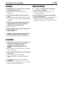
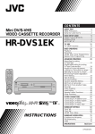
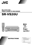
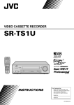
Mini DV/S-VHS
VIDEO CASSETTE RECORDER
VCR TV CABLE/DBS A.MONITOR POWER
A/B
PROG
CHECK
TV/VCR
DISPLAY
ENTER/OSD
T
W
1
2
3
2
4
5
6
DBS
DAILY(M-F)
WEEKLY
7
8
9
C. RESET
AUX
0
CANCEL
START
STOP
4
TIMER
DATE
CH
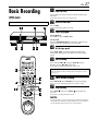
EXPRESS PROGRAMMING
1
SP/LP
SP/EP
PROG
DV
S-VHS
PLAY
FF
REW
STOP
REC
PAUS
E
TV CH +
TV
VOL
Ð
TV
VOL
+
POWER
ME N
U
3
EJECT
EJECT
TV CH Ð
OK
ST A R T
R.A. E
IN/OUTJOG/
DI T
SHUTTLE
PULL-OPEN
STOP
PLAY
REW
PAUSE
CH – / +
PUSH / TURN
DV
DV
DUB S-VHS
REC
FF
PULL-OPEN
S-VHS
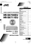
24HR
QUICK
PROGRAM
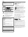
For Customer Use:
Enter below the Model No. and
Serial No. which are located on the
rear of cabinet. Retain this
information for future reference.
Model No.
Serial No.
LPT0641-001A
2 EN
Dear Customer,
Thank you for purchasing the JVC Mini DV/S-VHS video
cassette recorder. Before use, please read the safety
information and precautions to ensure safe use of your new
VCR.
CAUTIONS
The lightning flash with arrowhead symbol, within
an equilateral triangle, is intended to alert the user
to the presence of uninsulated “dangerous voltage”
within the product’s enclosure that may be of
sufficient magnitude to constitute a risk of electric
shock to persons.
The exclamation point within an equilateral
triangle is intended to alert the user to the presence
of important operating and maintenance
(servicing) instructions in the literature
accompanying the appliance.
WARNING:
TO PREVENT FIRE OR SHOCK HAZARD, DO
NOT EXPOSE THIS UNIT TO RAIN OR
MOISTURE.
CAUTION:
This video cassette recorder should be used with AC 120Vd,
60Hz only.
To prevent electric shocks and fire hazards, DO NOT use any
other power source.
CAUTION:
TO PREVENT ELECTRIC SHOCK, MATCH WIDE BLADE OF
PLUG TO WIDE SLOT, FULLY INSERT.
ATTENTION:
POUR ÉVITER LES CHOCS ÉLECTRIQUES, INTRODUIRE LA
LAME LA PLUS LARGE DE LA FICHE DANS LA BORNE
CORRESPONDANTE DE LA PRISE ET POUSSER JUSQU’AU
FOND.
Note to CATV system installer:
This reminder is provided to call the CATV system installer’s
attention to Article 820-40 of the NEC that provides guidelines
for proper grounding and, in particular, specifies that the cable
ground shall be connected to the grounding system of the
building, as close to the point of cable entry as practical.
CAUTION:
Changes or modifications not approved by JVC could void
user’s authority to operate the equipment.
Failure to heed the following precautions may result in damage
to the VCR, Remote or video cassette.
1. DO NOT place the VCR . . .
...in an environment prone to extreme temperatures or
humidity.
...in direct sunlight.
...in a dusty environment.
...in an environment where strong magnetic fields are
generated.
...on a surface that is unstable or subject to vibration.
2. DO NOT block the VCR’s ventilation openings.
3. DO NOT place heavy objects on the VCR or on the Remote.
4. DO NOT place anything which might spill on the top of the
VCR or on the Remote.
5. AVOID violent shocks to the VCR during transport.
MOISTURE CONDENSATION
Moisture in the air will condense on the VCR when you move it
from a cold place to a warm place, or under extremely humid
conditions—just as water droplets form on the surface of a glass
filled with cold liquid. Moisture condensation on the head drum
will cause damage to the tape. In conditions where
condensation may occur, keep the VCR’s power turned on for a
few hours to let the moisture dry before inserting a tape.
3
VCR Plus+, C and PlusCode are registered trademarks of
Gemstar Development Corporation.
The VCR Plus+ system is manufactured under license from
Gemstar Development Corporation.
DSSTM is an official trademark of DIRECTV, Inc., a unit of GM
Hughes Electronics. PRIMESTAR is a registered service mark of
Primestar Partners, L.P. DISH NetworkTM is a trademark of
Echostar Communications Corporation.
● Cassettes marked “S-VHS” and “VHS” can be used with this
video cassette recorder. However, S-VHS recordings are
possible only with cassettes marked “S-VHS”.
By using the S-VHS ET function, it is possible to record and
play back with S-VHS picture quality on VHS cassettes with
this VCR.
● Cassettes marked “Mini DV” can be used with the DV deck of
this VCR. The DV deck can play back and record only NTSC
signals.
This product incorporates copyright protection technology that is
protected by method claimes of certain U.S. patents and other
intellectual property rights owned by Macrovision Corporation
and other rights owners. Use of this copyright protection
technology must be authorized by Macrovision Corporation, and
is intended for home and other limited viewing users only unless
otherwise authorized by Macrovision Corporation. Reverse
engineering or disassembly is prohibited.
EN
IMPORTANT PRODUCT SAFETY
INSTRUCTIONS
Electrical energy can perform many useful functions. But
improper use can result in potential electrical shock or fire
hazards. This product has been engineered and manufactured to
assure your personal safety. In order not to defeat the built-in
safeguards, observe the following basic rules for its installation,
use and servicing.
ATTENTION:
Follow and obey all warnings and instructions marked on your
product and its operating instructions. For your safety, please
read all the safety and operating instructions before you operate
this product and keep this booklet for future reference.
INSTALLATION
1. Grounding or Polarization
(A) Your product may be equipped with a polarized alternatingcurrent line plug (a plug having one blade wider than the
other). This plug will fit into the power outlet only one way.
This is a safety feature.
If you are unable to insert the plug fully into the outlet, try
reversing the plug. If the plug should still fail to fit, contact
your electrician to replace your obsolete outlet. Do not
defeat the safety purpose of the polarized plug.
(B) Your product may be equipped with a 3-wire grounding-type
plug, a plug having a third (grounding) pin. This plug will
only fit into a grounding-type power outlet. This is a safety
feature.
If you are unable to insert the plug into the outlet, contact
your electrician to replace your obsolete outlet. Do not
defeat the safety purpose of the grounding-type plug.
2. Power Sources
Operate your product only from the type of power source
indicated on the marking label. If you are not sure of the type of
power supply to your home, consult your product dealer or local
power company. If your product is intended to operate from
battery power, or other sources, refer to the operating
instructions.
3. Overloading
Do not overload wall outlets, extension cords, or integral
convenience receptacles as this can result in a risk of fire or
electric shock.
4. Power Cord Protection
Power supply cords should be routed so that they are not likely
to be walked on or pinched by items placed upon or against
them, paying particular attention to cords at plugs, convenience
receptacles, and the point where they exit from the product.
3
5. Ventilation
Slots and openings in the cabinet are provided for ventilation. To
ensure reliable operation of the product and to protect it from
overheating, these openings must not be blocked or covered.
● Do not block the openings by placing the product on a bed,
sofa, rug or other similar surface.
● Do not place the product in a built-in installation such as a
bookcase or rack unless proper ventilation is provided or the
manufacturer’s instructions have been adhered to.
6. Wall or Ceiling Mounting
The product should be mounted to a wall or ceiling only as
recommended by the manufacturer.
ANTENNA INSTALLATION INSTRUCTIONS
1. Outdoor Antenna Grounding
If an outside antenna or cable system is connected to the
product, be sure the antenna or cable system is grounded so as
to provide some protection against voltage surges and built-up
static charges. Article 810 of the National Electrical Code, ANSI/
NFPA 70, provides information with regard to proper grounding
of the mast and supporting structure, grounding of the lead-in
wire to an antenna discharge unit, size of grounding connectors,
location of antenna discharge unit, connection to grounding
electrodes, and requirements for the grounding electrode.
2. Lightning
For added protection for this product during a lightning storm, or
when it is left unattended and unused for long periods of time,
unplug it from the wall outlet and disconnect the antenna or
cable system. This will prevent damage to the product due to
lightning and power-line surges.
3. Power Lines
An outside antenna system should not be located in the vicinity
of overhead power lines or other electric light or power circuits,
or where it can fall into such power lines or circuits. When
installing an outside antenna system, extreme care should be
taken to keep from touching such power lines or circuits as
contact with them might be fatal.
4 EN
USE
SERVICING
1. Accessories
To avoid personal injury:
● Do not place this product on an unstable cart, stand, tripod,
bracket, or table. It may fall, causing serious injury to a child
or adult, and serious damage to the product.
● Use only with a cart, stand, tripod, bracket, or table
recommended by the manufacturer or sold with the product.
● Use a mounting accessory recommended by the manufacturer
and follow the manufacturer’s instructions for any mounting of
the product.
● Do not try to roll a cart with small casters across thresholds or
deep-pile carpets.
1. Servicing
If your product is not operating correctly or exhibits a marked
change in performance and you are unable to restore normal
operation by following the detailed procedure in its operating
instructions, do not attempt to service it yourself as opening or
removing covers may expose you to dangerous voltage or other
hazards. Refer all servicing to qualified service personnel.
2. Product and Cart Combination
A product and cart combination should
be moved with care. Quick stops,
excessive force, and uneven surfaces
may cause the product and cart
combination to overturn.
3. Water and Moisture
Do not use this product near water—for example, near a bath
tub, wash bowl, kitchen sink or laundry tub, in a wet basement,
or near a swimming pool and the like.
4. Object and Liquid Entry
Never push objects of any kind into this product through
openings as they may touch dangerous voltage points or shortout parts that could result in a fire or electric shock. Never spill
liquid of any kind on the product.
5. Attachments
Do not use attachments not recommended by the manufacturer
of this product as they may cause hazards.
6. Cleaning
Unplug this product from the wall outlet before cleaning. Do not
use liquid cleaners or aerosol cleaners. Use a damp cloth for
cleaning.
7. Heat
The product should be situated away from heat sources such as
radiators, heat registers, stoves, or other products (including
amplifiers) that produce heat.
2. Damage Requiring Service
Unplug this product from the wall outlet and refer servicing to
qualified service personnel under the following conditions:
a. When the power supply cord or plug is damaged.
b. If liquid has been spilled, or objects have fallen into the
product.
c. If the product has been exposed to rain or water.
d. If the product does not operate normally by following the
operating instructions. Adjust only those controls that are
covered by the operating instructions as an improper
adjustment of other controls may result in damage and will
often require extensive work by a qualified technician to
restore the product to its normal operation.
e. If the product has been dropped or damaged in any way.
f. When the product exhibits a distinct change in
performance—this indicates a need for service.
3. Replacement Parts
When replacement parts are required, be sure the service
technician has used replacement parts specified by the
manufacturer or which have the same characteristics as the
original part. Unauthorized substitutions may result in fire,
electric shock or other hazards.
4. Safety Check
Upon completion of any service or repairs to this product, ask
the service technician to perform safety checks to determine that
the product is in safe operating condition.
HOW TO USE THIS INSTRUCTION MANUAL
● All major sections and subsections are listed in the Table Of
Contents on page 5. Use this when searching for information
on a specific procedure or feature.
● The Index on pages 6 – 11 lists frequently-used terms, and the
number of the page on which they are used or explained in the
manual. This section also illustrates the controls and
connections on the front and rear panel, the front display
panel and the remote control.
● The 墌 mark signals a reference to another page for
instructions or related information.
● Operation buttons necessary for the various procedures are
clearly indicated through the use of illustrations at the
beginning of each major section.
BEFORE YOU INSTALL YOUR NEW VCR . . .
. . . please read the sections/literature listed below.
● “CAUTIONS” on page 2
● “IMPORTANT PRODUCT SAFETY INSTRUCTIONS” on
pages 3 – 4
EN
CONTENTS
INDEX
6
FRONT VIEW ..........................................................................6
REAR VIEW .............................................................................7
FRONT DISPLAY PANEL .........................................................8
REMOTE ..................................................................................9
How To Use ............................................................................9
ON-SCREEN DISPLAY (for VHS deck) ...................................10
ON-SCREEN DISPLAY (for DV deck) .....................................11
INSTALLING YOUR NEW VCR
12
Basic Connections ..................................................... 12
S-VIDEO Connection ................................................. 13
INITIAL SETTINGS
14
Plug & Play Set .......................................................... 14
Language ................................................................... 15
Clock Set ................................................................... 16
Preparations ...........................................................................16
Semiauto Clock Set ................................................................17
Manual Clock Set ..................................................................17
Tuner Set ................................................................... 18
Auto Channel Set ...................................................................18
Manual Channel Set ..............................................................19
Cable Box Control Setting ......................................... 20
Installing Controller ...............................................................20
Setting cable box's brand and channel ...................................21
DBS Receiver Control Setting .................................... 23
Installing Controller ...............................................................23
Setting DBS receiver's brand and channel ..............................24
PLAYBACK/RECORDING ON VHS DECK
26
Basic Playback ........................................................... 26
Basic Recording ......................................................... 27
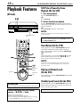
Playback Features ...................................................... 28
Still Picture/Frame-By-Frame Playback (On the VCR) .............28
Slow Motion (On the VCR) ....................................................28
High-Speed (Turbo) Search (On the VCR) ..............................28
Variable Speed Search (On the VCR) .....................................28
Still Picture/Frame-By-Frame Playback (On the Remote) ........29
Slow Motion (On the Remote) ...............................................29
High-Speed (Turbo) Search (On the Remote) .........................29
Variable Speed Search (On the Remote) ................................29
Repeat Playback ....................................................................30
Index Search ..........................................................................30
Next Function Memory ..........................................................30
Manual Tracking ....................................................................31
Soundtrack Selection .............................................................31
Recording Features .................................................... 32
Record One Program While Watching Another .....................32
Instant Timer Recording (ITR) .................................................32
Elapsed Recording Time Indication ........................................33
Tape Remaining Time ............................................................33
Retake ...................................................................................34
Second Audio Recording .......................................................34
Active Video Calibration ........................................... 35
Playback ................................................................................35
Recording ..............................................................................35
PLAYBACK/RECORDING ON DV DECK
5
36
Basic Playback ............................................................36
Basic Recording ..........................................................37
Playback Features .......................................................38
Still Picture/Frame-By-Frame Playback (On the VCR) .............38
Slow Motion (On the VCR) .................................................... 38
High-Speed (Turbo) Search (On the VCR) .............................. 38
Variable Speed Search (On the VCR) .....................................38
Still Picture/Frame-By-Frame Playback (On the Remote) ........39
Slow Motion (On the Remote) ...............................................39
High-Speed (Turbo) Search (On the Remote) .........................39
Variable Speed Search (On the Remote) ................................39
Next Function Memory ..........................................................40
Soundtrack Selection .............................................................40
Recording Features .....................................................41
Second Audio Recording .......................................................41
Record One Program While Watching Another .....................41
Instant Timer Recording (ITR) ................................................41
Time Code .............................................................................41
TIMER RECORDING
42
VCR Plus+ Timer Programing ....................................42
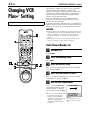
Changing VCR Plus+ Setting ......................................44
®
®
Guide Channel Number Set ................................................... 44
Guide Channel Number ........................................................45
Express Timer Programing ..........................................46
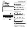
24HR Quick Programing ............................................48
Check, cancel and change programs .....................................50
To cancel or change a program... ..........................................50
When programs overlap each other .......................................51
EDITING
52
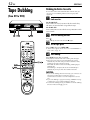
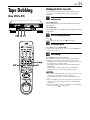
Tape Dubbing (from DV to VHS) ...............................52
Dubbing An Entire Cassette ................................................... 52
Tape Dubbing (from VHS to DV) ................................53
Dubbing An Entire Cassette ................................................... 53
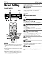
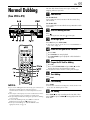
Normal Dubbing (from DV to VHS) ...........................54
Normal Dubbing (from VHS to DV) ...........................55
Edit From A Camcorder ..............................................56
Edit To Or From Another VCR/PC ..............................58
Audio Dubbing ...........................................................60
VHS Audio Dubbing ..............................................................60
DV Audio Dubbing ...............................................................60
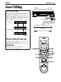
Insert Editing ..............................................................62
VHS Insert Editing ..................................................................62
DV Insert Editing (SP mode only) ...........................................62
AV Insert Editing (VHS deck only) ..........................................63
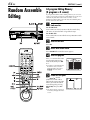
Random Assemble Editing ..........................................64
64-program Editing Memory (8 programs x 8 scenes) ............64
REMOTE CONTROL FUNCTIONS
66
Remote A/B Code Switching ..................................................66
TV Multi-Brand Remote Control ............................................67
Cable Box Multi-Brand Remote Control .................................68
DBS Receiver Multi-Brand Remote Control ...........................69
SUBSIDIARY SETTINGS
70
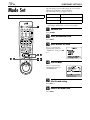
Mode Set ....................................................................70
TROUBLESHOOTING
77
QUESTIONS AND ANSWERS
81
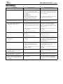
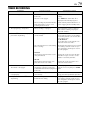
PLAYBACK ............................................................................81
RECORDING ......................................................................... 81
TIMER RECORDING .............................................................81
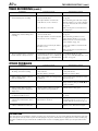
SPECIFICATIONS
82
INDEX
83
FOR SERVICING (Only in U.S.A.)
84
WARRANTY (Only in U.S.A.)
85
6 EN
INDEX
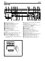
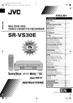
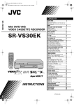
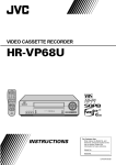
FRONT VIEW
POWER
EJECT
EJECT
REW
STOP
PLAY
PAUSE
CH – / +
PUSH / TURN
DV
DV IN/OUT
DV
DUB S-VHS
REC
S-VHS
24HR.
QUICK
PROGRAM
FF
R.A.EDIT
INSERT
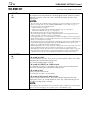
A POWER Button 墌 pg. 15
B DV Eject (EJECT ) Button 墌 pg. 36, 37
C STOP 8 Button 墌 pg. 26, 27, 36, 37
D Mini DV Cassette Loading Slot
E PLAY 4 Button 墌 pg. 26, 36
F PAUSE 9 Button 墌 pg. 27, 28, 37, 38
G DV Button 墌 pg. 36, 37
H S-VHS Button 墌 pg. 26, 27
I VHS Cassette Loading Slot
J Random Assemble Edit (R.A.EDIT) Button
墌 pg. 64
K Random Assemble Edit START Button 墌 pg. 65
L VIDEO Input Connector 墌 pg. 56, 62
M VHS Eject (EJECT ) Button 墌 pg. 26, 27
N DV IN/OUT connector (i.Link*) 墌 pg. 56
* i.Link refers to the IEEE1394-1995 industry specification and
extensions thereof. The logo is used for products compliant with
the i.Link standard.
PULL-OPEN
To access covered buttons/connectors, pull and open the
cover.
START
IN /OUT
A.DUB
O Dubbing Direction (DV / S-VHS) Indicators
墌 pg. 52, 53
P Dubbing (DUB) Button 墌 pg. 52, 53
Dubbing Direction ( / ) Buttons 墌 pg. 52, 53
Q REC 7 Button 墌 pg. 27, 37
R DV mode Indicators 墌 pg. 36, 37
S Remote Sensor
T Front Display Panel 墌 pg. 8
U VHS mode Indicators 墌 pg. 26, 27
V 24HR QUICK PROGRAM Button 墌 pg. 48
W ADVANCED JOG Dial 墌 pg. 26, 36, 48
X INSERT Button 墌 pg. 63
Y Random Assemble Edit IN/OUT Button 墌 pg. 64
Z Audio Dubbing (A.DUB) Button 墌 pg. 61
a Remote PAUSE Connector 墌 pg. 56
b AUDIO Input Connectors 墌 pg. 56, 60, 62
c S-VIDEO Input Connector 墌 pg. 56, 62
EN
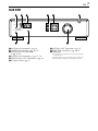
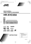
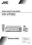
REAR VIEW
S VIDEO VIDEO
ANTENNA IN
IN
L-1
AUDIO
R
L
S VIDEO VIDEO
AUDIO
R
L
VHF/UHF
ANTENNA OUT
CABLE
BOX
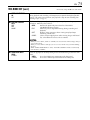
A ANTENNA IN Connector 墌 pg. 12
B S VIDEO IN Connector 墌 pg. 56, 58
C VIDEO/AUDIO IN Connectors
墌 pg. 56, 58
D S VIDEO OUT Connectors 墌 pg. 13, 58
E VIDEO/AUDIO OUT Connectors 墌 pg. 58
F AC Power Cord 墌 pg. 12
G ANTENNA OUT Connector 墌 pg. 12
H CABLE BOX Connector 墌 pg. 20, 23
I Cooling fan
● This prevents the temperature from rising inside the VCR.
Do not remove it.
● Install the VCR so as not to block the area around the fan.
● The fan may be activated even if the VCR is turned off.
7
8 EN
INDEX (cont.)
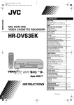
FRONT DISPLAY PANEL
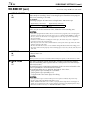
A Symbolic Mode Indicators
PLAY:
FF/REW VARIABLE
SEARCH:
STILL:
SLOW:
RECORD:
RECORD PAUSE:
AUDIO DUBBING:
AUDIO DUBBING PAUSE:
INSERT:
INSERT PAUSE:
AV INSERT:
AV INSERT PAUSE:
B Tape Speed Indicators 墌 pg. 27, 37
C Start Time Indicator ( ) 墌 pg. 48
Stop Time Indicator ( ) 墌 pg. 48
D “Timer” Indicator 墌 pg. 43, 47, 48
E Tape Remaining Time Indicator (VHS deck only)
墌 pg. 33
F S-VHS Indicator (VHS deck only) 墌 pg. 72
G “Cassette Loaded” Mark
H Counter/Remain Display (VHS deck only)
墌 pg. 33
Time Code Display (DV deck only) 墌 pg. 41
Channel/Mode Display (L-1 or F-1) 墌 pg. 14
Clock Display 墌 pg. 14
EN
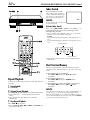
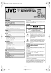
REMOTE
VCR TV CABLE/DBS A.MONITOR POWER
A/B
PROG
CHECK
TV/VCR
DISPLAY
ENTER/OSD
T
W
1
2
3
4
5
6
DBS
DAILY(M-F)
WEEKLY
7
8
9
C. RESET
AUX
CANCEL
0
2
START
STOP
4
TIMER
DATE
CH
EXPRESS PROGRAMMING
1
SP/LP
SP/EP
PROG
DV
S-VHS
PLAY
REW
STOP
REC
FF
PAUS
E
TV CH +
TV
VOL
–
TV
VOL
+
M EN
U
3
TV CH –
OK
ST A R T
R.A . E
IN/OUTJOG/
DI T
SHUTTLE
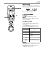
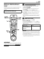
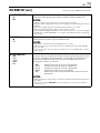
Buttons with a small dot on the left side of the name can also
be used to operate your TV with the VCR/TV/CABLE/DBS
switch set to TV. (墌 pg. 67)
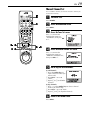
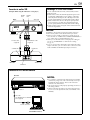
How To Use
Before use, insert two AA size batteries into the Remote with
the polarity ( and ) matched correctly as indicated on
the battery compartment or on the lid.
The Remote can operate most of your VCR’s functions, as
well as basic functions of TV sets, cable boxes and DBS
receivers.
● Point the Remote toward the remote sensor on the target
component.
● The maximum operating distance of the remote control is
about 8 m.
NOTE:
If the Remote does not work properly, remove its batteries,
wait for a few seconds, replace the batteries and then try
again.
9
A VCR/TV/CABLE/DBS Button 墌 pg. 67, 68, 69
B TV/VCR Button 墌 pg. 67
C A/B Code Button 墌 pg. 66
D Number Keys 墌 pg. 27, 37
E DBS Button 墌 pg. 47
F CANCEL Button 墌 pg. 50
Counter Reset (C.RESET) Button 墌 pg. 33
G STOP +/– Button 墌 pg. 46
H START +/– Button 墌 pg. 46
I PROG Button 墌 pg. 46
J Auto Tracking p Button 墌 pg. 31
SP/LP, SP/EP Button 墌 pg. 27, 37
K Rewind (REW 3) Button 墌 pg. 26, 36
L REC 7 Button 墌 pg. 27, 37
M STOP 8 Button 墌 pg. 26, 36
N r t Button 墌 pg. 15
TV CH +/– Button 墌 pg. 67
O MENU Button 墌 pg. 15
P OK Button 墌 pg. 15
Random Assemble Edit START Button 墌 pg. 65
Q JOG dial 墌 pg. 26, 36
R A. MONITOR Button 墌 pg. 31, 40
^ (TV Muting) Button 墌 pg. 67
S POWER Button 墌 pg. 15
T DISPLAY Button 墌 pg. 33
ENTER Button 墌 pg. 67
On-Screen Display (OSD) Button 墌 pg. 10, 11
U PROG CHECK Button 墌 pg. 50
V DAILY (M–F) Button 墌 pg. 43, 47
W WEEKLY Button 墌 pg. 43, 47
X TIMER Button 墌 pg. 43, 47
Y AUX Button 墌 pg. 56
Z DATE +/– Button 墌 pg. 47
a CH +/– Button 墌 pg. 27, 37
b S-VHS Button 墌 pg. 26, 27
c DV Button 墌 pg. 36, 37
d Fast Forward (FF 5) Button 墌 pg. 26, 36
e PLAY 4 Button 墌 pg. 26, 36
f PAUSE 9 Button 墌 pg. 27, 37
g w e Button 墌 pg. 29, 39
TV Volume (VOL) +/– Button 墌 pg. 67
h Random Assemble Edit (R.A.EDIT) Button
墌 pg. 64
i Random Assemble Edit IN/OUT Button 墌 pg. 64
j JOG/SHUTTLE Button 墌 pg. 29, 39
k SHUTTLE Ring 墌 pg. 29, 39
10 EN
INDEX (cont.)
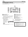
ON-SCREEN DISPLAY (for VHS deck)
If you press DISPLAY/OSD on the Remote when “SUPERIMPOSE” is set to “ON” (墌 pg. 71), various operational
indicators appear on the TV screen.
A Operation Mode Indicators
B Tape Speed SP/EP
C Timer Warning Display
A warning appears on the TV screen to tell you that the timerrecording is to start in 5 minutes if you’re not in the Timer
mode at that time. The warning blinks for the entire 5
minutes leading up to the start of timer recording. To clear
the display, press CANCEL on the Remote.
D Tape Position Indicator
The tape position indicator
appears on the TV screen
when you press REW (3)
or FF (5) from the Stop
mode or perform an Index
Search (墌 pg. 30). The
position of “q” in relation to
“B” (beginning) or “E” (end)
shows you where you are
Beginning
on the tape.
End
NOTE:
Depending on the type of tape being used, the tape position
indicator may not appear correctly.
E Index number 墌 pg. 30
F Tape Remaining Time Indicator
G Counter Display 墌 pg. 33
H Audio Mode Display 墌 pg. 31
I VHS Indicator
J SAP Indicator 墌 pg. 34
K Stereo program Indicator 墌 pg. 34
L Day/Clock Display
M Channel Position Number/
Auxiliary Input Indicator (L-1 or F-1)
Dubbing Direction Indicators
(DV ] VHS) 墌 pg. 52
N “Cassette Loaded” Mark
To recall an indication
A Press DISPLAY/OSD.
●All indications corresponding to the current status are
displayed for 5 seconds. After that, the counter
information and RECORD/PAUSE if in the Record Pause
mode, remain on the screen.
B Press DISPLAY/OSD again to clear the display.
●The RECORD/PAUSE indication remains on the screen.
EN
11
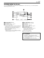
ON-SCREEN DISPLAY (for DV deck)
If you press DISPLAY/OSD on the Remote when “SUPERIMPOSE” is set to “ON” (墌 pg. 71), various operational
indicators appear on the TV screen.
A Operation Mode Indicators
B Tape Speed SP/LP
C Sound Mode Display 墌 pg. 76
D Timer Warning Display
A warning appears on the TV screen to tell you that the timerrecording is to start in 5 minutes if you’re not in the Timer
mode at that time. The warning blinks for the entire 5
minutes leading up to the start of timer recording. To clear
the display, press CANCEL on the Remote.
ERROR Indicator*
* ERROR indicator appears when you start dubbing a tape with a
copy protection signals or when Audio Dubbing or Insert Editing is
not possible depending on the condition.
E Time Code Display 墌 pg. 41
F Audio Mode Display 墌 pg. 40
G DV Indicator
H SAP Indicator 墌 pg. 41
I Stereo program Indicator 墌 pg. 41
J Day/Clock Display
K Channel Position Number/
Auxiliary Input Indicator (L-1 or F-1)
Dubbing Direction Indicators
(VHS ] DV) 墌 pg. 53
L “Cassette Loaded” Mark
To recall an indication
A Press DISPLAY/OSD.
●All indications corresponding to the current status are
displayed for 5 seconds. After that, the counter
information and RECORD/PAUSE if in the Record Pause
mode, remain on the screen.
B Press DISPLAY/OSD again to clear the display.
●The RECORD/PAUSE indication remains on the screen.
12 EN
INSTALLING YOUR NEW VCR
Basic Connections
Antenna or Cable
A Check the contents.
B Situate the VCR.
Flat Feeder
Place the VCR on a stable, horizontal surface.
Matching Transformer
(not supplied)
AC Outlet
ANTENNA
IN
THESE STEPS MUST BE COMPLETED BEFORE ANY
VIDEO OPERATION CAN BE PERFORMED.
Make sure the package contains all of the accessories
listed in “SPECIFICATIONS” on page 82.
Coaxial Cable
VIDEO
OUT
It’s essential that your VCR be properly connected.
AUDIO
OUT
AC
Power
Cord
Back of VCR
ANTENNA
OUT
C Connect the VCR to TV.
A Disconnect the TV antenna from the TV.
B Connect the TV antenna cable to the ANTENNA IN
connector on the rear panel of the VCR.
C Connect the supplied RF cable between the
ANTENNA OUT connector on the rear panel of the
VCR and the TV’s antenna terminal.
D Connect the supplied Audio/Video cable between the
AUDIO/VIDEO OUT connectors on the rear of the
VCR and the Audio/Video input connectors on the TV.
● Set your TV to AV mode.
● For switching the TV’s mode, refer to the instruction manual of
your television.
● To obtain high-quality S-VHS pictures, you can also use the
S-VIDEO connection described on page 13.
D Connect the VCR to power source.
Audio/Video Cable
(supplied)
Plug the end of the AC power cord into an AC outlet.
● The clock and tuner channels will automatically be set when
the antenna is connected and when the AC power cord is first
connected to an AC outlet (墌 pg. 14). (If “Auto” or “CH” is
displayed on the front display panel before the VCR is
powered on, the clock and tuner channels are being set
automatically. Wait for the time to be displayed on the front
display panel before turning on the VCR.)
To Audio/Video
Input Connectors
RF Cable
(supplied)
To 75 ohm Terminal
TV
EN
13
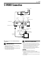
S-VIDEO Connection
Antenna or Cable
Coaxial Cable
Flat Feeder
Matching Transformer
(not supplied)
AC Outlet
AUDIO
OUT
S VIDEO
OUT
AC Power Cord
ANTENNA IN
ANTENNA OUT
Back of VCR
S-Video
Cable
(supplied)
RF Cable
(supplied)
Audio/Video Cable
(supplied)
Yellow:
Not connected
To Audio/Video
Input Connectors
To S-VIDEO Input
Connector
To 75 ohm Terminal
TV
8 To connect to a TV with S-VIDEO/AUDIO input
connectors . . .
A
Connect the VCR to TV.
A Connect the antenna, VCR and TV as per “Basic
Connections” (墌 pg. 12).
B Connect the VCR’s S VIDEO OUT connector to the
TV’s S-VIDEO input connector.
C Connect the VCR’s AUDIO OUT connectors to the
TV’s AUDIO input connectors.
B Connect the VCR to power source.
Plug the end of the AC power cord into an AC outlet.
● The clock and tuner channels will automatically be set when
the antenna is connected and when the AC power cord is first
connected to an AC outlet (墌 pg. 14). (If “Auto” or “CH” is
displayed on the front display panel before the VCR is
powered on, the clock and tuner channels are being set
automatically. Wait for the time to be displayed on the front
display panel before powering on the VCR.)
NOTES:
● You can obtain high-quality S-VHS pictures.
● To operate the VCR with your TV using the S-VIDEO
connection, set your TV to its AV mode. You can also use the
TV/VCR button on the VCR's Remote to set your TV to the AV
mode. (墌 pg. 67)
● For switching the TV’s mode, refer to the instruction manual of
your television.
14 EN
INITIAL SETTINGS
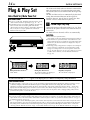
Plug & Play Set
Auto Clock Set/Auto Tuner Set
ATTENTION:
● If you use a cable box, Plug&Play will not function; set the
clock and tuner channels separately. (墌 pg. 16 – 19)
● Depending on areas or reception conditions, the VCR may
not receive the Auto clock setting data from the PBS
channel. If this function is taking a considerable amount of
time, it may be necessary to perform the Semiauto or
Manual Clock Set procedure.
This VCR sets the clock and tuner channels automatically
when AC power cord is first connected to an AC outlet.
The antenna cable must be connected for the Plug & Play
setting.
The time and date can be set automatically by the clock
setting data transmitted from one of the regular TV
broadcast channels. We call this TV channel the “host
channel” and it is a PBS channel in your area.
A Perform Plug & Play setup.
Connect the antenna cable to the VCR (墌 pg. 12). Then
connect the AC power cord to an AC outlet. Do not turn
on the VCR.
The clock and tuner channels will be set automatically.
NOTES:
1
3
During Initial Auto Clock Set
“Auto” blinks.
2
● Auto Clock Set is performed first.
“Auto” blinks on the front display panel during Auto Clock Set.
● Auto Channel Set is performed next. Auto Channel Set scans
all the channels that are receivable by your VCR. During Auto
Channel Set, the channel numbers are displayed as they are
scanned and set.
● When Plug & Play setting has been complete successfully, the
correct clock time is displayed. If you perform Plug & Play
setting successfully, there is no need to perform “Clock Set”
(墌 pg. 16) and “Tuner Set” (墌 pg. 18). If, however, you want
to add or delete channels, refer to “Manual Channel Set”
(墌 pg. 19).
During Auto Channel Set
The channel numbers are displayed
as they are scanned and set.
Plug&Play Completed
The current time is displayed.
* If an incorrect clock time or “– –:– –” appears on the display panel, see “What to do if Plug & Play setting failed” below.
INFORMATION
● If “AUTO CLOCK” is set to “ON” (墌 pg. 17), the clock will be adjusted automatically by the host channel every hour (except
11:00 PM, midnight, 1:00 AM and 2:00 AM) using the incoming PBS channel clock setting data. (This automatic clock
adjustment can only be performed when the VCR is turned off. The clock will be adjusted just on these hours — on the time
displayed on the front display panel, not on the actual real time.) The default setting of “AUTO CLOCK” is “ON”. (墌 pg. 17)
● If the memory backup fails, because a power outage occurs or because the AC power cord is unplugged, Plug & Play will be
performed when power is restored to the VCR.
What to do if Plug & Play setting failed
● If an incorrect time is displayed on the front display panel, you may be receiving the clock setting data of a PBS channel from an
adjacent time zone, or an incorrect PBS channel from a cable TV system. In this case, perform “Semiauto Clock Set” (墌 pg. 17)
or “Manual Clock Set” (墌 pg. 17).
● If “– –:– –” appears on the front display panel, your antenna cable may not be connected to the VCR or there may not be a Host
PBS signal available in your area. Ensure that the antenna cable is connected correctly. Then turn on and off the VCR; the Plug &
Play setting will be automatically reactivated. If Plug & Play setting is not performed though the antenna cable is connected
correctly, perform “Manual Clock Set” (墌 pg. 17) and “Auto Channel Set” (墌 pg. 18) or “Manual Channel Set” (墌 pg. 19).
EN
This VCR offers you the language choice to view menus
and some messages — in English, Spanish or French. The
default setting is “ENGLISH”.
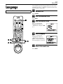
Language
Turn on the TV and select the AV mode.
A Turn on the VCR.
Press POWER.
B Access the Main Menu screen.
Press MENU.
T
C Access the Initial Set screen.
W
1
2
3
4
5
6
7
8
9
2
0
1
15
Press rt to move the
highlight bar (arrow) to
“INITIAL SET”, then press OK
or e.
4
DV
S-VHS
D Select the language.
Press rt to move the
highlight bar (arrow) to
“LANGUAGE”, then press
OK or e repeatedly until the
desired language is selected.
3
E Return to the normal screen.
Press MENU.
16 EN
INITIAL SETTINGS (cont.)
Perform clock setting only if the clock has not been set
correctly by the Plug&Play setting or if you use a cable
box.
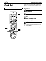
Clock Set
Turn on the TV and select the AV mode.
Preparations
A Turn on the VCR.
Press POWER.
T
B Access the Main Menu screen.
Press MENU.
W
1
2
3
2
4
5
6
7
8
9
0
1
4
DV
S-VHS
C Access the Initial Set screen.
Press rt to move the highlight bar (arrow) to “INITIAL
SET”, then press OK or e.
D Access the Clock Set screen.
Press rt to move the highlight bar (arrow) to “CLOCK
SET”, then press OK or e.
● “CABLE BOX USERS SET CLOCK MANUALLY” appears on the
screen for about 5 seconds, then the Clock Set screen appears.
3
EN
Semiauto Clock Set
You can change the host channel/D.S.T. (Daylight Saving Time)/
time zone setting manually. First follow steps 1 to 4 in
“Preparations” (墌 pg. 16), then go to the following steps.
NOTE:
The time set previously will be erased when “AUTO CLOCK”,
“HOST CH”, “D.S.T.” or “TIME ZONE” setting is changed.
A Set “Auto Clock” to “ON”.
Press OK or e repeatedly to
move the highlight bar to
“AUTO CLOCK”, then press
rt so that “ON” is selected.
B Select the host channel.
You can either select “AUTO” or enter a PBS channel
number.
Press OK or e to move the highlight bar to “HOST CH”,
then press rt repeatedly until “AUTO” or the desired
PBS channel number is selected.
NOTE:
Some PBS channels do not transmit clock setting data.
C Select the D.S.T. mode.
Press OK or e to move the highlight bar to “D.S.T.”, then
press rt repeatedly until the desired setting is selected.
AUTO: Select if you want to adjust your VCR’s clock
automatically by the incoming signal from the
host channel. Be sure to select the correct time
zone manually in step 4.
ON:
Adjustment will be made by the built-in clock
itself.
OFF: Select when Daylight Saving Time does not apply
to you.
D Select the time zone.
Press OK or e to move the highlight bar to “TIME
ZONE”, then press rt repeatedly until “AUTO” or the
desired time zone is selected. Each time you press the
button, the time zone changes as follows:
{ AUTO { ATLANTIC { EASTERN { CENTRAL
{ MOUNTAIN { PACIFIC { ALASKA { HAWAII
{ (back to the beginning)
NOTE:
If an incorrect time is displayed by the Plug & Play function, you
may be receiving the clock setting data of a PBS channel from an
adjacent time zone or from an incorrect PBS channel from a
cable TV system. If you selected “AUTO” for the host channel in
step 2, be sure to select the correct time zone manually.
17
E Complete the Semiauto Clock Set.
Press MENU to return to normal screen.
IMPORTANT
Turn off the VCR after performing Semiauto Clock. “Auto”
will appear on the display panel while the clock is being set.
The current clock time will appear automatically when the
clock setting is complete.
AUTO DAYLIGHT SAVING TIME
This function enables automatic adjustment of the VCR’s
clock at the start and end of Daylight Saving Time.
With Auto DST activated, . . .
. . . on the first Sunday of April at 2:00 AM, the clock is
adjusted to 3:00 AM.
. . . on the last Sunday of October at 2:00 AM, the clock is
adjusted to 1:00 AM.
Manual Clock Set
First follow steps 1 to 4 in “Preparations” (墌 pg. 16), then go to
the following steps.
A Set time, date and year.
Press rt until the desired
time appears, then press OK
or e. Set the date and year in
the same way.
● Holding rt changes the time
in 30-minute intervals, or
changes the date in 15-day
intervals.
B Select D.S.T. mode.
Press OK or e to move the
highlight bar to “D.S.T.”, then
press rt to select the
desired setting.
ON:
OFF:
Adjustment will be
made by the built-in
clock itself.
Select when Daylight
Saving Time does not
apply to you.
C Start clock.
Press MENU and normal screen appears.
To make corrections any time during the process
Press OK or e repeatedly until the item you want to
change blinks, then press rt.
18 EN
INITIAL SETTINGS (cont.)
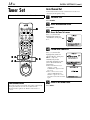
Auto Channel Set
Tuner Set
Perform Auto Channel Set only if channels have not been set
correctly by the Plug&Play setting.
Turn on the TV and select the AV mode.
A Turn on the VCR.
Press POWER.
B Access the Main Menu screen.
Press MENU.
T
W
1
2
3
2
4
5
6
7
8
9
0
1
4
DV
S-VHS
3
C Access the Tuner Set screen.
Press rt to move the
highlight bar (arrow) to
“TUNER SET”, then press OK
or e.
D Perform Auto Channel Set.
Press rt to move the
highlight bar (arrow) to
“AUTO CH SET”, then press
OK or e. You can
automatically set the
receivable channels in your
area in the order of their
frequencies.
● When Auto Channel Set is
complete, “SCAN
COMPLETED” appears on the
TV screen.
● If the scan was unsuccessful,
“SCAN COMPLETED–NO
SIGNAL–” appears on screen.
Check the connections and start
again.
INFORMATION
The VCR selects the correct band (TV or CATV) automatically
during Auto Channel Set. The selected band will be
displayed on the right side of “BAND” on the Tuner Set
screen.
E Return to the normal screen.
Press MENU.
EN
19
Manual Channel Set
You can add the channels you want or delete the channels you
do not want manually.
T
A Turn on the VCR.
W
1
2
Press POWER.
3
2
4
5
6
7
8
9
0
4
B Access the Main Menu screen.
Press MENU.
C Access the Tuner Set screen.
1
DV
3
S-VHS
Press rt to move the
highlight bar (arrow) to
“TUNER SET”, then press OK
or e.
D Access the Manual Channel Set screen.
Press rt to move the
highlight bar (arrow) to
“MANUAL CHANNEL SET”,
then press OK or e.
E Add or skip the desired channels.
To add channels
A Press the number keys to
input a channel number you
want to add.
B Press OK or e to set to
“ADD”.
C Repeat A to B to add other
channels.
To skip channels
A Press rt or the number keys to select a channel
number you want to skip.
B Press OK or e to set to “SKIP”.
C Repeat A and B to skip other channels.
F Return to the normal screen.
Press MENU.
20 EN
INITIAL SETTINGS (cont.)
Cable Box Control
Setting
Place the cable box on top of the VCR. Attach the VCR's
Controller to the top of the VCR with the Controller’s
transmitter pointed towards the cable box’s remote
sensor.
ATTENTION:
The Controller can also control a DBS receiver. If both a cable
box and a DBS receiver are used, position the Controller so its
signal reaches the remote sensors of both the cable box and DBS
receiver.
Cable box
The following procedure is required if you receive your
TV channels through a cable box (descrambler). The
Controller allows the VCR to automatically switch the
cable box channel during timer recording. The Controller
is effective for recording broadcasts that have been
programed using “VCR Plus+ Timer Programing”
(墌 pg. 42) or “Express Timer Programing” (墌 pg. 46).
®
Installing Controller
A Situate the Controller.
Place the Controller so that the path between its
transmitter and the cable box’s remote sensor is
unobstructed.
B Attach the Controller.
Fix securely using the adhesive strip attached on the back
of the Controller.
C Make connections.
If your cable box does not have audio/video output
connectors
Connect the RF output connector on the cable box to the
ANTENNA IN connector on the rear of your VCR.
Your VCR
Controller
(suggested locations)
Cable box
If your cable box has audio/video output connectors
Connect an audio/video cable between the AUDIO/
VIDEO IN connectors on the rear of the VCR and the
audio/video output connectors on the cable box.
NOTE:
When connecting your cable box, refer to its instruction manual.
To RF output
Controller
To Audio/
video
output
Transmitter
D Connect the Controller to VCR.
Connect the Controller to the CABLE BOX connector on
the rear panel.
or
To
ANTENNA
IN
Your VCR
CABLE
BOX
To
AUDIO/
VIDEO IN
How to control the cable box
This VCR has two separate methods to control your cable
box.
● The VCR’s wireless Remote can control your cable box.
This eliminates the need for a separate cable box’s Remote.
● The VCR’s Controller can also control your cable box. This
allows the VCR to change your cable box’s channel
number during timer recording.
Each method must be set up separately. To set up the VCR’s
Remote, refer to page 68. To set up the Controller, go to
page 21.
EN
21
D Access the Initial Set screen.
Press rt to move the
highlight bar (arrow) to
“INITIAL SET”, then press OK
or e.
T
W
1
2
3
4
5
6
7
8
9
2
0
1
4
DV
E Access the Cable Box Set screen.
Press rt to move the
highlight bar (arrow) to
“CABLE BOX SET”, then
press OK or e.
S-VHS
F Select the cable box’s channel.
3
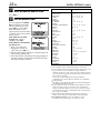
Setting cable box's brand and channel
After installation, set the cable box’s brand and channel
correctly; otherwise, the Controller cannot work
correctly.
Turn on the TV and select the AV mode.
A Turn on the VCR.
Press POWER.
B Turn on the cable box.
Turn on the cable box’s power.
C Access the Main Menu screen on the VCR.
Press MENU.
Your selection depends on how
the cable box is connected to
your VCR.
If the cable box is connected
to your VCR’s ANTENNA IN
connector on the rear panel,
press rt until the channel
number representing the cable
box’s output (CH2 – CH9) appears on the screen.
If the cable box is connected to your VCR’s AUDIO/
VIDEO IN connectors on the rear panel, press rt until
“ON L-1 (REAR)” appears on the screen.
If you do not use a cable box, press rt until “OFF”
appears on the screen.
22 EN
G Access the Cable Box Brand Set screen.
Press OK or e.
H Enter the cable box’s brand.
Press the appropriate number
keys to enter the brand code
from the following list, then
press OK or e and “CABLE
BOX CONTROL IS ON”
appears on the screen for about
5 seconds, then it returns to the
normal screen.
If the cable box’s channel
changes to 9, setting is
complete. Press OK.
If the cable box’s channel does
not change to 9;
A Press rt to move the
highlight bar (arrow) to
“NO”, then press OK or e.
B Repeat step 8 until the cable box’s channel changes to
9 by entering another code.
C If the channel does not change after going through all
the code numbers listed for your model of cable box,
then try all the other numbers.
INITIAL SETTINGS (cont.)
BRAND NAME
CODE
ARCHER
CABLETENNA
CABLEVIEW
CITIZEN
CURTIS
DIAMOND
GC BRAND
GEMINI
GENERAL INSTRUMENTS
HAMLIN
JASCO
JERROLD
NOVAVISION
OAK
PANASONIC
PULSER
RCA
REGAL
REMBRANDT
SAMSUNG
SCIENTIFIC ATLANTA
SIGMA
SL MARX
SPRUCER
STARGATE
TELEVIEW
TOCOM
UNIKA
UNIVERSAL
VIDEOWAY
ZENITH
1, 5, 17
1, 17
15, 16, 17, 21, 25
15, 16, 17, 21, 25
2, 8
1, 17
15, 16, 17, 21, 25
15
1, 4, 6, 11, 12, 15, 28
10, 18, 23
15
1, 4, 6, 11, 12, 15, 28
2, 8
7, 20
13, 14
15, 16, 17, 21, 25
13, 14
10, 18, 23
1, 16, 17
5, 16, 24
2, 8
7, 20
5, 16, 17, 24, 25
13, 14
5, 15, 16, 17, 21, 24, 25
5, 16, 24
1, 4, 16
1, 17
16, 17, 25
3, 9, 22
3, 9, 22
NOTES:
● The Controller may not work with all types of cable box.
● If your cable box does not respond to any code between 1 and
25, you cannot use the Controller to change cable box
channels. In this case, make sure to leave the cable box turned
on and tuned to the proper channel before the scheduled start
time of timer recording.
Contact your cable company about the possibility of
exchanging your current cable box with the one compatible
with your VCR.
● The VCR can only change the cable box channel through the
Controller during timer recording.
● If your cable box cannot be operated with a Remote (because
it has no remote sensor), you cannot use the Controller to
change its channels. Make sure to leave the cable box turned
on and tuned to the proper channel before the scheduled start
time of timer recording.
● If the VCR’s memory backup expires because of a power
failure, set the cable box output channel and brand again.
● For customers in U.S.A.: If you are unable to set the
Controller, contact JVC toll free at 1-800-537-5722.
EN
23
The following procedure is required if you receive
satellite channels through a DBS (Direct Broadcast
Satellite) receiver. The Controller allows the VCR to
automatically switch the DBS receiver’s channel during
timer recording.
DBS Receiver
Control Setting
NOTES:
Place the DBS (Direct Broadcast Satellite) receiver on top
of the VCR. Attach the VCR’s Controller to the top of the
VCR with the Controller’s transmitter pointed towards the
DBS receiver’s remote sensor.
ATTENTION:
The Controller can also control a cable box. If both a DBS
receiver and a cable box are used, position the Controller so its
signal reaches the remote sensors of both the DBS receiver and
cable box.
DBS receiver
● The VCR can automatically change the DBS receiver channels
using the Controller when the VCR has been programed using
“Express Timer Programing” (墌 pg. 46).
Because satellite programing does not use PlusCode, the
Controller cannot change the DBS receiver channels during
“VCR Plus+ Timer Programing” (墌 pg. 42).
● If a cable box is also used, it is recommended that you
connect the DBS receiver to your VCR’s audio/video input
connectors and the cable box to your VCR’s antenna input
terminal.
®
Installing Controller
A Situate the Controller.
Place the Controller so that the path between its
transmitter and the DBS receiver’s remote sensor is
unobstructed.
B Attach the Controller.
Your VCR
Controller
(suggested locations)
DBS receiver
Fix securely using the adhesive strip attached on the back
of the Controller.
C Make connections.
If your DBS receiver does not have audio/video output
connectors
Connect the RF output terminal on the DBS receiver to
the ANTENNA IN connector on the rear of your VCR.
To RF
output
Controller
To Audio/
video
output
Transmitter
or
To
ANTENNA
IN
To
AUDIO/
VIDEO IN
If your DBS receiver has audio/video output connectors
Connect an audio/video cable between the AUDIO/
VIDEO IN connectors on the rear of the VCR and the
audio/video output connectors on the DBS receiver.
NOTE:
When connecting your DBS receiver, refer to its instruction
manual.
D Connect the Controller to VCR.
Connect the Controller to the CABLE BOX connector on
the rear panel.
Your VCR
CABLE
BOX
How to control the DBS receiver
This VCR has two separate methods to control your DBS
receiver.
● The VCR’s wireless Remote can control your DBS receiver.
This eliminates the need for a separate DBS receiver’s
Remote.
● The VCR’s Controller can also control your DBS receiver.
This allows the VCR to change your DBS receiver’s channel
number during timer recording.
Each method must be set up separately. To set up the VCR’s
Remote, refer to page 69. To set up the Controller, go to
page 24.
24 EN
INITIAL SETTINGS (cont.)
D Access the Initial Set screen.
Press rt to move the
highlight bar (arrow) to
“INITIAL SET”, then press OK
or e.
T
W
1
2
3
4
5
6
7
8
9
2
0
1
4
DV
E Access the DBS Receiver Set screen.
Press rt to move the
highlight bar (arrow) to “DBS
RECEIVER SET”, then press
OK or e.
S-VHS
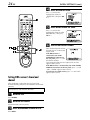
F Select the DBS receiver’s channel.
3
Setting DBS receiver's brand and
channel
After installation, set the DBS receiver’s brand and
channel correctly; otherwise, the Controller cannot work
correctly.
Turn on the TV and select the AV mode.
A Turn on the VCR.
Press POWER.
B Turn on the DBS receiver.
Turn on the DBS receiver’s power.
C Access the Main Menu screen on the VCR.
Press MENU.
Your selection depends on how
the DBS receiver is connected
to your VCR.
If the DBS receiver is
connected to your VCR’s
ANTENNA IN connector on
the rear panel, press rt until
the channel number
representing the DBS receiver’s output (CH3 or CH4)
appears on the screen.
If the DBS receiver is connected to your VCR’s AUDIO/
VIDEO IN connectors on the rear panel, press rt until
“ON L-1 (REAR)” appears on the screen.
If you do not use a DBS receiver, press rt until “OFF”
appears on the screen.
EN
G Access the DBS Receiver Brand Set screen.
Press OK or e.
H Enter the DBS receiver’s brand.
Press the appropriate number
keys to enter the brand code
from the following list, then
press OK or e.
The program currently
received through the DBS
receiver appears for about 10
seconds.
BRAND NAME
CODE
JVC (DISH Network)
ECHOSTAR (DISH Network)
SONY (DSS)
RCA (DSS)
51
51
41
40
If the DBS receiver’s channel
changes to the channel listed
below for your brand, setting
is complete.
JVC ] 100
ECHOSTAR ] 100
SONY ] 205
RCA ] 205
Press OK or e and “DBS RECEIVER CONTROL IS ON”
appears on the screen for about 5 seconds, then it returns
to the normal screen.
If the DBS receiver’s channel does not change as shown
above;
A Press rt to move the highlight bar (arrow) to “NO”,
then press OK or e.
B Repeat step 8.
NOTES:
25
● The Controller may not work with all types of DBS receiver.
● If your DBS receiver does not respond to the code, you cannot
use the Controller to change satellite channels. In this case,
make sure to leave the DBS receiver turned on and tuned to
the proper channel before the scheduled start time of timer
recording.
● The VCR can only change the satellite channel through the
Controller during timer recording.
● If your DBS receiver cannot be operated with a Remote
(because it has no remote sensor), you cannot use the
Controller to change its channels. Make sure to leave the DBS
receiver turned on and tuned to the proper channel before the
scheduled start time of timer recording.
● If the VCR’s memory backup expires because of a power
failure, set the cable box output channel and brand again.
● For customers in U.S.A.: If you are unable to set the Controller,
contact JVC toll free at 1-800-537-5722.
26 EN
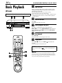
PLAYBACK/RECORDING ON VHS DECK
Basic Playback
(VHS deck)
Turn on the TV and select the AV mode.
A Load a cassette.
Make sure the window side is up, the rear label side is
facing you and the arrow on the front of the cassette is
pointed toward the VCR.
● Do not apply too much pressure when inserting.
● The VCR’s power comes on automatically.
● If the record safety tab has been removed, playback begins
automatically.
B Select the VHS deck.
Press S-VHS.
● The S-VHS button lights on the VCR.
1
3
2
C Find the program start point.
If the tape is advanced past the start point, press
REW (3) or turn the ADVANCED JOG dial on the VCR
to the left. To go forward, press FF (5) or turn the
ADVANCED JOG dial on the VCR to the right.
D Start playback.
Press PLAY (4). “VIDEO CALIBRATION” appears
blinking on the TV screen during automatic tracking.
(墌 pg. 35)
● The VHS playback indicator lights on the VCR.
T
W
1
2
3
4
5
6
7
8
9
2
0
1
S-VHS
Press STOP (8). Then press EJECT (
cassette.
) to remove the
● The VHS playback indicator turns off.
4
DV
E Stop playback.
NOTE:
It is impossible to play back a tape on the VHS deck while the
recording is in progress on the DV deck. When you start
recording on the DV deck during playback on the VHS deck,
playback stops on the VHS deck and recording continues on the
DV deck.
Usable cassettes
3
Full-Size VHS
T-30 (ST-30**)
T-60 (ST-60**)
T90
T-120 (ST-120**)
T-160 (ST-160**)
ST-210**
Compact VHS*
TC-20 (ST-C20**)
TC-30 (ST-C30**)
TC-40 (ST-C40**)
* Compact VHS camcorder recordings can be played on this
VCR. Simply place the recorded cassette into a VHS
Cassette Adapter and it can be used just like any full-sized
VHS cassette.
**This VCR can record on regular VHS and Super VHS
cassettes. While only VHS signals can be recorded on
regular VHS cassettes 1), both VHS and Super VHS signals
can be recorded and played back using Super VHS
cassettes.
1)By using the S-VHS ET function, it is possible to record and
play back with S-VHS picture quality on VHS cassettes
with this VCR.
EN
Basic Recording
A Load a cassette.
(VHS deck)
● The VCR’s power comes on automatically.
Turn on the TV and select the AV mode.
27
Insert a VHS (or S-VHS) cassette with the record safety
tab intact.
B Select the VHS deck.
Press S-VHS.
● The S-VHS button lights on the VCR.
C Choose a program.
On the Remote
Press CH +/– or the number keys.
1
3
2
On the VCR
Push the ADVANCED JOG dial and turn it to the left or
right to select the channel you wish to record.
D Set the tape speed.
Press SP/EP (p). Check the SP/EP indicator on the
VCR’s front display panel to confirm the selected tape
speed.
E Start recording.
Press and hold REC (7) and press PLAY (4) on the
Remote, or press REC (7) on the VCR.
T
● The VHS recording indicator lights on the VCR.
W
1
2
3
2
4
5
6
7
8
9
0
Video Calibration takes place at the beginning of both the
first SP and the first EP recording after inserting the cassette.
(墌 pg. 35)
4
F Pause/Resume recording.
Press PAUSE (9). Press PLAY (4) to resume recording.
1
DV
S-VHS
● You can select channel during the Record Pause mode.
G Stop recording.
Press STOP (8). Then press EJECT (
cassette.
) to remove the
● The VHS recording indicator turns off.
3
NOTE:
It is not possible to record a TV program on both the VHS deck
and the DV deck simultaneously. In addition, it is not possible to
record simultaneously from the same external input.
28 EN
PLAYBACK/RECORDING ON VHS DECK (cont.)
Playback Features
Still Picture/Frame-By-Frame
Playback (On the VCR)
(VHS deck)
1 Pause during playback.
Push the ADVANCED JOG dial.
OR
Press PAUSE (9).
2 Activate frame-by-frame playback.
Turn the ADVANCED JOG dial to the right for forward
frame-by-frame playback, or to the left for reverse frameby-frame playback.
OR
1
3
Press PAUSE (9) to advance a still picture.
2
NOTE:
ADVANCED JOG
dial
Still picture playback stops automatically after 5 minutes to
protect the heads.
To resume normal playback, press PLAY (4) or push
the ADVANCED JOG dial.
T
W
1
2
3
4
5
6
7
8
9
2
0
1
Slow Motion (On the VCR)
During playback, turn the ADVANCED JOG dial one
click to the left for forward slow motion. To play in
reverse slow motion, continue to turn the ADVANCED
JOG dial to the left after selecting all the forward
direction slow motion modes.
4
DV
S-VHS
OR
During still picture, press and hold PAUSE (9) for more
than 2 seconds, then release. Press PAUSE (9) and
release again to return to still picture.
NOTES:
3
JOG/
SHUTTLE
button
JOG dial
SHUTTLE
ring
● During slow motion, some noise may appear on the TV screen.
Press CH+/– to eliminate the noise. However, the VCR will
return to the default setting once a power failure occurs.
● Slow motion playback stops automatically after 5 minutes to
protect the heads.
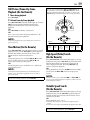
High-Speed (Turbo) Search
(On the VCR)
During playback, turn the ADVANCED JOG dial quickly
to the left or right.
Clean the video heads using a dry cleaning
cassette — TCL-2 — when:
● Rough, poor picture appears while a tape is played back.
● The picture is unclear or no picture appears.
● “USE CLEANING CASSETTE” appears on the screen (only
with “SUPERIMPOSE” set to “ON” (墌 pg. 71)). “U:01”
appears on the front display panel.
Variable Speed Search (On the VCR)
During playback, turn the ADVANCED JOG dial to the
right for forward variable-speed search, or to the left for
reverse variable-speed search.
To resume normal playback, press PLAY (4).
EN
Still Picture/Frame-By-Frame
Playback (On the Remote)
1 Pause during playback.
29
You can also use the Remote's JOG dial/SHUTTLE ring for
the operations. First press the JOG/SHUTTLE button on the
Remote so that the button lights up before use. Refer to the
SHUTTLE ring illustration below as you read the procedures.
Press PAUSE (9).
2 Activate frame-by-frame playback.
Press JOG/SHUTTLE so that the button lights up. Turn the
JOG dial to the right for forward frame-by-frame
playback, or to the left for reverse frame-by-frame
playback.
OR
Press PAUSE (9) to advance a still picture.
OR
Press w for reverse frame-by-frame playback or e for
forward frame-by-frame playback.
NOTE:
Still picture playback stops automatically after 5 minutes to
protect the heads.
Slow Motion (On the Remote)
Press JOG/SHUTTLE so that the button lights up. During
playback or still, turn the SHUTTLE ring to the right for
forward slow motion, or to the left for reverse slow
motion. Release to return to still picture.
OR
During still picture, press and hold PAUSE (9) for more
than 2 seconds, then release. Press PAUSE (9) and
release again to return to still picture.
OR
During still picture, press and hold w or e. Release to
return to still picture.
NOTES:
● During slow motion, some noise may appear on the TV screen.
Press CH+/– to eliminate the noise. However, the VCR will
return to the default setting once a power failure occurs.
● Slow motion playback stops automatically after 5 minutes to
protect the heads.
To resume normal playback, press PLAY (4).
Reverse
Reverse
search
4 steps
Forward
Reverse
play
Reverse
slow
motion
2 steps
Slow
motion
2 steps
Normal
play
Forward
search
4 steps
High-Speed (Turbo) Search
(On the Remote)
Press JOG/SHUTTLE so that the button lights up. During
playback or still, turn the SHUTTLE ring all the way to the
right for forward high-speed search, or to the left for
reverse high-speed search. Releasing SHUTTLE ring
resumes still picture playback.
OR
During playback or still, press FF (5) for forward highspeed search, or REW (3) for reverse high-speed
search.
NOTE:
For short searches, press and hold FF (5) or REW (3) for
over 2 seconds during playback or still picture. When released,
normal playback resumes.
Variable Speed Search
(On the Remote)
Press JOG/SHUTTLE so that the button lights up. During
playback or still, turn the SHUTTLE ring to the right for
forward variable-speed search, or to the left for reverse
variable-speed search.
OR
During playback, press w or e.
● The more times you press, the faster the playback picture
moves.
● To decrease speed, press the button for the opposite direction.
To resume normal playback, press PLAY (4).
30 EN
PLAYBACK/RECORDING ON VHS DECK (cont.)
Index Search
Your VCR automatically marks
index codes at the beginning of
each recording. This function gives
you quick access to any one of 9
index codes in either direction.
INDEX 1
NOTE:
1
3
2
Before starting, make sure the VCR
is in the Stop mode.
Activate Index Search.
Press w or e (2 or 6). “INDEX -1” or “INDEX 1” is
displayed on the TV screen and search begins in the
corresponding direction.
T
● To access index codes 2 through 9, press w or e repeatedly
until the correct index number is displayed.
Example:
To locate the beginning of B from the current position, press w
twice.
To locate the beginning of D from the current position, press e
once.
Current position
W
1
2
3
4
5
6
7
8
9
2
0
4
Index number
1
DV
S-VHS
● When the specified index code is located, playback begins
automatically.
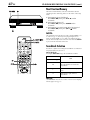
Next Function Memory
The Next Function Memory “tells” the VCR what to do after
rewinding. Before continuing, make sure the VCR is in the Stop
mode.
3
Repeat Playback
Your VCR can automatically play back the whole tape 100 times
repeatedly.
1 Start playback.
Press PLAY (4).
2 Activate Repeat Playback.
Press PLAY (4) and hold for over 5 seconds, then release.
● The Play indicator ( u) on the front display panel blinks
slowly.
● After playing back a tape 100 times, the VCR stops
automatically.
3 Stop Repeat Playback.
Press STOP (8) at any time.
● Pressing PLAY (4), REW (3), FF (5) or PAUSE (9) also
stops Repeat Playback.
a- For Automatic Start Of Playback
Press REW (3), then press PLAY (4) within
2 seconds.
b- For Automatic Power Off
Press REW (3), then press POWER within
2 seconds.
c- For Automatic Cassette Ejection After Tape Rewind
Press REW (3), then press EJECT ( ) within
2 seconds.
NOTE:
The Automatic Power Off does not work if “AUTO TIMER” is set
to “ON” (墌 pg. 71) and if any timer programing has been
made. If “AUTO TIMER” is set to “ON”, the VCR directly goes
into the Timer-Standby mode at the same time when the POWER
is pressed for the Automatic Power Off.
EN
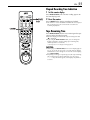
31
Manual Tracking
Your VCR is equipped with automatic tracking control. During
playback, you can override this and adjust the tracking manually
by pressing the CH buttons.
T
W
1
2
3
4
5
6
7
8
9
2
0
1 Override automatic tracking.
Press p on the Remote.
4
2 Adjust the tracking manually.
Press CH + or –.
● Press p again to return to automatic tracking.
1
DV
S-VHS
NOTE:
When a new tape is inserted, the VCR enters the automatic
tracking mode automatically.
Soundtrack Selection
3
Your VCR is capable of recording three soundtracks (HI-FI L,
HI-FI R and NORM) and will play back the one you select.
During Playback
Pressing A. MONITOR changes the soundtrack as follows:
● You can also select the soundtrack on the VHS MODE SET
screen. (墌 pg. 75, “AUDIO MONITOR”)
TRACK
USE
On-Screen Display
H I-F I
Hi-Fi sound is played back
H I-F I L
Sound on the left Hi-Fi channel is
played back
H I-F I R
Sound on the right Hi-Fi channel is
played back
NORM
Sound on the normal track is played
back
NORM
H I-F I
Both sounds on the Hi-Fi track and
normal track are mixed and played
back
NOTES:
● “HI-FI” should normally be selected. In this mode, Hi-Fi stereo
tapes are played back in stereo, and the normal audio track is
played back automatically for tapes with only normal audio.
● “SUPERIMPOSE” must be set to “ON” or the on-screen
displays will not appear (墌 pg. 71).
32 EN
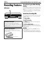
PLAYBACK/RECORDING ON VHS DECK (cont.)
Recording Features
Record One Program While Watching
Another
(VHS deck)
Once recording is in progress, all you need to do is to set
the channel controls on the TV for the station you wish to
view.
● The program selected with the TV’s channel controls appears
on the TV screen, while the one selected with the VCR’s CH
buttons is recorded on the tape.
Instant Timer Recording (ITR)
1
3
2
This easy method lets you record for from 30 minutes to 6 hours
(selectable in 30-min. increments), and shuts the VCR off after
recording is finished.
1 Start recording.
Press REC (7) on the VCR.
2 Engage the ITR mode.
Recording Resume Function
If there is a power outage during recording, Instant Timer
Recording (in the right column) or timer recording
(墌 pg. 42, 46, 48), the recording will resume automatically
when power is restored to the VCR unless the VCR’s memory
backup has expired.
Accidental erasure prevention
To prevent accidental recording on a recorded cassette,
remove its safety tab. To record on it later, cover the hole
with adhesive tape.
Record safety tab
Press REC (7) again. “o” blinks and “0:30” appears on
the front display panel.
3 Set the recording duration.
If you want to record for more than 30 minutes, press
REC (7) to extend the time. Each press extends recording
time by 30 minutes.
NOTES:
● You can only perform ITR using the REC (7) button on the
VCR’s front panel.
● You can play back a tape on DV deck while using the VHS
deck for Instant Timer Recording. However, remember that the
VCR will turn itself off when the Instant Timer Recording ends.
EN
33
Elapsed Recording Time Indication
1 Set the counter display.
Press DISPLAY/OSD until a counter reading appears on
the front display panel.
T
2 Reset the counter.
W
1
2
3
4
5
6
7
8
9
2
0
Press C.RESET before starting recording or playback.
● The counter is reset to “0:00:00” and shows the exact elapsed
time as the tape runs. You can check the exact time of a
recording or playback.
4
Tape Remaining Time
1
DV
S-VHS
Press DISPLAY/OSD until the time remaining on the tape
appears on the front display panel.
● The front display panel shows the tape remaining time with
“z” displayed.
● By pressing the DISPLAY/OSD button, you can change the
display to show the counter reading, tape remaining time,
channel position* or clock time.
* Channel position is not displayed during playback.
3
NOTES:
● When you press DISPLAY/OSD, the on-screen display appears
(墌 pg. 10) on the TV screen for 5 seconds, then the displays
other than the counter disappears. To clear the counter display,
press DISPLAY/OSD.
● Depending on the type of tape being used, the tape remaining
time reading may not appear right away, or is not correct.
“– –:– –” may sometimes appear, or the display may blink on
occasion.
34 EN
PLAYBACK/RECORDING ON VHS DECK (cont.)
Retake
You can cut out unnecessary parts of a TV program while you are
recording it.
End of program
1
3
2
Program
Unnecessary
part
Beginning of program
Unnecessary
part
Program
Recorded part
ADVANCED JOG
dial
Go back to end of program to cut out
unnecessary part
1 Engage the Record-Pause mode.
Press PAUSE (9) during recording.
2 Locate the start point.
T
W
1
2
3
2
4
5
6
7
8
9
0
Turn the ADVANCEDJOG dial to the left or right (or hold
down REW (3) or FF (5)) and release it when you
reach the point where you want to resume recording.
● Your VCR returns to the Record-Pause mode.
4
3 Resume recording.
Press PLAY (4) when you wish to resume recording.
1
DV
S-VHS
Second Audio Recording
This VCR’s built-in MTS decoder enables reception of
Multichannel TV Sound broadcast. To record a SAP
program received, set “2ND AUDIO RECORD” to “ON”.
(墌 pg. 71)
NOTES:
3
When the channel is changed on the VCR;
● The “STEREO” indicator appears on the screen for about
5 seconds if the program is a stereo broadcast.
● The “SAP” indicator appears on the screen for about
5 seconds if the program is a SAP broadcast.
● Both indicators appear when a stereo program is accompanied
by SAP sound.
EN
Active Video
Calibration
(VHS deck)
Active Video Calibration checks the condition of the tape
in use during playback and recording, and compensates
to provide the highest-possible playback and recording
pictures. You can set “VIDEO CALIBRATION” to “ON” or
“OFF” to your preference (墌 pg. 73).
Playback
The VCR assesses the quality
of the tape once you initiate
playback.
● The VCR adjusts the playback
picture quality based on the
quality of the tape in use.
● Video Calibration is active
during automatic tracking. The
Video Calibration screen
appears blinking on the TV screen.
NOTES:
● When watching a tape recorded with “VIDEO CALIBRATION”
set to “ON”, it is recommended that you leave VIDEO
CALIBRATION on during playback as well.
● When watching a rental tape or one recorded on another VCR,
or when using this VCR as the player for editing, set VIDEO
CALIBRATION to your preference (墌 pg. 73).
● The Video Calibration screen only appears at the beginning of
automatic tracking. Even though it doesn’t appear after that,
the Video Calibration function is operative.
35
Recording
The VCR assesses the quality
of the tape once you initiate
recording.
DURING VIDEO
CALIBRATION
● The VCR spends approximately
7 seconds assessing the
condition of the tape, then
begins recording.
NOTES:
● The Video Calibration works for
both SP and EP modes only
after a tape has been inserted
and the Record mode is first
initiated. It does not work
during recording.
● In the case of timer recordings,
the Video Calibration works
before recording is initiated.
● Once the cassette is ejected,
the Video Calibration data is
cancelled. The next time the
cassette is used for recording,
Video Calibration is reperformed.
VIDEO CALIBRATION
COMPLETE
ATTENTION
Since the Video Calibration works before recording actually
starts, there is a delay of approximately 7 seconds after
REC (7) and PLAY (4) on the Remote are pressed, or
REC (7) on the VCR is pressed. To make sure you record the
desired scene or program in its entirety, first perform the
following steps:
A Press and hold PAUSE (9) and press REC (7) to engage
the Record Pause mode.
● The VCR then automatically checks the condition of the
tape and, after approximately 7 seconds, re-enters Record
Pause mode.
B Press PLAY (4) to start recording.
If you want to bypass the Video Calibration and begin
recording immediately, set “VIDEO CALIBRATION” to “OFF”
(墌 pg. 73).
36 EN
PLAYBACK/RECORDING ON DV DECK
Basic Playback
(DV deck)
Turn on the TV and select the AV mode.
A Load a cassette.
Make sure the window side is up, the rear label side is
facing you and the arrow on the front of the cassette is
pointed toward the VCR.
● Do not apply too much pressure when inserting.
● The VCR’s power comes on automatically.
● If the erase protection switch is set to “SAVE”, playback begins
automatically. It takes about 15 seconds until the playback
picture appears.
B Select the DV deck.
Press DV.
● The DV button lights on the VCR.
1
3
2
C Find the program start point.
If the tape is advanced past the start point, press
REW (3) or turn the ADVANCED JOG dial to the left.
To go forward, press FF (5) or turn the ADVANCED
JOG dial to the right.
D Start playback.
Press PLAY (4).
● The DV playback indicator lights on the VCR.
T
E Stop playback.
W
1
2
3
2
4
5
6
7
8
9
0
Press STOP (8). Then press EJECT (
cassette.
● The DV playback indicator turns off.
4
Usable cassettes
Only cassettes marked
deck.
1
DV
S-VHS
) to remove the
can be used with the DV
NOTE:
When you record a tape on the DV deck with the recording
speed set to “LP”, it is recommended to play back the tape on
this DV deck. Digital video recorder from other manufacturers
may not be able to play back the tape properly.
3
EN
Basic Recording
A Load a cassette.
(DV deck)
● The VCR’s power comes on automatically.
Turn on the TV and select the AV mode.
37
Insert a Mini DV cassette with the erase protection switch
set to “REC”.
B Select the DV deck.
Press DV.
● The DV button lights on the VCR.
C Choose a program.
On the Remote
Press CH +/– or the number keys.
1
3
2
On the VCR
Push the ADVANCED JOG dial and turn it to the left or
right to select the channel you wish to record.
D Set the tape speed.
Press SP/LP (p). Check the SP/LP indicator on the
VCR’s front display panel to confirm the selected tape
speed.
E Start recording.
Press and hold REC (7) and press PLAY (4) on the
Remote, or press REC (7) on the VCR.
T
● The DV recording indicator lights on the VCR.
W
1
2
3
2
4
5
6
7
8
9
0
1
4
DV
S-VHS
F Pause/Resume recording.
Press PAUSE (9). Press PLAY (4) to resume recording.
● You can select channel during the Record Pause mode.
G Stop recording.
Press STOP (8). Then press EJECT (
cassette.
) to remove the
● The DV recording indicator turns off.
NOTES:
3
● It is not possible to record a TV program on both the VHS deck
and the DV deck simultaneously. In addition, it is not possible
to record simultaneously from the same external input.
● When you record a tape on the DV deck with the recording
speed set to “LP”, it is recommended to play back the tape on
this DV deck. Digital video recorder from other manufacturers
may not be able to play back the tape properly.
38 EN
PLAYBACK/RECORDING ON DV DECK (cont.)
Playback Features
Still Picture/Frame-By-Frame
Playback (On the VCR)
(DV deck)
1 Pause during playback.
Push the ADVANCED JOG dial.
OR
Press PAUSE (9).
2 Activate frame-by-frame playback.
Turn the ADVANCED JOG dial to the right for forward
frame-by-frame playback, or to the left for reverse frameby-frame playback.
OR
1
3
Press PAUSE (9) to advance a still picture.
2
NOTE:
ADVANCED JOG
dial
T
Still picture playback stops automatically after 3 minutes to
protect the heads.
To resume normal playback, press PLAY (4) or push
the ADVANCED JOG dial.
W
1
2
3
4
5
6
7
8
9
2
0
1
Slow Motion (On the VCR)
During playback, turn the ADVANCED JOG dial one
click to the left for forward slow motion. To play in
reverse slow motion, continue to turn the ADVANCED
JOG dial to the left.
4
DV
OR
S-VHS
During still picture, press and hold PAUSE (9) for more
than 2 seconds, then release. Press PAUSE (9) and
release again to return to still picture.
NOTE:
Forward slow motion playback stops automatically after 1
minute, reverse slow motion playback after 30 seconds to
protect the heads.
3
JOG/
SHUTTLE
button
JOG dial
SHUTTLE
ring
High-Speed (Turbo) Search
(On the VCR)
During playback, turn the ADVANCED JOG dial quickly
to the left or right.
Variable Speed Search (On the VCR)
ATTENTION
Picture may appear distorted during variable speed search.
Clean the video heads using a dry cleaning
cassette — M-DV12CL — when:
● No picture during playback.
● Blocks of noise appear during playback.
● “USE CLEANING CASSETTE” appears on the screen (only
with “SUPERIMPOSE” set to “ON” (墌 pg. 71)).
During playback, turn the ADVANCED JOG dial to the
right for forward variable-speed search, or to the left for
reverse variable-speed search.
To resume normal playback, press PLAY (4).
EN
Still Picture/Frame-By-Frame
Playback (On the Remote)
1 Pause during playback.
39
You can also use the Remote's JOG dial/SHUTTLE ring for
the operations. First press the JOG/SHUTTLE button on the
Remote so that the button lights up before use. Refer to the
SHUTTLE ring illustration below as you read the procedures.
Press PAUSE (9).
2 Activate frame-by-frame playback.
Press JOG/SHUTTLE so that the button lights up. Turn the
JOG dial to the right for forward frame-by-frame
playback, or to the left for reverse frame-by-frame
playback.
OR
Press PAUSE (9) to advance a still picture.
OR
Press w for reverse frame-by-frame playback or e for
forward frame-by-frame playback.
NOTE:
Still picture playback stops automatically after 3 minutes to
protect the heads.
Reverse
Slow Motion (On the Remote)
Reverse
search
3 steps
Press JOG/SHUTTLE so that the button lights up. During
playback or still, turn the SHUTTLE ring to the right for
forward slow motion, or to the left for reverse slow
motion. Release to return to still picture.
OR
During still picture, press and hold PAUSE (9) for more
than 2 seconds, then release. Press PAUSE (9) and
release again to return to still picture.
OR
During still picture, press and hold w or e. Release to
return to still picture.
NOTE:
Forward slow motion playback stops automatically after 1
minute, reverse slow motion playback after 30 seconds to
protect the heads.
To resume normal playback, press PLAY (4).
Forward
Reverse
play
Reverse
slow
motion
1 step
Slow
motion
1 step
Normal
play
Forward
search
3 steps
High-Speed (Turbo) Search
(On the Remote)
Press JOG/SHUTTLE so that the button lights up. During
playback or still, turn the SHUTTLE ring all the way to the
right for forward high-speed search, or to the left for
reverse high-speed search. Releasing SHUTTLE ring
resumes still picture playback.
OR
During playback or still, press FF (5) for forward highspeed search, or REW (3) for reverse high-speed
search.
NOTE:
For short searches, press and hold FF (5) or REW (3) for
over 2 seconds during playback or still picture. When released,
normal playback resumes.
Variable Speed Search
(On the Remote)
Press JOG/SHUTTLE so that the button lights up. During
playback or still, turn the SHUTTLE ring to the right for
forward variable-speed search, or to the left for reverse
variable-speed search.
OR
During playback, press w or e.
● The more times you press, the faster the playback picture
moves.
● To decrease speed, press the button for the opposite direction.
To resume normal playback, press PLAY (4).
40 EN
PLAYBACK/RECORDING ON DV DECK (cont.)
Next Function Memory
The Next Function Memory “tells” the VCR what to do after
rewinding. Before continuing, make sure the VCR is in the Stop
mode.
1
3
2
a- For Automatic Start Of Playback
Press REW (3), then press PLAY (4) within
2 seconds.
b- For Automatic Power Off
Press REW (3), then press POWER within
2 seconds.
c- For Automatic Cassette Ejection After Tape Rewind
Press REW (3), then press EJECT ( ) within
2 seconds.
NOTE:
The Automatic Power Off does not work if “AUTO TIMER” is set
to “ON” (墌 pg. 71) and if any timer programing has been
made. If “AUTO TIMER” is set to “ON”, the VCR directly goes
into the Timer-Standby mode at the same time when the POWER
is pressed for the Automatic Power Off.
T
W
1
2
3
4
5
6
7
8
9
2
0
Soundtrack Selection
Your VCR is capable of recording two soundtracks (L and R) and
will play back the one you select.
During Playback
4
Pressing A. MONITOR changes the soundtrack as follows:
TRACK
USE
1
DV
S-VHS
On-Screen Display
L+R
Both sounds on the left channel and
the right channel are mixed and
played back
L
Sound on the left channel is played
back
R
Sound on the right channel is
played back
NOTE:
“SUPERIMPOSE” must be set to “ON” or the on-screen displays
will not appear (墌 pg. 71).
EN
41
Recording Features
Record One Program While Watching
Another
(DV deck)
Once recording is in progress, all you need to do is to set
the channel controls on the TV for the station you wish to
view.
● The program selected with the TV’s channel controls appears
on the TV screen, while the one selected with the VCR’s CH
buttons is recorded on the tape.
Instant Timer Recording (ITR)
1
3
2
This easy method lets you record for from 30 minutes to 2 hours
(selectable in 30-min. increments), and shuts the VCR off after
recording is finished.
1 Start recording.
Press REC (7) on the VCR.
2 Engage the ITR mode.
Press REC (7) again. “o” blinks and “0:30” appears on
the front display panel.
T
1
W
2
3
2
4
5
6
7
8
9
0
4
Recording Resume Function
If there is a power outage during recording, Instant Timer
Recording (in the right column) or timer recording
(墌 pg. 42, 46, 48), the recording will resume automatically
when power is restored to the VCR unless the VCR’s memory
backup has expired.
Accidental erasure prevention
To prevent accidental recording on a recorded cassette, set
its erase protection switch to “SAVE”. To record on it later, set
the switch to “REC”.
Erase protection switch
Second Audio Recording
This VCR’s built-in MTS decoder enables reception of
Multichannel TV Sound broadcast. To record a SAP
program received, set “2ND AUDIO RECORD” to “ON”.
(墌 pg. 71)
NOTES:
When the channel is changed on the VCR;
● The “STEREO” indicator appears on the screen for about
5 seconds if the program is a stereo broadcast.
● The “SAP” indicator appears on the screen for about
5 seconds if the program is a SAP broadcast.
● Both indicators appear when a stereo program is accompanied
by SAP sound.
3 Set the recording duration.
If you want to record for more than 30 minutes, press
REC (7) to extend the time. Each press extends recording
time by 30 minutes.
NOTE:
You can only perform ITR using the REC (7) button on the
VCR’s front panel.
Time Code
During recording, a time code is recorded on the tape. This time
code is used to confirm the position on the tape when playing
back or editing a tape. To perform Random Assemble Editing
(墌 pg. 64), time code is necessary.
Press DISPLAY/OSD until the time code on the tape
appears on the front display panel.
● By pressing the DISPLAY/OSD button, you can change the
display to show the time code, channel position*, clock time.
* Channel position is not displayed during playback.
NOTES:
The presence of a blank (unrecorded) portion in the middle of a
tape can result in misoperation.
A “blank portion” of a tape is a section where nothing is
recorded on the tape. If you start recording in a blank portion of
a tape, the time codes will start from “0:00:00” again. If identical
time codes are recorded in two different places on a tape,
Random Assemble Editing and other similar functions might not
operate properly.
In the following cases, you should play back the tape and
confirm where a scene ends, and then begin recording from
there:
● When starting recording in the middle of a tape on which a
recording has already been made.
● When you finish recording on a tape, then played back that
recording in order to check it, and now wish to continue
recording.
● When you lost power or the batteries died while you were
recording with a camcorder.
42 EN
TIMER RECORDING
VCR Plus+ Timer
Programing
®
With the VCR Plus+ system, timer programing is greatly
simplified because each TV program has a corresponding
code number which your VCR is able to recognize.
Before performing the VCR Plus+ Timer Programing:
● Make sure that the VCR’s built-in clock is set properly.
● Turn on the TV and select the AV mode.
A Turn on the VCR.
Press POWER.
B Load a cassette.
Insert a VHS (or S-VHS) cassette with the record safety
tab intact.
OR
Insert a Mini DV cassette with the erase protection switch
set to “REC”.
C Select the deck.
Press S-VHS or DV.
D Access the PlusCode No. screen.
Press PROG.
T
W
1
2
3
4
5
6
7
8
9
2
0
4
● The clock must be set to access
the PlusCode No. screen. If
you have not set the clock, the
Main Menu screen appears
after an error message is
displayed. Refer to “Plug &
Play Set” (墌 pg. 14) or “Clock
Set” (墌 pg. 16).
E Enter the PlusCode number.
1
DV
S-VHS
Press the number keys to
enter the PlusCode number
of a program you wish to
record. Then press OK.
● If you make a mistake, press
CANCEL and input the correct
number.
3
F Access the VCR Plus+ Program screen.
The VCR Plus+ Program
screen appears (if you’re just
starting out and you have
selected the VHS deck, “VHS
PROGRAM 1” appears).
IMPORTANT
Make sure the channel position number you wish to record is
displayed; if not, see “Changing VCR Plus+ Setting” on
page 44 and set the Guide Channel number correctly.
®
● If the number you entered is invalid, “ERROR” appears on the
TV screen. Press CANCEL and input a valid PlusCode number.
● If the “GUIDE CHANNEL SET” screen appears, see
“ATTENTION” on page 43.
EN
G Set the tape speed.
For the VHS deck
Press SP/EP (p).
For the DV deck
Press SP/LP (p).
H Return to the normal screen.
Press PROG or OK. “PROGRAM COMPLETED” appears
on the TV screen for about 5 seconds, then the normal
screen appears. If “PROGRAM NOT COMPLETED
PROGRAM OVERLAP” appears on the TV screen, see
page 51.
● Repeat steps 3 – 8 for each additional program.
I Engage the VCR’s timer mode.
Press TIMER. The VCR turns off automatically and “#”
appears on the front display panel.
● To disengage the timer mode, press TIMER again.
Cable Box or DBS Receiver Users
To timer-record a cable or satellite broadcast using the VCR
plus+ system:
A Perform “Cable Box Control Setting” (墌 pg. 20) or “DBS
Receiver Control Setting” (墌 pg. 23).
B Perform steps 1 – 9.
C Leave the power of cable box or DBS receiver on.
IMPORTANT
If you have moved to a different area or if a broadcasting
station's channel number has been changed, the wrong VCR
CH or CABLE CH number will be displayed on the VCR
Plus+ program screen in step 6. When this happens, set the
correct Guide Channel number for that station. (墌 pg. 44,
“Changing VCR Plus+ Setting”)
®
43
NOTES:
● To Change The Stop Time . . .
. . . press STOP +/– in step 6. You can compensate for
anticipated program schedule delays.
● To Timer-Record Weekly Or Daily Serials . . .
. . . in step 6, press WEEKLY (number key “9”) for weekly
serials or DAILY (M–F) (number key “8”) for daily serials
(Monday — Friday). Either “WEEKLY” or “DAILY” appears on
the TV screen. Pressing the button again makes the
corresponding indication disappear.
● In case of a power failure after programing, the VCR’s memory
backup keeps your selections for approximately 10 minutes.
● You can program each deck to timer-record as many as 6
programs. If you try to program the VCR to record a seventh,
“PROGRAM FULL” appears on the TV screen. To record the
extra program, you must first cancel any unnecessary
programs (墌 pg. 50).
● It is not possible to timer-record the same program on both the
VHS deck and the DV deck simultaneously.
● During timer recording, it is not possible to change the
recording deck (VHS or DV).
● If the times that are programed for recording on the DV deck
and on the VHS deck overlap, the earlier start time takes
precedence. If the start times are the same, the VHS deck takes
precedence.
ATTENTION
Guide Channel Number Set
“GUIDE CHANNEL SET” appears after performing step 6 if
the Guide Channel number for the PlusCode number you
entered has not been set.
If you want to set the Guide Channel number for the TV or
cable station, press number keys or rt to input the channel
position number on which your VCR or cable box receives
that station, then press OK or e to set the Guide Channel
number. VCR Plus+ Program screen appears.
If you receive your channels
with a cable box and if you
have properly set your
Controller, “CABLE CH”
appears in place of “VCR
CH”. If not, refer to pages 20.
44 EN
TIMER RECORDING (cont.)
Changing VCR
Plus+ Setting
®
Turn on the TV and select the AV mode.
The VCR Plus+ programing system assigns a VCR Plus+
guide channel to the TV channels and the cable
channels. These guide channel numbers are also called
the VCR Plus+ channel codes. Most TV listings have a
section, usually a chart, indicating the guide channel
numbers assigned to each station.
To ensure that VCR Plus+ timer recording operates
correctly, it is necessary to set the VCR Plus+ “Guide
Channel Set” for each station.
If you have moved to a different area or if a broadcasting
station’s channel number has been changed, perform the
following steps to set the correct guide channel number.
NOTES:
T
W
1
2
3
4
5
6
7
8
9
2
0
● In many instances, the VCR Plus+ guide channel numbers for
cable and broadcast TV stations DO NOT match the channel
number on which it is received by your VCR or cable box.
Check your TV listing, or contact your cable supplier for
details.
● Many TV stations can be viewed on cable. Check your TV
listing, or contact your cable supplier for details.
Guide Channel Number Set
4
A Turn on the VCR.
1
DV
S-VHS
Press POWER.
B Access the Main Menu screen.
Press MENU.
3
C Access the Initial Set screen.
Press rt to move the highlight bar (arrow) to “INITIAL
SET”, then press OK or e.
D Access the Guide Channel Set screen.
Press rt to move the highlight bar (arrow) to “GUIDE
CHANNEL SET”, then press OK or e.
E Enter the Guide Channel number.
Press rt or the number keys
to select the VCR Plus+ guide
channel number as shown in
the TV listing, then press OK or
e.
● If you receive your channels with
a cable box and if you have
properly set your Controller,
“CABLE CH” appears in place of
“VCR CH”. If not, perform
“Cable Box Control Setting”
(墌 pg. 20).
GUIDE CHANNEL SET
GUIDE CH :
VCR CH :
6
––
PRESS NUMBER KEY (0–9)
OR ( , ), THEN (OK)
PRESS (MENU) TO END
(Example)
When inputting the Guide
Channel number 6 for WNJU
(ind.).
EN
45
F Enter the receiving channel position number.
T
Press rt or the number keys
to select the number of the
channel on which the guide
channel’s broadcasts are
received, then press OK or e.
W
1
2
3
2
4
5
6
7
8
9
0
● Repeat steps 5 and 6 as
necessary.
GUIDE CHANNEL SET
GUIDE CH :
VCR CH :
6
47
PRESS NUMBER KEY (0–9)
OR ( , ), THEN (OK)
PRESS (MENU) TO END
(Example) If WNJU (ind.) is
received on channel
position 47.
4
G Return to the normal screen.
1
DV
S-VHS
Press MENU.
Guide Channel Number
3
“Guide Channel (GUIDE CH) number” refers to the assigned
TV station numbers, according to broadcast area, for the VCR
Plus+ timer recording. The Guide Channel numbers can be
found in most TV listings.
46 EN
TIMER RECORDING (cont.)
Express Timer
Programing
If you do not know the PlusCode number for the program
you wish to record, use the following procedure to set
your VCR to timer-record the program.
Before performing Express Timer Programing:
● Make sure that the VCR’s built-in clock is set properly.
● Turn on the TV and select the AV mode.
A Turn on the VCR.
Press POWER.
B Load a cassette.
Insert a VHS (or S-VHS) cassette with the record safety
tab intact.
OR
Insert a Mini DV cassette with the erase protection switch
set to “REC”.
C Select the deck.
Press S-VHS or DV.
D Access the PlusCode screen.
Press PROG.
T
W
1
2
3
2
4
5
6
7
8
9
0
1
4
DV
S-VHS
E Access the Program screen.
Press START+/–. (If you’re
just starting out and you have
selected the VHS deck, “VHS
PROGRAM 1” appears.)
F Enter the program start time.
Press START+/– to enter the
time you want recording to
start.
3
● Press and hold START+/– to
move in 30-minute
increments, or press and
release repeatedly to move 1
minute at a time.
G Enter the program stop time.
Press STOP+/– to enter the time you want recording to
stop.
● Press and hold STOP+/– to move in 30-minute increments, or
press and release repeatedly to move 1 minute at a time.
EN
H Enter the program date.
Press DATE+/–.
● The current date appears on the TV screen. The date you enter
appears in its place.
I Enter the channel position.
Press CH+/–.
● If you are using a DBS receiver, see “ATTENTION FOR DBS
RECEIVER USERS” in the right column.
● Holding down CH +/– rapidly scans through the channels.
J Set the tape speed.
For the VHS deck
Press SP/EP (p).
For the DV deck
Press SP/LP (p).
K Return to the normal screen.
Press PROG or OK. “PROGRAM COMPLETED” appears
on the TV screen for about 5 seconds, then the normal
screen appears. If “PROGRAM NOT COMPLETED
PROGRAM OVERLAP” appears on the TV screen, see
page 51.
● Repeat steps 3 – 11 for each additional program.
L Engage the VCR’s timer mode.
Press TIMER. The VCR turns off automatically and “#”
appears on the front display panel.
● To disengage the timer mode, press TIMER again.
47
NOTES:
● To Timer-Record Weekly Or Daily Serials . . .
. . . anytime during steps 5 through 10, press WEEKLY
(number key “9”) for weekly serials or DAILY (M–F) (number
key “8”) for daily serials (Monday – Friday). Either “WEEKLY”
or “DAILY” appears on the TV screen. Pressing the button
again makes the corresponding indication disappear.
● You can program each deck to timer-record as many as 6
programs. If you try to program the VCR to record a seventh,
“PROGRAM FULL” appears on the TV screen. To record the
extra program, you must first cancel any unnecessary
programs (墌 pg. 50).
● In case of a power failure after programing, the VCR’s memory
backup keeps your selections for approximately 10 minutes.
● Programs that start after midnight must have the next day’s
date.
● You can program the timer while a regular recording is in
progress; the on-screen menu will not be recorded.
● It is not possible to timer-record the same program on both the
VHS deck and the DV deck simultaneously.
● During timer recording, it is not possible to change the
recording deck (VHS or DV).
● If the times that are programed for recording on the DV deck
and on the VHS deck overlap, the earlier start time takes
precedence. If the start times are the same, the VHS deck takes
precedence.
Cable Box or DBS Receiver Users
To timer-record a cable or satellite broadcast using Express
Timer Programing:
A Perform “Cable Box Control Setting” on page 20 or “DBS
Receiver Control Setting” on page 23.
B Perform steps 1 – 12.
C Leave the power of cable box or DBS receiver on.
ATTENTION FOR DBS RECEIVER USERS
If you are using a DBS receiver (unless “DBS RECEIVER SET”
is set to “OFF” 墌 pg. 24), the band indication (TV, CATV or
DBS) appears under the channel number indication.
TV: To timer-record a regular
TV broadcast received
on the VCR.
CATV: To timer-record a cable
TV broadcast received
on the VCR, or through a
cable box (unless
“CABLE BOX SET” is set
to “OFF” 墌 pg. 21).
DBS: To timer-record a satellite broadcast received through
a DBS receiver.
NOTE:
If “BAND” is set to “TV” on the Tuner Set screen (墌 pg. 18)
and “CABLE BOX SET” is set to “OFF” on the Cable Box Set
screen (墌 pg. 21), “CATV” will not be displayed on the
Program screen; If “BAND” is set to “CATV” or “CABLE BOX
SET” is set to “ON”, “TV” will not be displayed.
If the channel number entered requires that the band be set,
“7=DBS” is displayed on the screen.
If this happens, press the number key “7 (DBS)” to select
“DBS”.
48 EN
TIMER RECORDING (cont.)
You can program a timer recording that starts within 24
hours using the ADVANCED JOG dial on the VCR.
24HR Quick
Programing
A Enter the program mode.
Before performing the 24HR Quick Programing:
●
●
●
●
Make sure that the VCR’s built-in clock is set properly.
Select the deck.
Set the tape speed.
For the VHS deck:
Insert a VHS (or S-VHS) cassette with the record safety tab
intact.
For the DV deck:
Insert a Mini DV cassette with the erase protection switch
set to “REC”.
Press 24HR QUICK PROGRAM on the VCR. The start
time indicator (
) starts blinking on the front display
panel.
the program start/stop time and
B Set
channel.
Turn the ADVANCED JOG dial to the left or right to set
the time you want recording to start.
● One click stop of the ADVANCED JOG dial changes the time
in 5-minute intervals.
Push the ADVANCED JOG dial. The stop time indicator
( ) starts blinking on the front display panel. Turn the
ADVANCED JOG dial to the left or right to set the time
you want recording to stop.
1
3
2
Push the ADVANCED JOG dial. Turn the ADVANCED
JOG dial to the left or right to select the channel you wish
to record.
● You can cancel the setting at any time by pressing and holding
the ADVANCED JOG dial for more than 3 seconds or pressing
CANCEL on the Remote. Repeat the step 2.
C Engage the VCR’s timer mode.
Press 24HR QUICK PROGRAM. The VCR turns off
automatically and “#” appears on the front display
panel.
● To disengage the timer mode, press TIMER or 24HR QUICK
PROGRAM again.
EN
NOTES:
● You can program each deck to timer-record as many as 6
programs. If you try to program the VCR to record a seventh,
“FULL” appears on the front display panel. To record the extra
program, you must first cancel any unnecessary programs
(墌 pg. 50).
● If “Err” appears on the front display panel, repeat the steps on
page 48 again.
● When a menu screen is shown, you cannot use 24HR Quick
Programing function. Press MENU to return to normal screen,
and try again.
● You can use 24HR Quick Programing function also when the
VCR is turned off.
● For 24HR Quick Programing function, the program overlap
warning display does not appear even if some programs
overlap each other. The program with the lower program
number will be recorded and the other one will not be
recorded correctly.
● It is not possible to timer-record the same program on both the
VHS deck and the DV deck simultaneously.
● During timer recording, it is not possible to change the
recording deck (VHS or DV).
● If the times that are programed for recording on the DV deck
and on the VHS deck overlap, the earlier start time takes
precedence. If the start times are the same, the VHS deck takes
precedence.
● If you perform 24HR Quick Programing during recording or
Instant Timer Recording (ITR), press TIMER to engage the timer
mode after the recording (or ITR) is finished.
49
50 EN
TIMER RECORDING (cont.)
Check, cancel and change programs
A Disengage the timer mode.
Press TIMER, then press POWER.
T
W
1
2
3
4
5
6
7
8
9
2
0
1
Press PROG CHECK.
4
DV
B Access the Program Check screen.
● The Program Check screen
appears for the deck (VHS or
DV) being selected.
S-VHS
C Access the Program screen.
3
Press PROG CHECK again to
check more information.
Each time you press PROG
CHECK, the next program’s
information appears.
To cancel or change a program...
D Cancel or change a program.
Press CANCEL to cancel a program. To change program
settings, press the appropriate button: START+/–,
STOP+/–, DATE+/–, CH+/–, and/or SP/EP (p).
E Return to the normal screen.
Press PROG CHECK as many times as necessary. If there
are still some programs remaining, go to step 6.
F Return to the timer mode.
Press TIMER.
EN
When programs overlap each other
ATTENTION
If there is a conflict in the timer schedule and one
program overlaps with another, only the parts shown
below in gray will be recorded.
The program with the lower program number
will be recorded.
Pattern 1:
10:00
11:00
Program 1
CH10
Program 2
CH40
If “PROGRAM NOT COMPLETED PROGRAM OVERLAP”
appears, you have another program overlapping the program
you have just made.
The Program Check screen appears and conflicting programs
will start blinking.
12:00
Not recorded
The program starting earlier will be recorded.
Pattern 2:
10:00
11:00
Program 1
Pattern 3:
10:00
12:00
CH10
Program 2
Program 1
51
CH40
Not recorded
The program starting earlier will be recorded,
followed by the remaining portion of the other
program.
11:00
12:00
CH10
Program 2
CH40
Not recorded
ATTENTION
If the program you have
just made and “DV” are
blinking, there is a
conflicting program on the
DV deck.
A Press rt to move the
highlight bar to “DV”,
then press OK or e.
DV Program Check
screen appears.
B Cancel or change
program setting as
described in step 2 and
3 in the right column.
Example: Program 1 (you have just made) and Program 4
overlap each other on the VHS deck.
A Confirm the overlapping programs.
Overlapping programs blink on the TV screen.
B Select the program to modify.
Press rt, then press OK or e.
● You can only select one of the overlapping programs.
NOTE:
If you do not mind this overlap, press PROG to finish the timer
program setting. See “ATTENTION” in the left column. The
program with the lower program number will be recorded and
the other one will not be recorded correctly. If no changes are
made for approximately 3 minute, the VCR will return to the
normal screen.
C Cancel or change program setting.
To cancel a program, press CANCEL when the Program
screen you do not want is shown. “PROGRAM
COMPLETED” appears on the TV screen for about 5
seconds, then the normal screen appears.
To change a program, press the appropriate button:
START+/–, STOP+/–, DATE+/–, CH+/–, and/or SP/EP
(p) when the Program screen on which you want to
make changes is shown, then press OK. “PROGRAM
COMPLETED” appears on the TV screen for about 5
seconds, then the normal screen appears.
NOTE:
If the overlap is not yet solved, or another overlap occurs with
the timer program setting after making the last correction on a
program, the conflicting programs will be shown on the Program
Check screen again. Repeat the above steps again until the
overlap is solved.
52 EN
EDITING
Dubbing An Entire Cassette
Tape Dubbing
Because this VCR includes both VHS deck and DV deck, you
can easily use it for dubbing without connecting any other
equipment.
(from DV to VHS)
A Load cassettes.
For the VHS deck
Insert a VHS (or S-VHS) cassette with the record safety
tab intact, or cover the hole using adhesive tape.
1
3
2
For the DV deck
Insert a Mini DV cassette with the erase protection switch
set to “SAVE”.
B Select the dubbing direction.
Press
.
● The dubbing direction indicator (DV
) lights.
C Set the tape speed.
Press S-VHS, then press SP/EP (p).
T
● “DV ] VHS” appears on the TV screen if “SUPERIMPOSE” is
set to “ON”. (墌 pg. 71)
W
1
2
3
4
5
6
7
8
9
2
0
1
4
DV
S-VHS
D Start dubbing.
Press DUB for more than 2 seconds.
● DV playback indicator and VHS recording indicator light.
● If the tapes have not been rewound, both decks rewind
automatically. The VHS deck goes into Record Pause mode,
and the DV deck goes into Pause mode.
When both decks have finished rewinding, dubbing begins
automatically.
After dubbing is completed, the decks rewind both tapes
automatically and eject them. The VCR then shuts off.
NOTES:
3
● If you set the dubbing direction incorrectly, you could erase an
important recording that you wanted to copy. It is
recommended to conduct a test with unimportant cassettes
first.
● If you start dubbing a copy-protected tape, “ERROR” message
is displayed on screen and the dubbing is aborted.
● To cancel the dubbing mode, press CH +/– so that the dubbing
direction indicator (DV
) goes off.
EN
53
Dubbing An Entire Cassette
Tape Dubbing
Because this VCR includes both VHS deck and DV deck, you
can easily use it for dubbing without connecting any other
equipment.
(from VHS to DV)
A Load cassettes.
For the VHS deck
Insert a VHS (or S-VHS) cassette with the record safety
tab removed.
1
3
2
For the DV deck
Insert a Mini DV cassette with the erase protection switch
set to “REC”.
B Select the dubbing direction.
Press
.
● The dubbing direction indicator (
S-VHS) lights.
C Set the tape speed.
Press DV, then press SP/LP (p).
T
● “VHS ] DV” appears on the TV screen if “SUPERIMPOSE” is
set to “ON”. (墌 pg. 71)
W
1
2
3
4
5
6
7
8
9
2
0
1
4
DV
S-VHS
D Start dubbing.
Press DUB for more than 2 seconds.
● VHS playback indicator and DV recording indicator light.
● If the tapes have not been rewound, both decks rewind
automatically. The DV deck goes into Record Pause mode, and
the VHS deck goes into Pause mode.
When both decks have finished rewinding, dubbing begins
automatically.
After dubbing is completed, the decks rewind both tapes
automatically and eject them. The VCR then shuts off.
NOTES:
3
● If you set the dubbing direction incorrectly, you could erase an
important recording that you wanted to copy. It is
recommended to conduct a test with unimportant cassettes
first.
● If you start dubbing a tape from a tape with a copy protection
signal, the tapes will be automatically ejected, and the VCR
will turn off.
● To cancel the dubbing mode, press CH +/– so that the dubbing
direction indicator (
S-VHS) goes off.
54 EN
EDITING (cont.)
Normal Dubbing
(from DV to VHS)
You can dub selected scenes on a tape, starting and
stopping wherever you wish.
A Load cassettes.
For the VHS deck
Insert a VHS (or S-VHS) cassette with the record safety
tab intact, or cover the hole using adhesive tape.
For the DV deck
Insert a Mini DV cassette with the erase protection switch
set to “SAVE”.
B Select the dubbing direction.
1
3
2
Press
.
● The dubbing direction indicator (DV
) lights.
C Set the tape speed.
Press S-VHS, then press SP/EP (p).
● “DV ] VHS” appears on the TV screen if “SUPERIMPOSE” is
set to “ON”. (墌 pg. 71)
D Locate the start point on the DV deck.
T
W
1
2
3
4
5
6
7
8
9
2
0
1
4
DV
S-VHS
A Press DV.
B Press PLAY (4) to start playback.
C Press PAUSE (9) to pause playback a little before the
start point.
E Prepare the VHS deck for dubbing.
A Press S-VHS.
B Press and hold PAUSE (9) and press REC (7) so that
the VHS deck enters the Record Pause mode.
● DV playback indicator and VHS recording indicator light.
F Start dubbing.
Press START.
3
NOTES:
● If you set the dubbing direction incorrectly, you could erase an
important recording that you wanted to copy. It is
recommended to conduct a test with unimportant cassettes
first.
● There may be a discrepancy of several seconds between where
you intend editing to start, and where it actually starts.
● The superimposed indication during the operation or dubbing
is not recorded.
● To cancel the dubbing mode, press CH +/– so that the
dubbing direction indicator (DV
) goes off.
● When dubbing a Mini DV tape that was produced by audio
dubbing, you need to set “12BIT MODE” to the appropriate
mode before playing back the tape. (墌 pg. 76)
G Pause dubbing.
Press START.
● The VHS deck enters the Recording Pause mode, then the DV
deck enters the Dubbing Pause mode.
H End dubbing.
Press STOP (8) to stop recording on the VHS deck. Then
press DV and press STOP (8) to stop playback on the DV
deck.
EN
Normal Dubbing
(from VHS to DV)
55
You can dub selected scenes on a tape, starting and
stopping wherever you wish.
A Load cassettes.
For the VHS deck
Insert a VHS (or S-VHS) cassette with the record safety
tab removed.
For the DV deck
Insert a Mini DV cassette with the erase protection switch
set to “REC”.
B Select the dubbing direction.
1
3
2
Press
.
● The dubbing direction indicator (
S-VHS) lights.
C Set the tape speed.
Press DV, then press SP/LP (p).
● “VHS ] DV” appears on the TV screen if “SUPERIMPOSE” is
set to “ON”. (墌 pg. 71)
D Locate the start point on the VHS deck.
T
W
1
2
3
4
5
6
7
8
9
2
0
1
4
DV
S-VHS
A Press S-VHS.
B Press PLAY (4) to start playback.
C Press PAUSE (9) to pause playback a little before the
start point.
E Prepare the DV deck for dubbing.
A Press DV.
B Press and hold PAUSE (9) and press REC (7) so that
the DV deck enters the Record Pause mode.
● VHS playback indicator and DV recording indicator light.
F Start dubbing.
Press START.
3
NOTES:
● If you set the dubbing direction incorrectly, you could erase an
important recording that you wanted to copy. It is
recommended to conduct a test with unimportant cassettes
first.
● There may be a discrepancy of several seconds between where
you intend editing to start, and where it actually starts.
● The superimposed indication during the operation or dubbing
is not recorded.
● To cancel the dubbing mode, press CH +/– so that the
dubbing direction indicator ( S-VHS) goes off.
● Before you start dubbing, set “SOUND MODE” to the
appropriate mode. (墌 pg. 76)
G Pause dubbing.
Press START.
● The DV deck enters the Recording Pause mode, then the VHS
deck enters the Dubbing Pause mode.
H End dubbing.
Press STOP (8) to stop recording on the DV deck. Then
press S-VHS and press STOP (8) to stop playback on the
VHS deck.
56 EN
EDITING (cont.)
You can use a camcorder as the source player and your
VCR as the recording deck.
You can perform digital dubbing if you connect a device
such as a camcorder which has a DV IN/OUT connector.
Because the signals are digital, there is no loss of video or
audio quality as a result of editing.
Edit From A
Camcorder
A Make connections.
1
3
2
A If the camcorder has no S-VIDEO output connector ...
... connect the camcorder’s AUDIO OUT and VIDEO
OUT connectors to the VCR’s front panel AUDIO and
VIDEO input connectors.
B If the camcorder has an S-VIDEO output connector ...
... connect the camcorder’s AUDIO OUT and
S-VIDEO OUT connectors to the VCR’s front panel
AUDIO and S-VIDEO input connectors.
C If the camcorder has a DV IN/OUT connector ...
... connect the camcorder’s DV IN/OUT connector to
the VCR’s DV IN/OUT connector.
● When using a monaural camcorder, connect its AUDIO OUT
connector to the AUDIO L input connector on your VCR.
● When a Master Edit Control-equipped JVC camcorder is used,
the camcorder is capable of controlling the VCR. Refer to the
camcorder’s instruction manual for operating procedure.
B Set the VCR’s input mode.
T
Press AUX (number key “0”) and/or CH +/– to select
“F-1”.
W
1
2
3
4
5
6
7
8
9
2
0
1
4
DV
S-VHS
F-1:when connecting the camcorder to the audio/video
input connectors or DV IN/OUT connector on the front
panel.
● When using S VIDEO connector, set “FRONT AUX INPUT” to
“S-VIDEO”. (墌 pg. 73)
● When using VIDEO connector, set “FRONT AUX INPUT” to
“VIDEO”. (墌 pg. 73)
C Select the recording deck.
Press S-VHS or DV.
● To edit from a camcorder to the VHS deck through the DV IN/
OUT connector, press
.
● To edit from a camcorder to the DV deck through the S-VIDEO
(VIDEO)/AUDIO input connectors, press
.
3
D Set the edit mode. (VHS deck only)
See “PICTURE CONTROL” on page 73.
E Start the camcorder.
Engage the Play mode of the camcorder.
F Start the VCR.
Engage the Record mode of the VCR.
EN
A If the camcorder has no S-VIDEO output connector ...
B If the camcorder has an S-VIDEO output connector ...
VIDEO input
Recorder
S-VIDEO input
Recorder
1
3
2
1
PAUSE
connector
Mini-plug cable
(not supplied)
(JVC camcorder only)
3
2
PAUSE
connector
AUDIO input
Mini-plug cable
(not supplied)
(JVC camcorder only)
EDIT
EDIT
Audio/Video cable
(supplied)
AUDIO
input
Yellow:
not connected
Audio/video cable
(supplied)
S-Video cable
(supplied)
Camcorder
Camcorder
AUDIO OUT
To AUDIO/VIDEO
OUT connector
Player
Player
C If the camcorder has a DV IN/OUT connector ...
S-VIDEO OUT
NOTES:
About DV IN/OUT connector
Recorder
1
3
2
DV IN/OUT
DV cable (VC-VDV204)
(not supplied)
PAUSE
connector
DV IN/
OUT
Mini-plug cable
(not supplied)
(JVC camcorder only)
Camcorder
EDIT
Player
57
● To output digital signal when dubbing from the VHS deck to
other device through the DV IN/OUT connector, press
,
and then press PLAY (4) to start playback on the VHS deck.
● To input digital signal when dubbing from other device to
the VHS deck through the DV IN/OUT connector, press
then S-VHS, and then press REC (7) to start recording on the
VHS deck.
● It is possible to control the DV deck from the AVC protocolequipped device that is connected to the DV IN/OUT
connector. To control the VHS deck, use the buttons on this
VCR and the Remote.
● Dubbing is also possible using the rear panel connectors.
● All necessary cables can be obtained from your dealer.
● When you select “EDIT” to dub tapes in step 4, be sure to select
“AUTO” (or “NORM” when “VIDEO CALIBRATION” is set to
“OFF”) after you finish dubbing the tapes.
● When you are editing through the DV IN/OUT connector, the
VCR will stop if the signal is interrupted.
● When connecting this VCR to a device equipped with a DV
input connector, be sure to use the optional DV cable
(VC-VDV204).
58 EN
EDITING (cont.)
Edit To Or From
Another VCR/PC
You can use your VCR as the source player or as the
recording deck.
A Make connections.
Connect an audio/video cable between the player’s
VIDEO OUT and AUDIO OUT connectors and the
recorder’s VIDEO IN and AUDIO IN connectors.
● If connecting a VCR with an S-VIDEO input/output connector,
it is recommended to use the S-VIDEO connection to
minimize picture degradation while editing.
T
B Set the input mode of recording deck.
W
1
2
3
2
4
5
6
7
8
9
0
1
L-1: when connecting the VCR to the audio/video input
connectors on the rear panel.
4
DV
S-VHS
If using your VCR as a recording deck, press AUX
(number key “0”) and/or CH +/– to select “L-1”.
● When using S VIDEO connector, set “REAR AUX INPUT” to
“S-VIDEO”. (墌 pg. 71 )
● When using VIDEO connector, set “REAR AUX INPUT” to
“VIDEO”. (墌 pg. 71)
C Select the recording deck.
Press S-VHS or DV.
D Set the edit mode. (VHS deck only)
3
See “PICTURE CONTROL” on page 73.
E Start the source player.
Engage the Play mode of the source player.
F Start the recording deck.
Engage the Record mode of the recording deck.
EN
59
Connection to another VCR
Advantages of S-VHS video recorders
(Example: When using this VCR as the source player)
You can edit from VHS to S-VHS, S-VHS to VHS, or from
S-VHS to S-VHS.
● From VHS to S-VHS: Record VHS playback signals in the
S-VHS mode. Although the picture quality is inherently
limited by that of the original, the edited tape has better
picture quality than those made by VHS-to-VHS editing.
● From S-VHS to VHS: Because the picture quality of the
source material is very high, the edited tape has better
picture quality than those made by VHS-to-VHS editing.
● From S-VHS to S-VHS: All signals will be transferred with
minimum degradation.
VIDEO
OUT
AUDIO
OUT
Player
Your VCR
NOTES:
S VIDEO OUT
S-Video cable
(supplied)
Audio/Video cable
(supplied)
AUDIO IN
S VIDEO IN
Recorder
● Dubbing is also possible using the front panel connectors.
● All necessary cables can be obtained from your dealer.
● When you select “EDIT” to dub tapes in step 4, be sure to
select “AUTO” (or “NORM” when “VIDEO CALIBRATION” is
set to “OFF”) after you finish dubbing the tapes.
● When you use this VCR as the source player for editing, be
sure to set “SUPERIMPOSE” to “OFF” before starting
(墌 pg. 71).
● If you are using another VCR with S-Video and Audio input/
output connectors, you can connect those connectors to this
VCR’s S-VIDEO and AUDIO input/output connectors.
Another VCR
VIDEO IN
Connection to a PC with DV connector
Recorder
NOTES:
1
3
2
DV IN/OUT
DV cable
(VC-VDV204 or VC-VDV206)
(not supplied)
To DV connector
PC with DV connector
● It is possible to control the DV deck from the PC with DV
connector by using some of the commercially sold or preinstalled DV editing software. Refer to the instruction
manuals of PC and software.
● The system may not work properly depending on the PC or
DV editing software.
● When connecting this VCR to a PC with a DV connector,
be sure to use the optional DV cable (VC-VDV204 or VCVDV206).
60 EN
EDITING (cont.)
Audio Dubbing
Your VCR
VHS Audio Dubbing
Audio Dubbing replaces the normal audio sound of a
previously recorded tape with a new soundtrack.
1
Normal audio track
3
2
Pre-recorded tape
Video/Hi-Fi audio
track
CD player, etc.
Audio-dubbed tape
DV Audio Dubbing
This function lets you record new audio, without
erasing the original audio, on a DV tape that was
recorded with “SOUND MODE” set to “12BIT”
(墌 pg. 76).
ATTENTION:
T
W
1
2
3
4
5
6
7
8
9
2
You cannot perform Audio Dubbing on a tape that was
recorded with “SOUND MODE” set to “16BIT” (墌 pg. 76),
on a tape that was recorded at the “LP” speed, or on a blank
tape.
0
1
4
DV
3
S-VHS
EN
A Make connections.
Connect an audio component to the AUDIO L + R input
connectors on the VCR’s front panel.
● When connecting a monaural audio component, use only the
VCR’s AUDIO L input connector.
B Load a cassette.
For the VHS deck
Insert a VHS (or S-VHS) cassette with the record safety
tab intact, or cover the hole using adhesive tape.
For the DV deck
Insert a Mini DV cassette with the erase protection switch
set to “REC”.
C Set the VCR’s input mode.
Press AUX (number key “0”) and/or CH +/– to select
“F-1”.
D Select the recording deck.
Press S-VHS or DV.
● When using the DV deck as the recording deck, press
so
that the audio signals from the AUDIO L + R input connectors
can be recorded. The dubbing direction indicator (
S-VHS)
lights.
E Locate the start point.
Press PLAY (4) to start playback of the tape in your VCR,
and press PAUSE (9) when you reach the point where
you want to start dubbing.
F Engage the Audio Dubbing mode.
Press A.DUB.
● Your VCR enters the Audio Dubbing Pause mode. (“o” blinks,
“u” and “i” light up on the front display panel.)
61
G Start dubbing.
Engage the audio component’s Play mode, then press
PLAY (4) to start the tape in your VCR; Audio Dubbing
begins at this point.
● “o” blinks and “u” is displayed on the front display panel.
● To stop dubbing temporarily, press PAUSE (9). Press PLAY (4)
to resume dubbing.
H End Audio Dubbing.
Press STOP (8) to stop the tape in your VCR, and engage
the audio component’s Stop mode.
NOTES:
● Once the Audio Dubbing starts, you can not use the other
deck.
● When monitoring the audio-dubbed sound on the DV deck,
set “12BIT MODE” to “SOUND2” (墌 pg. 76).
● When monitoring the sound during Audio Dubbing, the
normal soundtrack is automatically selected. If you wish to
hear the mixed sound (Hi-Fi + Normal soundtracks), press
A. MONITOR to select “NORM HI FI” (墌 pg. 31). (VHS
deck only)
● Audio Dubbing stops automatically when the counter reaches
“0:00:00”, and the VCR enters the Play mode. Check the
counter reading before dubbing. (VHS deck only)
● Audio Dubbing is also possible using the rear panel AUDIO IN
connector.
● When playing back an audio-dubbed tape on the VHS deck,
press A. MONITOR on the Remote to select the soundtrack
you wish to hear (墌 pg. 31). When playing back an audiodubbed Mini DV tape on the DV deck, set “12BIT MODE” to
“SOUND2” (墌 pg. 76).
● Picture may be distorted during Audio Dubbing Pause.
● It may be unlawful to record or play back copyrighted material
without the consent of the copyright owner.
● Audio dubbing is not possible using the DV IN/OUT
connector.
● Audio dubbing is not possible on a blank portion of the tape.
62 EN
EDITING (cont.)
Insert Editing
Your VCR
Recorder
VHS Insert Editing
Insert Editing replaces part of the recorded scene with
new material. Both the picture and Hi-Fi audio
soundtrack are replaced with new ones, while the
normal audio soundtrack remains unchanged. If you
wish to change the normal audio track as well, use the
Audio Dubbing function simultaneously.
For Insert Editing, use your VCR as the recording deck.
1
2
Audio/Video Cable
(supplied)
Source tape
S-Video Cable (supplied)
Audio/Video signal
Recording tape
3
Before Insert Editing
S-Video signal
Another VCR
Normal audio
track
Player
After Insert Editing
Video/Hi-Fi
audio track
DV Insert Editing (SP mode only)
The picture is replaced with new one, while the audio
soundtrack remains unchanged.
For Insert Editing, use your VCR as the recording deck.
T
W
1
2
3
ATTENTION:
4
5
6
Insert Editing is not possible with a Mini DV cassette
recorded in LP mode or on a blank tape.
7
8
9
2
0
1
4
DV
3
S-VHS
EN
A Make connections.
Connect the player’s VIDEO OUT or S-VIDEO OUT and
AUDIO OUT connectors to your VCR’s VIDEO or
S-VIDEO and AUDIO input connectors.
B Set the VCR’s input mode.
Press AUX (number key “0”) and/or CH +/– to select
“F-1” (or “L-1” if you use the connectors on the rear).
● When using S VIDEO connector, set “FRONT AUX INPUT” (or
“REAR AUX INPUT” if you use the connectors on the rear) to
“S-VIDEO”. (墌 pg. 71, 73)
● When using VIDEO connector, set “FRONT AUX INPUT” (or
“REAR AUX INPUT”) to “VIDEO”. (墌 pg. 71, 73)
C Select the recording deck.
Press S-VHS or DV.
● When using the DV deck as the recording deck, press
so
that the video and audio signals from the VIDEO/S-VIDEO and
AUDIO L + R input connectors can be recorded. The dubbing
direction indicator (
S-VHS) lights.
D Prepare the recording cassette.
For the VHS deck
Load the recording cassette into the VHS deck, and play
it back to determine the edit-out point (the end of the
segment to be replaced) using the ADVANCED JOG dial,
or pressing w e and PAUSE (9).
Then press C.RESET to reset the counter.
For the DV deck
Load the recording cassette into the DV deck.
E Locate the start point.
Determine the edit-in point (the beginning of the segment
to be replaced) using the ADVANCED JOG dial, or
pressing w e and PAUSE (9).
● Be sure to engage the Still mode at the edit-in point.
F Engage the Insert Editing mode.
Press INSERT.
● Your VCR enters the Insert Pause mode. (“o”, “u” and “i”
light up on the front display panel.)
● The TV screen changes from the still picture to the input
source you are going to record.
63
G Start Editing.
Load the source cassette and play back the segment that
is to be inserted. When you reach the start of the section
of the source tape that you wish to insert, press PLAY (4)
to start the tape in your VCR; Insert Editing begins at this
point.
● “o” and “u” are displayed on the front display panel.
H End Insert Editing.
For the VHS deck
At counter “0:00:00”, Insert Editing will stop
automatically while the tape continues running in the
Play mode. If you wish to stop Insert Editing before the
specified edit-out point, press C.RESET.
For the DV deck
Press STOP (8) to stop recording on the DV deck.
AV Insert Editing (VHS deck only)
If you want to replace the picture, Hi-Fi audio soundtrack
and normal audio soundtrack all at the same time ...
... In step 6, after you press INSERT, press A.DUB also.
(“o” and “u” blink and “i” lights up on the front display
panel.)
NOTES:
● Once the Insert Editing starts, you can not use the other deck.
● All necessary cables can be obtained from your dealer.
● Insert Editing cannot be performed on a VHS (or S-VHS)
cassette that has had its record safety tab removed, or on a
Mini DV cassette that has had its erase protection switch set to
“SAVE”.
● When Insert Editing is performed on a tape that has been
recorded on another VCR, the inserted portion may appear
distorted.
● In Insert Editing, the recording speed (SP/EP) is determined by
the previous recording to be replaced. If the previous
recording’s speed changes within a single edit, the inserted
picture will be distorted at the switching point. (VHS deck
only)
● A small portion of the recording which precedes an insert edit
may become erased.
● Insert Editing is also possible using the rear panel connectors.
When using these connectors, be sure to set “REAR AUX
INPUT” to the appropriate mode. (墌 pg. 71)
● Insert Editing is not possible using the DV IN/OUT connector.
● Insert Editing is not possible on a blank portion of the tape.
64 EN
EDITING (cont.)
Random Assemble
Editing
64-program Editing Memory
(8 programs x 8 scenes)
By using the Random Assemble Editing function, you can select
up to 8 scenes from a previously recorded Mini DV cassette and
automatically dub them onto a VHS (or S-VHS) cassette.
Random Assemble Editing is possible only when dubbing from
the DV deck to the VHS deck.
A Load cassettes.
For the VHS deck
Insert a VHS (or S-VHS) cassette with the record safety
tab intact, or cover the hole using adhesive tape.
1
3
2
For the DV deck
Insert a Mini DV cassette with the erase protection switch
set to “SAVE”.
B Select the DV deck.
Press DV.
C Access the R.A.Edit screen.
Press R.A.EDIT. The R.A.Edit screen appears.
T
D Select the program.
W
1
2
3
4
5
6
7
8
9
2
0
1
4
DV
3
S-VHS
Press rt to move the arrow
to select one program you
want to edit, then press OK
or e.
● To remove a program from the
R.A.EDIT screen, select the
program number, then press
CANCEL for more than 2
seconds.
E Locate the start point.
Press PLAY (4) to start
playback. Find the edit-in
point on the source tape from
where you want the edited
scene to begin by pressing
PAUSE (9), then press IN/
OUT.
● The edit-in point is registered
in memory and appears on the
screen.
EN
F
Locate the end point.
Press PLAY (4) to start
playback. Find the edit-out
point where you want the
edited scene to end by
pressing PAUSE (9), then
press IN/OUT.
● The edit-out point is registered
in memory and appears on the
screen.
● The total time of the edited
scenes is displayed to the right
of “TOTAL”.
● Repeat steps 5 and 6 for each
additional scene.
G Prepare the source tape.
Rewind the tape in the DV deck to the beginning of the
scene you want to edit.
H Prepare the VHS deck for dubbing.
A Press S-VHS.
B Search for the point where you want to start dubbing
by pressing PLAY (4), FF (5) or REW (3) then
press STOP (8).
C Press REC (7), then the VHS deck enters the Record
Pause mode.
I Start Random Assemble Editing.
Press START (or OK).
● Automatic editing begins; all the specified scenes are copied
to the VHS deck in the order they were registered.
● The on-screen display remains while your VCR searches for
each scene (blinking cursor indicates scene currently being
searched for), but disappears during actual editing.
● During scene search, the VHS deck automatically enters its
Record-Standby mode.
● When all registered scenes have been edited, the DV deck
enters the Pause mode, the VHS deck enters its Record Pause
mode, and “– : – – : – –” blinks at the next available number.
J End Random Assemble Editing.
Press R.A.EDIT twice to return to the normal screen.
Press STOP (8) to stop the VHS deck’s Record Pause
mode.
Press DV, then press STOP (8) to stop the DV deck’s Pause
mode.
65
To Make Corrections ...
... in step 5 or 6, you can cancel registered in and out points by
pressing CANCEL. Each time you press, the preceding point is
erased.
● If, for example, you have registered 5 sets of in and out points
and want to reset the first set, you have to press CANCEL until
all points after the first set have been erased. Reenter them
after you have repaired the first set of points.
NOTES:
● When Random Assemble Editing does not work, press
,
then perform Random Assemble Editing again.
● To cancel the registered scene, press CANCEL. Each time
CANCEL is pressed, the latest registered scene is erased.
● When the source tape has more than 2 identical time codes
(墌 pg. 41), the VCR may not find the edit-in point you set
and a malfunction may occur.
● When choosing a scene, set edit-in and edit-out points so that
there's a relatively large difference between them.
● If the search time for an in-point exceeds 5 minutes, the VHS
deck's Record-Pause mode will be cancelled and editing will
not take place.
● If there are blank portions before or after the edit-in and editout points, a blue-backed screen may be included in the
edited version.
● Since time codes register time only as accurately as seconds,
the time code total time may not match the total program time
exactly.
● To use Random Assemble Editing consecutively for two or
more programs, press START for each program.
When dubbing from another Mini DV cassette, change the
Mini DV cassette first, and then press START.
66 EN
REMOTE CONTROL FUNCTIONS
Remote A/B Code Switching
This Remote is capable of transmitting two control codes; one set
to respond to A code control signals and another set to respond
to B code control signals. This Remote control is preset to send A
code signals because your VCR is initially set to respond to A
code signals. You can easily modify your VCR and the Remote to
respond to B code signals. When using two JVC VCRs, set two
VCRs and their Remotes to different codes, so that you can
operate these VCRs separately.
A Set the remote control code for Remote.
A Press and hold A/B.
B Press the number key “2”.
C Press STOP (8), and release A/B.
● The Remote now can transmit B code control signals.
B Check the remote control code for VCR.
Press and hold PLAY (4) on the VCR for more than
5 seconds while the VCR is turned off. The code currently
set appears on the display panel.
C Change the code for VCR.
Press any key on the Remote. The VCR now responds to
B code control signals.
1
3
2
● To set the Remote and the VCR back to A code control signals,
repeat the same procedure as shown above except pressing
the number key “1” in step B of 1.
To control two VCRs with the same Remote
T
You can control two JVC VCRs by switching the remote control
code for the Remote between A and B (墌 step 1), keeping two
VCRs to different control codes.
● To change only the remote control code for the Remote, DO
NOT perform steps 2 and 3.
W
1
2
3
4
5
6
7
8
9
2
0
1
4
DV
3
S-VHS
EN
TV Multi-Brand Remote Control
Your Remote can operate the basic functions of your TV set. In
addition to JVC TVs, other manufacturer’s TVs can also be
controlled.
Before performing the following steps:
Turn ON the TV using its Remote.
67
A Set the TV brand code.
A Set the VCR/TV/CABLE/DBS switch on the VCR's
Remote to TV.
B Press and hold POWER.
C Press the number keys to enter your TV’s brand code.
D Press STOP (8), and release POWER. The TV should
turn off. If it does, try other operation (墌 step 2).
● Once you have set the Remote to operate the TV, you do not
have to repeat this step until you replace your Remote’s
batteries.
● Some brands of TV have more than one code. If the TV does
not function with one code, try entering another.
T
B Operate the TV.
W
1
2
3
4
5
6
7
8
9
2
0
1
4
DV
S-VHS
3
IMPORTANT
Although the supplied Remote unit is compatible with JVC
televisions, as well as many other models, it may not work with
your TV, or in some instances, may have limited function
capability.
Press the corresponding button: POWER, TV/VCR,
TV CH +/–, TV VOL+/–, ^ (TV Muting), number keys.
● For some brands of TV, you must press ENTER after having
pressed the number keys.
● To return the Remote to VCR control, Set the VCR/TV/CABLE/
DBS switch to VCR.
BRAND NAME
CODE
JVC
HITACHI
MAGNAVOX
MITSUBISHI
PANASONIC
RCA
SHARP
SONY
SAMSUNG
SANYO
SEARS
TOSHIBA
ZENITH
01, 03
10
02
03
04, 11
05
06
07
12
13
13
08
09
68 EN
REMOTE CONTROL FUNCTIONS (cont.)
Cable Box Multi-Brand Remote Control
Your Remote can operate the basic functions of your cable box
set. In addition to JVC cable boxes, other manufacturer’s cable
boxes can also be controlled.
Before performing the following steps:
Turn ON the cable box using its Remote.
A Set the Cable Box brand code.
A Set the VCR/TV/CABLE/DBS switch on the VCR's
Remote to CABLE/DBS.
B Press and hold POWER.
C Press the number keys to enter your cable box’s brand
code.
D Press STOP (8), and release POWER. The cable box
should turn off. If it does, try other operations
(墌 step 2).
● Once you have set the Remote to operate the cable box, you
do not have to repeat this step until you replace your Remote’s
batteries.
● Some brands of cable box have more than one code. If the
cable box does not function with one code, try entering
another.
T
W
1
2
3
4
5
6
7
8
9
2
0
1
4
DV
Press the corresponding button: POWER,
TV CH +/–, number keys.
● For some brands of cable box, you must press ENTER after
having pressed the number keys.
● To return the Remote to VCR control, Set the VCR/TV/CABLE/
DBS switch to VCR.
S-VHS
3
IMPORTANT
It may not work with your cable box, or in some instances, may
have limited function capability.
NOTES:
B Operate the Cable Box.
● You must set the cable box brand for your Remote and the
cable box brand for your Controller (墌 pg. 21) separately.
The list of cable box brands that can be controlled by your
Remote is different from the list of brands that can be
controlled by your controller.
● It's not possible to set the Remote for both your cable box and
a DBS receiver at the same time. You can only set the Remote
to operate one of these units at a time.
BRAND NAME
CODE
ARCHER
CABLETENNA
CABLEVIEW
CITIZEN
CURTIS
DIAMOND
GC BRAND
GEMINI
GENERAL INSTRUMENTS
HAMLIN
JASCO
JERROLD
NOVAVISION
OAK
PANASONIC
PULSER
RCA
REGAL
REMBRANDT
SAMSUNG
SCIENTIFIC ATLANTA
SIGMA
SL MARX
SPRUCER
STARGATE
TELEVIEW
TOCOM
UNIKA
UNIVERSAL
VIDEOWAY
ZENITH
01, 05, 17
01, 17
15, 16, 17, 21, 25
15, 16, 17, 21, 25
02
01, 17
15, 16, 17, 21, 25
15
01, 04, 06, 11, 12, 15, 28
10, 18, 23
15
01, 04, 06, 11, 12, 15, 28
02
07
13, 14
15, 16, 17, 21, 25
13, 14
10, 18, 23
01, 16, 17
05, 16, 24
02
07
05, 16, 17, 24, 25
13, 14
05, 15, 16, 17, 21, 24, 25
05, 16, 24
01, 04, 16
01, 17
16, 17, 25
03, 09, 22
03, 09, 22
EN
DBS Receiver Multi-Brand Remote
Control
Your Remote can operate the basic functions of your DBS (Direct
Broadcast Satellite) receiver set. In addition to JVC DBS
receivers, other manufacturer’s DBS receivers can also be
controlled.
Before performing the following steps:
Turn ON the DBS receiver using its Remote.
69
A Set the DBS receiver brand code.
A Set the VCR/TV/CABLE/DBS switch on the VCR's
Remote to CABLE/DBS.
B Press and hold POWER.
C Press the number keys to enter your DBS receiver’s
brand code.
D Press STOP (8), and release POWER. The DBS
receiver should turn off. If it does, try other operations
(墌 step 2).
● Once you have set the Remote to operate the DBS receiver,
you do not have to repeat this step until you replace your
Remote’s batteries.
● Some brands of DBS receiver have more than one code. If the
DBS receiver does not function with one code, try entering
another.
T
B Operate the DBS receiver.
W
1
2
3
4
5
6
7
8
9
2
0
1
4
DV
S-VHS
Press the corresponding button: POWER,
TV CH +/–, number keys.
● For some brands of DBS receiver, you must press ENTER after
having pressed the number keys.
● To return the Remote to VCR control, Set the VCR/TV/CABLE/
DBS switch to VCR.
BRAND NAME
CODE
JVC (DISH Network)
ECHOSTAR (DISH Network)
SONY (DSS)
RCA (DSS)
51
51
41
40
NOTES:
3
IMPORTANT
Although the supplied Remote unit is compatible with JVC DBS
receivers, as well as many other models, it may not work with
your DBS receiver, or in some instances, may have limited
function capability.
● You must set the DBS receiver brand for your Remote and the
DBS receiver brand for your Controller (墌 pg. 24) separately.
● It's not possible to operate a DBS receiver that is not equipped
with a remote control sensor.
● It's not possible to set the Remote for both your DBS receiver
and a cable box at the same time. You can only set the Remote
to operate one of these units at a time.
70 EN
SUBSIDIARY SETTINGS
You can change various mode settings on TV screen by
following the procedure described below.
For each mode setting, see pages 71 to 76.
Mode Set
Turn on the TV and select the AV mode.
MODE SET
墌 pg. 71
VHS MODE SET
墌 pg. 72
DV MODE SET
墌 pg. 76
● The procedure shows how to set “SUPERIMPOSE” to
“ON” on the “MODE SET” screen as an example.
T
W
1
2
3
4
5
6
7
8
9
2
0
4
A Turn on the VCR.
Press POWER.
B Access the Main Menu screen.
Press MENU.
1
DV
S-VHS
C Access the Mode Set screen.
Press rt to move the
highlight bar (arrow) to
“MODE SET”, then press OK
or e.
3
D Select the mode.
Press rt to move the
highlight bar (arrow) to
“SUPERIMPOSE”.
E Select the mode setting.
Press OK or e.
F Return to the normal screen.
Press MENU.
EN
MODE SET
8 REAR AUX INPUT
VIDEO
S-VIDEO
8 2ND AUDIO RECORD
ON
OFF
71
* The default setting is bold in the table below.
Select the appropriate mode depending on the connector being used on the rear
panel.
VIDEO:
To use the VIDEO input connector on the rear panel.
S-VIDEO:
To use the S-VIDEO input connector on the rear panel.
● When this function is set to “ON”;
If a SAP program is received, the SAP audio is recorded on both the normal and HiFi tracks. The main audio is not recorded.
If a non-SAP program is received, the main audio is recorded on both the Hi-Fi and
normal tracks.
● When this function is set to “OFF”, the SAP audio cannot be recorded.
NOTES:
When the channel is changed on the VCR;
● The “STEREO” indicator appears on the screen for about 5 seconds if the program is a
stereo broadcast.
● The “SAP” indicator appears on the screen for about 5 seconds if the program is a SAP
broadcast.
● Both indicators appear when a stereo program is accompanied by SAP sound.
8 AUTO TIMER
ON
OFF
When this function is set to “ON”, the timer is automatically engaged when the
VCR power is turned off, and automatically disengaged when the VCR is powered
back on.
NOTE:
For safety, when “AUTO TIMER” is set to “OFF”, all other VCR functions are disabled while
the Timer mode is engaged. To disengage the timer, press TIMER.
8 SUPERIMPOSE
ON
OFF
When this function is set to “ON”, various operational indicators appear on the TV
screen. Messages appear in the selected language (墌 pg. 15).
NOTES:
● When you use this VCR as the source player for editing, be sure to set “SUPERIMPOSE” to
“OFF” before starting.
● During playback, the operation mode indicators may be disturbed depending on the type
of tape being used.
72 EN
SUBSIDIARY SETTINGS (cont.)
VHS MODE SET
8 S-VHS ET
ON
OFF
* The default setting is bold in the table below.
You can record on VHS cassettes with S-VHS picture quality. Tapes recorded using
this function can be played back on a VCR equipped with the S-VHS ET function.
When this function is set to “ON”, the S-VHS indicator lights up on the front
display panel.
NOTES:
● You can activate the S-VHS ET function only before you start recording on a VHS cassette.
● Before recording, make sure that “VIDEO CALIBRATION” is set to “ON”. (墌 pg. 73)
● You cannot activate the S-VHS ET function ...
... while recording is in progress.
... while timer-recording or Instant Timer Recording (墌 pg. 32) is in progress.
... while Video Calibration (墌 pg. 35) is in progress.
● The S-VHS ET function does not work with S-VHS cassettes.
● To keep the highest quality recording and playback pictures over a long period of time,
S-VHS recording on S-VHS cassettes is recommended.
● Use of high grade tapes is recommended for S-VHS ET recordings. On some tapes, picture
quality will not improve even if the S-VHS ET function is used. Check the recording quality
before you start important recordings.
● You can play back a tape recorded using the S-VHS ET function on most of S-VHS VCRs and
of VHS VCRs equipped with SQPB (S-VHS QUASI PLAYBACK) function. (Notice some
VCRs are not compatible with the S-VHS ET function.)
● While playing back a tape recorded using the S-VHS ET function on some VCRs, noise may
appear. (If playback picture becomes blurred or interrupted, use a cleaning cassette.)
● In the high-speed search, still, slow-motion or frame-by-frame playback modes (墌 pg. 28),
noise may appear. If these modes are performed frequently on a tape recorded using the
S-VHS ET function, the tape may be damaged and the picture may be deteriorated.
8 S-VHS MODE
ON
OFF
Your VCR can record in S-VHS (Super VHS), S-VHS ET or VHS.
● To record in S-VHS:
Set “S-VHS MODE” to “ON”. Then, insert a cassette marked “S-VHS”. The S-VHS
indicator lights up on the front display panel.
The S-VHS recording mode is selected.
● To record in S-VHS ET on a VHS cassette:
Set “S-VHS ET” to “ON”. (墌 See above.) Then, insert a cassette marked “VHS”.
The S-VHS indicator lights up on the front display panel.
● To record in VHS:
Insert a cassette marked “VHS”.
Set “S-VHS ET” to “OFF”. (墌 See above.)
● To record in VHS on an S-VHS cassette:
Insert a cassette marked “S-VHS”. The S-VHS indicator lights up on the front
display panel. Then, set “S-VHS MODE” to “OFF”. The S-VHS indicator goes off.
The VHS recording mode is selected.
NOTE:
When playing back a tape that has been recorded in S-VHS or S-VHS ET, the S-VHS indicator
lights up on the front display panel regardless of the “S-VHS MODE” setting.
EN
VHS MODE SET (cont.)
8 VIDEO CALIBRATION
ON
OFF
8 PICTURE CONTROL
AUTO
EDIT
SOFT
SHARP
73
* The default setting is bold in the table below.
When this function is set to “ON”, this VCR checks the condition of the tape in use
during playback and recording, and compensates to provide the highest-possible
pictures. This takes place whenever you play back a tape or start recording after
inserting a tape. (墌 pg. 35)
This feature helps you to adjust the playback picture quality according to your
preference. Normally select “AUTO”.
AUTO:
Provides the optimized picture benefits of the VIDEO
CALIBRATION Picture System.
EDIT:
Minimizes picture degradation during editing (recording and
playback).
SOFT:
Reduces image coarseness when viewing overplayed tapes
containing a lot of noise.
SHARP:
Clearer, sharper-edged picture when viewing images with lots of
flat, same-coloured surfaces such as cartoons.
NOTES:
● When you select “EDIT”, “SOFT” or “SHARP”, the selected mode will not change until you
select another mode.
● When you select “EDIT” to dub tapes, be sure to select “AUTO” after you finish dubbing
the tapes.
● When “VIDEO CALIBRATION” is “OFF”, “PICTURE CONTROL” switches automatically
from “AUTO” to “NORM”.
8 FRONT AUX INPUT
VIDEO
S-VIDEO
Select the appropriate mode depending on the connector being used on the front
panel.
VIDEO:
To use the VIDEO input connector on the front panel.
S-VIDEO:
To use the S-VIDEO input connector on the front panel.
74 EN
SUBSIDIARY SETTINGS (cont.)
VHS MODE SET (cont.)
8 AUTO SP]EP TIMER
ON
OFF
* The default setting is bold in the table below.
When this function is set to “ON”, the VCR automatically switches to EP mode to
allow complete recording if there is not enough tape to record the entire program
while timer-recording in SP mode.
For Example . . .
Recording a program of 140 minutes in length onto a 120-minute tape
Approximately 110 minutes
Approximately 30 minutes
SP mode
EP mode
Total 140 minutes
Make sure you set this function to “ON”, before the timer-recording starts.
NOTES:
● If you have programed the VCR to timer-record 2 or more programs, the second program
and those thereafter may not fit on the tape if you set “AUTO SP]EP TIMER” to “ON”. In
this case, make sure the mode is not engaged, then set the tape speed manually during
timer programing.
● In order to ensure that the recording fits on the tape, this feature may leave a slight nonrecorded section at the end of the tape.
● There may be some noise and sound disturbance at the point on the tape where the VCR
switches from SP to EP mode.
● The Auto SP]EP Timer feature is not available during ITR (Instant Timer Recording), and
the feature will not work properly on the following tapes: T(ST)-30, T(ST)-60, T(ST)-90, and
T(ST)-120.
8 BLUE BACK
ON
OFF
When this function is set to “ON”, the TV screen becomes all blue when receiving
a channel not in use.
NOTE:
When you want to receive an unstable channel with poor signals, set this function to “OFF”.
8 DIGITAL TBC/NR
ON
OFF
Your VCR is equipped with the Digital TBC (Time Base Corrector) that removes
jitter from fluctuating video signals to deliver a stable picture even with old tapes
and rental cassettes.
The on/off of Digital 3-DNR (Noise Reduction) which cuts noise and enables clear
picture reproduction is also linked to this function.
We recommend that you set “DIGITAL TBC/NR” to “ON” when ...
... playing back a tape recorded on a camcorder.
... playing back a tape repeatedly used.
... using this VCR as the source player for editing.
NOTES:
● If you play back a tape recorded under poor TV reception condition, the picture may
become more stable with Digital TBC/NR set to off.
● When “DIGITAL TBC/NR” is set to “ON”, if you play back a tape where certain types of
signals are recorded (using a PC or some character generators), the playback picture may
be distorted. If this is the case, set “DIGITAL TBC/NR” to “OFF”.
EN
VHS MODE SET (cont.)
8 VIDEO STABILIZER
ON
OFF
75
* The default setting is bold in the table below.
When this function is set to “ON”, you can automatically correct vertical vibration
in the picture when playing back unstable recordings made on another VCR.
NOTES:
● When you finish viewing a tape, be sure to set this function to “OFF”.
● Regardless of the setting, this function has no effect during recording and during special effects
playback.
● The on-screen display may jitter vertically when this function is set to “ON”.
● To watch recordings with close-caption, set this function to “OFF”.
● Video Stabilizer and Digital TBC/NR cannot be used at the same time. If you activate Digital
TBC/NR when “VIDEO STABILIZER” is set to “ON”, Video Stabilizer will be automatically
turned “OFF”.
8 DIGITAL R3
ON
OFF
When this function is set to “ON”, the Digital R3 picture system applies edge
correction to the luminance signal to enhance details.
NOTES:
● Normally it is recommended to keep “DIGITAL R3” set to “ON”.
● Depending on the type of tape being used, picture quality may be better with “DIGITAL
R3” set to “OFF”.
● If you use the VCR as the source player for editing, be sure to set “DIGITAL R3” to “OFF”
before starting.
8 AUDIO MONITOR
HI-FI
HI-FI L
HI-FI R
NORM
MIX
This VCR can record two sound tracks simultaneously (normal and Hi-Fi) on a Hi-Fi
stereo tape. You can select the sound track(s) to listen to while playing back a Hi-Fi
stereo tape. In addition, when playing back a prerecorded tape containing two
separate audio programs on the Hi-Fi tracks, you can choose either one by
selecting either “HI-FI L” or “HI-FI R”.
HI-FI:
HI-FI L:
HI-FI R:
NORM:
MIX:
NOTES:
Normally select this. Hi-Fi sound is played back.
Sound on the left Hi-Fi channel is played back.
Sound on the right Hi-Fi channel is played back.
Sound on the normal track is played back.
Both sounds on the Hi-Fi track and normal track are mixed and
played back.
● While playing back a monaural tape, sounds on the normal track will be heard regardless of
this setting.
● You can also use the A. MONITOR button on the Remote to select the desired monitor
sound. (墌 pg. 31)
76 EN
SUBSIDIARY SETTINGS (cont.)
DV MODE SET
8 SOUND MODE
12BIT
16BIT
8 12BIT MODE
SOUND1
SOUND2
FULL
* The default setting is bold in the table below.
Select the appropriate mode before recording on a Mini DV tape.
12BIT:
Enables Audio Dubbing later.
16BIT:
Audio Dubbing is impossible but the recorded sound quality is
higher than “12BIT”.
Select the appropriate mode when playing back an audio-dubbed Mini DV tape.
SOUND1:
Original recorded sound
SOUND2:
Audio-dubbed sound
FULL:
Original recorded sound and Audio-dubbed sound
NOTES:
● When “12BIT MODE” is set to “FULL”, both the main and sub audio will be audible.
● To select only the main audio or only the sub audio of bilingual tapes, set “12BIT MODE”
to “SOUND1”.
EN
TROUBLESHOOTING
77
Before requesting service for a problem, use this chart and see if you can repair the trouble yourself. Small problems are
often easily corrected, and this can save you the trouble of sending your VCR off for repair.
POWER
SYMPTOM
POSSIBLE CAUSE
CORRECTIVE ACTION
1. No power is supplied to the VCR.
● The AC power cord is disconnected.
2. The clock is functioning properly, but
the VCR cannot be powered.
● “#” is displayed on the front display
Press the TIMER button to turn the “#”
panel with “AUTO TIMER” set to “OFF”. indicator off.
3. The Remote won’t function.
● The batteries are discharged.
Connect the AC power cord.
Replace the dead batteries with new ones.
TAPE TRANSPORT
SYMPTOM
POSSIBLE CAUSE
CORRECTIVE ACTION
1. The tape does not run during
recording.
● “i” is displayed on the front display
panel.
Press PLAY (4) to turn the “i” indicator
off.
2. The tape will not rewind or fastforward.
● The tape is already fully rewound or
fast-forwarded.
Check the cassette.
PLAYBACK
SYMPTOM
POSSIBLE CAUSE
CORRECTIVE ACTION
1. The playback picture does not appear
while the tape is running.
● The TV receiver is not set to the AV
mode.
2. Noise appears during visual search.
● This is normal.
3. Noise appears during normal
playback. (VHS deck only)
● The automatic tracking mode is
engaged.
Try manual tracking. (墌 pg. 31)
4. The playback picture is blurred or
interrupted while TV broadcasts are
clear or “USE CLEANING CASSETTE”
message appears on the screen.
● The video heads may be dirty.
For the VHS deck
Use a dry cleaning cassette TCL-2, or
consult your JVC dealer.
For the DV deck
Use a dry cleaning cassette M-DV12CL, or
consult your JVC dealer.
5. Breaks are noticeable in Hi-Fi
soundtrack. (VHS deck only)
● The automatic tracking mode is
engaged.
Try manual tracking. (墌 pg. 31)
Set the TV to its AV mode.
78 EN
TROUBLESHOOTING (cont.)
RECORDING
SYMPTOM
1. Recording cannot be started.
POSSIBLE CAUSE
CORRECTIVE ACTION
● For the VHS deck
There is no cassette loaded, or the
cassette loaded has had its record safety
tab removed.
Insert a VHS (or S-VHS) cassette, or using
adhesive tape, cover the hole where the
tab was removed.
● For the DV deck
There is no cassette loaded, or the
cassette loaded has had its erase
protection switch set to “SAVE”.
Insert a Mini DV cassette, or set the erase
protection switch set to “REC”.
2. TV broadcasts cannot be recorded.
● “L-1” or “F-1” has been selected as the
input mode.
Set to the desired channel.
3. Tape-to-tape editing using another
component is not possible.
● The components have been incorrectly
connected, or correct video connector
(S-VIDEO or VIDEO) is not selected.
Connect the components correctly
(墌 pg. 56 – 62) or check “REAR AUX
INPUT” or “FRONT AUX INPUT” setting.
(墌 pg. 71, 73)
● All necessary power switches have not
been turned on.
Confirm that all units’ power switches are
turned on.
● The input mode is not correct.
Set the input mode to “L-1” or “F-1”.
● The camcorder has not been properly
connected.
Confirm that the camcorder is properly
connected. (墌 pg. 56)
● The input mode is not correct.
Set the input mode to “L-1” or “F-1”.
5. “[” on the front display panel won’t
stop blinking.
● The end of the tape was reached during
recording.
The program may not have been recorded
in its entirety. Next time make sure you
have enough time on the tape to record
the entire program.
6. Audio dubbing is not possible.
For the DV deck
● “SOUND MODE” had been set to
“16BIT” at the original recording.
Set “SOUND MODE” to “12BIT” at the
original recording. (墌 pg. 76)
● The tape speed had been set to LP at the
original recording.
Set the tape speed to SP at the original
recording.
7. Monitoring the audio-dubbed sound is
not possible during audio dubbing
using the DV deck.
● This is normal.
Set “12BIT MODE” to “SOUND 2” or
monitor the sound using the connected
devices.
8. The programed memory of Random
Assemble Editing is disappeared.
● The memory backup time has expired.
Perform Random Assemble Editing again.
(墌 pg. 64)
9. When performing Tape Dubbing, the
beginning of the dubbing start point is
not dubbed.
● This is normal.
Locate the start point a little before the
point where you want to start dubbing.
(墌 pg. 54, 55)
4. Camcorder recording is not possible.
EN
79
TIMER RECORDING
SYMPTOM
POSSIBLE CAUSE
CORRECTIVE ACTION
● The clock and/or the timer have been set
incorrectly.
Re-perform the clock and/or timer
settings.
● The timer is not engaged.
Press TIMER and confirm that “#” is
displayed on the front display panel.
● Timer recording may not work when the
VCR’s input mode is set to “F-1” for
recording on the DV deck.
Set the channel position other than “F-1”
before engaging to Timer-Standby mode.
2. Timer programing is not possible.
● Timer recording is in progress.
Timer programing can’t be performed
while a timer recording is in progress.
Wait until it finishes.
3. “#” and “[” on the front display
panel won’t stop blinking.
● The timer is engaged but there’s no
cassette loaded.
For the VHS deck
Insert a VHS (or S-VHS) cassette with the
record safety tab intact, or cover the hole
using adhesive tape.
For the DV deck
Insert a Mini DV cassette with the erase
protection switch set to “REC”.
● The end of the tape was reached during
timer recording.
The program may not have been recorded
in its entirety. Next time make sure you
have enough time on the tape to record
the entire program.
1. Timer recording won’t work.
● VHS deck
The loaded cassette has had its record
safety tab removed.
● DV deck
The loaded cassette has had its erase
protection switch set to “SAVE”.
Remove the cassette and cover the hole
with adhesive tape, or insert a cassette
with the record safety tab intact.
Remove the cassette and set the erase
protection switch to “REC”.
4. “#” blinks for 10 seconds and the
Timer mode is disengaged.
● TIMER has been pressed when there are
no programs in memory, or the timer
record information has been programed
incorrectly.
Check the programed data and reprogram as necessary, then press TIMER
again.
5. The VCR Plus+ system does not timerrecord properly.
● The VCR’s channel positions have been
set incorrectly.
Refer to “Guide Channel Number Set”
(墌 pg. 44) and re-perform the procedure.
6. The power shuts off and “[” won’t
stop blinking.
● The end of the tape was reached during
Instant Timer Recording.
The program may not have been recorded
in its entirety. Next time make sure you
have enough time on the tape to record
the entire program.
80 EN
TROUBLESHOOTING (cont.)
TIMER RECORDING (cont.)
SYMPTOM
7. Cable channels are not automatically
switched during timer recording.
8. Satellite channels are not
automatically switched during timer
recording.
9. Timer recording begins as scheduled,
but the channel is always incorrect.
POSSIBLE CAUSE
CORRECTIVE ACTION
● The Controller is not properly
connected to the VCR.
Connect the Controller correctly
(墌 pg. 20).
● The output channel selected in the
Cable Box Set screen is incorrect.
After confirming your cable box’s output
channel number, re-access the Cable Box
Set screen and select the correct number
(墌 pg. 21).
● The cable box is turned off.
Make sure the power is on before timer
recording starts.
● The Controller is not properly
connected to the VCR.
Connect the Controller correctly
(墌 pg. 23).
● The output channel selected in the DBS
Receiver Set screen is incorrect.
After confirming your DBS receiver’s
output channel number, re-access the
DBS Receiver Set screen and select the
correct number (墌 pg. 24).
● The VCR is not set correctly to control
the DBS receiver.
Set the correct DBS receiver brand code
(墌 pg. 24).
● The DBS receiver is turned off.
Make sure the power is on before timer
recording starts.
● Even though you do not use an external
cable box or DBS receiver, “CABLE BOX
SET” is set to “ON” or “DBS RECEIVER
SET” is set to “ON”.
Set “CABLE BOX SET” to “OFF”
(墌 pg. 21) or “DBS RECEIVER SET” is set
to “OFF” (墌 pg. 24).
POSSIBLE CAUSE
CORRECTIVE ACTION
OTHER PROBLEMS
SYMPTOM
● The camcorder’s microphone is too
close to the TV.
Position the camcorder so its microphone
is away from the TV.
● The TV’s volume is too high.
Turn the TV’s volume down.
2. When scanning channels, some of
them are skipped over.
● Those channels have been designated to
be skipped.
If you need the skipped channels, restore
them (墌 pg. 19).
3. The channel cannot be changed.
● Recording is in progress.
Press PAUSE (9) to pause the recording,
change channels, then press PLAY (4) to
resume recording.
4. Channel settings that were made
manually seem to have changed or
disappeared.
● After the manual settings were made,
Auto Channel Set was performed.
Perform manual setting again.
5. The Remote will not operate your TV
or cable box or DBS receiver.
● The brand codes are set incorrectly.
Reset the correct brand codes (墌 pg. 67,
68, or 69).
6. Even though Auto or Semiauto Clock
Set has been performed, the clock is
incorrect.
● The clock setting data received from the
host channel is incorrect.
Select a different host channel during
“Semiauto Clock Set” (墌 pg. 17), or
perform “Manual Clock Set” (墌 pg. 17).
1. Whistling or howling is heard from the
TV during camcorder recording.
7. No picture appears when you connect
a device to DV IN/OUT connector.
Turn off the VCR or the connected
appliance once, then turn it on again.
ATTENTION
This VCR contains microcomputers. External electronic noise or interference can cause microcomputer to malfunction. If the VCR
does not operate correctly switch its power off and unplug the AC power cord from the AC supply. Wait for a while and then plug
the power cord back in. Eject and check the condition of the cassette. If everything appears normal, you can operate the VCR as
usual.
EN
QUESTIONS AND ANSWERS
81
PLAYBACK
TIMER RECORDING
Q. What happens if the end of the tape is reached
during playback or search?
A. The tape is automatically rewound to the
beginning.
Q. “o” and “#” remain lit on the front display
panel. Is there a problem?
A. No. This is a normal condition for a timer
recording in progress.
Q. Can the VCR indefinitely remain in the Still
mode?
A. No. It stops automatically after 5 minutes on the
VHS deck, 3 minutes on the DV deck to protect
the heads.
Q. Can I program the timer while I’m watching a
tape or a TV broadcast?
A. You won’t see the picture as it is replaced by the
on-screen menu, but the audio from the
program or tape you’re viewing can be heard.
Q. When returning from variable-speed search to
normal playback, the picture is disturbed.
Should I be concerned about this?
A. No, it is normal.
Q. Noise bar appear during variable-speed search.
What’s the problem?
A. This is normal.
Q. Sometimes, during Index Search, the VCR can’t
find the program I want to see. Why not?
A. There may be index codes too close together.
RECORDING
Q. When I pause and then resume a recording, the
end of the recording before the pause is
overlapped by the beginning of the
continuation of recording. Why does this
happen?
A. This is normal. It reduces distortion at the pause
and resume points.
Q. Can the VCR indefinitely remain in the RecordPause mode?
A. No. The VCR goes to its Stop mode
automatically after 5 minutes to protect the
heads.
Q. What happens if the tape runs out during
recording?
A. The VCR stops recording, and “[” on the front
display panel won’t stop blinking.
82 EN
SPECIFICATIONS
GENERAL
TUNER
Power requirement : AC 120 Vd, 60 Hz
Power consumption
Power on
: 35 W
Power off
: 4.4 W
Temperature
Operating
: 5°C to 40°C (41°F to 104°F)
Storage
: –20°C to 60°C (–4°F to140°F)
Operating position : Horizontal only
Dimensions (WxHxD)
: 435 mm x 106 mm x 380 mm
(17-³/16” x 4-³/16” x 15”)
Weight
: 5.1 kg
(11.2 lbs)
Input/Output
: RCA connectors:
IN x 2, OUT x 2
S-Video connectors:
IN x 2, OUT x 2
DV connector:
IN/OUT x 1 (4-pin, IEEE1394
conformity, digital input/output)
Tuning system
Channel coverage
VHF
UHF
CATV
VHS DECK VIDEO/AUDIO
Signal system
: NTSC-type color signal and EIA
monochrome signal, 525 lines/
60 fields
Recording system : DA4 (Double Azimuth) head helical
scan system
Format
: S-VHS/VHS NTSC standard
Signal-to-noise ratio: 45 dB
Horizontal resolution
: 230 lines (VHS)
400 lines (S-VHS)
Frequency range : 70 Hz to 10,000 Hz (Normal audio)
20 Hz to 20,000 Hz (Hi-Fi audio)
Maximum recording time
(SP)
: 210 min. with ST-210 video cassette
(EP)
: 630 min. with ST-210 video cassette
DV DECK VIDEO/AUDIO
Signal system
: NTSC-type colour signal, 525 lines
60 fields
Recording system : Digital Component Recording
Format
: DV format (SD mode)
Cassette
: Mini DV Cassette
Maximum recording time
(SP)
: 80 min. with M-DV80ME cassette
(LP)
: 120 min. with M-DV80ME cassette
Audio recording system
: PCM 48 kHz, 16 bit (2 ch)/
32 kHz, 12 bit (4 ch)
: Frequency synthesized tuner
: Channels 2–13
: Channels 14–69
: 113 Channels
TIMER
Clock reference
Program capacity
: Quartz
: 1-year programmable timer/
6 programs each on the VHS and
DV deck
Memory backup time
: Approx. 10 min.
ACCESSORIES
Provided accessories
: RF cable (F-type),
Audio/Video cable,
S-Video cable (4-pin),
Controller,
Infrared remote control unit,
“AA” battery x 2
Specifications shown are for SP mode unless otherwise specified.
E.& O.E. Design and specifications subject to change without
notice.
This equipment has been tested and found to comply with
the limits for a Class B digital device, pursuant to Part 15 of
the FCC Rules. These limits are designed to provide
reasonable protection against harmful interference in a
residential installation. This equipment generates, uses, and
can radiate radio frequency energy and, if not installed and
used in accordance with the instructions, may cause harmful
interference to radio communications. However, there is no
guarantee that interference will not occur in a particular
installation. If this equipment does cause harmful
interference to radio or television reception, which can be
determined by turning the equipment off and on, the user is
encouraged to try to correct the interference by one or more
of the following measures:
Reorient or relocate the receiving antenna.
Increase the separation between the equipment and
receiver.
Connect the equipment into an outlet on a circuit
different from that to which the receiver is connected.
Consult the dealer or an experienced radio/TV
technician for help.
EN
INDEX
83
A
N
Active Video Calibration ........................................... 35
Advantages of S-VHS video recorders ............................ 59
Audio Dubbing ...................................................... 60
AUDIO MONITOR ................................................. 75
Auto Channel Set .................................................... 18
AUTO SP]EP TIMER .............................................. 74
AUTO TIMER ........................................................ 71
AV Insert Editing ..................................................... 63
Next Function Memory ....................................... 30, 40
Normal Dubbing (from DV to VHS) .............................. 54
Normal Dubbing (from VHS to DV) .............................. 55
B
BLUE BACK
.......................................................... 74
C
Cable box ............................................................. 20
Cable Box Control Setting ......................................... 20
Cable Box Multi-Brand Remote Control ......................... 68
Changing VCR Plus+ Setting ...................................... 44
Check, cancel and change programs ............................ 50
Clock Set .............................................................. 16
Controller ....................................................... 20, 23
®
D
DBS receiver ......................................................... 23
DBS Receiver Control Setting ..................................... 23
DBS Receiver Multi-Brand Remote Control .................... 69
DIGITAL R3 .......................................................... 75
DIGITAL TBC/NR ................................................... 74
E
EDITING .............................................................. 52
Elapsed Recording Time Indication .............................. 33
Express Timer Programming ....................................... 46
F
FRONT AUX INPUT
................................................ 73
G
Guide Channel Number Set
................................. 43, 44
H
High-Speed (Turbo) Search (On the Remote) ............. 29,
High-Speed (Turbo) Search (On the VCR) ................ 28,
39
38
I
Index Search ......................................................... 30
Insert Editing ......................................................... 62
Instant Timer Recording (ITR) ............................... 32, 41
ON-SCREEN DISPLAY (for DV deck) ............................ 11
ON-SCREEN DISPLAY (for VHS deck) ........................... 10
P
PICTURE CONTROL ................................................ 73
PLAYBACK/RECORDING ON DV DECK ....................... 36
PLAYBACK/RECORDING ON VHS DECK ...................... 26
Plug & Play Set ....................................................... 14
R
Random Assemble Editing ......................................... 64
REAR AUX INPUT ................................................... 71
Record One Program While Watching Another .......... 32, 41
Recording Resume Function ................................. 32, 41
Remote A/B Code Switching ....................................... 66
Repeat Playback ..................................................... 30
Retake ................................................................. 34
S
Second Audio Recording ..................................... 34, 41
Semiauto Clock Set .................................................. 17
Slow Motion (On the Remote) .............................. 29, 39
Slow Motion (On the VCR) .................................. 28, 38
SOUND MODE ...................................................... 76
Soundtrack Selection .......................................... 31, 40
Still Picture/Frame-By-Frame Playback (On the Remote) 29, 39
Still Picture/Frame-By-Frame Playback (On the VCR) ... 28, 38
SUPERIMPOSE ....................................................... 71
S-VHS ET .............................................................. 72
S-VHS MODE ........................................................ 72
T
Tape Dubbing (from DV to VHS) ................................. 52
Tape Dubbing (from VHS to DV) ................................. 53
Tape Position Indicator ............................................. 10
Tape Remaining Time .............................................. 33
Time Code ............................................................ 41
TIMER RECORDING ................................................ 42
Timer Warning Display ....................................... 10, 11
Tuner Set .............................................................. 18
TV Multi-Brand Remote Control .................................. 67
V
L
Language
O
............................................................. 15
M
Manual Channel Set ................................................ 19
Manual Clock Set ................................................... 17
Manual Tracking .................................................... 31
Mode Set .............................................................. 70
Variable Speed Search (On the Remote) ................... 29, 39
Variable Speed Search (On the VCR) ...................... 28, 38
VCR Plus+ Timer Programing ..................................... 42
VIDEO CALIBLATION .............................................. 73
VIDEO STABILIZER ................................................. 75
®
W
When programs overlap each other
.............................. 51
12BIT MODE ......................................................... 76
24HR Quick Programing ........................................... 48
2ND AUDIO RECORD ............................................. 71
84 EN
FOR SERVICING (Only in U.S.A.)
HOW TO LOCATE YOUR JVC SERVICE CENTER
TOLL FREE: 1-800-537-5722
http://www.jvc.com
Dear Customer,
In order to receive the most satisfaction from your purchase, please read the instruction booklet before operating
the unit. In the event that repair is necessary, or for the address nearest your location within the Continental United
States, please call 1-800-537-5722 for your nearest authorized servicer or visit our website at www.JVC.com.
Remember to retain your Bill of Sale for Warranty Service.
— JVC
JVC SERVICE & ENGINEERING
COMPANY OF AMERICA
DIVISION OF JVC AMERICAS CORP.
Sophisticated electronic products may require occasional service. Just as quality is a keyword in the engineering
and production of the wide array of JVC products, service is the key to maintaining the high level performance for
which JVC is world famous. The JVC service and engineering organization stands behind our products.
NATIONAL HEADQUARTERS
JVC SERVICE & ENGINEERING COMPANY OF AMERICA
DIVISION OF JVC AMERICAS CORP.
10 New Maple Avenue
Pine Brook, NJ 07058-9641
ACCESSORIES
To purchase accessories for your JVC product, you
may contact your local JVC Dealer.
From the 48 Continental United States call toll free:
1-800-882-2345 or on the web at www.JVC.com
Don’t service the product yourself.
CAUTION
To prevent electrical shock, do not open the cabinet.
There are no user serviceable parts inside.
Please refer to qualified service personnel for repairs.
EN
WARRANTY (Only in U.S.A.)
85
LIMITED WARRANTYCONSUMER VIDEO 1-90
JVC COMPANY OF AMERICA warrants this product and all parts thereof, except as set forth below ONLY TO THE ORIGINAL
PURCHASER AT RETAIL to be FREE FROM DEFECTIVE MATERIALS AND WORKMANSHIP from the date of original retail
purchase for the period as shown below. (“The Warranty Period”)
THIS LIMITED WARRANTY IS VALID ONLY IN THE FIFTY (50) UNITED STATES, THE DISTRICT OF COLUMBIA AND IN
COMMONWEALTH OF PUERTO RICO.
WHAT WE WILL DO:
If this product is found to be defective, JVC will repair or replace defective parts at no charge to the original owner. Such repair
and replacement services shall be rendered by JVC during normal business hours at JVC authorized service centers. Parts
used for replacement are warranted only for the remainder of the Warranty Period. All products and parts thereof may be
brought to a JVC authorized service center on a carry-in basis except for Television sets having a screen size 25 inches and
above which are covered on an in-home basis.
WHAT YOU MUST DO FOR WARRANTY SERVICE:
Return your product to a JVC authorized service center with a copy of your bill of sale. For your nearest JVC authorized service
center, please call toll free: (800) 537-5722.
If service is not available locally, box the product carefully, preferably in the original carton, and ship, insured, with a copy of your
bill of sale plus a letter of explanation of the problem to the nearest JVC Factory Service Center, the name and location of which
will be given to you by the toll-free number.
If you have any questions concerning your JVC Product, please contact our Customer Relations Department.
WHAT IS NOT COVERED:
This limited warranty provided by JVC does not cover:
1. Products which have been subject to abuse, accident, alteration, modification, tampering, negligence, misuse, faulty
installation, lack of reasonable care, or if repaired or serviced by anyone other than a service facility authorized by JVC to
render such service, or if affixed to any attachment not provided with the products, or if the model or serial number has been
altered, tampered with, defaced or removed;
2. Initial installation and installation and removal for repair;
3. Operational adjustments covered in the Owner’s Manual, normal maintenance, video and audio head cleaning;
4. Damage that occurs in shipment, due to act of God, and cosmetic damage;
5. Signal reception problems and failures due to line power surge;
6. Video Pick-up Tubes/CCD Image Sensor, Cartridge, Stylus (Needle) are covered for 90 days from the date of purchase;
7. Accessories;
8. Batteries (except that Rechargeable Batteries are covered for 90 days from the date of purchase);
There are no other express warranties except as listed above.
THE DURATION OF ANY IMPLIED WARRANTIES INCLUDING THE IMPLIED WARRANTY OF MERCHANTABILITY, IS
LIMITED TO THE DURATION OF THE EXPRESS WARRANTY HEREIN.
JVC SHALL NOT BE LIABLE FOR THE LOSS OF USE OF THE PRODUCT, INCONVENIENCE, LOSS OR ANY OTHER
DAMAGES, WHETHER DIRECT, INCIDENTAL OR CONSEQUENTIAL (INCLUDING, WITHOUT LIMITATION, DAMAGE TO
TAPES, RECORDS OR DISCS) RESULTING FROM THE USE OF THIS PRODUCT, OR ARISING OUT OF ANY BREACH OF
THIS WARRANTY. ALL EXPRESS AND IMPLIED WARRANTIES, INCLUDING THE WARRANTIES OF MERCHANTABILITY
AND FITNESS FOR PARTICULAR PURPOSE, ARE LIMITED TO THE WARRANTY PERIOD SET FORTH ABOVE.
Some states do not allow the exclusion of incidental or consequential damages or limitations on how long an implied warranty
lasts, so these limitations or exclusions may not apply to you. This warranty gives you specific legal rights and you may also
have other rights which vary from state to state.
JVC COMPANY OF AMERICA
DIVISION OF JVC AMERICAS CORP.
1700 Valley Road
Wayne, New Jersey 07470
REFURBISHED PRODUCTS CARRY A SEPARATE WARRANTY, THIS WARRANTY DOES NOT APPLY. FOR DETAILS OF
REFURBISHED PRODUCT WARRANTY, PLEASE REFER TO THE REFURBISHED PRODUCT WARRANTY INFORMATION
PACKAGED WITH EACH REFURBISHED PRODUCT.
For customer use:
Enter below the Model No. and Serial No. which is located either on the rear, bottom or side of the cabinet. Retain this
information for future reference.
Model No.:
Serial No.:
Purchase date:
Name of dealer:
86 EN
MEMO
EN
87
EN
Printed in Japan
0102MNV ID VP
* *