1
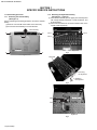
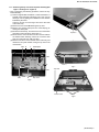
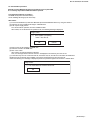
MP-XP7220KR,MP-XP5220KR
SERVICE MANUAL
Mobile mini note PC
02
2003
G1004
MP-XP7220KR,MP-XP5220KR
Area Suffix
KR ------------------
Korea
TABLE OF CONTENTS
1
SPECIFIC SERVICE INSTRUCTIONS . . . . . . . . . . . . . . . . . . . . . . . . . . . . . . . . . . . . . . . . . . . . . . . . . . . . . .
1.1
Disassembly procedure . . . . . . . . . . . . . . . . . . . . . . . . . . . . . . . . . . . . . . . . . . . . . . . . . . . . . . . . . . . .
1.2
Preinstallation procedure . . . . . . . . . . . . . . . . . . . . . . . . . . . . . . . . . . . . . . . . . . . . . . . . . . . . . . . . . . .
1.3
Caution in exchanging a bottom case . . . . . . . . . . . . . . . . . . . . . . . . . . . . . . . . . . . . . . . . . . . . . . . . .
1.4
Replace procedure of main board . . . . . . . . . . . . . . . . . . . . . . . . . . . . . . . . . . . . . . . . . . . . . . . . . . . .
1.5
Operation check item list after the repair is completed . . . . . . . . . . . . . . . . . . . . . . . . . . . . . . . . . . . .
1.6
Another sales option list . . . . . . . . . . . . . . . . . . . . . . . . . . . . . . . . . . . . . . . . . . . . . . . . . . . . . . . . . . . .
COPYRIGHT © 2003 VICTOR COMPANY OF JAPAN, LTD.
1-2
1-2
1-7
1-8
1-8
1-9
1-9
No.G1004
2003/02
MP-XP7220KR,MP-XP5220KR
SECTION 1
SPECIFIC SERVICE INSTRUCTIONS
1.1 Disassembly procedure
1.1.1 Removing the internal battery
(See Figure 1)
Prior to performing the following procedure, remove the external
battery.
(1) Remove one screw A on the bottom of the main body.
(2) Pull out the internal battery in the rear direction.
1.1.2 Removing the keyboard assembly
(See Figure 2 ~ Figure 4)
(1) Push the three latches (a) in the upper part of the keyboard
with a single-slotted screwdriver or a flat screwdriver, and
lift the keyboard.
(2) Disconnect the wires from connectors CN4 and CN1 on the
mother board respectively.
Internal battery
E
E
A
Latch a
Latch a
Latch a
Bottom
Keyboard
E
E
Fig.1
Fig.2
Keyboard
2
1 In removing
the keyboard
1
2
In attaching
the keyboard
Fig.3
Mother board
CN4
CN1
Keyboard
Fig.4
1-2 (No.G1004)
MP-XP7220KR,MP-XP5220KR
1.1.3 Removing the top case and LCD panel assembly (See
Figure 1 and Figure 5 ~ Figure 8)
• Prior to performing the following procedure, remove the keyboard assembly.
(1) Insert a single-slotted screwdriver or a flat screwdriver in a
space b on the underside of the hinge cover. Then, remove
the hinge cover by pulling the screwdriver in the direction
indicated by the arrow.
And then, remove one more hinge cover at the other side
of the main body.
(2) Remove the four screws B attaching the top case.
(3) Remove one screw C (short) and one screw D (long) attaching the shield plate.
(4) Reverse the main body, and remove the four screws E on
the bottom of the main body. (See Figure 1)
(5) Disconnect the connector wire from the connector CN2 on
the mother board. Similarly, remove the connector wires
from the connectors CN3, CN5, and CN7.
(6) Remove one latch c on the rear side of the main body, and
release the two joints d while moving the top case in the
rear direction.
CN2 B
C
Hinge cover
Space b
Fig.6
Shield plate
CN3
D
B
B
Latch c
Fig.7
CN7
CN5
B
Fig.5
Top case
Top case
Bottom case
Joint d
Fig.8
(No.G1004)1-3
MP-XP7220KR,MP-XP5220KR
1.1.4 Removing the mother board
(See Figure 9 ~ Figure 11)
• Prior to performing the following procedure, remove the keyboard assembly, the top case, and the LCD panel assembly.
(1) Remove one screw F (short), one screw G (middle), and
the two screws H (long) attaching the mother board.
(*In attaching the mother board, tighten H1, H2, G, and F
in this order.)
(2) Lift the mother board while pushing the microphone and
headphone jack in the direction indicated by the arrow, and
remove the mother board.
*Be careful not to damage the battery detector switch on
the backside of the mother board.
* In attaching the mother board, put the lever of the PCMCIA slot
through the bottom case, and then push and attach the microphone and headphone jack.
Microphone and
headphone jack
Mother board
Battery detector
switch
2
Bottom case
F
Mother board
H1
1
Fig.11
Caution
In attaching the mother board to the bottom case or in attaching the top case to the bottom case, soft workbench must not
be used because it may distort the bottom case and the top
case. Attachment operation must be performed on workbench
hard enough.
G
Fig.9
2
1
Mother board
Microphone and
headphone jack
Fig.10
1-4 (No.G1004)
H2
MP-XP7220KR,MP-XP5220KR
1.1.5 Removing the parts on the mother board
(See Figure 12 ~ 15)
• Prior to performing the following procedure, remove the mother board.
*Removing the fan assembly
(1) Remove the four screws I attaching the fan assembly.
(2) Disconnect the connector wire from the connector CN13 on
the mother board.
*Removing the hard disc drive
(1) Remove one screw J at the side of the mother board where
the hard disc drive is not attached.
(2) Remove the hard disc drive by moving the hard disc drive
in the direction indicated by the arrow.
*Removing the PCMCIA slot
(1) Remove one screw K (long) and the two screws L (short)
at the side of the mother board where the PCMCIA slot is
not attached.
(2) Hold and lift the connector side of the PCMCIA slot, and remove the PCMCIA slot.
*Removing the modem pack
(1) Remove one screw M attaching the modem pack.
(2) Pull out the socket wire connected to the modem pack.
(3) Lift the modem pack, and remove it.
PCMCIA slot
Fig.14
Fan assembly
I
CN13
Modem pack
Socket
Fig.15
Hard disc drive
PCMCIA slot
Fig.12
J
L
M
K
Socket wire
Fig.13
Modem pack
(No.G1004)1-5
MP-XP7220KR,MP-XP5220KR
1.1.6 Removing the top case and the LCD panel assembly
(See Figure 16)
• Prior to the following procedure, remove the top case and the
LCD panel assembly from the bottom case.
(1) Remove the two screws N attaching the hinge.
(2) Remove the tapes fixing the two wires of the LCD panel assembly if necessary.
N
Hinge
Tape
Tape
Hinge
Rubber pad and screw O
Latch
N
LCD
Latch
Latch
Latch
Fig.16
1.1.7 Removing the LCD panel
(See Figure 17 and Figure 18)
• Prior to the following procedure, remove the LCD panel assembly.
(1) Remove the two rubber pads (fixed to the panel with adhesive tapes) by using a sharp tool.
(2) Remove the two screws O attaching the LCD panel frame.
(3) Lift and the centers of the four sides of the LCD panel from
inside to an outward direction. (It is soft enough to be lifted.)
Then, latches in the centers of the four sides and also other
latches are removed. To remove all the latches, lift the four
sides from inside to an outward direction.
* Be careful not to damage the LCD or apply any stress to
the LCD.
(4) Remove the two screws P attaching the LCD.
(5) Remove one screw Q attaching the inverter board, and disconnect the socket wire from the connector CN2 on the inverter board.
Fig.17
LCD
P
P
Q
CN2
Inverter board
Fig.18
1-6 (No.G1004)
MP-XP7220KR,MP-XP5220KR
1.2 Preinstallation procedure
No data including Windows XP has been recorded in service parts HDD.
It is necessary to put data in HDD after HDD is replaced.
< The following materials are needed >
*CD-ROM drive (model name MP-CDX1E)
*CD for installing HD Image (a set of five CDs)
<Procedure>
(1) Connect CD-ROM drive (model name MP-CDX1E) and the Mobile Mini Note PC by using PC card slot.
(2) Insert the 1st CD for installing HD Image in CD-ROM drive.
(3) Push a power supply button.
The 1st CD starts its operation, and then installation starts.
After a while, the 1st CD finishes its operation.Then, the following message is displayed.
Image center
( ? ) Insert media 2 containing
"xxxxx" into drive Q
OK
Cancel
(4) Take out the 1st CD inside the CD-ROM drive.
(5) Insert the 2nd CD in CD-ROM drive.
(6) Click "OK" button.
After a while, the 2nd CD finishes its operation.
Then, the message "Please insert the next CD." is displayed in the same way as in the 1st CD.
(7) In the same way as in the 1st and the 2nd CD, insert each 3rd, 4th, and 5th CD in this order and install them.
(8) When the 5th CD finishes to be installed, push a power supply button and turn the power off.
* When the following error message is displayed, perform the procedure again from Procedure 1 started above.
Image center
( ? ) The media does not content correct file.
OK
(No.G1004)1-7
MP-XP7220KR,MP-XP5220KR
1.3 Caution in exchanging a bottom case
1.3.1 As for COA LABEL
Neither "LE40888-001A/COA LABEL PRO" nor "LE40888-002A/COA LABEL HOME" can be reused.
COA LABEL is also necessary in exchanging a bottom case.
1.3.2 As for serial label
"Serial label" where model name and serial number are written is not dealt with as service parts.
Please reuse it.
Please remove a label with exfoliation agent:
Parts number -- UN-001
Parts name ----- SUBSIDIALY MATERIAL
*How to remove a label
(1) Drip a few drops of exfoliation agent on an attached spatula.
(2) Immediately after (1), turn over the label from its edge with the spatula while dripping the exfoliation agent on a label by using
the spatula.
(3) If adhesive agent still remains in the surface of the bottom case, please drip a few drops of exfoliation agent on the agent and
wipe it with clean tissue paper.
1.4 Replace procedure of main board
1.4.1 Parts are put and substituted from former main board to a new main board.
* The [15-100324200 / AWARD BIOS LABEL] is pasted and substituted.
* The [13-N6K10P220 / SD DUMMY CARD] is replaced.
* The [07-016402032 / BATT-LI] is put and substituted.
* The [04-132051170 / MODEM 56K] is put and substituted.
* The [14-140522020 / WIRE CABLE FOR MDC] is put and substituted.
* The [HDD] is put and substituted.
* The [13-N6K10M122 / FAN HEAT SINC BLOCK] is put and substituted.
* The [04-001212250 / SDRAM] is put and substituted. (Only when SDRAM is installed)
* The [13-N6K10C020 / GASKET] is pasted and changes.
* The [13-N6K10L252 / COAXIAL MYLAR] is pasted and changes.
* The [13-N6K10L160 / THERMAL PAD RAM] is pasted and changes.
1.4.2 Adjust it after exchanging the substrate.
* Make the version of BIOS equal to former main board.
The version of BIOS of a new main board is 0200.
Follow it when the up-grade of BIOS is hoped to the customer.
* Set the clock of BIOS.
Because the coin type battery has not placed to the main board, the clock is not accurate.
1.4.3 Do the operation check after exchanging the substrate.
Execute the operation check following "Operation check item list after the repair is completed".
1-8 (No.G1004)
MP-XP7220KR,MP-XP5220KR
1.5 Operation check item list after the repair is completed
Item
Contents
Required equipment
1
IEEE1394
Is connected with IEEE1394 port the Digital video camera and Digital video camera made of our company.
do recognize it?
2
SD CARD
Is connected with SD card slot the SD card and do recognize it? SD card on the market.
3
PC CARD
Check whether PC card operates properly when it is connected
to PC card slot for Card Bus.
Check whether PC card operates properly when option CDROM drive is inserted in PC card slot.
4
USB
Is connected with USB the Digital video camera and do recog- Digital video camera made of our company.
nize it?
USB mouse on the market.(Transfer rate:Low)
Is connected with USB the mouse and do recognize it?
5
MIC
Is connected with the MIC terminal a MIC on the market, and is MIC on the market.
recognized it?
6
HEADPHONE Is connected with the headphone terminal a headphone on the Headphone on the market.
market, and is recognized it?
7
LAN
Do connect with the network, and do recognize it?
8
MODEM
Can the telephone line be connected, and it connect it with the Telephone line.PPP account to connect dialInternet?
up with the Internet.
9
VGA
Does it connect with the monitor, and is the image displayed? Monitor for PC
VGA Cable (Provision)
PC card corresponding to Card Bus on the
market.
(Example:100Mbase-T LAN card)
CD-ROM drive of option.
Network
10 DC in
Can AC be driven?
General power supply
11 BATTERY
Is the outer battery recognized?
Outer battery
12 LID SWITCH
Does the LID switch work?
13 RESET
Is RESET effective?
14 KEYBOARD
Is the key input effective?
15 STICK
Is the STICK effective?
16 SPEAKER
Is the sound emitted from both channels of the speaker?
17 RUNNING
Is not there trouble after it playback by using Windows media
player for continuousness eight hours?
1.6 Another sales option list
Product category
Model name
BATTERY CHARGER
MP-BCX1E
Lithium-Ion BATTERY
BN-LS12E
Lithium-Ion BATTERY
BN-LL21E
CD-ROM DRIVE
MP-CDX1E
EXTERNAL DISPLAY CABLE
MP-VGX1E
CARRYING BAG
MP-BGX2E
Note
Same as attached goods of the main body.
(No.G1004)1-9
MP-XP7220KR,MP-XP5220KR
VICTOR COMPANY OF JAPAN, LIMITED
AV & MULTIMEDIA COMPANY MOBILE IT CATEGORY 1644, Shimotsuruma, Yamato, Kanagawa 242-8514, Japan
(No.G1004)
Printed in Japan
200302WPC