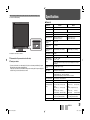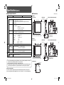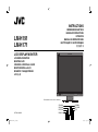
1
INSTRUCTIONS
BEDIENUNGSANLEITUNG
MANUEL D’INSTRUCTIONS
ISTRUZIONI
MANUAL DE INSTRUCCIONES
ИHCТРУKЦИЯ ПО ЭКСПЛУАТАЦИИ
使用说明书
LM-H191
LM-H171
LCD DISPLAY MONITOR
LCD-DISPLAYMONITOR
MONITEUR LCD
SCHERMO A CRISTALLI LIQUIDI
MONITOR PANTALLA LCD
МОНИТОР С ЖК-ДИСПЛЕЕМ
LCD 显示器
The illustration of the monitor is of LM-H191.
LCT2401-002A-H
LMH191&171EA_cover1.indd 1
ITALIANO
FRANÇAIS
DEUTSCH
ENGLISH
ESPAÑOL
РУССКИЙ
中文
08.7.22 5:56:56 PM
LM-H191
LM-H171
INSTRUCTIONS
LCD DISPLAY MONITOR
Table of Contents
Safety Precautions .............................................. 2
IMPORTANT SAFEGUARDS ........................... 2
Maintenance ..................................................... 3
Installation............................................................ 4
Daily Operations / Connections ......................... 6
Front panel ....................................................... 6
Rear panel ........................................................ 8
Available signals ............................................... 9
Menu Configuration—MAIN MENU .................. 10
Menu Configuration—SET UP MENU .............. 11
External Control................................................. 13
About the external control .............................. 13
Using the MAKE/TRIGGER system ............... 13
Troubleshooting................................................. 14
Specifications .................................................... 15
General ........................................................... 15
Input/output terminals ..................................... 16
Dimensions ..................................................... 16
The illustration of the monitor is of LM-H191.
ENGLISH
LMH191&171EA_EN.indd 1
08.7.8 5:40:10 PM
2
Safety Precautions
WARNING: TO REDUCE RISK OF FIRE OR ELECTRIC SHOCK, DO NOT EXPOSE THIS APPARATUS TO
RAIN OR MOISTURE. NO OBJECTS FILLED WITH LIQUIDS, SUCH AS VASES, SHALL BE
PLACED ON THE APPARATUS.
IMPORTANT SAFEGUARDS
Electrical energy can perform many useful functions. This unit has been engineered and manufactured to assure
your personal safety. But IMPROPER USE CAN RESULT IN POTENTIAL ELECTRIC SHOCK OR FIRE. In order
not to defeat the safeguards incorporated into this product, observe the following basic rules for its installation,
use, and service. Please read these “IMPORTANT SAFEGUARDS” carefully before use.
• All the safety and operating instructions should be read before the product is operated.
• The safety and operating instructions should be retained for future reference.
• All warnings on the product and in the operating instructions should be adhered to.
• All operating instructions should be followed.
The power supply voltage rating of this product is AC 120 V (For U.S.A. and Canada) and AC 220 – 240 V (For
European countries, Asian countries, and United Kingdom).
The power cord attached conforms to the following power supply voltage and countries. Use only the power
cord designated to ensure safety and EMC regulations of each country.
For European and Asian countries:
AC 220 – 240 V
For United Kingdom:
AC 220 – 240 V
This plug will fit only into a grounded power outlet. If you are unable to insert the plug into the outlet, contact
your electrician to install the proper outlet. Do not defeat the safety purpose of the grounded plug.
• This product should be operated only with the type of power source indicated on the label. If you are not
sure of the type of power supply of your home, consult your product dealer or local electric power company.
Warning:
• Do not use the same power cord for AC 120 V as for AC 220 – 240 V. Doing so may cause malfunction,
electric shock or fire.
Note for United Kingdom power cord only
The plug of United Kingdom power cord has a built-in fuse. When replacing the fuse, be sure to use only a
correctly rated approved type, re-fit the fuse cover. (Consult your dealer or qualified personnel.)
How to replace the fuse
Open the fuse compartment with the blade screwdriver, and replace the fuse.
Fuse
• Before connecting other products such as VCR’s and personal computers, you should turn off the power of
this product for protection against electric shock.
• Do not use attachments not recommended by the manufacturer as they may be hazardous.
• When replacement parts are required, be sure the service technician has used replacement parts
specified by the manufacturer or equivalents. Unauthorized substitutions may result in fire, electric shock, or
other hazards.
• Upon completion of any service or repairs to this product, ask the service technician to perform safety
checks to determine that the product is in proper operating condition.
LMH191&171EA_EN.indd 2
1.
2.
3.
a)
b)
c)
d)
e)
f)
POWER CONNECTION
For U.S.A. and Canada: AC 120 V
(not supplied)
Under the following conditions,
Turn off the power.
Unplug this product from the wall outlet.
Refer service to qualified service personnel.
When the product emits smoke or unusual smell.
When the product exhibits a distinct change in
performance—for example, no picture or no
sound.
If liquid has been spilled, or objects have fallen
on the product.
If the product has been exposed to rain or water.
If the product has been dropped or damaged in
any way.
When the power supply cord or plug is damaged.
• Do not install this product in the following places:
– in a damp or dusty room
– where the product is exposed to soot or
steam, such as near the cooking counter or a
humidifier
– near heat sources
– where condensation easily occurs, such as
near the window
• Do not place this product on an unstable cart,
stand, or table. The product may fall, causing
serious injury to a child or adult, and serious
damage to the product.
The product should be mounted according to the
manufacturer’s instructions, and should use a
mount recommended by the manufacturer.
• Do not use this product near water.
• Be sure to install the product in the place where
proper temperature and humidity are kept (☞
“Operating conditions” on page 15).
This product becomes hot during its use. Take
enough care when handling the product.
• Make enough room for inserting or removing the
power plug. Place the product as close to an AC
outlet as possible. The main power supply for the
product is controlled by inserting or removing the
power plug.
• When you install the product in a place where you
cannot easily insert or remove the power plug
from an AC outlet, insert or remove the power
cord from the AC inlet on the product.
• When the product is left unattended and unused
for a long period of time, unplug it from the wall
outlet and disconnect the cable system.
• Do not overload wall outlets, extension cords, or
convenience receptacles on other equipment as
this can result in a risk of fire or electric shock.
• Use only the accessory cord designed for this
product to prevent shock.
• Slots and openings in the cabinet are provided for
ventilation. These ensure reliable operation of the
product and protect it from overheating. These
openings must not be blocked or covered.
• Never push objects of any kind into this product
through openings as they may touch dangerous
voltage points or short-circuit the parts, which
could result in a fire or electric shock.
• Never spill liquid of any kind on the product.
• Never place anything on the product. (Placing
liquids, naked flames, cloths, paper, etc. on the
product may cause a fire.)
• Do not apply any strong shock to the LCD panel.
(Do not hit any object against it or push it with a
sharp-pointed tool.)
• Do not put heavy objects on the product.
• Do not step on or hang on the product.
Do not attempt to service this product yourself, as
opening or removing covers may expose you to
dangerous voltages and other hazards. Refer all
service to qualified service personnel.
Do not use the product for a long time if the sound
is distorted.
08.7.8 5:40:13 PM
U.S.A. only
FCC NOTICE (U.S.A. only)
CAUTION: Changes or modifications not approved
by JVC could void the user’s authority to operate the
equipment.
NOTE: This equipment has been tested and found
to comply with the limits for a Class B digital device,
pursuant to Part 15 of the FCC Rules. These limits
are designed to provide reasonable protection
against harmful interference in a residential
installation. This equipment generates, uses and can
radiate radio frequency energy and, if not installed
and used in accordance with the instructions, may
cause harmful interference to radio communications.
However, there is no guarantee that interference
will not occur in a particular installation. If this
equipment does cause harmful interference to radio
or television reception, which can be determined
by turning the equipment off and on, the user is
encouraged to try to correct the interference by one
or more of the following measures:
– Reorient or relocate the receiving antenna.
– Increase the separation between the equipment
and receiver.
– Connect the equipment into an outlet on a
circuit different from that to which the receiver is
connected.
– Consult the dealer or an experienced radio/TV
technician for help.
IMPORTANT RECYCLING INFORMATION
This product has a fluorescent lamp
that contains mercury. Disposal of
these materials may be regulated in
your community due to environmental
considerations. For disposal or recycling
information, please contact your local
authorities or for USA, the Electronic
Industries Alliance: http://www.eiae.org
European Union only
Dear Customer,
EMC Supplement
This apparatus is in conformance with the valid
European directives and standards regarding
electromagnetic compatibility and electrical safety.
European representative of Victor Company of
Japan, Limited is:
JVC Technical Services Europe GmbH
Postfach 10 05 04
61145 Friedberg
Germany
Information for Users on Disposal of Old
Equipment
Attention:
This symbol
is only valid in
the European
Union.
European Union only
[European Union]
This symbol indicates that
the electrical and electronic
equipment should not be
disposed as general household
waste at its end-of-life.
Instead, the product should be
handed over to the applicable
collection point for the recycling
of electrical and electronic
equipment for proper treatment,
recovery and recycling in
accordance with your national
legislation.
By disposing of this product
correctly, you will help to
conserve natural resources
and will help prevent potential negative effects on
the environment and human health which could
otherwise be caused by inappropriate waste
handling of this product. For more information about
collection point and recycling of this product, please
contact your local municipal office, your household
waste disposal service or the shop where you
purchased the product.
Penalties may be applicable for incorrect disposal of
this waste, in accordance with national legislation.
(Business users)
If you wish to dispose of this product, please visit
our web page www.jvc-europe.com to obtain
information about the take-back of the product.
[Other Countries outside the European Union]
If you wish to dispose of this product, please do so
in accordance with applicable national legislation or
other rules in your country for the treatment of old
electrical and electronic equipment.
This equipment is in conformity with the provisions and protection requirements of the corresponding European
Directives. This equipment is designed for professional video appliances and can be used in the following
environments:
• residential (including both of the location types class 1 and 2 found in IEC 1000-2-5)
• commercial and light industrial (including, for example, theatres)
In order to keep the best performance and ensure electromagnetic compatibility, we recommend to use cables
not exceeding the following length:
Cable
Power cord
Video signal cable
Audio signal cable
DVI cable
RGB cable
REMOTE cable
(A straight LAN cable)
(attached cable (H05VV-F 3 x 0.75 mm2))
(coaxial cable)
(shielded cable)
(shielded cable)
(shielded cable)
(twist pair cable)
Length
2.0 m
2.0 m
1.5 m
2.0 m
2.0 m
10.0 m
The inrush current of this apparatus is 9.655 ampere.
CAUTION
In case where the strong electromagnetic waves or magnetism are near the audio cable or the signal cable,
the sound or the picture will contain noise. In such cases, please keep the cable away from the sources of the
disturbance.
Maintenance
Unplug this product from the wall outlet before
cleaning.
Screen
To avoid irreparable change in appearance of the
screen such as uneven color, discoloration, scratches,
be careful about the following:
• Do not paste or stick anything using any glues or
adhesive tapes.
• Do not write anything on the screen.
• Do not strike the screen with a hard object.
• Avoid condensation on the screen.
• Do not wipe the screen with solvent such as alcohol,
thinner, or benzine.
• Do not wipe the screen forcefully.
If the screen gets stained, wipe it with a soft dry cloth,
a soft damp cloth, or a soft cloth soaked in waterdiluted neutral detergent and wrung well.
Cabinet
To avoid the deterioration or damages of the cabinet
such as its paint’s peeling away, be careful about the
following:
• Do not wipe the cabinet using solvent such as
alcohol, thinner, or benzine.
• Do not expose the cabinet to any volatile substance
such as insecticides.
• Do not allow any rubber or plastic in contact for a
long time.
• Do not wipe the cabinet forcefully.
Wipe stains off the cabinet with a soft cloth. If the
cabinet gets heavily stained, wipe it with a soft cloth
soaked in water-diluted neutral detergent and wrung
well, then wipe with a soft dry cloth.
Ventilation openings
Use a vacuum cleaner to get rid of the dust around the
intakes (all the openings). If a vacuum cleaner is not
available, use a cloth and wipe it off. Leaving the dust
around the intakes may prevent proper temperature
control and cause damage to the product.
ENGLISH
LMH191&171EA_EN.indd 3
3
08.7.8 5:40:15 PM
4
Installation
CAUTION
To detach the stand
• Do not rest your arm on the monitor or lean against the monitor.
• Do not touch the LCD panel when installing the monitor.
• Make sure to install the monitor securely to prevent the monitor from falling over, which causes damage to the
monitor or injury.
CAUTION
Lay the monitor on a cloth with the LCD panel facing down to prevent the LCD panel from being damaged.
Attachment screws
You can tilt the monitor as follows:
• When the monitor is not tilted (0°),
the guidelines align as illustrated.
Screw holes for
stand attachment
Guidelines
About 20°
0°
About 8°
The illustration of the monitor is of LM-H191.
CAUTION
• Be careful not to pinch your fingers in the gap between the
monitor and the stand.
• When the stand plate is attached to the lower position of the
stand body (☞ “To adjust the stand height” on page 5), you
cannot tilt the monitor downward.
The illustration of the monitor is of LM-H191.
You can lift the stand up and place the monitor as illustrated below.
About 144°
CAUTION
Remove the
screw.
Lift the stand
up and align
the guidelines.
Guidelines for 144°
Attach the
removed screw.
• When lifting up the stand, lay the
monitor on a cloth with the LCD panel
facing down to prevent the LCD panel
from being damaged.
• Be careful not to pinch your fingers in
the moving parts.
• When lifting up the stand, make
sure to align the guidelines for 144°
and fasten the screw; otherwise the
monitor may fall over.
• Place the monitor on a mat to avoid
scratching the table surface.
• Do not lift up the stand when the
stand plate is attached to the lower
position of the stand body (☞ “To
adjust the stand height” on page 5).
When installing the stand to the monitor, insert the guides of the stand plate into the
guide holes on the monitor to place the stand on the correct position. Then fix the
stand firmly with the attachment screws.
Guide holes
Guides
Monitor
Screw holes for stand attachment
(on the monitor)
Stand plate
Screw holes for stand
attachment (on the stand)
The illustration of the monitor is of LM-H191.
LMH191&171EA_EN.indd 4
08.7.8 5:40:17 PM
To adjust the stand height
To prevent an accidental fall
To change the stand height, change the position of the stand plate as illustrated below after
detaching the stand from the monitor.
• For detaching the stand, see “To detach the stand” on page 4.
Fix the monitor to a wall by using strings.
<Higher position>
Stand plate
<Lower position>
Screw holes for higher
position
Fixing the monitor
Attach the hook (not provided) to the VESA mounting holes on the rear panel using M4 x 10 mm
screws (not provided). Bind the hooks on the rear panel of the monitor to a wall or a pillar using
durable string.
Screw holes for lower
position
Stand plate
The illustration of the monitor
is of LM-H191.
Hook and screws (M4 x 10 mm)
(not provided)
Hook (not provided)
ENGLISH
LMH191&171EA_EN.indd 5
5
08.7.8 5:40:18 PM
6
Daily Operations / Connections
7 Front panel
• “NO EFFECT” is displayed when you press a button which is not available for the current input or signal format (the lamp lights even when the
function does not actually work).
• The items controlled by the MAKE system cannot be controlled by the buttons on the front panel (“REMOTE ON” is displayed and the lamps
do not light).
1
2
3
4
5
6
7
8
9
p
The illustration of the monitor is of LM-H191.
1 Speaker (monaural)
The speaker emits the audio signal for the
selected input.
2 CHROMA/PHASE ( ) button*1
Displays the adjustment bar for the picture
color density or hue.
• Each time you press the button, the
adjustment for chroma and phase changes.
• To adjust, press or (4) button.
• The adjustment is memorized for each
Picture Mode (7).
3 CONTRAST/BRIGHT ( ) button*1
Displays the adjustment bar for the picture
contrast or brightness.
• Each time you press the button, the
adjustment for contrast and brightness
changes.
• To adjust, press or (4) button.
• The adjustment is memorized for each
Picture Mode (7).
LMH191&171EA_EN.indd 6
4 VOLUME –/+ (
/ ) buttons*2
Adjusts the volume.
5 MENU button
Displays the MAIN MENU.
• To display the SET UP MENU, press
button while pressing MENU button.
• For the menu operations, see page 7.
6 SCAN SIZE button/lamp
Selects the screen size when VIDEO 1 or
VIDEO 2 is selected for the input.
• Each time you press the button, the screen
size changes as follows:
• When “NARROW” is selected, the lamp
lights.
• When “NARROW” is selected, black bars
appear on the top and the bottom of the
screen because the aspect ratio of the LCD
panel is 5:4.
• This setting is not available for signals from
a computer is selected for the input.
7 PICTURE MODE button/lamp
Selects the Picture Mode.*3
STD.: Normal picture
DARK ENHANCED: Makes the dark parts of
the picture clear.
VIVID: Makes the picture vivid.
DYNAMIC: Makes the picture bright.
• When “DARK ENHANCED, “VIVID,” or
“DYNAMIC” is selected, the lamp lights.
• When RGB or DVI is selected for the input,
the Picture Mode is fixed to “STD.”
• When “DYNAMIC” is selected, high
luminance parts of pictures may not be
displayed properly. In this case, select
another Picture Mode.
8 INPUT SELECT buttons/lamps
Selects an input.
VIDEO 1: VIDEO 1 IN or Y/C terminal
VIDEO 2: VIDEO 2 IN terminal
RGB: RGB terminal*4
DVI: DVI-D terminal
• The lamp for the selected input lights.
9 Power lamp
Unlit: The monitor is completely off (the AC
plug is not connected).
Lights in Green: The monitor is on or in the
Gray Back mode (☞ “NO SYNC ACTION” in
“SYNC FUNCTION” on page 12).
Lights in orange: The monitor is off (on
standby).
Flashes in orange: The monitor is in the
Power Save mode (☞ “NO SYNC ACTION” in
“SYNC FUNCTION” on page 12).
p
button
Turns on and off (on standby) the monitor.
*1 When a menu screen or adjustment bar is displayed,
these buttons work as / to select an item.
*2 When a menu screen or adjustment bar is displayed,
these buttons work as / to adjust the item or
select an option.
*3 To reset the adjustments for each Picture Mode, see
“Resetting the Picture Mode” (☞ page 7).
*4 Before using this input, perform “AUTO ADJUST” (☞
“AUTO ADJUST” on page 10).
08.7.8 5:40:19 PM
Resetting the Picture Mode
Main Menu Operations
Setup Menu Operations
You can reset the following picture
adjustments you have made for each Picture
Mode.
• Adjustments by the buttons on the front
panel
• “SHARPNESS,” “CTI.,” and “LTI.” in the
MAIN MENU (☞ page 10)
1 Press MENU button.
1 Press
Selected item
button while pressing
MENU button.
Selected item
1 Press PICTURE MODE button
repeatedly to select the mode you
want to reset.
2 Press and hold PICTURE MODE
button.
Operation guide
The confirmation message appears.
2 Press
buttons to select an item,
then press
buttons to make
adjustments.
Operation guide
2 Press
buttons to select an item,
then press .
• For some items, adjustments will be
made by pressing
.
Selected Picture Mode
3 Press PICTURE MODE button.
Ex.: When “COLOR SYSTEM” is selected
3 Press MENU button to finish the
menu operation.
Ex.: When “REMOTE SETTING” is selected
3 Press
buttons to select an item,
then press
buttons to make
adjustments.
4 Press MENU button to return to the
previous menu.
• Pressing the button again finishes the
menu operation.
ENGLISH
LMH191&171EA_EN.indd 7
7
08.7.8 5:40:21 PM
8
Daily Operations / Connections (cont.)
7 Rear panel
Note for connections
2
3
4
• Before making any connections, turn off all the
equipment.
• Use a cord whose plugs correctly match the
terminals on this monitor and the equipment.
• Plugs should be firmly inserted; poor
connections could cause noise.
• When unplugging a cord, be sure to grasp its
plug and pull it out.
• DO NOT connect the power cord until all
connections are completed.
• Refer also to the user manual of each piece of
equipment.
1 AC IN terminal
1
5
6
Security slot
Install a security wire to this slot.
7
The illustration of the monitor is of LM-H191.
AC power input connector.
• Connect the provided AC power cord to an
AC outlet.
2 REMOTE terminal (MAKE/TRIGGER)
Terminal for controlling the monitor by an
external control.
☞ “External Control” on page 13
3 RGB terminals
Input terminal for the analog RGB signals.
• Use the AUDIO INPUT RGB terminal (7)
for audio connection.
4 DVI-D terminal
Input terminal for the DVI-D signal from a
personal computer.
• Use the AUDIO INPUT DVI-D terminal (7)
for audio connection.
5 VIDEO 2 IN/OUT terminals
Input (IN) and output (OUT) terminals for the
composite signals.
• Use the AUDIO INPUT VIDEO 2 terminal
(7) for audio connection.
6 VIDEO 1 IN/OUT, Y/C terminals
Input (IN) and output (OUT) terminals for the
composite signals and input terminal for Svideo signals (Y/C).
• When both the IN and Y/C terminals are
used, signals to the Y/C terminal have
priority.
• Use the AUDIO INPUT VIDEO 1 terminal
(7) for audio connection.
7 AUDIO INPUT VIDEO 1/VIDEO 2/RGB/DVI-D
terminals
Input terminals for the analog audio signals.
• Use the video terminal with the same name
for video connection.
Attaching the Ferrite Core
Attach the ferrite core to the power cord.
• Using the power cord without the ferrite core may lead to noise (interference).
1
Open the ferrite core, insert the power cord
and close the ferrite core.
2
Attach the ferrite core to the AC IN end of
the power cord.
Ferrite core
Power cord
To the AC IN
terminal
LMH191&171EA_EN.indd 8
08.7.8 5:40:22 PM
7 Available signals
Frequency
Signal type
Horizontal (kHz)
Vertical (Hz)
NTSC (3.58)
15.734
(60/)59.94
BW/60
PAL
15.734
15.625
(60/)59.94
50
BW/50
480/60p
576/50p
VGA
VGA_TEXT
SVGA
15.625
31.5/31.469
31.25
31.47
31.47
35.15
37.879
48.363
56.476
47.396
63.981
50
60/50.94
50
59.94
70.08
56.25
60.317
60.004
70.069
59.99
60.02
XGA
WXGA
SXGA
Status display*
Specification of the Y/C terminal
NTSC
NTSC (Y/C)
BW60
PAL
PAL (Y/C)
BW50
640x480 60Hz
640x576 50Hz
640x480 60Hz
720x400 70Hz
800x600 56Hz
800x600 60Hz
1024x768 60Hz
1024x768 70Hz
1280x768 60Hz
1280x1024 60Hz
Input signal
GND (Y)
GND (C)
Y
C
DVI-D
√
√
–
–
√
√
–
–
√
√
–
–
√
√
–
–
–
–
–
–
–
–
–
–
–
–
–
–
–
–
–
–
–
–
–
√
√
√
√
√
√
√
√
√
√
–
–
–
√
Specification of the RGB terminal
Connect it to the S-video output
terminal.
Pin No.
1
2
3
4
VIDEO 1
IN / Y/C
Input terminal
VIDEO
RGB
2 IN
–
–
√
√
6
7
8
Input signal
Red
Green
Blue
–
GND
GND
GND
GND
Pin No.
9
10
11
12
13
Input signal
+5 V
GND
GND
DDC Data
Horizontal/
composite sync
14
Vertical sync
15
DDC Clock
External GND
• Some signals may not be displayed normally even if its frequency is within
the acceptable range (☞ “Horizontal/vertical frequency (computer signal)” on
page 15).
• When WXGA is displayed, black bars appear on the top and the bottom of the
screen.
* About the Status Display
When “STATUS DISPLAY” (☞ page 12) is set to “AUTO,” the status is displayed for
about 3 seconds in the following cases:
– When you press the INPUT SELECT button of the current input
– When you change the input
– When the signal condition of the current input changes
– When you turn on the monitor
• “NO SYNC” is displayed when no video signal comes in.
• “Out of range” is displayed for a noncompliant video signal input.
–
√
√
Specification of the DVI-D terminal
Connect it to the analog RGB output
terminal (D-sub 15-pin) on a personal
computer.
Pin No.
1
2
3
4
5
√: Acceptable
—: Not acceptable
Connect it to the DVI-D output terminal on a personal computer.
Pin No.
1
2
3
4
5
6
7
8
Input signal
T.M.D.S Data 2–
T.M.D.S Data 2+
T.M.D.S Data 2 shield
NC
NC
DDC Clock
DDC Data
NC
Pin No.
9
10
11
12
13
14
15
16
Input signal
T.M.D.S Data 1–
T.M.D.S Data 1+
T.M.D.S Data 1 shield
NC
NC
+5 V Power
GND
Hot Plug Detect
Pin No.
17
18
19
20
21
22
23
24
ENGLISH
LMH191&171EA_EN.indd 9
Input signal
T.M.D.S Data 0–
T.M.D.S Data 0+
T.M.D.S Data 0 shield
NC
NC
T.M.D.S Clock shield
T.M.D.S Clock+
T.M.D.S Clock–
9
08.7.8 5:40:22 PM
10
Menu Configuration—MAIN MENU
BACK LIGHT
For the operation procedure, see page 7.
Setting value: 00 – 25
Adjusts the brightness of the display.
When VIDEO 1 or VIDEO 2 is selected for the input:
SHARPNESS*1, 2
Selected Picture Mode
Select by pressing PICTURE MODE on the front
panel (☞ 7 on page 6). (Not displayed when “STD.” is
selected.)
Setting value: 00 – 10
Adjusts the sharpness of the picture.
CTI.*1, 2 Setting value: OFF, NORMAL, HARD
Adjusts the clearness of the outlines of the chrominance signal.
• This setting does not affect BW signals.
LTI.*1, 2
Setting value: OFF, NORMAL, HARD
Adjusts the clearness of the outlines of the luminance signal.
Operation guide
Shows the buttons for each operation.
COLOR SYSTEM*1
Setting value: AUTO, NTSC, PAL
Selects the color system.
• If the picture is unstable with “AUTO,” select “NTSC” or “PAL.”
ASPECT*1
Setting value: 4:3, 16:9
Selects the aspect ratio.
When RGB is selected for the input:
sub menu POSI.
Setting value: LOWER, UPPER
Selects the position of the picture adjustment bar and volume adjustment bar.
Press
to perform “AUTO ADJUST.”
Operation guide
Shows the buttons for each operation.
Adjusts pictures of analog RGB signals automatically. Perform this adjustment when you input analog
RGB signals for the first time.
• Pictures may not be adjusted properly when you perform “AUTO ADJUST” with a picture of texts or
images on a black background. Perform “AUTO ADJUST” when an image is displayed fully on the
screen.
• After performing “AUTO ADJUST,” you can adjust each item manually.
Item
H.SIZE*4
H.POSI.*4
V.SIZE*4
V.POSI.*4
DOT CLOCK*4
CLOCK
PHASE*4
When DVI is selected for the input:
Operation guide
Shows the buttons for each operation.
• The menu automatically disappears in about 30 seconds after the previous operation.
• Some items may not appear on the menu depending on the input or the input signal.
• The items controlled by the MAKE system do not appear on the menu.
LMH191&171EA_EN.indd 10
AUTO ADJUST*3
To do
Adjust the horizontal picture size.
Adjust the horizontal picture position.
Adjust the vertical picture size.
Adjust the vertical picture position.
Eliminates stripes or flickering by adjusting the both
settings.
Setting value
–10 – 00 – +10
000 – 100
–10 – 00 – +10
000 – 082*5
000 – 100
000 – 063
*1 Displayed only when VIDEO 1 or VIDEO 2 is selected for the input.
*2 Memorized for each Picture Mode (☞ “ 7 PICTURE MODE button/lamp” on page 6).
*3 Displayed only when RGB is selected for the input.
*4 Memorized for each signal format. For some signals, the adjustment may not take effect.
*5 The maximum value is different depending on the incoming signal format (“082” is an example for SXGA
signals).
08.7.8 5:40:24 PM
Menu Configuration—SET UP MENU
PICTURE SUB ADJ.
For the operation procedure, see page 7.
Adjusts the standard level for the picture adjustment.
Item
CONTRAST*1
BRIGHT*1
CHROMA*1, 2
PHASE*1, 2
sub menu
reset
To do
Setting value
Adjust the standard level for the contrast adjusted with
CONTRAST button on the front panel.
Adjust the standard level for the brightness adjusted
with BRIGHT button on the front panel.
–40 – +40
Adjust the standard level for the chroma adjusted with
CHROMA button on the front panel.
Adjust the standard level for the phase adjusted with
PHASE button on the front panel.
Display the adjustment bar for each item of “PICTURE SUB ADJ.”
Select an item by pressing
, then adjust the picture while viewing the actual picture.
Restore the default settings for all the items in “PICTURE SUB ADJ.” regardless of the
adjustments for the Picture Mode (☞ “ 7 PICTURE MODE button/lamp“ on page 6).
WHITE BALANCE SET.
Operation guide
Shows the buttons for each operation.
Selects the color temperature and adjusts the drive level of each color (R/G/B).
Item
COLOR TEMP.
R DRIVE, G DRIVE,
B DRIVE*3
sub menu
reset
Selected screen size
Select by pressing SCAN SIZE on the front
panel (☞ 6 on page 6).
• The menu automatically disappears in about 30 seconds after the previous operation.
• Some items may not appear on the menu depending on the input or the input signal.
• The items controlled by the MAKE system do not appear on the menu.
To do
Select the color temperature.
Adjust the drive level of each color (red, green, and
blue).
Setting value
HIGH, LOW, USER
–20 – +20 (–255 – 255 when
“USER” is selected for “COLOR
TEMP.”)
Display the adjustment bar for each item of “WHITE BALANCE SET.”
Select an item by pressing
, then adjust the picture while viewing the actual picture.
Restore the default settings for all the items in “WHITE BALANCE SET.”
SIZE/POSI. ADJ.*2
Adjusts the size and position of the picture.
• When RGB is selected for the input, perform “AUTO ADJUST” (☞ page 10).
Item
H.SIZE*4
H.POSI.*4
V.SIZE*4
V.POSI.*4
reset
To do
Setting value
Adjust the horizontal picture size.
–5 – +10 – +20
Adjust the horizontal picture position.
–20 – 00 – +20
Adjust the vertical picture size.
–10 – +5 – +15
Adjust the vertical picture position.
–20 – 00 – +20
Restore the default settings for all the items in “SIZE/POSI. ADJ.”
*1 Memorized for each input.
*2 Displayed only when VIDEO 1 or VIDEO 2 is selected for the input.
*3 Memorized for each input. Also, memorized for each color temperature setting.
*4 Memorized for each input. Also, memorized for each SCAN SIZE setting.
ENGLISH
LMH191&171EA_EN.indd 11
11
08.7.8 5:40:26 PM
12
Menu Configuration—SET UP MENU (cont.)
SYNC FUNCTION
Setting for the synchronization with signals
Item
SYNC TYPE
NO SYNC ACTION
To do
Select the sync signal for RGB input.
Select the screen status when no signal is
coming in.
Select the period until the screen status
changes as selected in “NO SYNC ACTION”
after signals stop coming in.
DELAY TIME
Setting value
H/V. SYNC, C.SYNC, G.ON SYNC
OFF, POWER SAVE (Power Save mode),
GRAY BACK (Gray Back mode)
30 sec., 5 min., 15 min.
• The C.SYNC input level is TTL (☞ page 16).
STATUS DISPLAY
Setting value: AUTO, OFF
☞ “About the Status Display” on page 9
Operation guide
Shows the buttons for each operation.
CONTROL LOCK
Setting value: OFF, ON
Turns on (or off) the control lock function to disable the buttons on the front panel.
• The following operations are available even when this function is activated.
– Turning on/off (on standby) the monitor
– Displaying the SET UP MENU (by pressing button while pressing MENU button) and turning
“CONTROL LOCK” to “OFF”
– Operating the monitor by an external control
If you try other operations, “Control lock on!” appears on the screen.
all reset
• The menu automatically disappears in about 30 seconds after the previous operation.
• Some items may not appear on the menu depending on the input or the input signal.
• The items controlled by the MAKE system do not appear on the menu.
REMOTE SETTING
Setting for the external control (☞ “External Control” on page 13)
Item
SYSTEM
PORT F1 – PORT
F6
To do
Select the external control method for the MAKE/
TRIGGER terminal.
Assign the control functions to the pins of the
MAKE/TRIGGER terminal.
• You cannot change the functions assigned for
“PORT F7” and “PORT F8.”
Setting value
MAKE, TRIGGER
Restores all the settings and adjustments of the monitor to the default.
• “HOUR METER X100h” will not be reset.
HOUR METER X100h
Displays the total hours of use. This item is used for maintenance of the monitor.
• The hour is shown in 100-hour unit.
• The hour will not be reset.
• The hour is reset to “000” after the total hours of use have reached to “999.”
• Use time less than 1 minute is not accumulated.
VIDEO 1, VIDEO 2, RGB, DVI,
STD., DARK ENHANCED, VIVID,
DYNAMIC, AUTO ADJ., SCAN SIZE,
ASPECT, STAND BY/ON, – – – (no
function)
• “STAND BY/ON” is not available when “SYSTEM” is “MAKE.”
LMH191&171EA_EN.indd 12
08.7.8 5:40:27 PM
External Control
7 About the external control
This monitor has the MAKE/TRIGGER terminal, which allows you to control the monitor by the make
contact or the trigger system.
• MAKE (make contact) system: Controls the monitor by short-circuiting the corresponding pin
terminal to the GND pin terminal, or disconnecting (opening) it.
• TRIGGER (trigger) system: Controls the monitor by sending the pulse signal instantaneously to
the corresponding pin terminal.
To assign the functions to the pin terminals
For the operation procedure, see page 7.
1 Select “REMOTE SETTING” on the SET UP MENU.
2 Select a pin name (“PORT F1” – “PORT F6”) for which you want to assign a function, then select
the function you want to assign.
• For selectable functions, see the tables below.
Display
Control priority is as follows.
MAKE > TRIGGER/buttons and menu on the monitor
• You can use the external control even when “CONTROL LOCK” is set to “ON” (☞ page 12).
7 Using the MAKE/TRIGGER system
The MAKE/TRIGGER terminal is configured as follows. You can assign a function to each pin
terminal in “REMOTE SETTING” (☞ “PORT F1” – “PORT F6” on page 12).
• You cannot change the functions assigned to the pin terminals from 7th and 8th.
This is a female terminal.
Pin No.
1
2
3
4
Pin name
PORT F1
PORT F2
PORT F3
PORT F4
Pin No.
5
6
7
8
Pin name
PORT F5
PORT F6
ENABLE*1
GND
Functions to be controlled
Opening
Short-circuiting
VIDEO 1
Changes the input to “VIDEO 1.”
Invalid
Valid
VIDEO 2
Changes the input to “VIDEO 2.”
Invalid
Valid
RGB
Changes the input to “RGB.”
Invalid
Valid
DVI
Changes the input to “DVI.”
Invalid
Valid
STD.
Changes the Picture Mode to “STD.”
Invalid
Valid
DARK
ENHANCED
Changes the Picture Mode to “DARK
ENHANCED.”
Invalid
Valid
VIVID
Changes the Picture Mode to “VIVID.”
Invalid
Valid
DYNAMIC
Changes the Picture Mode to “DYNAMIC.”
Invalid
Valid
AUTO ADJ.
Adjusts the size/position of the picture.
Invalid
Valid
SCAN SIZE
Selects the screen size.
OVER
NARROW
ASPECT
Changes the aspect ratio.
4:3
STAND BY/ON*2
Turns on/off (on standby) the power.
☞ page 6 “p
–––
No function
16:9
–
button”
–
*
*1 The 7th pin terminal makes the external control valid/
invalid. Make sure to control the terminal by the MAKE
system.
• You cannot assign the same function to different pin terminals.
• The TRIGGER system switches each function by short-circuiting the pin terminal for about 1
second and opening it.
*2 Must be controlled with the TRIGGER system.
Operation
1 Select the control method (“SYSTEM”) in “REMOTE SETTING.”
2 Short-circuit the 7th pin terminal (ENABLE) to the 8th pin terminal (GND) so that the monitor can
be controlled by the external control.
3 When selecting “MAKE”: Operate each function by short-circuiting the corresponding pin
terminal to the 8th pin terminal (GND) or opening it.
When selecting “TRIGGER”: Operate each function by pulse control, that is short-circuiting the
corresponding pin terminal to the 8th pin terminal (GND) for about 1 second and opening it.
• When changing the input or Picture Mode with the MAKE system, only one pin terminal must be
short-circuited. (Other pin terminals must be opened.)
• When selecting the TRIGGER system, you can operate only one function at a time. Operate the
functions one by one.
ENGLISH
LMH191&171EA_EN.indd 13
13
08.7.8 5:40:28 PM
14
Troubleshooting
Solutions to common problems related to the monitor are described here. If none of the solutions
presented here solves the problem, unplug the monitor and consult an authorized dealer or service
center.
Symptom
Probable cause and corrective action
Page
No power supply
• Firmly insert the AC power plug.
8
No picture with the
power on
• Select the correct input with INPUT SELECT buttons.
• Connect the signal cable firmly.
• Turn on the power of the connected component and set the output
correctly.
• Check if the input signal format is acceptable on the monitor.
6
8
—
• Adjust the volume level.
• Connect the signal cable firmly.
• Turn on the power of the connected component and set the output
correctly.
6
8
—
No sound
9
“OTHERS” or “Out
of range” appears.
• Check if the input signal format is acceptable on the monitor.
8, 9
“NO SYNC”
appears.
• Select the correct input with INPUT SELECT buttons.
• Connect the signal cable firmly.
• Select the correct sync signal (“SYNC TYPE”) of “SYNC FUNCTION”
in the SET UP MENU.
• Turn on the power of the connected component and output video
signals. Or, check if the video output of the component (video output
setting of the VCR or graphic board of the computer) is set correctly.
6
8
12
6, 11
Wrong color, no
color
• Adjust the picture using the adjustment buttons on the front panel or
adjust the items of “PICTURE SUB ADJ.” in the SET UP MENU. Or,
perform “reset” in “PICTURE SUB ADJ.”
• Select the proper color system (“COLOR SYSTEM”) in the MAIN
MENU.
• Adjust the items of “WHITE BALANCE SET.” in the SET UP MENU.
Or, perform “reset” in “WHITE BALANCE SET.”
• Adjust the contrast using the adjustment buttons on the front panel
or adjust the “CONTRAST” of “PICTURE SUB ADJ.” in the SET UP
MENU.
• If the Picture Mode is “DYNAMIC,” select another one.
6, 11
High luminance
parts of pictures
are not displayed
properly.
—
Symptom
The picture
becomes blurred.
Wrong picture
position, wrong
picture size.
Probable cause and corrective action
Page
• Adjust the picture contrast or brightness by using the adjustment
buttons on the front panel. Or, adjust “CONTRAST” or “BRIGHT” of
“PICTURE SUB ADJ.” in the SET UP MENU.
6, 11
•
•
•
•
6
9
10
10, 11
Check if the setting of SCAN SIZE is appropriate.
Check if the input signal format is acceptable on the monitor.
Check if the setting of aspect ratio is appropriate.
Adjust the picture size (H.SIZE/V.SIZE) or position (H.POSI./V.POSI.)
of “SIZE/POSI. ADJ.” in the SET UP MENU. When you input analog
RGB signals, perform “AUTO ADJUST” first.
• For some signals, the picture cannot be displayed fully in the effective
screen area. There is no sure method to solve this problem.
Some items do not
appear on the menu.
• The items which are not available for the current input or the current
input signal are not displayed on the menu. Change the input or the
input signal.
• The items controlled by the MAKE system are not displayed on the
menu.
Buttons on the
monitor do not
work.
• Set “CONTROL LOCK” in the SET UP MENU to “OFF.”
• You cannot use the buttons for the items controlled by the MAKE
system. Disable the external control.
—
—
13
12
13
10
11
6
The following are not malfunctions.
• When a still image is displayed for a long time, it may remain indistinctly on the screen after the picture has
changed. Though the remaining picture will disappear after a while, there may be a case that it remains
for a long period depending on the length of time the still image was displayed for. This is due to the
characteristics of the LCD display and is not a malfunction.
• The red spots, blue spots and green spots on the panel surface are a normal characteristic of LCD displays,
and not a problem. The LCD display is built with very high precision technology; however, be aware that a
few pixels may be missing or constantly lit.
• The following symptoms are problems only when pictures or sounds are not played back normally.
– A slight electric shock occurs when you touch the monitor.
– The top and/or rear panel of the monitor becomes hot.
– The monitor emits a cracking noise.
– The monitor emits a mechanical noise.
LMH191&171EA_EN.indd 14
08.7.8 5:40:30 PM
When the screen goes blank, and the power lamp on the front panel starts flashing in red...
The monitor is malfunctioning.
Specifications
7 General
Model name
The illustration of the monitor is of LM-H191.
1
2
Disconnect the AC power cord from the AC outlet.
Contact your dealer.
• If you turn on the monitor soon after turning it off (or after a short-term power failure), the power
lamp may flash and no image may be displayed.
In this case, wait at least 10 seconds before turning on the monitor again. If the power lamp does
not flash in red, you can use the monitor as normal.
LM-H191
Type
LCD Display Monitor
Screen size
Type 19 format
Aspect ratio
5:4
LM-H171
Type 17 format
LCD panel
19˝, active matrix TFT
17˝, active matrix TFT
Effective screen size
Width: 376.3 mm (14 13/16˝)
Height: 301 mm (11 13/16˝)
Width: 337.9 mm (13 7/16˝)
Height: 270.3 mm (10 3/4˝)
Number of pixels
displayed
1 280 x 1 024
Number of colors
displayed
16.77 million
Viewing angle (TYP.)
(CR > 10)
178° (Horizontally), 178° (Vertically)
160° (Horizontally), 160° (Vertically)
Panel brightness (TYP.) 300 cd/m2
Contrast ratio (TYP.)
1300:1
1000:1
Horizontal/vertical
frequency (computer
signal)
H: 31.5 kHz – 65 kHz
V: 56 Hz – 75 Hz
Compliant video signal
format
☞ “Available signals” on page 9
Audio output
Internal speaker: 0.8 W (monaural)
Operating conditions
Operating temperature: 0°C – 40°C (32°F – 104°F)
Operating humidity: 20% – 80% (non-condensing)
* Slightly variable depending on ambient conditions for installation.
Power requirements
AC 120 V/AC 220 – 240 V, 50 Hz/60 Hz
Rated current
0.9 A (AC 120 V)/0.7 A (AC 220 – 240 V) 0.7 A (AC 120 V)/0.5 A (AC 220 – 240 V)
External dimensions
(excluding protruding
parts)
Width:
413 mm (16 3/8˝)
Height:
404.8 mm (16˝)
Depth:
199 mm (7 7/8˝)
(with the stand)
* Some signals within this frequency range may not be displayed (“Out of range” is
displayed).
413 mm (16 3/8˝)
364 mm (14 3/8˝)
74 mm (3˝)
(without the stand)
Weight
8.2 kg (18.0 lbs) (with the stand)
6.4 kg (14.1 lbs) (without the stand)
Accessories
AC power cord x 2, Ferrite core x 1
Width:
374 mm (14 3/4˝)
374 mm (14 3/4˝)
Height:
374.8 mm (14 7/8˝) 334 mm (13 1/4˝)
Depth:
199 mm (7 7/8˝)
74 mm (3˝)
(with the stand)
(without the stand)
7.5 kg (16.5 lbs) (with the stand)
5.8 kg (12.8 lbs) (without the stand)
ENGLISH
LMH191&171EA_EN.indd 15
15
08.7.8 5:40:31 PM
16
Specifications (cont.)
LM-H191
LM-H171
Video
<Side view>
29 (1 1/4)
VIDEO 1 Y/C
Input of Y/C signal:
Y/C connector x 1
Y:
1 V(p-p), 75 Ω
C:
0.286 V(p-p), 75 Ω (for NTSC)
0.3 V(p-p), 75 Ω (for PAL)
DVI-D
DVI-D signal input:
DVI-D connector x 1 (compatible with DDC2B)
RGB
Input of analog RGB signal: D-sub 15-pin x 1
G:
1 V(p-p), 75 Ω
G. on sync:
0.3 V(p-p)
B, R:
0.7 V(p-p), 75 Ω
H. sync:
TTL
V. sync:
TTL
C. sync:
TTL
TTL:
LOW:
0 V – 0.8 V
HIGH:
2.5 V – 5 V
100 (4)
1.5 (1/16)
46
(1 7/8)
*1 369.5 mm (15 1/8˝) at the lower position
199 (7 7/8)
LM-H171
<Front view>
<Side view>
30.2 (1 1/4)
VESA mounting holes
(4-M4, depth: 10 mm)
<Rear view (without the stand)>
74 (3)
100 (4)
374 (14 3/4)
Audio
External control
☞ “External Control” on page 13
46
(1 7/8)
*2 339.5 mm (13 3/8˝) at the lower position
Notice on transportation
This monitor is precision equipment and needs dedicated packing material for transportation.
Never use any packing material supplied from sources other than JVC or JVC-authorized dealers.
VESA mounting holes
(4-M4, depth: 10 mm)
Stand bottom
104 (4 1/8)
199 (7 7/8)
• For easy understanding, pictures and illustrations are shown by being emphasized, omitted or
composed, and may be slightly different from actual products.
• Design and specifications are subject to change without notice.
• All company names and product names mentioned herein are used for identification purposes
only, and may be the trademarks or registered trademarks of their respective companies.
199 (7 7/8)
187 (7 3/8)
Analog audio signal input:
1 line, stereo mini jack,
500 mV (rms), high impedance
100 (4)
AUDIO INPUT
(RGB, DVI-D)
334 (13 1/4)
Analog audio signal input:
1 line, RCA connector,
500 mV (rms), high impedance
374.8 (14 7/8)*2
1.5 (1/16)
AUDIO INPUT
(VIDEO 1, VIDEO
2)
LMH191&171EA_EN.indd 16
74 (3)
413 (16 3/8)
100 (4)
Input/output of composite signal:
1 line, BNC connector x 2, 1 V(p-p), 75 Ω
* The input (IN) and output (OUT) terminals are bridge-connected (auto
termination).
<Rear view (without the stand)>
364 (14 3/8)
VIDEO 1 IN/OUT
VIDEO 2 IN/OUT
REMOTE (MAKE/
TRIGGER)
Unit: mm (inch)
LM-H191
<Front view>
404.8 (16)*1
Model name
7 Dimensions
187 (7 3/8)
7 Input/output terminals
240 (9 1/2)
08.7.23 9:15:49 AM
LM-H191/LM-H171 LCD DISPLAY MONITOR
© 2008 Victor Company of Japan, Limited
LM-H191&171EA_Cover.indb 4
0708STH-MW-MT
08.7.10 9:37:51 AM