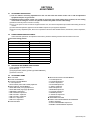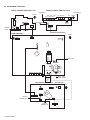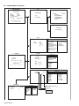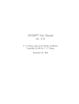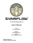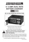
1
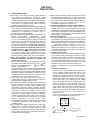
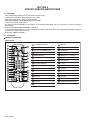
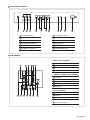
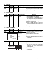
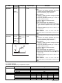
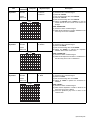
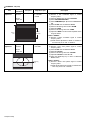
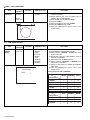
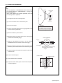
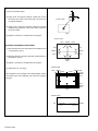
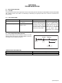
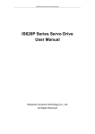
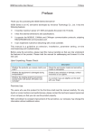
SERVICE MANUAL FLAT COLOUR TELEVISION 9 2004 YA139 AV-29V514/B BASIC CHASSIS CW TABLE OF CONTENTS 1 2 3 4 5 PRECAUTION. . . . . . . . . . . . . . . . . . . . . . . . . . . . . . . . . . . . . . . . . . . . . . . . . . . . . . . . . . . . . . . . . . . . . . . . . 1-3 SPECIFIC SERVICE INSTRUCTIONS . . . . . . . . . . . . . . . . . . . . . . . . . . . . . . . . . . . . . . . . . . . . . . . . . . . . . . 1-4 DISASSEMBLY . . . . . . . . . . . . . . . . . . . . . . . . . . . . . . . . . . . . . . . . . . . . . . . . . . . . . . . . . . . . . . . . . . . . . . . 1-7 ADJUSTMENT . . . . . . . . . . . . . . . . . . . . . . . . . . . . . . . . . . . . . . . . . . . . . . . . . . . . . . . . . . . . . . . . . . . . . . . 1-13 TROUBLESHOOTING . . . . . . . . . . . . . . . . . . . . . . . . . . . . . . . . . . . . . . . . . . . . . . . . . . . . . . . . . . . . . . . . . 1-31 COPYRIGHT © 2004 Victor Company of Japan, Limited No.YA139 2004/9 SPECIFICATION Items Contents Dimensions (W × H × D) 81.2cm × 58.4cm × 52.0cm Mass 41kg TV RF System Colour System B, G, I, D, K, M TV Mode PAL / SECAM / NTSC3.58 / NTSC4.43 Video Mode PAL / SECAM / NTSC3.58 / NTSC4.43 Stereo System Receiving Frequency A2 (B / G) / NICAM (B / G, I, D / K) VHF Low VHF High UHF CATV Intermediate Frequency 46.25MHz ~ 168.25MHz (AU0 ~ S10) 175.25MHz ~ 463.25MHz (E5 ~ S41) 471.25MHz ~ 863.25MHz (E21 ~ CHINA 57) Mid : X ~ Z, S1 ~ S10 Super: S11 ~ S20 Hyper: S21 ~ S41 VIF 38.0MHz SIF D/K: 31.5MHz (6.5MHz) [NICAM:32.15MHz (5.85MHz)] I: 32.0MHz (6.0MHz) [NICAM:31.45MHz (6.55MHz)] B/G: 32.5MHz (5.5MHz) [A2:32.26MHz (5.74MHz)] [NICAM:32.15MHz (5.85MHz)] M: 33.5MHz (4.5MHz) Colour Sub Carrier Frequency 4.43MHz (PAL), 4.40MHz/4.25MHz (SECAM), 3.58MHz/4.43MHz (NTSC) Aerial Input Terminal 75Ω unbalanced, coaxial Power Input AC110V-AC240V, 50Hz / 60Hz Power Consumption 166W (Max.) / 109W (Avg.) Picture Tube A68LZU185X 29-inch, aspect ratio 4:3, flat square face type, tinted Screen Size Visible size :67.6cm (Diagonal) / 55.4cm × 41.4cm (H × V) High Voltage 32kV -1.5kV / +1.0kV (at zero beam current) Speaker 6.5cm × 13cm, Oval type × 2 Audio Output Video / Audio Input [1/2/3] 10W + 10W S-Video [1] Mini-DIN 4 pin × 1 Y: 1V(p-p), positive (negative sync provided), 75Ω C: 0.286V(p-p) (Burst signal), 75Ω Video [1/2/3] 1V(p-p), negative sync, 75Ω, RCA pin jack × 3 Audio [1/2/3] 500mV(rms) (-4dBs ), high impedance, RCA pin jack × 6 Component RCA pin jack × 3 Video [2] Y:1V(p-p), positive (negative sync), 75Ω Cb/Cr:0.7V(p-p), 75Ω Video / Audio Output Video 1V(p-p), 75Ω, RCA pin jack × 1 Audio 500mV(rms)(-4dBs), Low impedance (400Hz when modulated 100%), RCA pin jack × 2 Headphone 3.5mm stereo mini jack × 1 Remote Control Unit RM-C1281-2H (AA/R06/UM-3 battery × 2) Design & specifications are subject to change without notice. 1-2 (No.YA139) SECTION 1 PRECAUTION 1.1 SAFETY PRECAUTIONS (1) The design of this product contains special hardware, many circuits and components specially for safety purposes. For continued protection, no changes should be made to the original design unless authorized in writing by the manufacturer. Replacement parts must be identical to those used in the original circuits. Service should be performed by qualified personnel only. (2) Alterations of the design or circuitry of the products should not be made. Any design alterations or additions will void the manufacturer's warranty and will further relieve the manufacturer of responsibility for personal injury or property damage resulting therefrom. (3) Many electrical and mechanical parts in the products have special safety-related characteristics. These characteristics are often not evident from visual inspection nor can the protection afforded by them necessarily be obtained by using replacement components rated for higher voltage, wattage, etc. Replacement parts which have these special safety characteristics are identified in the parts list of Service manual. Electrical components having such features are identified by shading on the schematics and by ( ) on the parts list in Service manual. The use of a substitute replacement which does not have the same safety characteristics as the recommended replacement part shown in the parts list of Service manual may cause shock, fire, or other hazards. (4) Don't short between the LIVE side ground and ISOLATED (NEUTRAL) side ground or EARTH side ground when repairing. Some model's power circuit is partly different in the GND. The difference of the GND is shown by the LIVE : ( ) side GND, the ISOLATED (NEUTRAL) : ( ) side GND and EARTH : ( ) side GND. Don't short between the LIVE side GND and ISOLATED (NEUTRAL) side GND or EARTH side GND and never measure the LIVE side GND and ISOLATED (NEUTRAL) side GND or EARTH side GND at the same time with a measuring apparatus (oscilloscope etc.). If above note will not be kept, a fuse or any parts will be broken. (5) If any repair has been made to the chassis, it is recommended that the B1 setting should be checked or adjusted (See B1 POWER SUPPLY check). (6) The high voltage applied to the picture tube must conform with that specified in Service manual. Excessive high voltage can cause an increase in X-Ray emission, arcing and possible component damage, therefore operation under excessive high voltage conditions should be kept to a minimum, or should be prevented. If severe arcing occurs, remove the AC power immediately and determine the cause by visual inspection (incorrect installation, cracked or melted high voltage harness, poor soldering, etc.). To maintain the proper minimum level of soft X-Ray emission, components in the high voltage circuitry including the picture tube must be the exact replacements or alternatives approved by the manufacturer of the complete product. (7) Do not check high voltage by drawing an arc. Use a high voltage meter or a high voltage probe with a VTVM. Discharge the picture tube before attempting meter connection, by connecting a clip lead to the ground frame and connecting the other end of the lead through a 10kΩ 2W resistor to the anode button. (8) When service is required, observe the original lead dress. Extra precaution should be given to assure correct lead dress in the high voltage circuit area. Where a short circuit has occurred, those components that indicate evidence of overheating should be replaced. Always use the manufacturer's replacement components. (9) Isolation Check (Safety for Electrical Shock Hazard) After re-assembling the product, always perform an isolation check on the exposed metal parts of the cabinet (antenna terminals, video/audio input and output terminals, Control knobs, metal cabinet, screw heads, earphone jack, control shafts, etc.) to be sure the product is safe to operate without danger of electrical shock. a) Dielectric Strength Test The isolation between the AC primary circuit and all metal parts exposed to the user, particularly any exposed metal part having a return path to the chassis should withstand a voltage of 3000V AC (r.m.s.) for a period of one second. (. . . . Withstand a voltage of 1100V AC (r.m.s.) to an appliance rated up to 120V, and 3000V AC (r.m.s.) to an appliance rated 200V or more, for a period of one second.) This method of test requires a test equipment not generally found in the service trade. b) Leakage Current Check Plug the AC line cord directly into the AC outlet (do not use a line isolation transformer during this check.). Using a "Leakage Current Tester", measure the leakage current from each exposed metal part of the cabinet, particularly any exposed metal part having a return path to the chassis, to a known good earth ground (water pipe, etc.). Any leakage current must not exceed 0.5mA AC (r.m.s.). However, in tropical area, this must not exceed 0.2mA AC (r.m.s.). Alternate Check Method Plug the AC line cord directly into the AC outlet (do not use a line isolation transformer during this check.). Use an AC voltmeter having 1000Ω per volt or more sensitivity in the following manner. Connect a 1500Ω 10W resistor paralleled by a 0.15µF AC-type capacitor between an exposed metal part and a known good earth ground (water pipe, etc.). Measure the AC voltage across the resistor with the AC voltmeter. Move the resistor connection to each exposed metal part, particularly any exposed metal part having a return path to the chassis, and measure the AC voltage across the resistor. Now, reverse the plug in the AC outlet and repeat each measurement. Any voltage measured must not exceed 0.75V AC (r.m.s.). This corresponds to 0.5mA AC (r.m.s.). However, in tropical area, this must not exceed 0.3V AC (r.m.s.). This corresponds to 0.2mA AC (r.m.s.). AC VOLTMETER (HAVING 1000 /V, OR MORE SENSITIVITY) 0.15 F AC-TYPE 1500 10W PLACE THIS PROBE ON EACH EXPOSED METAL PART GOOD EARTH GROUND (No.YA139)1-3 SECTION 2 SPECIFIC SERVICE INSTRUCTIONS 2.1 FEATURES • • • • • • New chassis design enables use of an interactive on-screen control. Pure flat CRT produces fine textured picture in every detail. Wide range voltage (110V ~ 240V) for AC power input. With AUDIO/VIDEO/S-VIDEO/COMPONENT input terminals. I2C bus control utilizes single chip ICs. By means of AUTO PROGRAM, the TV stations can be selected automatically and the TV channels can also be rearranged automatically. • Built-in DIGITAL ECO MODE (ECONOMY, ECOLOGY). In accordance with the brightness in a room, the brightness and/or contrast of the picture can be adjusted automatically to make the optimum picture which is easy on the eye. • Built-in OFF TIMER & RETURN +. 2.2 FUNCTIONS REMOTE CONTROL UNIT RM-C1281-2H 1 19 2 3 1 SOUND SYSTEM key 17 Not used 2 COLOUR SYSTEM key 18 ECO key 3 FAVORITE CHANNEL keys 19 POWER key 4 5 6 20 4 DISPLAY BACK key 20 TV / VIDEO key 21 5 MENU (OK) key 21 MENU (/, /) keys 7 22 6 Not used 22 MUTING key 8 23 7 SOUND TURBO key 23 Number keys 8 PICTURE MODE key 24 -/-- key 9 SOUND setting key 25 VOLUME (-/+) keys 10 OFF TIMER key 26 Not used 11 RETURN + key 27 Not used 12 CHANNEL (-/+) keys 28 Not used 13 Not used 29 Not used 14 Not used 30 Not used 15 Not used 31 CINEMA SURROUND key 9 10 24 11 12 13 14 15 16 17 18 25 26 27 28 29 30 31 16 Not used 1-4 (No.YA139) FRONT PANEL CONTROLS V MENU OK 3 5 2 1 R L/MONO IN (VIDEO-3) 4 CHANNEL VOLUME 6 7 POWER TV/VIDEO EXIT 8 9 10 11 1 HEADPHONE jack 7 VOLUME (-/+) buttons 2 IN (VIDEO-3) : VIDEO 8 TV/VIDEO EXIT buttons 3 IN (VIDEO-3) : AUDIO L/MONO 9 Remote control sensor 4 IN (VIDEO-3) : AUDIO R 10 ECO sensor 5 MENU (OK) button 11 POWER lamp 6 CHANNEL (-/+) buttons 12 MAIN POWER button 12 REAR TERMINAL VIDEO-1 INPUT TERMINAL 1 5 VIDEO-1 INPUT 6 8 10 11 COMPONENT (VIDEO-2) INPUT V L/ MONO CB L/ R CR R MONO 2 VIDEO 3 AUDIO L/MONO 4 AUDIO R COMPONENT (VIDEO-2) INPUT TERMINAL OVER Y/ V S-VIDEO OUTPUT S V 1 L R 5 Y/VIDEO 6 CB 7 CR 8 AUDIO L/MONO 9 AUDIO R OUTPUT TERMINAL 10 VIDEO 2 3 4 7 9 12 13 11 AUDIO L 12 AUDIO R 13 Aerial input terminal (No.YA139)1-5 2.3 MAIN CPU [MAIN PWB : IC701] PIN FUNCTION Pin no. 1 2 3 4 5 6 7 8 9 10 11 12 13 14 15 16 17 18 19 20 21 22 23 24 25 26 27 28 29 30 31 32 33 Pin name VssP2 VssC4 V1.8C4 V3.3A3 VrefP_Sdac VrefN_Sdac VrefP_Sdac VrefN_Sdac VrefP_Sdac XtalIn XtalOut VssA1 NECK CONT V5P1 Ph2 Ph1 Gnd1 SecPll Dec8G EW VDRBVDRA+ Vif1 Vif2 Vsc Iref GndIF Sif1 Sif2 AGC EHT Ssif/RefIn/Avl/RefOut I/O I I I I I I O I I I O O O I I I I I O I O 34 35 36 37 38 39 L3 R3 L_OUT R_OUT DecsDem QssO/AmO/AudeEm I I O O O 40 41 42 43 44 45 46 47 48 49 50 51 52 53 54 55 56 57 58 59 60 61 62 63 Gnd2 PllIf SifAgc IfVo/FmRo/DvbO NC V8AudioSwitches AgcSsif V5P2 V_OUT L1 R1 V3 C4 Audio2InL Audio2InR V2/Y L2 R2 Y3/Cvbs C1 AudioLsL AudioLsR HP_L HP_R O O I I O I I I I I I I I I I I O O O O 1-6 (No.YA139) Remark GND GND 1.8V (Digital) 3.3V 3.3V (Positive) GND 3.3V (Negative) GND 3.3V (Positive) 24.567MHz for system clock 24.567MHz for system clock GND V-guard input/ I/O switch 1.8V regulator control +5V Phase-2 filter Phase-1 filter GND SECAM PLL decoupling Bandgap decoupling East-West drive output Vertical drive B output Vertical drive A output Video IF input 1 Video IF input 2 Vertical sawtooth capacitor Reference current input GND Sound IF input 1 Sound IF input 2 Tuner AGC output EHT/overvoltage protection input Automatic Volume Levelling/ sound IF input / subcarrier reference output / external reference signal input for I signal mixer for DVB operation Audio-L3 input (left signal) Audio-R3 input (right signal) Audio L output Audio R output Decoupling sound demodulator QSS intercarrier output / AM output / deemphasis / (front-end audio out) GND IF-PLL loop filter AGC sound IF Not used Not used 8V AGC capacitor second sound IF 5V Video output Audio-L1 input Audio-R1 input Video V3 input Not used Not used Not used Video 2 input Audio L2 input (Left signal) Audio R2 input (right signal) S-Video Y1 input S-Video C1 input Audio L output for audio power amplifier Audio R output for audio power amplifier Headphone L Headphone R Pin no. 64 65 66 67 68 69 70 71 72 73 74 75 76 77 78 79 80 81 82 83 84 85 86 87 88 89 90 91 92 93 94 95 96 97 98 99 100 101 102 103 104 105 106 107 108 109 110 111 112 113 114 115 116 117 118 119 120 121 122 123 124 125 126 127 128 Pin name I/O Remark CVBSO/PIP O CVBS / PIP output SVM O Scan velocity modulation output FbiSo I Flyback input/sandcastle output Hout O Horizontal output VssComb - GND V5Comb I 5V Vin/R2/Pr I PIP R input Uin/B2/Pb I PIP B input Yin/G2/Y I PIP G input Ysync I Not used Yout O Not used Uout/INSSW2 I YUV insertion input NC O Not used INSSW3 I YUV insertion input R3/Pr I Component PR input (Video-2) G3/Y I Component Y input (Video-2) B3/Pb I Component PB input (Video-2) Gnd3 - GND V5P3 I 5V BCL I Beam current limiter input BLKIN I Black current input Rout O R output Gout O G output Bout O B output V3.3A1 I 3.3V RefAdN - GND V3.3RefAdP I 3.3V (Positive) RefAd I 3.3/2V GndA - GND V1.8A I 1.8V V3.3A2 I 3.3V VssADC - GND V1.8ADC I 1.8V REMOTE I Remote control PW_LED I POWER LED control P11/TO I POWER LED control V1.8C2 I 1.8V VssC2 - GND COMPONENT-PIP - Not used COMB_SW_NT3.5/OTHER - Not used VER_PROTECT O X-ray protect S_REDUCE O Sound control P00/I2SDI1 O Not used POWER O SUB POWER control SCL1 I I2C bus clock SDA1 I/O I2C bus clock V3.3P I 3.3V ROTATION O ROTATION 3.58/OTHER O NTSC 3.58 detection A_MUTE 4.5/OTHER PROT ECO_IN V1.8C1 DecV1V8 KEY_IN VDO_DET VSSC1+P1 P24/PWM3 P25/PWM4 V1.8C3 VssC3 P12/Int2 SDA0 SCL0 O O I I I I I I I O I I I/O I Audio muting NTSC 4.43 detection Protect ECO sensor level detection 1.8V (Digital) 1.8V Key scan data Video DET input Digital GND S-Video DET input GTVA_reset 1.8V (Digital) GND External interrupt I2C bus data (for memory) I2C bus clock (for memory) SECTION 3 DISASSEMBLY 3.1 DISASSEMBLY PROCEDURE 3.1.1 REMOVING THE REAR COVER • Unplug the power cord. (1) Remove the 16 screws [A] as shown in Fig.1. (2) Withdraw the REAR COVER toward you. CAUTION: When reinstalling the rear cover, carefully push it inward after inserting the MAIN PWB into the REAR COVER groove. 3.1.2 REMOVING THE CHASSIS (CHASSIS BASE AND CONTROL BASE) • Remove the REAR COVER. (1) Slightly raise the both sides of the CHASSIS by hand and remove the 2 claws [B] under the CHASSIS from the front cabinet as shown in Fig.1. (2) Withdraw the CHASSIS backward. (If necessary, take off the wire clamp, connectors etc.) NOTE: When conducting a check with power supplied, be sure to confirm that the CRT earth wire is connected to the CRT SOCKET PWB and the MAIN PWB. 3.1.3 REMOVING THE AV TERMINAL BOARD • Remove the REAR COVER. (1) Remove the 4 screws [C] as shown in Fig.1. (2) When you pull out the AV TERMINAL BOARD in the direction of arrow [D] as shown in Fig.1, it can be removed. 3.1.4 REMOVING THE CONTROL BASE • Remove the REAR COVER. • Remove the CHASSIS. (1) While pushing down the 2 claws [E] as shown in Fig. 2 and pull out the CONTROL BASE in the direction of arrow [F] as shown in Fig. 2, the control base can be removed. (If necessary, take off the wire, connectors etc.) 3.1.5 REMOVING THE SPEAKER • Remove the REAR COVER. (1) Remove the 2 screws [G] as shown in Fig.1. (2) Withdraw the SPEAKER backward. (3) Follow the same steps when removing the other hand SPEAKER. 3.1.6 CHECKING THE MAIN PW BOARD • To check the back side of the MAIN PWB. (1) Pull out the CHASSIS and CONTROL BASE. (Refer to the procedure described in REMOVING THE CHASSIS) (2) Put the CHASSIS in upright position with the MAIN PWB's solderside faced to the right. The FBT must be positioned on top. (Viewed from the rear) (3) Put the CONTROL PWBs in an appropriate position, taking care not giving tension to the ribbon cables that connect to the MAIN PWB. CAUTIONS: • Use insulating materials, if necessary, to avoid possible electrical contacts between PWBs and expose terminals, etc. • Before turning on power, make sure that the CRT earth wire and other connectors are properly connected. • When repairing, connect the DEG. COIL to the DEG. connector on the MAIN PWB. 3.1.7 WIRE CLAMPING AND CABLE TYING (1) Be sure to clamp the wire. (2) Never remove the cable tie used for tying the wires together. Should it be inadvertently removed, be sure to tie the wires with a new cable tie. (No.YA139)1-7 [FRONT SIDE] CONTROL BASE E F FRONT CABINET (X2) G PICTURE TUBE CHASSIS BASE SPEAKER CRT SOCKET PWB Fig.2 FRONT CONTROL PWB (2/2) CLAW B (under side) FRONT CONTROL PWB (1/2) MAIN PWB FBT SPEAKER Fig.2 AV TERMINAL BOARD G (X2) CONTROL BASE CHASSIS BASE CLAW B (under side) D C (×4) REAR COVER A (×16) Fig.1 1-8 (No.YA139) 3.2 REPLACEMENT OF MEMORY IC 3.2.1 MEMORY IC This TV uses the following memory IC. Memory IC: IC702 on MAIN PWB The memory IC memorizes data for correctly operating the video and deflection circuits. When replacing the memory IC, be sure to use the same type IC written with the initial values of data. In other words, use the specific IC listed in "PRINTED WIRING BOARD PARTS LIST". For its mounting location, refer to "ADJUSTMENT LOCATIONS". 3.2.2 PROCEDURE FOR REPLACING MEMORY IC SERVICE MENU SERVICE MENU 1. IF 2. V/C 3. AUDIO 4. DEF 6. S TATUS 5. VSM W/B 7. PLUG & PLAY (ON) 1-7 : SELECT DISPLAY : EXIT ******* **** ***** ***** **** **** *** *** 1. Power off Switch the power off and unplug the power cord from the wall outlet. Fig.1 2. Replacing the memory IC Replace the memory IC with new one. Be sure to use the memory IC written with the initial data values. SYSTEM CONSTANT-1 3. Power on Plug the power cord into the wall outlet and switch the power on. 4. Check and setting of SYSTEM CONSTANT SET: (1) Press the [DISPLAY] key and the [PICTURE MODE] key on the remote control unit simultaneously. The SERVICE MENU screen will be displayed.(See Fig.1.) (2) In the SERVICE MENU, press the [DISPLAY] key and [PICTURE MODE] key simultaneously. Then, the SYSTEM CONSTANT SET screen will be displayed.(See Fig.2.) (3) Check whether the setting values of the SYSTEM CONSTANT SET are the same as those indicated in Table 1. If the value is different, select the setting item with the MENU [] / [] key, and set the correct value with the MENU [] / [] key. (4) Press the [DISPLAY] key twice to return to the normal screen. 5. Receive channel setting Refer to the OPERATING INSTRUCTIONS and set the receive channels (channels preset). 6. User setting Check the user setting values in Table 2 and Table 3. If setting value is different, set the correct value. For setting, refer to the OPERATING INSTRUCTIONS. 7. Setting of SERVICE MENU Verify the setting for each setting item in the SERVICE MENU.(See Table 4.) If readjustment is necessary, perform adjustment referring to "ADJUSTMENTS PROCEDURE". SYSTEM CONSTANT SET 1 SYSTEM COMB TILT SUPER BASS TEXT LANGUAGE : SEL : OPE : MULTI YES YES NO NO ET DISP : EXIT SYSTEM CONSTANT-2 SYSTEM CONSTANT SET 2 SOUND BILINGUAL BLUE BACK MUTE COLOUR AUTO ECO SENSOR : SEL : OPE STEREO NO NO NO YES DISP : EXIT SYSTEM CONSTANT-3 SYSTEM CONSTANT SET 3 SURROUND PICTURE BOOSTER COMPONENT PIP S INPUT : SEL : OPE YES NO YES NO YES DISP : EXIT NAME OF REMOTE CONTROL KEYS Fig.2 DISPLAY / BACK MENU MENU MENU MENU PICTURE MODE (No.YA139)1-9 3.2.3 FACTORY SETTING VALUE SETTING OF SYSTEM CONSTANT SET Setting item SYSTEM Setting content MULTI TRIPLE PAL Setting value THAI MULTI COMB YES NO YES TILT YES NO YES SUPER BASS YES NO NO TEXT SINGLE PAT E/T LANGUAGE SOUND NO STEREO NO E/T PB MONO STEREO BILINGUAL YES NO NO BLUE BACK MUTE YES NO NO COLOUR AUTO YES NO NO ECO SENSOR YES NO YES SURROUND YES NO YES PICTURE BOOSTER YES NO NO COMPONENT YES NO YES PIP YES NO NO S INPUT YES NO YES Table 1 1-10 (No.YA139) SETTING OF BASIC FUNCTIONS Setting item SERVICE MENU SETTING ITEMS Setting item Setting value POWER Off SUB POWER On VOLUME 15 COLOR SYSTEM PAL SOUND SYSTEM B/G PICTURE MODE (VSM) BRIGHT CINEMA SURROUND OFF OFF TIMER OFF STEREO MODE STEREO CHANNEL POSITION PR1 Table 2 1. VCO 2. DELAY POINT 2. V/C 1. SCREEN 2. CUTOFF(B/G) 3. WDR(R/G/B) 4. BRIGHT(TV/VDO 1/2/3) 5. CONT(TV/VDO 1/2/3/TV 16:9/VDO 16:9) 6. COLOUR(TV/VDO1/2/3/DVD) 7. TINT(TV/VDO 1/2/3) 8. SHARP [Do not adjust] 9. Y DELAY [Do not adjust] 10. TINT DVD [Do not adjust] 11. AMP T. SHARP 3. AUDIO [Do not adjust] 1. DCXO ADJ 2. NICAM lower ERRLIM 3. NICAM upper ERRLIM 4. A2 ID THR 5. MENU EQUALIZER 4. DEF 1. V-SHIFT 2. V-SLOPE 3. V-SIZE 4. H-CENT 5. H-SIZE 6. TRAPEZ 7. EW-PIN 8. COR-UP 9. COR-LO 10. ANGLE 11. BOW 12. V-S.CR 13. V-LIN 14. V-ZOOM 15. V-SCROLL SETTING OF MENU SCREEN Setting item Setting value INPUT TV VNR AUTO COMPRESS (16:9) OFF PICTURE TILT AUTO SHUTOFF OFF CHILD LOCK OFF BLUE BACK ON VIDEO-2 SET VIDEO AUTO PROGRAM Refer to OPERATING INSTRUCTIONS EDIT / MANUAL Refer to OPERATING INSTRUCTIONS LANGUAGE THAI TINT Centre COLOUR Centre BRIGHT Centre CONT Maximum SHARP Centre BALANCE Centre SOUND MODE DYNAMIC SOUND TURBO OFF AI VOLUME ON FAVORITE CH RED PR01 FAVORITE CH GREEN PR02 Setting value 1. IF 1. BRIGHT 5. VSM W/B (BRIGHT/STANDARD/SOFT) 2. CONT 3. COLOUR 4. SHARP 5. HUE (COOL/WARM/NORMAL) 1. R DRIVE 2. G DRIVE 3. B DRIVE 6. STATUS [Display only] 7. PLUG & PLAY(ON) [Display only] Table 4 FAVORITE CH YELLOW PR03 FAVORITE CH BLUE PR04 AI ECO SENSOR OFF AI ECO DISPLAY ON Table 3 (No.YA139)1-11 3.3 REPLACEMENT OF CHIP COMPONENT 3.3.1 CAUTIONS (1) Avoid heating for more than 3 seconds. (2) Do not rub the electrodes and the resist parts of the pattern. (3) When removing a chip part, melt the solder adequately. (4) Do not reuse a chip part after removing it. 3.3.2 SOLDERING IRON (1) Use a high insulation soldering iron with a thin pointed end of it. (2) A 30w soldering iron is recommended for easily removing parts. 3.3.3 REPLACEMENT STEPS 1. How to remove Chip parts 2. How to install Chip parts [Resistors, capacitors, etc.] [Resistors, capacitors, etc.] (1) As shown in the figure, push the part with tweezers and alternately melt the solder at each end. (2) Shift with the tweezers and remove the chip part. [Transistors, diodes, variable resistors, etc.] (1) Apply extra solder to each lead. SOLDER SOLDER (1) Apply solder to the pattern as indicated in the figure. (2) Grasp the chip part with tweezers and place it on the solder. Then heat and melt the solder at both ends of the chip part. [Transistors, diodes, variable resistors, etc.] (1) Apply solder to the pattern as indicated in the figure. (2) Grasp the chip part with tweezers and place it on the solder. (3) First solder lead A as indicated in the figure. (2) As shown in the figure, push the part with tweezers and alternately melt the solder at each lead. Shift and remove the chip part. A B C (4) Then solder leads B and C. A NOTE : After removing the part, remove remaining solder from the pattern. B C 1-12 (No.YA139) SECTION 4 ADJUSTMENT 4.1 ADJUSTMENT PREPARATION (1) You can make the necessary adjustments for this unit with either the remote control unit or with the adjustment equipment and parts as given below. (2) Adjustment with the remote control unit is made on the basis of the initial setting values, however, the new setting values used for setting the screen to its optimum condition may differ from the initial settings. (3) Make sure that AC power is turned on correctly. (4) Turn on the power for the set and test equipment before use, and start the adjustment procedures after waiting at least 30 minutes. (5) Unless otherwise specified, prepare the most suitable reception or input signal for adjustment. (6) Never touch any adjustment parts, which are not specified in the list for this variable resistors, transformers, trimmer capacitors, etc. 4.2 PRESETTING BEFORE ADJUSTMENT Unless otherwise specified in the adjustment instructions, preset the following functions with the remote control unit. User mode setting position Setting item PICTURE MODE (VSM) Setting value BRIGHT TINT, COLOUR, BRIGHT,SHARP Centre CONT Maximum VNR OFF AI ECO SENSOR OFF BALANCE Centre SOUND TURBO OFF CINEMA SURROUND OFF COMPRESS 4:3 4.3 (1) (2) (3) (4) 4.4 MEASURING INSTRUMENT AND FIXTURES DC voltmeter (or Digital voltmeter) Oscilloscope Signal generator (Pattern generator) [PAL/SECAM/NTSC] Remote control unit ADJUSTMENT ITEMS B1 VOLTAGE FOCUS ADJUSTMENT IF CIRCUIT ADJUSTMENTS • IF VCO adjustment • DELAY POINT (AGC TAKE-OVER) adjustment VIDEO CIRCUIT ADJUSTMENTS • WHITE BALANCE (Low light) adjustment • WHITE BALANCE (High light) adjustment • SUB BRIGHT adjustment • SUB CONTRAST adjustment • SUB COLOUR 1 adjustment • SUB COLOUR 2 adjustment • SUB TINT 1 adjustment • SUB TINT 2 adjustment AUDIO SETTING DEFLECTION CIRCUIT ADJUSTMENTS • V.SLOPE adjustment • V.POSITION adjustment • V.HEIGHT adjustment • H.POSITION adjustment • H. WIDTH adjustment • SIDE PIN adjustment • TRAPEZIUM adjustment • V.S-CURVE adjustment • CORNER adjustment • H. PARALLEL adjustment • H.BOW adjustment VSM PRESET SETTING PURITY AND CONVERGENCE ADJUSTMENTS • PURITY adjustment • STATIC CONVERGENCE adjustment • DYNAMIC CONVERGENCE adjustment (No.YA139)1-13 4.5 ADJUSTMENT LOCATIONS FRONT CONTROL PWB ASS’Y (1/2) FRONT CONTROL PWB ASS’Y (2/2) SPEAKER (R) SPEAKER (L) FRONT S805 S801 S803 S804 S806 S802 S901 W J804 J803 J802 ROTATION COIL CNDEG J801 FRONT CN00S R CN002 CN001 PW POWER CORD DEG COIL MAIN PWB ASS’Y FRONT CN001 CN00W CN002 IC702 T 1 8 I2C CN00C 1. 5V 2. SCL0 3. SDA0 4. SCL1 5. SDA1 6. GND IC701 GND DEF YOKE HV 5V 6 6 1 6 1 1 HVT U GND B1 J805 J801 J802 J803 J804 5 TU001 1 CN00X UPPER : FOCUS 1. B1 2. NC 3. X-RAY2 4. X-RAY1 5. GND LOWER : SCREEN CRT SOCKET PWB ASS’Y (SOLDER SIDE) TOP TP-E TP-47B TP-47R TP-47G T CRT EARTH (BRAIDED ASS'Y) 1 8 E1 E2 CRT EARTH (BRAIDED ASS'Y) 1-14 (No.YA139) 1 U 6 4.6 BASIC OPERATION IN SERVICE MENU Operate the SERVICE MENU with the remote control unit. 4.6.1 SERVICE MENU ITEMS With the SERVICE MENU, various settings (adjustments) can be made, and they are broadly classified in the following items of settings: 1. IF 2. V/C 3. AUDIO 4. DEF 5. VSM W/B 6. STATUS 7. PLUG & PLAY (ON) For entering/adjusting the setting values (adjustment values) of the IF circuit. For entering/adjusting the setting values (adjustment values) of the VIDEO circuit. For entering/adjusting the setting values (adjustment values) of the AUDIO circuit. For entering/adjusting the setting values (adjustment values) of the DEFLECTION circuit. For setting the values of STANDARD, SOFT, BRIGHT and COOL, NORMAL, WARM. This is not used for service. This is not used for service. 4.6.2 BASIC OPERATION IN SERVICE MENU 1. HOW TO ENTER SERVICE MENU Press the [DISPLAY] key and the [PICTURE MODE] key on the remote control unit simultaneously. The SERVICE MENU screen will be displayed. (See Fig. 1 on the next page.) 2. SELECTION OF SUB MENU SCREEN Press one of the keys 1 to 6 on the remote control unit, and select the SUB MENU SCREEN from the SERVICE MENU. (See Fig.1 on the next page.) SERVICE MENU → SUB MENU 1. IF 2. V/C 3. AUDIO 4. DEF 5. VSM W/B 6. STATUS 7. PLUG & PLAY (ON) 3. METHOD OF SETTING NOTES: • Once the setting values are set, they are memorized automatically. • It must not be adjusted without inputting a signal. (1) 1. IF [1.VCO ] : Under normal conditions, no adjustment is required. (a) [1] key (b) [1] key (c) [DISPLAY] key Select 1. IF. Select 1. VCO. When this is pressed twice, you will return to the SERVICE MENU. [2.DELAY POINT ] (a) [1] key (b) [2] key (c) MENU [] / [] key (d) [DISPLAY] key Select 1. IF. Select 2. DELAY POINT. Adjust the setting value. When this is pressed twice, you will return to the SERVICE MENU. (2) 2. V/C, 3. AUDIO and 4. DEF (a) [2] ~[4] keys (b) MENU [] / [] key (c) MENU [] / [] key (d) [DISPLAY] key Select one from 2. V/C, 3. AUDIO and 4. DEF Select setting items. Adjust the setting values of the setting items. Use the number keys on the remote control unit for setting the WHITE BALANCE. For the setting, refer to each item concerned. When this is pressed, you will return to the SERVICE MENU. (3) 5. VSM W/B (a) [5] keys (b) MENU [OK] key (c) MENU [] / [] key (d) MENU [] / [] key (e) [DISPLAY] key Select 5. VSM W/B. Select preset items. Adjust setting items. Adjust the setting values of the setting items. When this is pressed, you will return to the SERVICE MENU. (4) 6. STATUS This is for display only. (5) 7. PLUG & PLAY (ON) This is not used for service. 4. Release of SERVICE MENU After completing the setting, return to the SERVICE MENU by pressing the [DISPLAY] key, then again press the [DISPLAY] key to return to the normal screen. (No.YA139)1-15 4.6.3 SERVICE MENU FLOW CHART 1. IF SERVICE MENU SERVICE MENU IF SERVICE MENU 1. IF 2. V/C 3. AUDIO 4. DEF 5. VSM W/B 6. STATUS 7. PLUG & PLAY (ON) 1-7 : SELECT VCO (CW) TOO HIGH ABOVE REFERENCE JUST REFERENCE BELOW REFERENCE TOO LOW *****MHz 1. VCO 2. DELAY POINT DISPLAY : EXIT ******* **** ***** ***** **** **** *** *** DELAY POINT AGC TAKEOVER ** 2. V/C Setting item V/C PAL 1. SCREEN HBC WBC BRI 6. STATUS 1. SCREEN 2. CUTOFF (B/G) 3. WDR (R/G/B) 4. BRIGHT (TV/VDO1/2/3) 5. CONT (TV/VDO1/2/3/TV 16:9/VDO16:9) 6. COLOUR (TV/VDO1/2/3/ DVD) 7. TINT (TV/VDO1/2/3) ** ** ** 8. SHARP (TV/VDO1/2/3) 9. Y DELAY (TV/VDO1/2/3 /S-DVO) 10. TINT DVD 11. AMP T.SHARP 3. AUDIO Setting item AUDIO 1. DCXO ADJ. = NOT NICAM STATUS V/C STATUS ECO EOF NOL VNR ** ** ** ***** 0002 COSMIC STATUS 0009 ** ** ** ** ** ** ** ** 000A 1. DCXO ADJ 2. NICAM lower ERRLIM 3. NICAM upper ERRLIM 4. A2 ID THR *** ******* ******* ******* MENU EQUALIZER DYNAMIC MUSIC NEWS USER 4. DEF 4 : 3 / 16 : 9 DEF FULL 1. V-SHIFT Setting item 50Hz *** ( ) ** 1. V-SHIFT 2. V-SLOPE 3. V-SIZE 4. H-CENT 5. H-SIZE 6. TRAPEZ 7. EW-PIN 8. COR-UP 5. VSM W/B Setting item VSM PRESET 1. BRIGHT BRIGHT *** 1. BRIGHT 2. CONT 3. COLOUR 4. SHARP 5.HUE Setting value (Hexadecimal) Setting value 1. R-DRIVE 2. G-DRIVE 3. B-DRIVE Sereen size FULL COMPRESS Fig.1 1-16 (No.YA139) 9. COR-LO 10. ANGLE 11. BOW 12. V-S. CR 13. V-LIN 14. V-ZOOM 15. V-SCROLL 4.7 ADJUSTMENT PROCEDURE 4.7.1 B1 VOLTAGE Measuring instrument Item Test point Adjustment part B1 (pin 1) GND (pin 5) [CN00X DC voltmeter connector in MAIN PWB] B1 VOLTAGE check Signal generator Description (1) Receive a black and white signal. (2) Connect a DC voltmeter between B1 and GND (between pins 1 and 5 of the connector CN00X). (3) Make sure that the voltage is DC134.5V ± 2V. 4.7.2 FOCUS ADJUSTMENT Measuring instrument Item FOCUS adjustment Test point Signal generator Adjustment part FOCUS VR [In HVT] Description Notes: • Set PICTURE MODE (VSM) to "BRIGHT". • The final adjustment of CONVERGENCE must be done after the FOCUS adjustment. (CONVERGENCE is affected by the FOCUS adjustment.) If any aeviation in CONVERGENCE is found, PURITY must be adjusted to restore the convergence. (1) Receive a crosshatch signal. (2) Adjust the FOCUS VR so that the vertical and horizontal lines will be clear and in fine detail on the screen. (3) Make sure that the picture is in focus even when the screen gets darkened. 4.7.3 IF CIRCUIT ADJUSTMENTS Measuring instrument Item IF VCO check Test point Remote control unit VCO (CW) Adjustment part [1. IF] 1. VCO (CW) . MHz Receiving frequency TOO HIGH ABOVE REFERENCE JUST REFERENCE BELOW REFERENCE TOO LOW YELLOW Description Note: • Under normal conditions, no adjustment is required. (1) Receive a broadcast signal. (2) Select 1. IF from the SERVICE MENU. (3) Select 1. VCO. (4) Check the characters colour of the JUST REFERENCE displayed to yellow. (5) Press the [DISPLAY] key three times to return to normal screen. DISPLAY : EXIT DELAY POINT (AGC TAKE-OVER) adjustment Remote control unit Adjustment item 2. DELAY POINT (AGC TAKE-OVER) [1. IF] 2. DELAY POINT Initial setting value NTSC 3.58 OTHERS VHF UHF VHF UHF 35 35 35 35 (1) (2) (3) (4) Receive a black and white broadcast signal (colour off). Select 1. IF from the SERVICE MENU. Select 2. DELAY POINT. Adjust in order to eliminate any noise or beat from the image. Any increase above the initial value produces the noise and any decrease below it produces the beat. (5) Press the [DISPLAY] key three times to return to the normal screen. (6) Turn to other channels and make sure that there are no irregularities. (No.YA139)1-17 4.7.4 VIDEO CIRCUIT ADJUSTMENTS • The setting (adjustment) using the remote control unit is made on the basis of the initial setting values. • The setting values which adjust the screen to the optimum condition can be different from the initial setting values. • Do not change the initial setting values of the setting (adjustment) items not listed in "ADJUSTMENT PROCEDURE". • The initial setting values in parenthesis ( ) are fixed offset values, needing no further adjustment. Initial setting value Adjustment item 1. SCREEN 2. CUTOFF 3. WDR 4. BRIGHT 5. CONT. 6. COLOUR 7. TINT 8. SHARP 9. Y DELAY 10. TINT DVD 11. AMP T.SHARP Variable range BRI B G R G B RF VIDEO 1(COMPOSITE/S) VIDEO 2(COMPONENT) VIDEO 3(COMPOSITE) RF VIDEO RF 16:9 VIDEO 16:9 RF VIDEO RF VIDEO RF VIDEO RF VIDEO S-VIDEO VIDEO, S-VIDEO COMPONENT RF, VIDEO Measuring instrument Item WHITE BALANCE (Low light) adjustment 0 ~ 63 0 ~ 63 (-32 ~ +31) 0 ~ 63 (-32 ~ +31) 0 ~ 63 (-32 ~ +31) 0 ~ 63 (-32 ~ +31) 0 ~ 63 (-32 ~ +31) 0 ~ 63 (-32 ~ +31) (-32 ~ +31) (-32 ~ +31) (-32 ~ +31) 0 ~ 63 (-32 ~ +31) (-32 ~ +31) (-32 ~ +31) 0 ~ 63 (-32 ~ +31) (-32 ~ +31) 0 ~ 63 (-32 ~ +31) (-32 ~ +31) 0 ~ 63 0 ~ 63 0 ~ 15 0 ~ 15 0 ~ 15 0 ~ 63 (-32 ~ +31) 0 ~ 63 Test point [2. V/C] 2. CUTOFF (B) 2. CUTOFF (G) Remote control unit SCREEN VR [In HVT] V/C PAL (B) (G) ** (**) ** (**) REMOTE CONTROL UNIT 1 2 3 4 5 6 7 8 9 SECAM NTSC3.58 NTSC4.43 32 11 7 32 32 45 39 (-1) (0) (0) 32 (+2) (0) --42 (-1) ----22 35 9 7 9 34 --0 32 11 7 32 32 45 39 (-1) (0) (0) 32 (+2) (0) --32 (0) ----22 35 7 7 10 32 --0 32 11 7 32 32 45 39 (-1) (0) (0) 32 (+2) (0) --37 (-4) 27 (0) 22 35 12 7 11 32 --0 32 11 7 32 32 45 39 (-1) (0) (0) 32 (+2) (0) --(-3) (0) (-4) (+11) 22 35 7 7 11 32 --0 Adjustment part Signal generator 2. CUTOFF PAL G CUTOFF () Description Note: • Set PICTURE MODE (VSM) to "BRIGHT". - COMPOSITE WHITE BALANCE (1) Receive a PAL black and white signal (colour off). (2) Select 2. V/C from the SERVICE MENU. (3) Select 2. CUTOFF (B) and (G). (4) Set each value to initial setting value with the [4] / [7] keys and [5] / [8] keys. (5) Turn the SCREEN VR fully counterclockwise, then slowly turn it clockwise to where a red, blue or green colour is faintly visible. (6) Use the [4] / [7] and [5] / [8] keys to adjust so that the other 2 colours appear white. (7) Turn the SCREEN VR to where the single horizontal line glows faintly. (8) Press the [DISPLAY] key twice to return to the normal screen. - COMPONENT WHITE BALANCE (1) Receive a PAL component black and white signal (colour off). (2) Select VIDEO-2 SET from the MENU and set VIDEO-2 SET to COMPONENT. (3) Adjust COMPONENT WHITE BALANCE in the same way as ”COMPOSITE WHITE BALANCE”. B CUTOFF () Adjustment Item B CUTOFF () G CUTOFF () 1-18 (No.YA139) COMPONENT (V-2) 525i 625i 32 32 (-3) (-3) (-5) (-5) (0) (0) (0) (0) (0) (0) --------(0) (0) --------(+2) (+2) ------------(+4) (-5) ------------15 15 ----------------(-2) (-2) 0 0 2. CUT OFF Variable range Initial setting value COMPOSITE COMPONENT B 0 ~ 63(-32~+31) 11 (-3) G 0 ~ 63(-32~+31) 7 (-5) Item WHITE BALANCE (High light) adjustment Measuring instrument Test point Adjustment part [2. V/C] 3. WDR (R) 3. WDR (G) 3. WDR (B) Signal generator Remote control unit V/C PAL (R) (G) (B) 3. WDR ** (**) ** (**) ** (**) Description Notes: • Proceed to the following adjustment after having completed the WHITE BALANCE (Low light) adjustment. • Set PICTURE MODE (VSM) to "BRIGHT". (1) Receive a PAL black and white signal (colour off). (2) Select 2. V/C from the SERVICE MENU. (3) Select 3. WDR (R), (G) and (B). (4) Set each value to initial setting value with the [4] to [9] keys. (5) Use the [4] to [9] keys to produce a white screen. (6) Press the [DISPLAY] key twice to return to the normal screen. Variable range Initial setting value R 0 ~ 63 32 G B 0 ~ 63 32 45 Adjustment Item REMOTE CONTROL UNIT 1 2 3 4 5 6 R DRIVE () 3. WDR 0 ~ 63 G DRIVE () B DRIVE () 7 R DRIVE () 8 9 B DRIVE () G DRIVE () SUB BRIGHT adjustment Remote control unit [2. V/C] 4. BRIGHT Notes: • Proceed to the following adjustment after having completed the WHITE BALANCE (Low light) and WHITE BALANCE (High light) adjustment. • Set PICTURE MODE (VSM) to "BRIGHT". (1) Receive a broadcast. (2) Select 2. V/C from the SERVICE MENU. (3) Select 4. BRIGHT. (4) Set the initial setting value. (5) If the brightness is not best with the initial setting value, make fine adjustment until you get the best brightness. (6) Press the [DISPLAY] key twice to return to the normal screen. SUB CONTRAST adjustment Remote control unit [2. V/C] 5. CONT Notes: • Proceed to the following adjustment after having completed the SUB BRIGHT adjustment. • Set PICTURE MODE (VSM) to "BRIGHT". (1) Receive a broadcast. (2) Select 2. V/C from the SERVICE MENU. (3) Select 5. CONT. (4) Set the initial setting value. (5) If the contrast is not best with the initial setting value, make fine adjustment until you get the best contrast. (6) Press the [DISPLAY] key twice to return to the normal screen. (No.YA139)1-19 Item Measuring instrument Test point Adjustment part SUB COLOUR 1 Remote adjustment control unit [2. V/C] 6. COLOUR SUB COLOUR 2 Signal adjustment generator TP-47G [2. V/C] TP-E 6. COLOUR [CRT SOCKET Oscilloscope PWB] Remote control unit B M R (A) C W 1-20 (No.YA139) Y G (–) 0V (+) Description [Method of adjustment without measuring instrument] Notes: • Proceed to the following adjustment after having completed the SUB CONTRAST adjustment. • Set PICTURE MODE (VSM) to "BRIGHT". - PAL COLOUR (1) Receive a PAL broadcast. (2) Select 2. V/C from the SERVICE MENU. (3) Select 6. COLOUR. (4) Set the initial setting value for PAL COLOUR. (5) If the colour is not best with the initial setting value, adjust until you get the best colour. (6) Press the [DISPLAY] key twice to return to the normal screen. - SECAM COLOUR (1) Receive a SECAM broadcast. (2) Press the [COLOUR SYSTEM] key to select the SECAM colour system. (3) Adjust SECAM COLOUR in the same way as for "PAL COLOUR". - NTSC 3.58 COLOUR (1) Receive a NTSC 3.58MHz broadcast. (2) Press the [COLOUR SYSTEM] key to select the NTSC 3.58 colour system. (3) Adjust NTSC 3.58 COLOUR in the same way as for "PAL COLOUR". - NTSC 4.43 COLOUR When adjustment is done for NTSC 3.58 COLOUR, appropriate values are automatically set for NTSC 4.43 COLOUR. [Method of adjustment using measuring instrument] Notes: • Proceed to the following adjustment after having completed the SUB CONTRAST adjustment. • Set PICTURE MODE (VSM) to "BRIGHT". - PAL COLOUR (1) Receive a PAL colour bar signal (full field colour bar 75% white). (2) Select 2. V/C from the SERVICE MENU. (3) Select 6. COLOUR. (4) Set the initial setting value of PAL COLOUR. (5) Connect the oscilloscope between TP-47G and TP-E. (6) Adjust PAL COLOUR to set the value (A) in the figure to +18V. - SECAM COLOUR (1) Receive a SECAM colour bar signal (colour bar 75% white). (2) Press the [COLOUR SYSTEM] key to select the SECAM colour system. (3) Set the initial setting value of SECAM COLOUR. (4) Adjust SECAM COLOUR to set the value (A) in the figure to +7V. - NTSC 3.58 COLOUR (1) Receive a NTSC 3.58 colour bar signal (full field colour bar 75% white). (2) Press the [COLOUR SYSTEM] key to select the NTSC 3.58 colour system. (3) Set the initial setting value of NTSC 3.58 COLOUR. (4) Adjust NTSC 3.58 COLOUR to set the value (A) in the figure to +9V. - NTSC 4.43 COLOUR When adjustment is done for NTSC 3.58 COLOUR, appropriate values are automatically set for NTSC 4.43 COLOUR. Item SUB TINT 1 adjustment Measuring instrument Test point Adjustment part Signal generator [2. V/C] 7. TINT Description [Method of adjustment without measuring instrument] Notes: • Proceed to the following adjustment after having completed the SUB CONTRAST adjustment. • Set PICTURE MODE (VSM) to "BRIGHT". Remote control unit - NTSC 3.58 TINT (1) Receive a NTSC 3.58 colour bar signal (full field colour bar 75% white). (2) Press the [COLOUR SYSTEM] key to select the NTSC 3.58 colour system. (3) Select 2. V/C from the SERVICE MENU. (4) Select 7. TINT. (5) Set the initial setting value of NTSC 3.58. (6) If you cannot get the best tint with the initial setting value, make fine adjustment until you get the best tint. (7) Press the [DISPLAY] key twice to return to the normal screen. - NTSC 4.43 TINT When adjustment is done for NTSC 3.58 TINT, appropriate values are automatically set for NTSC 4.43 TINT. SUB TINT 2 adjustment Signal generator TP-47G [2. V/C] TP-E 7. TINT [CRT SOCKET Oscilloscope PWB] [Method of adjustment using measuring instrument] Notes: • Proceed to the following adjustment after having completed the SUB CONTRAST adjustment. • Set PICTURE MODE (VSM) to "BRIGHT". Remote control unit - NTSC 3.58 TINT (1) Receive a NTSC 3.58 colour bar signal (full field colour bar 75% white). (2) Press the [COLOUR SYSTEM] key to select the NTSC 3.58 colour system. (3) Select 2. V/C from the SERVICE MENU. (4) Select 7. TINT. (5) Set the initial setting value of NTSC 3.58. (6) Connect the oscilloscope between TP-47G and TP-E. (7) Adjust NTSC 3.58 TINT to set the value (B) in the figure to +8V. (8) Press the [DISPLAY] key twice to return to the normal screen. B M R (B) C W G Y (–) 0V (+) - NTSC 4.43 TINT When adjustment is done for NTSC 3.58 TINT, appropriate values are automatically set for NTSC 4.43 TINT. 4.7.5 AUDIO SETTING This submenu is for display only, no adjustment is required. Function AUDIO Item 1. DC XO ADJ 2. NICAM LOWER ERR LIM 3. NICAM UPPER ERR LIM 4. A2 ID THR Function Item MENU EQUALIZER DYNAMIC MUSIC NEWS USER 100Hz +4 +7 -6 0 300Hz +3 +2 +1 0 Setting value F0H 6FH B0H 00H 1kHz -10 +5 +6 0 3kHz +3 +2 +1 0 8kHz +4 +7 -6 0 (No.YA139)1-21 4.7.6 DEFLECTION CIRCUIT ADJUSTMENTS • The setting (adjustment) using the remote control unit is made on the basis of the initial setting values. • The setting values which adjust the screen to the optimum condition can be different from the initial setting values. • When performing deflection circuit adjustment, adjusts PAL signal (fv: 50 Hz) in 4:3 mode and 16:9 mode respectively, and adjust the NTSC signal (fv: 60 Hz) similarly. Note: Proceed to the following adjustment after having completed the adjustments of SUB BRIGHT and SUB PICTURE. 4. DEF Variable range 4:3 Others 50Hz 0 ~ 63 -32 ~ +31 0 ~ 63 -32 ~ +31 0 ~ 63 -32 ~ +31 0 ~ 63 -32 ~ +31 0 ~ 63 -32 ~ +31 0 ~ 63 -32 ~ +31 0 ~ 63 -32 ~ +31 0 ~ 63 -32 ~ +31 0 ~ 63 -32 ~ +31 0 ~ 63 -32 ~ +31 0 ~ 63 -32 ~ +31 0 ~ 63 -32 ~ +31 0 ~ 63 -32 ~ +31 0 ~ 63 -32 ~ +31 0 ~ 63 -32 ~ +31 Adjustment item 1. V-SHIFT 2. V-SLOPE 3. V-SIZE 4. H-CENT 5. H-SIZE 6. TRAPEZ 7. EW-PIN 8. COR-UP 9. COR-LO 10. ANGLE 11. BOW 12. V-S.CR 13. V-LIN 14. V-ZOOM 15. V-SCROLL 4:3 50Hz 0* 0* +15* +35* +45* 0* -12* 0* 0* 0* 0* 0* 0* (+25) (+32) Initial setting value COMPRESS (16:9) 60Hz 50Hz 60Hz 0* 0* 0* 0* 0* 0* 0* -4* -2* 0* 0* 0* 0* 0* 0* 0* 0* 0* 0* 0* 0* 0* 0* 0* 0* 0* 0* 0* 0* 0* 0* 0* 0* 0* 0* 0* 0* 0* 0* 0 -23* +3* (0) (0) (0) NOTE: The value with an asterisk * is variable for adjustment. The values in parenthesis ( ) are fixed values. COMPRESS: OFF (4:3) Item V. SLOPE adjustment Measuring instrument Test point Signal generator Adjustment part [4. DEF] 2. V-SLOPE Remote control unit A Blanking line B V. POSITION adjustment Signal generator Remote control unit [4. DEF] 1. V-SHIFT Description - PAL V. SLOPE (1) Receive a PAL circle pattern signal of vertical frequency 50Hz. (2) Select 4. DEF from the SERVICE MENU. (3) Select 2. V-SLOPE. (4) Set the initial setting value of 2. V-SLOPE. (5) Adjust 2. V-SLOPE to make "A = B". (6) Press the [DISPLAY] key twice to return to SERVICE MENU screen. - NTSC V. SLOPE (1) Receive a NTSC circle pattern signal of vertical frequency 60Hz. (2) Make similar adjustment of NTSC V-SLOPE in the same way as for "PAL V-SLOPE". - PAL V. POSITION (1) Receive a PAL circle pattern signal of vertical frequency 50Hz. (2) Select 1. V-SHIFT. (3) Set the initial setting value of 1. V-SHIFT. (4) Adjust 1. V-SHIFT to make "A = B". - NTSC V. POSITION (1) Receive a NTSC circle pattern signal of vertical frequency 60Hz. (2) Make similar adjustment of NTSC V. POSITION in the same way as for "PAL V. POSITION". 1-22 (No.YA139) Measuring instrument Item V. HEIGHT adjustment Test point Adjustment part Signal generator [4. DEF] 3. V-SIZE 14. V-ZOOM Remote control unit Screen size 92% H. POSITION adjustment Picture size 100% Signal generator [4. DEF] 4. H-CENT Remote control unit C H. WIDTH adjustment [4.DEF] 5. H-SIZE Remote control unit Screen size 91% - PAL V. HEIGHT (1) Receive a PAL crosshatch signal. (2) Select 3. V-SIZE. (3) Set the initial setting value of 3. V-SIZE. (4) Select 14. V-ZOOM. (5) Set the initial setting value of 14. V-ZOOM. (6) Adjust 14. V-ZOOM to make the vertical screen size to 92% of the picture size. - NTSC V. HEIGHT (1) Receive a NTSC crosshatch signal. (2) Make similar adjustment of NTSC V. HEIGHT in the same way as for "PAL V. HEIGHT". - PAL H. POSITION (1) Receive a PAL circle pattern signal. (2) Select 4. H-CENT. (3) Set the initial setting value of 4. H-CENT. (4) Adjust 4. H-CENT to make "C = D". - NTSC H. POSITION (1) Receive a NTSC circle pattern signal. (2) Make similar adjustment of NTSC H. POSITION in the same way as for "PAL H. POSITION". D Signal generator Description - PAL H. WIDTH (1) Receive a PAL crosshatch signal. (2) Select 5. H-SIZE. (3) Set the initial setting value of 5. H-SIZE. (4) Adjust 5. H-SIZE to make the horizontal screen size to 91% of the picture size. - NTSC H. WIDTH (1) Receive a NTSC crosshatch signal. (2) Make similar adjustment of NTSC H. WIDTH in the same way as for "PAL H. WIDTH". Picture size 100% (No.YA139)1-23 Item SIDE PIN adjustment Measuring instrument Test point Adjustment part [4. DEF] 7. EW-PIN Signal generator Remote control unit Straight TRAPEZIUM adjustment Signal generator [4.DEF] 6. TRAPEZ Parallel Signal generator - PAL TRAPEZIUM (1) Receive a PAL crosshatch signal. (2) Select 6. TRAPEZ. (3) Set the initial setting value of 6. TRAPEZ. (4) Adjust 6. TRAPEZ so that the vertical lines at the left and right edges on the screen are in parallel. - NTSC TRAPEZIUM (1) Receive a NTSC crosshatch signal. (2) Make similar adjustment of NTSC TRAPEZIUM in the same way as for "PAL TRAPEZIUM". [4. DEF] 12. V-S. CR 13. V-LIN Remote control unit TOP CENTRE BOTTOM 1-24 (No.YA139) - PAL SIDE PIN (1) Receive a PAL crosshatch signal. (2) Select 7. EW-PIN. (3) Set the initial setting value of 7. EW-PIN. (4) Adjust 7. EW-PIN so that the first vertical lines at the left and right edges on the screen are straight. - NTSC SIDE PIN (1) Receive a NTSC crosshatch signal. (2) Make similar adjustment of NTSC SIDE PIN in the same way as for "PAL SIDE PIN". Remote control unit V.LINEARITY adjustment Description - PAL V. LINEARITY (1) Receive a PAL crosshatch signal. (2) Select 12. V-S.CR. (3) Set the initial setting value of 12. V-S. CR. (4) Select 13. V-LIN. (5) Set the initial setting value of 13. V-LIN. (6) Adjust 12. V-S. CR and 13. V-LIN so that the spaces of each line on TOP, CENTRE and BOTTOM become uniform. - NTSC V. LINEARITY (1) Receive a NTSC crosshatch signal. (2) Make similar adjustment of NTSC V-S. CR in the same way as for "PAL V-S. CR". Item CORNER PIN adjustment Measuring instrument Test point Signal generator Adjustment part [4. DEF] 8. COR-UP 9. COR-LO Remote control unit Straigt Description - PAL CORNER PIN (1) Receive a PAL crosshatch signal. (2) Select 8. COR-UP. (3) Set the initial setting value of 8. COR-UP. (4) Select 9. COR-LO. (5) Set the initial setting value of 9. COR-LO. (6) Adjust 8. COR-UP and 9. COR-LO so that the vertical lines at the four corners on the screen are straight. - NTSC CORNER PIN (1) Receive a NTSC crosshatch signal. (2) Make similar adjustment of NTSC CORNER in the same way as for "PAL CORNER". H. PARALLEL adjustment Signal generator [4.DEF] 10. ANGLE Remote control unit Parallel H. BOW adjustment - NTSC H. PARALLEL (1) Receive a NTSC crosshatch signal. (2) Make similar adjustment of NTSC H. PARALLEL in the same way as for "PAL H. PARALLEL". [4.DEF] 11. BOW Signal generator Remote control unit Straight - PAL H. PARALLEL (1) Receive a PAL crosshatch signal. (2) Select 10. ANGLE. (3) Set the initial setting value of 10. ANGLE. (4) Adjust 10. ANGLE to optimize the trapezium distortion at the centre of the screen. - PAL H. BOW (1) Receive a PAL crosshatch signal. (2) Select 11. BOW. (3) Set the initial setting value of 11. BOW. (4) Adjust 11. BOW to optimize the horizontal arc distortion. - NTSC H. BOW (1) Receive a NTSC crosshatch signal. (2) Make similar adjustment of NTSC H. BOW in the same way as for "PAL H. BOW". (3) Press the [DISPLAY] key twice to return to the normal screen. (No.YA139)1-25 COMPRESS : ON (16:9) Measuring instrument Item V. HEIGHT adjustment Test point Signal generator Adjustment part [4.DEF] 14. V. ZOOM 3. V-SIZE Remote control unit Screen size Vertical amplitude Screen size Description - PAL V. HEIGHT (1) Receive a PAL crosshatch signal of vertical frequency 50Hz. (2) Press the [MENU] key and select PICTURE. (3) Select PICTURE FEATURES. (4) Select COMPRESS (16 : 9) and set COMPRESS to ON. (5) Select 4. DEF from the SERVICE MENU. (6) Set the initial setting value of 14. V. ZOOM. (7) Select 3. V-SIZE. (8) Set the initial setting value of 3. V-SIZE. (9) Adjust 3. V-SIZE to set the vertical amplitude of the image to 305mm. - NTSC V. HEIGHT (1) Receive a NTSC crosshatch signal of vertical frequency 60Hz. (2) Make similar adjustment of NTSC V. HEIGHT in the same way as for "PAL V. HEIGHT". V. SLOPE adjustment Signal generator [4.DEF] 2. V-SLOPE Remote control unit A B 1-26 (No.YA139) Blanking line - PAL V. SLOPE (1) Receive a PAL circle pattern signal of vertical frequency 50Hz. (2) Select 4. DEF from the SERVICE MENU. (3) Select 2. V-SLOPE. (4) Set the initial setting value of 2. V-SLOPE. (5) Adjust 2. V-SLOPE to make "A = B". (6) Press the [DISPLAY] key to return to SERVICE MENU screen. - NTSC V. SLOPE (1) Receive a NTSC circle pattern signal of vertical frequency 60Hz. (2) Make similar adjustment of NTSC V-SLOPE in the same way as for "PAL V-SLOPE". Item SIDE PIN adjustment Measuring instrument Test point Signal generator Adjustment part [4. DEF] 7. EW-PIN Remote control unit Straight TRAPEZIUM adjustment Signal generator [4. DEF] 6. TRAPEZ Parallel Signal generator Straigt - PAL TRAPEZIUM PIN (1) Receive a PAL crosshatch signal. (2) Select 6. TRAPEZ. (3) Set the initial setting value of 6. TRAPEZ. (4) Adjust 6. TRAPEZ so that the vertical lines at the left and right edges on the screen are in parallel. - NTSC TRAPEZIUM PIN (1) Receive a NTSC crosshatch signal. (2) Make similar adjustment of NTSC TRAPEZIUM in the same way as for "PAL TRAPEZIUM". [4. DEF] 8. COR-UP 9. COR-LO Remote control unit - PAL SIDE PIN (1) Receive a PAL crosshatch signal. (2) Select 7. EW-PIN. (3) Set the initial setting value of 7. EW-PIN. (4) Adjust 7. EW-PIN so that the first vertical lines at the left and right edges on the screen are straight. - NTSC SIDE PIN (1) Receive a NTSC crosshatch signal. (2) Make similar adjustment of NTSC SIDE PIN in the same way as for "PAL SIDE PIN". Remote control unit CORNER PIN adjustment Description - PAL CORNER PIN (1) Receive a PAL crosshatch signal. (2) Select 8. COR-UP. (3) Set the initial setting value of 8. COR-UP. (4) Select 9. COR-LO. (5) Set the initial setting value of 9. COR-LO. (6) Adjust 8. COR-UP and 9. COR-LO so that the vertical lines at the four corners on the screen are straight. - NTSC CORNER PIN (1) Receive a NTSC crosshatch signal. (2) Make similar adjustment of NTSC CORNER in the same way as for "PAL CORNER". (3) Press the [DISPLAY] key twice to return to the normal screen. (No.YA139)1-27 VIDEO - 2 SET: COMPONENT Item H. POSITION adjustment Measuring instrument Test point Adjustment part Signal generator [4. DEF] 4. H-CENT Remote control unit C D Description (1) Receive a PAL circle pattern signal to VIDEO-2 component terminal. (2) Select VIDEO-2 SET from the MENU and set VIDEO-2 SET to COMPONENT. (3) Select 4. DEF from the SERVICE MENU. (4) Select 4. H-CENT. (5) Set the initial setting value of 4. H-CENT. (6) Adjust 4. H-CENT to make "C=D". (7) Press the [DISPLAY] key twice to return to the normal screen. 4.7.7 VSM PRESET SETTING Item VSM PRESET setting Measuring instrument Test point Remote control unit Adjustment part [5. VSM W/B] 1. BRIGHT 2. CONT 3.COLOUR 4. SHARP 5. HUE 1. R-DRIVE 2. G-DRIVE 3. B-DRIVE SUB MENU 5. VSM W/B VSM PRESET BRIGHT 1. BRIGHT *** Description (1) Select 5. VSM W/B from the SERVICE MENU. (2) Select BRIGHT with the MENU [OK] key. (3) Set the value of 1. BRIGHT ~ 5. HUE to the values shown in the table. (4) Respectively select the VSM PRESET mode for SOFT and STANDARD. (5) Select COOL with the MENU [OK] key. (6) Set the values of 1. R-DRIVE ~ 3. B-DRIVE to the value shown in the table. (7) Select the W/B preset for WARM and NORMAL, respectively. (8) Press the [DISPLAY] key twice to return to the normal screen. [Setting Values for SUB 5. VSM W/B] VSM preset BRIGHT STANDARD SOFT 0 0 +2 +15 0 -3 3. COLOUR 0 0 0 4. SHARP 0 0 -10 5. HUE 0 0 0 COOL NORMAL WARM 1. R-DRIVE 0 +2 +10 2. G-DRIVE 0 0 -4 3. B-DRIVE 0 -10 -12 Setting item 1. BRIGHT 2. CONT W/B preset Setting item 1-28 (No.YA139) 4.7.8 PURITY AND CONVERGENCE PURITY ADJUSTMENT Note: The final adjustment of CONVERGENCE must be done after the FOCUS adjustment. (CONVERGENCE is changed by FOCUS adjustment.) When makes difference by FOCUS adjustment, should be reconfirming PURITY adjustment. WEDGE DEFLECTION YOKE P CRT 46 (1) Demagnetize CRT with the demagnetizer. P/C MAGNETS (2) Loosen the retainer screw of the deflection yoke. (3) Remove the wedges. (4) Input a green raster signal from the signal generator, and turn the screen to green raster. • P/C MAGNETS P : PURITY MAGNET 4 : 4 POLES (convergence magnets) 6 : 6 POLES (convergence magnets) Fig.1 (5) Move the deflection yoke backward. (6) Bring the long lug of the purity magnets on the short lug and position them horizontally. (Fig.2) PURITY MAGNETS Long lug (7) Adjust the gap between two lugs so that the GREEN RASTER will come into the centre of the screen. (Fig.3) (8) Move the deflection yoke forward, and fix the position of the deflection yoke so that the whole screen will become green. Short lug Bring the long lug over the short lug and position them horizontally. Fig.2 (9) Insert the wedge to the top side of the deflection yoke so that it will not move. (10) Input a crosshatch signal. (FRONT VIEW) GREEN RASTER (11) Verify that the screen is horizontal. (12) Input red and blue raster signals, and make sure that purity is properly adjusted. CENTRE Fig.3 (No.YA139)1-29 STATIC CONVERGENCE ADJUSTMENT (1) Input a crosshatch signal. (2) Using 4-pole convergence magnets, overlap the red and blue lines in the centre of the screen (Fig.1) and turn them to magenta (red/blue). (FRONT VIEW) (3) Using 6-pole convergence magnets, overlap the magenta (red/blue) and green lines in the centre of the screen and turn them to white. Fig.1 (4) Repeat 2 and 3 above, and make best convergence. (FRONT VIEW) RED GREEN BLUE DYNAMIC CONVERGENCE ADJUSTMENT (1) Move the deflection yoke up and down and overlap the lines in the periphery. (Fig. 2) (2) Move the deflection yoke left to right and overlap the lines in the periphery. (Fig. 3) RED RED GREEN GREEN BLUE BLUE BLUE GREEN RED Fig.2 (3) Repeat 1 and 2 above, and make best convergence. (FRONT VIEW) (4) Adjust XV by XV coil. (Fig.4) RED GREEN BLUE BLUE • After adjustment, fix the wedge at the original position. Fasten the retainer screw of the deflection yoke. Fix the P/C magnets with glue. GREEN RED RED GREEN BLUE BLUE GREEN RED Fig.3 (FRONT VIEW) GREEN Xv Fig.4 1-30 (No.YA139) SECTION 5 TROUBLESHOOTING 5.1 SELF CHECK FUNCTIONS 5.1.1 OUTLINE This model has self check functions given below. When an abnormality has been detected, the SUB POWER is turned off and POWER LED flashes to inform of the failure. An abnormality is detected by the signal input state of the control line connected to the microcomputer. 5.1.2 SELF CHECK ITEMS Check item Details of detection B1 over-current protection An over-current on the low B1 line is detected. CRT neck broken protection Operation of CRT neck protection circuit. Method of detection State of abnormality The main microcomputer detects the possible abnormality at 24-msec. intervals and judges the results in every 16 time. Of the 16 times, if NG is detected more than 9 times, it is judged that there is an abnormality. When an abnormality has been detected, the SUB-POWER is turned off. While the SUBPOWER is being turned off, the POWER key on the remote control unit is not operational until the power cord is disconnected and connected again. 5.1.3 SELF CHECK INDICATING FUNCTION When an abnormality has been detected at about 5 seconds after the power was turned on, the SUB POWER is turned off immediately and the POWER LED flashes. After about 5 seconds Power on Port Detection of an abnormality Flashing LED Start of detection SUB-POWER OFF [ INDICATION BY THE POWER LED] Item B1 over-current protection / CRT neck broken protection LED flashing intervals 0.3 seconds (No.YA139)1-31 1-32 (No.YA139) Victor Company of Japan, Limited AV & MULTIMEDIA COMPANY VIDEO DISPLAY CATEGORY 12, 3-chome, Moriya-cho, kanagawa-ku, Yokohama, kanagawa-prefecture, 221-8528, Japan (No.YA139) Printed in Japan WPC