1
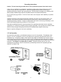
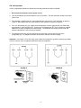
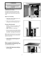
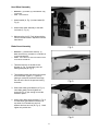
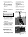
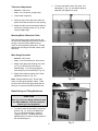
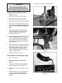
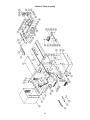
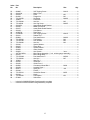
OWNER'S MANUAL
JWCS-10A Cabinet Saw
JWCS-10A-PF Shown
JET EQUIPMENT & TOOLS, INC.
A WMH Company
www.jettools.com
P.O. BOX 1349
Auburn, WA 98071-1349
e-mail [email protected]
Phone:253-351-6000
Fax: 1-800-274-6840
M-708435 12/00
Important Information
2-YEAR
JET offers a two-year limited
warranty on this product
LIMITED WARRANTY
REPLACEMENT PARTS
Replacement parts for this tool are available directly form JET Equipment & Tools.
To place an order, call 1-800-274-6848. Please have the following information ready:
1. Visa, MasterCard, or Discover Card number
2. Expiration date
3. Part number listed within this manual
4. Shipping address other than a Post Office box.
REPLACEMENT PART WARRANTY
JET Equipment & Tools makes every effort to assure that parts meet high quality and durability
standards and warrants to the original retail consumer/purchaser of our parts that each such part(s) to be
free from defects in materials and workmanship for a period of thirty (30) days from the date of purchase.
PROOF OF PURCHASE
Please retain your dated sales receipt as proof of purchase to validate the warranty period.
LIMITED TOOL AND EQUIPMENT WARRANTY
JET makes every effort to assure that its products meet high quality and durability standards and warrants to the
original retail consumer/purchaser of our products that each product be free from defects in materials and
workmanship as follows: 2 YEAR LIMITED WARRANTY ON THIS JET PRODUCT. Warranty does not apply to
defects due directly or indirectly to misuse, abuse, negligence or accidents, repairs or alterations outside our
facilities or to a lack of maintenance. JET LIMITS ALL IMPLIED WARRANTIES TO THE PERIOD SPECIFIED
ABOVE FROM THE DATE THE PRODUCT WAS PURCHASED AT RETAIL. EXCEPT AS STATED HEREIN, ANY
IMPLIED WARRANTIES OR MECHANTABILITY AND FITNESS ARE EXCLUDED. SOME STATES DO NOT
ALLOW LIMITATIONS ON HOW LONG THE IMPLIED WARRANTY LASTS, SO THE ABOVE LIMITATION MAY
NOT APPLY TO YOU. JET SHALL IN NO EVENT BE LIABLE FOR DEATH, INJURIES TO PERSONS OR
PROPERY OR FOR INCIDENTAL, CONTINGENT, SPECIAL OR CONSEQUENTIAL DAMAGES ARISING FROM
THE USE OF OUR PRODUCTS. SOME STATES DO NOT ALLOW THE EXCLUSION OR LIMITATION OF
INCIDENTAL OR CONSEQUENTIAL DAMAGES, SO THE ABOVE LIMITATION OR EXCLUSION MAY NOT
APPLY TO YOU. To take advantage of this warranty, the product or part must be returned for examination,
postage prepaid, to an authorized service station designated by our Auburn office. Proof of purchase date and an
explanation of the complaint must accompany the merchandise. If our inspection discloses a defect, JET will either
repair or replace the product or refund the purchase price, if we cannot readily and quickly provide a repair or
replacement, if you are willing to accept such refund. JET will return repaired product or replacement at JET’s
expense, but if it is determined there is no defect, or that the defect resulted from causes not within the scope of
JET’s warranty, then the user must bear the cost of storing and returning the product. This warranty gives you
specific legal rights, and you have other rights, which vary, from state to state.
JET Equipment & Tools • P.O. Box 1349, Auburn, WA 98071-1349 • (253) 351-6000
2
14. Keep visitors a safe distance from the work
area.
WARNING
1. Read and understand the entire
instruction manual before attempting
assembly or operation.
15. Use recommended accessories; improper
accessories may be hazardous.
16. Never place hands directly in line with the
saw blade.
2. This table saw is designed and intended
for use by properly trained and
experienced personnel only. If you are
not familiar with the proper and safe
operation of a table saw, do not use until
proper training and knowledge have
been obtained.
17. Always use push sticks when cutting small
material.
18. Raise or lower the blade only when the
machine has been turned off and the blade
has come to a complete stop.
3. Always wear approved safety glasses/face
shields while using this machine.
19. Read and understand warnings posted on
the machine.
4. Make certain the machine is properly
grounded.
20. Use blade guard for every applicable
operation including all through cuts. If
guard is removed for special non-through
cuts such as dado and rabbet cuts, replace
before further use of the saw.
5. Before operating the machine, remove tie,
rings, watches, other jewelry, and roll up
sleeves above the elbows. Remove all
loose clothing and confine long hair. Do not
wear gloves.
21. Failure to comply with all of these warnings
may cause serious injury.
6. Keep the floor around the machine clean
and free of scrap material, oil and grease.
7. Keep machine guards in place at all times
when the machine is in use. If removed for
maintenance purposes, use extreme caution
and replace the guards immediately.
22. Some dust created by power sanding,
sawing, grinding, drilling and other
construction activities contains chemicals
known to cause cancer, birth defects or
other reproductive harm. Some examples
of these chemicals are:
8. Do not over reach. Maintain a balanced
stance at all times so that you do not fall or
lean against blades or other moving parts.
•
•
9. Make all machine adjustments or
maintenance with the machine unplugged
from the power source.
•
Lead from lead based paint
crystalline silica from bricks and cement and
other masonry products, and
arsenic and chromium from chemicallytreated lumber.
23. Your risk from those exposures varies,
depending on how often you do this type of
work. To reduce your exposure to these
chemicals: work in a well ventilated area,
and work with approved safety equipment,
such as those dust masks that are
specifically designed to filter out
microscopic particles
10. Use the right tool. Don't force a tool or
attachment to do a job that it was not
designed for.
11. Replace warning labels if they become
obscured or removed.
12. Make certain the switch is in the OFF
position before connecting the machine to
the power supply.
24. Do not operate tool while under the
influence of drugs, alcohol or any
medication.
13. Give your work undivided attention.
Looking around, carrying on a conversation,
and "horse-play" are careless acts that can
result in serious injury.
3
Grounding Instructions
Caution: This tool must be grounded while in use to protect the operator from electric shock.
In the event of a malfunction or breakdown, grounding provides a path of least resistance for electric
current to reduce the risk of electric shock. This tool is equipped with an electric cord having an
equipment-grounding conductor and a grounding plug. The plug must be plugged into a matching outlet
that is properly installed and grounded in accordance with all local codes and ordinances.
Do not modify the plug provided. If it will not fit the outlet, have the proper outlet installed by a qualified
electrician.
Improper connection of the equipment-grounding conductor can result in a risk of electric shock. The
conductor, with insulation having an outer surface that is green with or without yellow stripes, is the
equipment-grounding conductor. If repair or replacement of the electric cord or plug is necessary, do not
connect the equipment-grounding conductor to a live terminal.
Check with a qualified electrician or service personnel if the grounding instructions are not completely
understood, or if in doubt as to whether the tool is properly grounded. Use only three wire extension cords
that have three-prong grounding plugs and three-pole receptacles that accept the tool’s plug.
Repair or replace a damaged or worn cord immediately.
115 Volt Operation
As received from the factory, your tablesaw is ready to run at 115 volt operation. This tablesaw, when
wired for 115 volt, is intended for use on a circuit that has an outlet and a plug that looks like the one
illustrated in (A). A temporary adapter, which looks like the adapter as illustrated in (B), may be used to
connect this plug to a two-pole receptacle, as shown in (B) if a properly grounded outlet is not available.
The temporary adapter should only be used until a properly grounded outlet can be installed by a qualified
electrician. This adapter is not applicable in Canada. The green colored rigid ear, lug, or tab,
extending from the adapter, must be connected to a permanent ground such as a properly grounded
outlet box, as shown in (B).
4
230 Volt Operation
If 230V, single phase operation is desired, the following instructions must be followed:
1. Disconnect the machine from the power source.
2. Turn the handwheel until the saw blade is in the 45° position. This will allow easy access to the motor
junction box.
3. This tablesaw is supplied with four motor leads that are connected for 115V operation, as shown in
Figure A. Reconnect these four motor leads for 230V operation, as shown in Figure B.
4. The 115V attachment plug (A), supplied with the tablesaw, must be replaced with a UL/CSA listed
plug suitable for 230V operation (D). Contact your local Authorized JET Service Center or qualified
electrician for proper procedures to install the plug. The tablesaw must comply with all local and
national codes after the 230 volt plug is installed.
5. The tablesaw with a 230 volt plug should only be connected to an outlet having the same
configuration (D). No adapter is available or should be used with the 230 volt plug.
Important: In all cases (115 or 230 volts), make certain the receptacle in question is properly grounded.
If you are not sure, have a registered electrician check the receptacle.
5
Table of Contents
Warranty .................................................................................................................................................2
Warnings.................................................................................................................................................3
Grounding Instructions.............................................................................................................................4
115V Operation .......................................................................................................................................4
230V Operation .......................................................................................................................................5
Table of Contents ....................................................................................................................................6
Specifications ..........................................................................................................................................6
Contents of the Shipping Container .........................................................................................................7
Tools Included for Assembly....................................................................................................................7
Tools Required for Assembly ...................................................................................................................7
Unpacking and Cleanup...........................................................................................................................7
Installation and Leveling ..........................................................................................................................8
Motor Cover Assembly ............................................................................................................................8
Extension Wing Assembly .......................................................................................................................8
Hand Wheel Assembly ............................................................................................................................9
Blade Guard Assembly .......................................................................................................................9-10
Installing Blade ......................................................................................................................................10
Aligning Blade Guard and Splitter ..........................................................................................................10
Table Insert Adjustment .........................................................................................................................11
Mounting Rails & Extension Table .........................................................................................................11
Miter Gauge Operation ..........................................................................................................................11
Blade Raising & Tilting Mechanism........................................................................................................11
Adjusting 45° and 90° Positive Stops.....................................................................................................12
Wear Adjustment in Raising Mechanism................................................................................................12
Wear Adjustment in Tilting Mechanism..................................................................................................13
Electrical Connections ...........................................................................................................................13
Changing Belts ......................................................................................................................................13
Troubleshooting.....................................................................................................................................14
Cabinet & Table Assembly Parts Breakdown .........................................................................................15
Cabinet & Table Assembly Parts List ................................................................................................16-17
Motor & Trunnion Assembly Parts Breakdown .......................................................................................18
Motor & Trunnion Assembly Parts List ..............................................................................................19-20
Electrical Schematic ..............................................................................................................................21
Specifications
JWCS-10A
Stock Number................................................................................................................................ 708435
Blade Diameter.................................................................................................................................... 10”
Arbor Diameter ................................................................................................................................... 5/8”
Maximum Depth of Cut.................................................................................................................... 3-1/8”
Maximum Rip to Right of Blade ........................................................................................................... 30”
Maximum Rip to Left of Blade ............................................................................................................. 12”
Maximum Thickness at 45° Cut ....................................................................................................... 2-1/8”
Table in Front of Saw Blade at Maximum Cut................................................................................ 11-1/4”
Maximum Width of Dado .................................................................................................................13/16”
Dust Chute Diameter ............................................................................................................................. 4”
Table Height .................................................................................................................................. 34-1/2”
Table Size (with extension)....................................................................................................27”D x 30”W
Table Size (without extension) ...............................................................................................27”D x 20”W
Spindle Speed .......................................................................................................................... 3400 RPM
Motor Size .................................................................................. 1-3/4 HP, 1Ph, 115/230V Prewired 115V
Net Weight (approx.) .................................................................................................................... 277 lbs.
Shipping Weight (approx.) ............................................................................................................ 317 lbs.
The specifications in this manual are given as general information and are not binding. JET Equipment & Tools reserves
the right to effect, at any timeand without prior notice, changes or alterations to parts, fittings, and accessory equipment
deemed necessary for any reason whatsoever.
6
WARNING
Read and understand the entire contents of
this manual before attempting assembly or
operation!
Failure to comply may cause serious injury!
Contents of the Shipping Container
1
1
1
1
1
1
1
1
2
1
Saw w/ Cabinet
Extension Wing
Blade Guard Assembly
Push Stick
Arbor Wrench
Miter Gauge Assembly
Blade Guard Mounting Bracket Assembly
Hardware Bag (blade guard assembly)
Handle Assemblies
Motor Cover
Tools Included for Assembly
1
1
3mm Hex Wrench
Arbor Wrench
Tools Required for Assembly &
Adjustments
1
1
1
1
1
1
1
1
1
8mm Box Wrench
10mm Box Wrench
13mm Box Wrench
14mm Box Wrench
17mm Box Wrench
15/16” Box Wrench
#2 Cross Point Screwdriver
6mm Hex wrench
Straight Edge
Unpacking and Clean-Up
1. Finish removing all contents from the
shipping container. Do not discard any
shipping material until the saw is set up and
running satisfactorily.
2. Inspect contents for shipping damage.
Report damage, if any, to your local
distributor.
7
WARNING
Do not connect the table saw to the power
source until all assembly has been
completed!
Failure to comply may cause serious injury!
Installation and Leveling
Final location for the saw must be level, dry,
well lighted, and have enough room to allow
movement around the saw with long pieces of
wood.
Motor Cover Assembly
1. Install motor cover by aligning pins (A, Fig.
1) brackets on the cabinet.
2. Fasten cover by pulling out latch (B, Fig. 1),
closing the door, and releasing the latch.
Extension Wing Assembly
•
•
Hardware: (3) M10x30 Hex Cap Bolts, (3) M10
Lock Washers, (3) M10 Flat Washers & (1)
Extension Wing
Tools: 17mm Wrench, Straight Edge
1. Mount the extension wing to table with three
hex cap bolts, three lock washers and three
flat washers. Hand tighten only at this time.
Note: Attach the center bolt (A, Fig. 2) first and
then pivot the wing so it lines up with the table.
Attach two more bolts.
2. Slide extension wing toward the front edge
of the saw table until the two edges are
flush, Figure 3.
Note: If the wing is not flush with the table,
there is a possibility of distorting the front fence
rail when tightened to the extension wing. This
may cause the fence to bind.
3. Using a straight edge (A, Fig. 3), align the
extension wing to the saw table and tighten
the hex cap bolts.
8
Hand Wheel Assembly
•
•
Hardware: (2) Handles, (2) Hand Wheels & (2)
Lock Knobs
Tool: 14mm Wrench
1. Attach handle (A, Fig. 4) to hand wheel (B,
Fig. 4).
2. Attach hand wheel assembly to saw with
lock knob (C, Fig. 4).
3. Make sure the pin (D, Fig,4) aligns with the
notch in the hand wheel. Repeat for second
hand wheel.
Blade Guard Assembly
•
•
Hardware: (1) Blade Guard Assembly, (1)
Blade Guard Post (1) M16 Nut & Lock Washer &
(3) M10 Flat Washers
Tools: 13mm Wrench, 3mm Hex Wrench and a
Cross Point Screwdriver
1. Thread a M16 hex nut and M16 Lock
Washer (A, Fig. 5) completely onto the
blade guard post (B, Fig. 5).
2. Thread blade guard post into trunnion at the
rear of the saw, (Figure 5). Tighten by
placing a cross point screw driver through
the hole at the end of the post and turning
clockwise.
3. Slide lower blade guard bracket (A, Fig. 6)
onto blade guard post and tighten set
screws (B, Fig. 6) just enough to hold the
bracket in place.
4. Attach upper blade guard bracket (C, Fig. 6)
to lower blade guard bracket with two hex
cap bolts, four flat washers, two lock
washers and two hex nuts (D, Fig. 6). Hand
tighten only at this time.
9
5.
Insert front tab of blade guard splitter
through insert opening in table and onto hex
cap bolt (A, Fig.7). Hand tighten only at this
time.
2. Using a straight edge (B, Fig. 8), align the
splitter with the saw blade. Be sure that
straight edge rests against body of saw
blade and not saw teeth.
6. Insert rear tab of blade guard assembly
behind two hex cap bolts, two flat washers
and two lock washers (B, Fig. 7) in the
upper blade guard bracket. Hand tighten
only at this time.
3. The upper blade guard bracket (C, Fig. 8)
may need to be adjusted to align the splitter
to the blade.
Note: Make sure anti-kick back plates (C, Fig.
7) are pointing to the rear of the table.
4. Make sure the splitter is level with the table
and approximately 1/8" above the table.
This will allow clearance for tilting blade to
45°.
7. Blade will need to be installed before final
adjustment can be made.
5. When saw blade is aligned with the splitter,
lower the blade, and tighten all hardware
Installing Blade
6. Check alignment again after tightening
hardware. Adjust if necessary.
WARNING
When installing or changing saw blade,
always disconnect saw from the power
source!
Failure to comply may cause serious injury!
•
•
Hardware: Blade
Tools: Arbor Wrench, Scrap Piece of Wood
1. Raise the blade arbor fully and tighten the
lock knob in the middle of the handwheel.
2. Remove the arbor nut and flange (D, Fig.
7). Arnor nut has left hand thread; turn
clockwise to remove.
3. Place the blade on the arbor shaft making
sure the teeth point down at the front of the
saw. Replace the flange and the arbor nut.
4. Place a wood scrap in the blade's teeth.
Hold in such a way that if it slips or the
blade turns, your hand will not contact the
blade.
5. Using the wrench provided, securely tighten
the arbor nut. Remove the wrench.
Aligning Blade Guard and Splitter
•
Tools: 13mm Wrench, 3mm Hex Wrench &
Straight Edge
1. Raise blade guard away from table and hold
anti-kickback pawls away from table surface
with the cut-out in the guard arm, (A, Fig. 8).
10
2. To tilt the saw blade, loosen lock knob, turn
handwheel (C, Fig. 11) until desired angle is
obtained, then tighten lock knob.
Table Insert Adjustment
•
•
Hardware: Table Insert
Tools: 3mm Hex Wrench, Straight Edge
1. Lower blade completely.
2. Place the open end of the insert under the
splitter and lower the insert into the opening.
3. Adjust the table insert flush with the table by
turning four leveling screws (A, Fig. 9) and
using a straight edge.
Mounting Rails & Extension Table
With the extension wing properly aligned, the
rail and fence assembly can now be mounted to
the saw. See the Owner’s Manual for the
XACTA Fence Assembly Instructions. This will
address the mounting of the table, switch, rails
and fence.
Miter Gauge Operation
•
•
Hardware: Miter Gauge
Tools: Cross Point Screwdriver, 8mm Wrench
1. Adjust miter gauge by loosening lock knob
(A, Fig. 10) and turning miter body to
desired angle. To move gauge beyond
index stops, flip down the stop (B, Fig. 10).
2. Adjust index stops by turning one of three
adjustment screws (C, Fig. 10).
Note: Always make test cuts. Do not relay
solely on miter gauge indicator marks. There
are two holes in the miter gauge body that will
allow you to mount an wooden extension face.
Blade Raising and Tilting Mechanism
CAUTION
Never try to force the tilting mechanism past
the 45°° or 90°° stops! This may cause the
blade to go out of alignment!
1. To raise or lower the saw blade, loosen lock
knob (A, Fig. 11), and turn handwheel (B,
Fig. 11) until desired height is reached.
Tighten lock knob. The blade should be
adjusted about 1/8" above the top surface of
the material being cut.
11
5. Tighten the lock nut and reset the pointer.
WARNING
When making adjustments always
disconnect saw from the power source!
Failure to comply may cause serious injury!
Adjusting 45°° and 90°° Positive Stops
•
•
Hardware: Square
Tools: 3mm Hex Wrench, 10mm Wrench
1. Disconnect saw from power source.
2. Raise the saw blade to its maximum height.
3. Set the blade at 90° to the table by turning
the blade tilting handwheel counterclockwise
as far as it will go. Do not force beyond
stop.
4. Place a square on the table and check to
see that the blade is at a 90° to the table,
(Figure 12). Make sure square is not
touching a blade tooth.
5. If blade is not at 90°, loosen nut (A, Fig. 13)
and turn adjusting stop screw (B, Fig. 13) in,
or out. The adjusting stop screw should
stop against the end of the tilting screw (C,
Fig. 13) when the blade is 90° to the table.
Tighten lock nut.
6. Place a square on the table after turning the
blade to the 45° stop. If the 45° stop is not
set properly, loosen nut (E, Fig. 13) and
adjust screw (D, Fig. 13) until the stop
touches the table and the blade is in the 45°
position. Tighten the nut
7. Adjust the pointer for accuracy.
Wear Adjustment in Raising Mechanism
•
Tool: 15/16” Wrench
1. Disconnect the saw from the power
source.
2. Remove lock knob and raising handwheel
but do not remove pointer, (Figure 14).
3. Loosen lock nut (A, Fig. 14) using a 15/16"
wrench.
4. Use the pointer (B, Fig. 14) as a lever and
turn left, or right until all perceptible play
between the worm and arbor bracket is
removed.
12
3. Lift the motor while taking the belts off the
motor pulley.
Wear Adjustment in Tilting Mechanism
1. Disconnect the saw from the power
source.
4. Let the motor hang from the bracket and
remove the belts from the arbor pulley.
2. Loosen lock nut (A, Fig. 15).
5. Replace both belts.
3. Turn eccentric sleeve (B, Fig. 15) until play
is removed. Flat area on sleeve
accommodates a wrench.
4. Tighten lock nut.
Electrical Connections
The JWCS-10A table saw is rated at
115V/230V, prewired 115V.
WARNING!
All electrical connections must be done by a
qualified electrician!
Failure to comply may result in serious
injury!
•
To turn on power to the saw, press the
green start button on the switch assembly
box.
•
To turn off power to the saw, press the red
stop button on the switch assembly box.
In the event the saw stops operating due to the
motor over heating, wait until the motor cools
down, push the reset button on the motor,
and press the green start button to start the saw
again.
Extension Cord Recommendations:
12 Gauge Cord - up to 25'
10 Gauge Cord - up to 50'
8 Gauge Cord - up to 100'
Note: Using extension cords can cause a loss
of power to your machine. It is best if the saw is
plugged directly into an outlet, or a short heavy
gauge extension cord is used.
Changing Belts
1. Disconnect the saw from the power
source.
2. Lower blade completely.
13
Troubleshooting
Trouble
Saw stops or will not start
Does not make accurate 45°° or
90°° cuts
Material binds blade when
ripping
Saw makes unsatisfactory
cuts
Blade does not come up to
speed
Saw vibrates excessively
Possible Cause
Solution
1. Overload tripped on motor
2. Saw unplugged from wall or
motor
3. Fuse blown or circuit breaker
tripped
4. Cord damaged
1. Stops not adjusted correctly
2. Angle pointer not set
accurately
3. Miter gauge out of
adjustment
1. Fence not aligned with blade
2. Warped wood
3. Excessive feed rate
4. Splitter not aligned with
blade
1. Dull blade
2. Blade mounted backwards
3. Gum or pitch on blade
4. Incorrect blade for cut
5. Gum or pitch on table
1. Extension cord too light or to
long
2. Low shop voltage
3. Motor not wired for correct
voltage
1. Allow motor to cool and reset
overload switch on motor
2. Check all plug connections
3. Replace fuse or reset circuit
breaker
4. Replace cord
1. Check blade with square and
adjust stops
2. Check blade with square and
adjust pointer
3. Adjust miter gauge
1.
2.
3.
4.
5.
6.
Stand on uneven floor
Damaged saw blade
Bad V-belts
Bent pulley
Improper motor mounting
Excessive play in raising
mechanism
7. Loose hardware
Rip fence binds on guide rails
1. Guide rails or extension wing
not installed correctly
2. Guide of rip fence not
adjusted properly
Material kicked back from
blade
1. Rip fence out of alignment
2. Splitter not aligned with
blade
3. Feeding stock without rip
fence
4. Splitter not in place
5. Dull blade
6. Letting go of material before
it is past blade
7. Anti-kick back plates dull
Blade does not raise or tilt
freely
1. Too much tension in raising
mechanism
2. Sawdust and debris in raising
and tilting mechanisms
14
1.
2.
3.
4.
Check and adjust fence
Select another piece of wood
Reduce feed rate
Align splitter with blade
1.
2.
3.
4.
5.
1.
Sharpen or replace blade
Turn blade around
Remove blade and clean
Change blade to correct type
Clean table
Replace with adequate size
cord
Contact your local electrical
company
Refer to motor junction box
Reposition on flat, level
surface
Replace saw blade
Replace V-belts
Replace pulley
Check and adjust motor
Adjust worm and arbor
bracket
Tighten hardware
Reassemble guide rails, refer
to fence manual
Adjust guides, refer to fence
manual
Align rip fence with miter slot
Align splitter with blade
Install and use rip fence
Install and use splitter (with
guard)
Replace blade
Push material all the way
past blade before releasing
work
Replace or sharpen anti-kick
back plates
2.
3.
1.
2.
3.
4.
5.
6.
7.
1.
2.
1.
2.
3.
4.
5.
6.
7.
1. Adjust raising worm and
arbor bracket
2. Clean and regrease
Cabinet & Table Assembly
15
Parts List For The JWCS-10A Cabinet & Table Assembly
Index Part
No.
No.
Description
Size
Qty.
1..........290001W ......................... Table............................................................. .................................1
2..........708101............................. Table Insert ................................................... .................................1
3..........TS-1523031 ..................... Set Screw...................................................... M6x10 ......................4
4..........290004W ......................... Extension Wing ............................................. .................................1
5..........TS-1491041 ..................... Hex Cap Bolt ................................................. M10x30 ....................3
6..........TS-1551071 ..................... Lock Washer ................................................. M10 ..........................3
7..........TS-1550071 ..................... Flat Washer................................................... M10 ..........................3
8..........290008W ......................... Cabinet.......................................................... .................................1
9..........200009W ......................... Switch Bracket............................................... .................................1
10 ........994542............................. Switch ........................................................... .................................1
11 ........TS-1482101 ..................... Hex Cap Bolt ................................................. M6x50 ......................1
12 ........998654............................. Strain Relief .................................................. .................................2
13 ........16328............................... Spring............................................................ .................................1
14 ........TS-155004 ....................... Flat Washer................................................... M6x16 ......................1
15 ........IC290001 ......................... Power Cord ................................................... .................................1
16 ........IC290002 ......................... Power Cord (switch to motor)......................... .................................1
17 ........998623............................. Strain Relief .................................................. .................................3
18 ........200018............................. Strain Relief Plate ......................................... .................................1
19 ........ST040200 ........................ Self Tapping Screw ....................................... M4x10 ......................4
20 ........523024............................. Wire Clip ....................................................... .................................2
21 ........TS-1533042 ..................... Pan Head Machine Screw ............................. M5x12 ......................5
22 ........TS-1540031 ..................... Hex Nut ......................................................... M5 ............................1
23 ........ST039904 ........................ Tapping Screw .............................................. M3.5x32 ...................2
24 ........JCS10-9........................... JET Label ...................................................... .................................1
25 ........990805............................. Tapping Screw .............................................. M4x10 ......................2
26 ........TS-1490031 ..................... Hex Cap Bolt ................................................. M8x20 ......................4
27 ........TS-1551061 ..................... Lock Washer ................................................. M8 ............................4
28 ........TS-1550061 ..................... Flat Washer................................................... M8 ............................4
29 ........290029............................. Strain Relief Plate ......................................... .................................1
............290042AS ........................ Blade Guard Assembly Complete (* incl. with blade guard assembly)
30 ........290030A .......................... Splitter * ....................................................... .................................1
31 ........992350............................. Parallel Pin * ................................................ 6x25 .........................1
32 ........200032............................. Anti-Kickback Plate * .................................... .................................2
33 ........200033............................. Spring * ........................................................ .................................1
34 ........200034............................. Spacer * ....................................................... .................................2
35 ........TS-155110 ....................... Lock Washer ................................................. M16 ..........................1
36 ........992315............................. Spring Pin * .................................................. 4x24 .........................1
37 ........200037............................. Support Arm * ............................................... .................................1
38 ........TS-1482081 ..................... Hex Cap Bolt * .............................................. M6x40 ......................1
39 ........TS-1550041 ..................... Flat Washer * ............................................... M6 ............................1
40 ........200040............................. Spacer * ....................................................... .................................2
41 ........TS-1541021 ..................... Nyloc Nut * ................................................... M6 ............................1
42 ........290042............................. Blade Guard * ............................................... .................................1
43 ........992352............................. Pin * ............................................................. 6x45 .........................1
44 ........992501............................. Spring Nut * .................................................. M6 ............................3
............290042AS ........................ Blade Guard Assembly (complete) ................ .................................1
45 ........TS-149006 ....................... Hex Cap Bolt ................................................. M8x35 ......................5
46 ........TS-1550061 ..................... Flat Washer................................................... M8x18 ......................9
47 ........WE050000 ....................... Star Washer .................................................. M5 ............................1
48 ........150056............................. Switch Pad .................................................... .................................1
49 ........TS-1551061 ..................... Lock Washer ................................................. M8 ............................7
50 ........290120W ......................... Deflecter........................................................ .................................1
51 ........TS-2310162 ..................... Hex Nut ......................................................... M16x1.5 ...................1
16
Index Part
No.
No.
Description
Size
Qty.
52 ........990805............................. Self Tapping Screw ....................................... M4x10 ......................6
53 ........290122W ......................... Motor Cover .................................................. .................................1
54 ........290124............................. Knob.............................................................. M6 ............................1
55 ........991002............................. Flange Nut..................................................... M6 ............................1
56 ........TS-1524051 ..................... Set Screw...................................................... M8x20 ......................2
57 ........708818............................. Push Stick ..................................................... .................................1
58 ........TS-1540061 ..................... Hex Nut ......................................................... M8 ............................2
59 ........TS-149006 ....................... Hex Cap Screw ............................................. M8x35 ......................2
60 ........290135N .......................... Upper Blade Guard Bracket........................... .................................1
61 ........290136............................. Blade Guard Post .......................................... .................................1
62 ........290137............................. Lower Blade Guard Bracket ........................... .................................1
63 ........200138............................. Cord Sleeve .................................................. .................................1
64 ........412007W ......................... Dust Chute .................................................... .................................1
65 ........ST040200 ........................ Self Tapping Screw ....................................... M4x10 ......................4
66 ........290141............................. Rubber Pad ................................................... .................................4
67 ........990844............................. Pan Head Screw............................................ M8x20 ......................4
68 ........TS-1550061 ..................... Flat Washer................................................... M8 ............................4
69 ........TS-1551061 ..................... Lock Washer ................................................. M8 ............................4
70 ........TS-1540061 ..................... Hex Nut ......................................................... M8 ............................4
71 ........290146............................. Special Washer ............................................. .................................4
72 ........290147............................. Foam Strip .................................................... .................................1
73 ........200024............................. Splitter Bracket.............................................. .................................1
74 ........200252............................. Arbor Wrench ................................................ .................................1
75 ........200253............................. Hex Wrench .................................................. 3mm .........................1
............JWTS10-MGA.................. Miter Gauge Assembly (** incl. w/miter gauge assembly) ..................
76 ........200151............................. Miter Gauge Body **...................................... .................................1
77 ........TS-1533062 ..................... Pan Head Screw ** ........................................ M5x20 ......................3
78 ........TS-1540031 ..................... Hex Nut ** ..................................................... M5 ............................3
79 ........150031............................. Steel Pin **.................................................... .................................1
80 ........200155............................. Guide Bar ** .................................................. .................................1
81 ........200156............................. Guide Piece **............................................... .................................1
82 ........990530............................. Countersunk Head Bolt ** .............................. M6x8 ........................1
83 ........200158............................. Locating Piece ** ........................................... .................................1
84 ........992311............................. Spring Pin **.................................................. 3x8 ...........................1
85 ........200160............................. Pointer **....................................................... .................................1
86 ........TS-1522011 ..................... Socket Set Screw ** ...................................... M5x5 ........................1
87 ........200162............................. Knob **.......................................................... .................................1
88 ........TS-1550021 ..................... Flat Washer................................................... M4 ............................2
89 ........523028............................. Switch Box .................................................... .................................1
* ..........included in 290042AS Blade Guard Assembly complete
** .........included in 200151AS Miter Gauge Assembly complete
17
Motor & Trunnion Assembly
18
Parts List For The JWCS-10A Motor & Trunnion Assembly
Index Part
No.
No.
Description
Size
Qty.
1..........200035............................. Eccentric ....................................................... .................................1
2..........TS-231014-2 .................... Hex Nut ......................................................... M14x1.5 ...................1
3..........TS-155110 ....................... Lock Washer ................................................. M16 ..........................2
4..........200052............................. Rear Trunnion Bracket................................... .................................1
5..........TS-1490051 ..................... Hex Cap Bolt ................................................. M8x30 ......................2
6..........TS-1551061 ..................... Lock Washer ................................................. M8 ............................2
7..........TS-1550061 ..................... Flat Washer................................................... M8 ............................2
8..........200056............................. Rear Trunnion ............................................... .................................1
9..........290057............................. Connecting Rod............................................. .................................2
10 ........TS-2310162 ..................... Hex Nut ......................................................... M16x1.5 ...................2
11 ........200059............................. Front Trunnion............................................... .................................1
12 ........992322............................. Spring Pin ..................................................... 5x30 .........................1
13 ........200061............................. Locating Block............................................... .................................1
14 ........TS-1482041 ..................... Hex Cap Bolt ................................................. M6x20 ......................1
15 ........TS-1551041 ..................... Lock Washer ................................................. M6 ............................1
16 ........990728............................. Set Screw...................................................... M6x30 ......................1
17 ........TS-1540041 ..................... Hex Nut ......................................................... M6 ............................1
18 ........TS-1482091 ..................... Hex Cap Bolt ................................................. M6x45 ......................1
19 ........TS-1540041 ..................... Hex Nut ......................................................... M6 ............................1
20 ........200068............................. Elevating Shaft.............................................. .................................1
21 ........200069............................. Fiber Washer................................................. .................................1
22 ........200070............................. Eccentric ....................................................... .................................1
23 ........TS-2310162 ..................... Hex Nut ......................................................... M16x1.5 ...................1
24 ........200072............................. Pointer........................................................... .................................1
25 ........TS-1523031 ..................... Set Screw...................................................... M6x10 ......................1
26 ........TS-1550071 ..................... Flat Washer................................................... M10 ..........................1
27 ........200075............................. Hand Wheel .................................................. .................................1
28 ........200076............................. Handle........................................................... .................................1
29 ........992313............................. Spring Pin ..................................................... 3x30 .........................1
30 ........990551............................. Knob.............................................................. M8 ............................1
31 ........200079............................. Front Trunnion Bracket .................................. .................................1
32 ........200080............................. Tilt Shaft........................................................ .................................1
33 ........200069............................. Fiber Washer................................................. .................................3
34 ........200082............................. Setting Collar................................................. .................................2
35 ........TS-1522011 ..................... Set Screw...................................................... M5x6 ........................2
36 ........TS-1550071 ..................... Flat Washer................................................... M10 ..........................1
37 ........200085............................. Bearing Bracket............................................. .................................1
38 ........990844............................. Pan Head Bolt ............................................... M8x20 ......................2
39 ........TS-1550061 ..................... Flat Washer................................................... M8 ............................2
40 ........TS-1551061 ..................... Lock Washer ................................................. M8 ............................2
41 ........TS-1540061 ..................... Hex Nut ......................................................... M8 ............................2
42 ........200075............................. Hand Wheel .................................................. .................................1
43 ........200076............................. Handle........................................................... .................................1
44 ........992313............................. Spring Pin ..................................................... 3x30 .........................1
45 ........990551............................. Knob.............................................................. M8 ............................1
46 ........200094............................. Scale and Warning Label .............................. .................................1
47 ........990805............................. Self Tapping Screw ....................................... M4x10 ......................4
48 ........TS-1490051 ..................... Hex Cap Bolt ................................................. M8x30 ......................2
49 ........TS-1551061 ..................... Lock Washer ................................................. M8 ............................2
50 ........TS-1550061 ..................... Flat Washer................................................... M8 ............................2
51 ........200099............................. Arbor Bracket ................................................ .................................1
52 ........992322............................. Spring Pin ..................................................... 5x26 .........................2
53 ........200101............................. Arbor ............................................................. .................................1
19
Index Part
No.
No.
Description
Size
Qty.
54 ........200102............................. Flange ........................................................... .................................1
55 ........991416............................. Nut ................................................................ 5/8”x12 .....................1
56 ........BB620303 ........................ Bearing.......................................................... 6203LLU...................2
57 ........991172............................. Nut ................................................................ M16x1.5 ...................4
58 ........290106............................. Arbor Pulley................................................... .................................1
59 ........992068............................. Key................................................................ 5x5x40 .....................1
60 ........TS-1523031 ..................... Set Screw...................................................... M6x10 ......................2
61 ........200109............................. Arbor Bracket Shaft ....................................... .................................1
62 ........991901............................. Wave Space Washer .................................... .................................2
63 ........290111............................. Motor Plate Bracket ....................................... .................................1
64 ........TS-1523031 ..................... Set Screw...................................................... M6x10 ......................2
65 ........290113............................. Motor Plate.................................................... .................................1
66 ........MA290001........................ Motor............................................................. 1-3/4 HP, 1 Ph..........1
67 ........IM290001......................... Motor Cord .................................................... .................................1
68 ........290116............................. Motor Pulley .................................................. .................................1
69 ........992068............................. Key................................................................ 5x5x40 .....................1
70 ........TS-1523031 ..................... Set Screw...................................................... M6x10 ......................1
71 ........VB-A30 ............................ V-Belt ............................................................ A30...........................2
72 ........TS-1490041 ..................... Hex Cap Bolt ................................................. M8x25 ......................4
73 ........TS-1550061 ..................... Flat Washer................................................... M8 ............................8
74 ........TS-1551061 ..................... Lock Washer ................................................. M8 ............................4
75 ........TS-1540061 ..................... Hex Nut ......................................................... M8 ............................4
76 ........290130............................. Motor Plate Shaft .......................................... .................................1
77 ........TS-1523031 ..................... Set Screw...................................................... M8x10 ......................4
78 ........ ........................................ Blades (see below list of blades & accessories) .................................
Blades and Accessories
10” x 40T carbide.......................... 709733
10” x 60T carbide.......................... 709734
Featherboard ................................ 709721
Switch Padlock ............................. 709012
Tool Saver Cover ......................... 708156
6” x 16T dado ............................... JB1710
Dado Insert ................................... 708102
Right Tilt No-Clearance Insert....... 709380
Tenoning Jig................................. 708111
Mobile Base.................................. 708133
XACTA Lift ................................... 708124
Outfeed Rollers ............................ 708150K
Scoring Saw Attachment............... 709690
20
21