1
ProstyleTM Grill Cooktop
Model
DP Gas
Triple
Bay JGD8348B
Conventional
_ wEsT
FOURTHSTREET.
NORTH.
NEWTON.,A
_JENN-AIF_
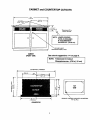
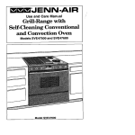
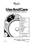
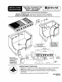
Dimensions
showninbothinchesand centimenters
NOTICE TO INSTALLER: Leavetheseinstructions
withtheappliance.
NOTICE TO CONSUMER: Retain
theseinstructions
forfuture
reference.
%
j_
23,81crn
SEE PAGE2
FOR CUTOUT
SELECT
APPROPRIATE
DUCTCUTOUT
1"
,i
(SEEDUCTING
INSTALLATION
INSTRUCTIONS.)
15o
"
_9.6B crn,5 3/4 •
PRESSUREREGULATOR
cm] .__
[38.1
3 13/16"
APPL
I ANCE
46 13/16"
I
I
,,r
DIMENSIONS
L, I'-
[11S.90
"I
¢m]
I
.....
,_
'
,s,B,,o.
®
' 1,°oco,
"
_L®®
• Blower may be
rotated
CLEARANCE
for horizontal
[40.16cm]
REQUIRED
MIN.
or vertical directionby
_
looseningnuts
Accessible inside
around blower inlet.
ventilationchamber.
__t
_
TT(_ABO BAFFLE
CF
_
I[_--
"BLIIER
14
APPLIANCE
PRESSURE
REGULATOR
BOX
3, 4°
EACH END..___.,._
EOVER/
DRAIN JAR
14,
A-_
i:_;
_
28 11/16°
c_]
[72.87
cm]
"/
3 5,16.
'
BOTTOMOF
BURNERBOX
[8 41 c'_}
END OF
BOX
BURNER
•
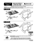
Dimension "A" - provide 2" rain. (5.08 cm) cabinet clearance to motor for cooling purpose.
•
•
NOTE: Where possible, 6" (15.54 cm) is recommended for motor/blower service.
Side Clearance: Grills installed near a side wall must allow a minimum clearance of
8" (20.32 cm).
•INSTRUCTIONS
Access must be provided
to remove and empty grease container.
TO INSTALLER:
8101P399-60
(09-01-00)
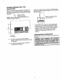
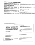
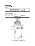
CABINET and COUNTERTOPCUTOUTS
(115.2 cm)
22_" Ref
(58,11 cm)
17.46--22.86 crn)
*Recommend
8"for
Custom
Cabinetry.
O
O_
NOTE: LOWER CONTROL
PANEL IS REQUIRED
IF THIS DIMENSION
EXCEEDS 5_/_" (14.60 crn).
\
SEE PAGE 3 ABOUT
i"
1"
CABINET
(FRONT
VIEW)
REINFORCING CABINET FRONT
See cutout suggestions 1-4 on page 6.
NOTE: Tolerances for Cutout
Dimensions are ± 1/16 in (.16 cm)
I
I
As requiredby installation
(116,2 cm]
227/6"Re1
(58.11
crn_------
l
=o
==
I
TOP
I_ _-_
VIEW
O
°
/
'p
4613/16"
(118.90
cm
COUNTERTOP
_
I --
\
REMOVECORNERSUPPORTS
TYP.(4) PLS. AS NEEDED
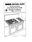
InstallingCabinetry Over Your
Jenn-Air Grill
Minimum horizontal clearance between the edge of the
applianceand combustibleconstructionextendingfrom
the cooking surface to 18" (45.7 cm) above the cooking
1=/_"
8"
Avoid use of cabinetsabove cooktopfor storage space to
eliminate associated potential hazards such as reaching
over open flames.
(4.45 cm) at rear
(20.32 cm) at sides
surface This
is: is not the recommended clearance, but
NOTE:
minimum al,owable clearance.
Dotted lines indicate range
,.,_ t"--_--"l-_" __
hood construction.
* To
heated
eliminate
surface
theunits,
risk of
cabinet
burns storage
or fire byspace
reaching
located
over
above the surface units should be avoided. If cabinet
18,
(45,7 ¢m)
installing a range hood that projects horizontally a
_
I_ _
_
(_ (_ _
_ (_ "_
.38"om
MIN.CLEARANCE
• A = 30" (76.2 cm) minimum vertical clearance
between cooking surface and construction above
the appliance.
B = 13" (33.02 cm) maximum depth of cabinets
installed above cooking top.
cabinets.minimum
inches
beyond
the
storage is of
to 5be
provided,
the the
riskbottom
can beof
reduced
by
CabinetsAbove Cooking Top
Maximum depth of cabinets installed above cooking top is
13 inches.
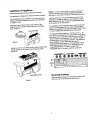
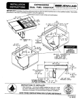
Installation Of Appliance
Follow accompanying ducting instructions carefully.
This appliance is designed to always be vented outdoors,
NOTE: For some cabinet styles, it may be necessary to
reinforce the front of the cabinet by attaching a brace
from front to rear inside the cabinet under the Burner Box.
The Countertop Cutout, Cabinet Front Cutout and Duct
Opening should be prepared according to the illustration
on pages 1 and 2.
Installductwork per ducting instructions provided. Duct
openings in cabinet are shown in the drawing on page 1.
Make electrical and gas connections as described below
Installthe Lower Control Panel in the bottom of the
in this section of the instructions.
Cabinet Cutout as shown using screws from Hardware
pack. (Figure 1).
The installationof this appliance must conform with local
codes or, in the absence of local codes, with the latest
editionof the National FuelGas Code, ANSI Z.223.1 USA
Tl_pVlml
Figure 1
LOWER_
L.
I _=,,_l
PANEL
II
LF
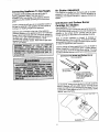
Position unit in the Countertop Cutout. Main Control Panel
should overlap top of Lower Control Panel as shown.
(F{gure 2).
The electrical supply required is 110/120--volt,A.C., 15
amp, 60 Hz. This appliance is equipped with a grounded
type power cord. A grounded outlet must be provided. It is
recommended,
for convenience,
this outlet be
located in
or current CAN/CGA-B149
INSTALLATION
CODE.
the area shown in the shaded illustration. This appliance,
when installed, must be electrically grounded in
accordance with local codes or, in the absence of local
codes, with the latest edition of the National Electrical
Code ANSI/NFPA No. 70 USA or current CSA
STANDARD C22.1 Canadian Electrical Code part 1.
¢¢®e
.EL
F_gure2
e,,-= ¢ ®
Servicing Cooktop
When servicing cooktop it is necessary to remove the
main top, prior to removing the control panel.
ConnectingAppliance To Gas Supply
Air Shutter Adjustment
A TRAINED SERVICEMAN OR GAS APPLIANCE
INSTALLER MUST MAKE THE GAS SUPPLY
CONNECTION. Leak testing of the appliance shall be
conducted by the installer according to the instructions
given.
This appliance is shipped from the factory with air shutters
adjusted for use with Natural Gas. If further adjustment is
necessary, or to reset for use with LP, adjust air shutters as
follows:
Install a manual shutoffvalve in an accessible location in
Grill Burner and Surface Burner
Cartridge Air Shutters
the gas line external to thisappliance for the purpose of
turning on or shuttingoff gas to the appliance.
Make the gas connectionto the inlet of the appliance
pressure regulatoron this appliancewith a 1/2" male pipe
thread. Use an approvedpipe joint compoundresistantto
the actionof LP gas at pipeconnections.Test all joints for
gas leaks with a soap and water solutionor other
accepted leak detectionmeans. Never test for gas leaks
with an openflame,
(See///ustrations "A" & "B')
The left hand air shuttercontrolsthe rear half of the burner.
The fight handshutter controlsthe front half. Access to air
shutters on the surface burner cartridge may be found
throughopeningson the bottomof the cartridge housing.
Slide air shutters backward or forward to increase or
decrease the size of the air opening.Air shuttersfit snugly,
soa screwdriverblade or needlenosepliers may be required
to make this adjustment(see illustration).
Observe change in flame appearance as the air shutter is
moved. Adjustmentis satisfactory when a clearly defined,
even blue flame resultsat the high flame setting. The snug
fit of theairshutterassurasit willremainpositionedcorrectly.
I
Grill Burner Air Shutter and Surface Burner
(if so equipped)
AIRSHU'CrER
_
/
_-- INSERT
SCREWDRIVER
BLADE
INSLOTANDTWIST
WITHSLIGHT
PRESSURE
TO
ALLOW
AIRSHUTTER
TO
SLIDEEASILY
Illustration ",4"
On any burner, closing the air shutter too far will cause the
flame to become soft and yellow tipped. Opening the air
shutter too wide will cause the flame to blow away from the
burner ports. Proper adjustment will produce a sharp, clearly
defined, even blue flame.
Illustration "B"
_'-_--J"
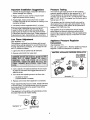
Important Installation Suggestions
Pressure Testing
1. Chamfer all exposed edges of decorative laminate to
prevent damage from chipping,
2. Radius corners of cutout and file to insure smooth
edges and prevent comer cracking,
The maximum gas supply pressure for the appliance
pressure regulator supplied on this appliance is 14" W.C.
The test pressure for checking this appliance pressure
regulator must be at least 6" W.C. for Natural Gas, and at
least t 1" W.C. for LP. It is shipped from the factory set for
Natural Gas at 5" W.C.
3. Rough edges, inside corners which have not been
rounded and forced fits can contribute to cracking of the
countertop laminate.
4. Countertop must be supported within 3" of cutout,
On any burner, closing the air shutter too far will
cause the flame to become soft and yellow tipped.
Opening the air shutter too wide will cause the flame
to blow away from the burner ports. Proper adjustment
will produce a sharp, clearly defined, even blue flame,
This
appliancefrom
andthe
its individual
shutoff
must
be
disconnected
gas supply
pipingvalve
system
during
any pressure testing of that system at test pressures in
excess of 112"PSIG (3.5 k Pa).
This appliance must be isolated from the gas supply
piping system by closing its individual manual shutoff
valve during any pressure testing of the gas supply piping
system at test pressures equal to or less than 1/2" PSIG
(3.5 k Pa).
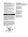
Low Flame Adjustment
(See Illustration "C")
This appliance is shippedfrom the factory with low and
medium flame settingsadjustedfor use with NaturalGas.
If further adjustment is necessary, or to re-adjustfor use
with LP, proceedas follows:
Appliance Pressure Regulator
Conversion
(See Illustration "D")
This unit is supplied with a Maxitrol Appliance Pressure
Regulator.Followthe instructionsin illustration"D".
1. Lightburner and set controlknobfor low flame.
2. Remove control knob from valve stem.
MAXlTROL APPLIANCE PRESSURE REGULATOR
APPLYDOWNWARD
FINGERPRESSURE
ATDISCEDGESTO
CAP
CONVERT
ER_I
I
AND PIN..,,,-".
NAT _../.,"
r,
3. Insert a slender, thin-blade screwdriver into the recess
at center of valve stem and engage blade with slot in
adjusting screw.
4. Turn center stem adjusting screw to set flame size.
• . . clockwise to reduce.
... counterclockwise to increase.
5. Replace control knob when adjustment is completed.
Proper adjustment will produce a stable, steady blue flame
of minimum size. The final adjustment should be checked
by turning knob from high to low several times without
extinguishing the flame.
This adjustment, at low setting, will automatically provide
the proper flame size at medium setting.
CLOCKWISE
TOREDUCE
Illustration "C"
colJwr
ERCLOCK'WISE
TO INCREASE FLAME
SIZE
_
LP
_
TI
_
NA
APPLY
REPLACEPIN IN CAP
SIDEWARDFINGER
REMOVEPiN
-PRESSURETO
!LP
Ii_FROM
Illustration "D"
CAP
II_
Conversion To LP Gas
Control Settings
This appliance is shipped from the factory equipped for
use with Natural Gas. To convertit from NaturalGas for
use with LP Gas, performsteps 1 through4.
1. Remove Natural Gas orificehoods.Installcolor coded
orificehoodssupplied.Located in a packattachedto
the outer plenumarea of this appliance,
The size and type of cookwareand the amountand type
of foodbeing cookedwill influencethe settingneededfor
bestcookingresults.The settingindicatedshouldserve as
a guidewhile you become familiarwith your cooktop.
(See Illustration"E", below,and LP Gas Conversion
instructionspage 8).
2. _nvertcap in convertiblepressureregulator(if so
equipped)locatedat entranceto gas manifold,
3. Adjustair shutterson individualburnersfor proper
flame appearance.
4. Adjustlow flame settingat each burnerby turning
adjustmentscrew in center ofvalve stem.
To make these conversionsadjustmentsfollowthe
instructionsand illustrations("A" through"E", pages
5-7).
Apply a non-corrosiveleak detectionfluid to all joints
and fittingsin the gas connectionbetweenthe supply
lineshut-offvalve and the range. Includegas fitting
and jointsin the range if connectionswere disturbed
during installation.Check for leaks! Bubblesappearing
aroundfittingsand connectionswillindicatea leak, If a
leak appears,turn off supplylinegas shut-offvalve,
tightenconnections,turn on the supplyline gas shut
off valve, and retestfor leaks. Never test for gas leaks
with an openflame.
This appliance is shipped from the factory with orifice
hoods drilled for use with Natural Gas. To convert from
Natural Gas to LP, apply a 112"open-end wrench to hex
section of orifice hood. Turn counterclockwise to remove.
Save the Natural Gas orifice hoods just removed from this
appliance for future use. Install color coded orificehoods
supplied. (See LP Gas Conversion instructions above and
page 8). Turn clockwise to install. Hold dimension
specified in illustration "E".
1/2" OPEN END
WRENCH
_
J
CLOCKWISE
TURN
COUNTERCLOCKWISE
TO REMOVE
•
1
_
TO TIGHTEN
TURN
ORIFICE HOOD
Illustration "E"
Use the HI flame settingto
quicklybringfoodsto a boilor to
begina cookingoperation.Then
reduce to a lower settingto
continuecooking.Never lease
foodunattendedover a HI flame
setting.
Med settingis used to continuea
cookingoperation.Food will not
cook any fasterwhen a HI flame
settingis used than that needed
to maintaina gentleboil.
Remember,water boilsat the
same temperaturewhether boiling
gentlyor vigorously.
Use LO settingto keep food at
servingtemperatureswithout
further cookingYou may find that
some cookingmay take place if
the cookwareis covered.
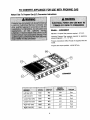
TO CONVERTAPPLIANCE
FORUSEWITHPROPANE
GAS
Natural GasTo PropaneGas (LP)Conversion
Instructions
Models- JGD8348BDP
Manifold - Propane Gas pressure required - 10" W.C.
Incoming Propane Gas pressure required to appliance
pressure regulator- 11" - 12" W,C.
Propane Conversion Orifice Hoods are supplied with this
model.
Propane Gas input specified - 46,000 BTU/hr.
Q
,_
JGD8348BDP
Left Rear (LR)
7500
#66
.033
Zinc
Left Front (LF)
7500
#66
,033
Zinc
Center Rear (CR)
6500
#68
.031
Red
Center Front (CF)
9000
#63
.037
Blue
Right Rear (RR)
6500
#68
.031
Red
Right Front (RF)
9000
#63
.037
Blue
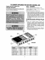
TO CONVERTAPPLIANCE
FORUSEWITHNATURAL
GAS
PropaneGas(LP)To NaturalGas
Conversion
Instructions
Model- JGD8348BDP
If this appliance has been converted for use with LP Gas,
each of the following modifications must be performed to
convert the unit back to Natural Gas.
Incoming Natural Gas pressure required to appliance
pressure regulator - 6" - 7" W.C.
Manifold - Natural Gas pressure required - 5" W.C.
Natural Gas input specified - 56,000 BTU/hr.
A. Replace all orifice hoods - Perform steps 1 through 4 on
page 7. Locate the (6) six Natural Gas hoods (with small
numbers stamped on their sides saved from the original
Natural Gas unit). Page 5 Illustration "E'. The two
hoods with .0520 (#55 orifice) stamped on them are for
the left front and left rear burners. The four hoods with
the .0595 (#53 orifice) stamped on them are for the two
right burners.
To make these conversion adjustments follow the
instructions and illustrations ("A" through "E") pages
5-7.
B. Invert cap in appliance pressure regulator (see
Illustration "D", page 6). With the appliance installed,
the appliance pressure regulator is located on the right
underside of the appliance at the inlet to the gas
manifold. Identify the type of appliance pressure
regulator on the unit and follow the instructions in the
appropriate illustration.
C. Adjust low flame setting for each burner. Follow the
instructions for burner low flame adjustment on page 7
to increase the simmer flame size.
Q
Q
JGD8348BDP
Left Rear (LR)
8,000
#55
.0520
Green
Left Front (LF)
Center Rear (CR)
8,000
10,000
#55
#53
.0520
.0595
Green
Brass
Center Front (CF)
10,000
#53
.0595
Brass
Right Rear (RR)
10,000
#53
.0595
Brass
Right Front (RF)
10,000
#53
.0595
Brass
9
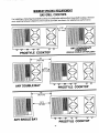
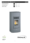
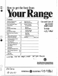
MINIMUM
SPACING
REQUIREMENT
GASGRILLCOOKTOPS
For installinga Triple Bay Downdraft Cooktopin combinationwith another Downdraft Cooktop,the minimum spacing between adjacent units must be provided, as shown, for satisfactory performance.
_
_
_
_
_
_,
PROSTYLE COOKTOP
L.
18"
,=
(45.7 cm)
r
ANY DOUBLEBAY
ANY DOWNDRAFT
COOKTOP
(SINGL_,
OOUeLE
OnTRmPLE
eAY
_= _
_
_ _
_ _
PROSTYLE COOKTOP
I
-'_
<
ANY SINGLEBAY
(45.7crn)
,,:o
k
,
_= _ _= _ _
_
PROSTYLE COOKTOP
10
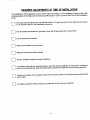
REQUIRED
ADJUSTMENTS
ATTIMEOFINSTALLATION
The installation of this appliance must conform with local codes, or in the absence of local codes, with
the latest edition of the National Fuel Gas Code ANSI Z223.1 USA or current CAN/CGA-B149 Installation
Code.
--'--I
to
This
LPrange
procedure
was manufactured
found in the installation
for usewith instructions.
NaturalGas. IfLP gas isthe fuel of choice, follow the conversion
Test all external connectionsfor gas leaks. Never test for gas leaks with an open flame.
Test all electrical connections.
_
Adjust all air shutters for proper flame.
F-"-_ Adjust all valves for low flame settings.
['-_
Test the ventilation system for proper installation.
If a Jenn-Air
the
problem exists
specifications.
with the downdraft
Most downdraft
system,
system
checkproblems
the ducting
areinstallation
attributed to poor
makeducting
sure it conforms
practices.to
cuts
of meat.
Contact
your installer if the ventilation system will not remove smoke or cooking fumes from well trimmed
[_
-]
If ventilation problems persist contact your authorized Jenn-Air Service Contractor.
11