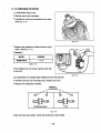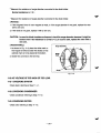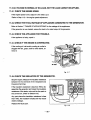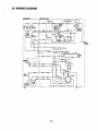
1
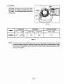
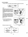
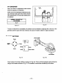
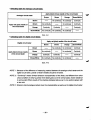
MAN,UAL
Model
RGD5000
Generator
PUB-GS1187
Rev. 8198
.
CONTENTS
nt/e
section
.
Page
.......................................................................................................
1 SPECIFICATIONS
.
...........................................................................................
2 PERFOMANCE CURVES
2-1 MODEL RGD5000 ..................................................................................................
2-2 DC OUTPUT .........................................................................................................
1
2
2
2
.
.................................................................................................................. 3
4.GENERAL DESCRIPTION
.......................................................................................... 4
3 FEATURES
4-1 EXTERNAL VIEW .................................................................................................
4-2 CONTROL PANEL ................................................................................................
4-3 LOCATION of SERIAL NUMBER and SPECIFICATION NUMBER......................
.
...........................................................................
5 CONSTRUCTION AND FUNCTION
4
5
6
7
5-1 CONSTRUCTION ................................................................................................. 7
5-2 FUNCTION............................................................................................................
7
5-3 GENERATOR OPERATION ................................................................................
11
*-
.
......................................................................................... 14
7. RANGE OF APPLICATIONS .................................................................................... 15
8. MEASURING PROCEDURES..................................................................................
18
6 SAFETY PRECAUTIONS
8-1 MEASURING INSTRUMENTS ...........................................................................
8-2 AC OUTPUT MEASURING .................................................................................
8-3 DC OUTPUT MEASURING .................................................................................
8-4 MEASURING INSULATION RESISTANCE ........................................................
9 CHECKING FUNCTIONAL MEMBERS
9-1 VOLTMETER .......................................................................................................
9-2 AC RECEPTACLES ............................................................................................
9-3 NO-FUSEBREAKER ...........................................................................................
9-4 STATOR ..............................................................................................................
9-5 ROTOR ASSEMBLY ...........................................................................................
9-6 CONDENSER .....................................................................................................
9-7 DIODE RECTIFIER .............................................................................................
10 DISASSEMBLY AND ASSEMBLY
10-1 PREPARATION and PRECAUTIONS ...............................................................
10-2 SPECIAL TOOLSfor DISASSEMBLY and ASSEMBLY ....................................
....................................................................
.
.
”
..........................................................................
18
21
21
22
24
24
24
24
25
26
27
27
29
29
29
Section
Tile
10-3 DISASSEMBLY PROCEDURES .......................................................................
10-4 ASSEMBLY PROCEDURES .............................................................................
paw
30
39
10-5 CHECKING. DISASSEMBLY and REASSEMBLY of the CONTROL BOX ....... 50
.
............................................................................................
.
.................................................................................................
11 TROUBLESHOOTING
52
11-1 NO AC OUTPUT................................................................................................
52
S TOO THIGH OR TOO LOW...................................................
54
11-2 AC VOLTAGE I
11-3 AC VOLTAGE IS NORMALAT NO-LOAD. BUTTHE LOAD CANNOT BE APPLIED ..... 55
11-4 NO DC OUTPUT ............................................................................................... 56
12 WIRING DIAGRAM
57
Model
RGD5000
Brushless, Self Exciting, 2-Pole, Single Phase
JYPe
60 Hz
Frequency
a
5g !
AC
Maximum Output
5000 W
Rated Output
4500 W
120 v
51
a
Current
1
I
12OV/24OV
I
37.5 A
1.o
Power Factor
DC Output
12 V-8.3 A (100 W)
I
Regulator
Voltage
Type
Condenser
Air-Cooled 4-Cycle, Diesel Engine
Model
DY41 D
tcDisplacement
[I
412 cm3 (25.14 cu. in.)
Rated Output
8.5 HP / 3600 rpm
~
W
37.5N18.814
II
I
~~
~
~~
Diesel lightoil
Fuel
~~~
~
~
Fuel TankCapacity
1
1
4.2 U.S. gal. (16.0 liters)
1
Rated Coutinuous Operation 1
2.0 hours
Oil Capacity
Starting
System
Dimensions (L x W x H)
2.3 U S . gal. (1.1 liters)
i
I
Electric Starter
Recoil
Starter
and
26.5 x 19.7 x 21.3 in (675 x 500 x 542 mm)
Dry Weight
95 kg (209Ibs.)
Electric starter motoris available as option.
- 1-
I
2. PERFOMANCE CURVES
2-1 MODEL RGD5000
t
-
-63
P
*
zi= 6 610
E
K
Y
1
s:
-g
2
Output Max. ................. 5000 W
Output Rated ............... 4500 W
Frequency .................... 60 Hz
Voltage ......................... 120 V
5k
62
4k
59
2k
t
-2
c
c
130
3
lk 0
120
110
h
-
3
10
20
30
CURRENTO
0
0
50
40
Output Max. .............. 5000 W
Output Rated ............4500 W
Frequency .................60 Hz
Voltage ...................... 120 Vl24OV
2-2 DC OUTPUT
DC Voltage .................. 12 V
-=
DC Ampere
.................8.3 A
DC output ....................
I6
Lu 14
The voltage cuwe shown in the left indicates the characteristic of DC output when charging a battery. The
voltage may be decreased by 20% when the resistance loadis applied.
12
gIO
0
100 W
2
-
4
6
8
CURRENT(A)
1
NOTE :It is possible to use both DC and AC outputs
simultaneouslyup to the rated output in total.
0
-
2-
*
3.FEATURES
3-1 BRUSHLESSALTERNATOR
Newly developed brushlessalternator eliminates troublesome brush maintenance.
3-2 EASY STARTING
Light pull recoil starter accompanied with automatic decompression system makes the new RGD series
generators even easier instarting than gasoline engine generators.
3-3 QUIET OPERATION
The new RGD series generator provides quiet operation by means of:
The superb design of intake-exhaust system.
Direct injection combustion system.
0 A large super silent muffler.
An efficient low noise air cleaner.
3-4 ECONOMICALPERFORMANCE
On top of well known diesel economy, the air-cooled Robin diesel engine features direct fuel injection
and special design refinements for extra fuel efficiency.
3-5 OIL SENSOR
The OIL SENSOR automatically shuts the engine off whenever the oil level f& down below a safe level
preventing engine seizure.
3-6 COMPACT, LIGHT WEIGHT
The combination of newly developed brushless alternator and air-cooled single cylinder Robin diesel
engine enables the new RGD series generators to bevery compact in size and light in weight.
3-7 RELIABLE PERFORMANCE WITH MINIMAL MAINTENANCE
A brushless alternator eliminates troublesome brush maintenance.
A dripproof alternator design.
A trouble free condenser voltage regulator.
A fuseless circuit breaker.
A dust-proof oil-bath air cleaner.
The OIL SENSOR automatically shuts the engine off whenever the oil level falls down belowa safe
level preventing engine seizure.
3-8 LONG-LIFE DURABILITY
0
0
Compact and smooth running air-cooled Robin dieselengine lasts much longer than the gasoline
engine of the same size.
Trouble-free brushless alternator with condenser type voltage regulator works all the year round
without any maintenace work.
- 3-
4.GENERAL DESCRIPTION
4-1 EXTERNAL VIEW
Rocket cover
Fuel gauge
\
Air cleaner
\
ACreceptack
\
Tank cap
/
- 4-
Muffler
4-2 CONTROL PANEL
RGD5000 : 60HZ-l20V, 60Hz-l2OV/240VTYPE
Voltmeter
Full power switch
AC
Earth terminal
- 5-
DC output terminal
4-3 LOCATION of SERIAL NUMBER and SPECIFICATION NUMBER
Serial number and specification number are stamped onLABEL
the (MODEL NAME) stuck on the side
wall of control box.
NOTE :Always specify these numbers when inquiring about
the generator or ordering spare parts in
order toget correct parts and accurate service.
Serial number
- 6-
e
5CONSTRUCTIONAND FUNCTION
"
!j-lCONSTRUCTlON
Mount rubber
Generator base
\
Driving shaft
Starterpu"ey
Stator bolt
Ball bearing
Fig. 5-1
5-2 FUNCTION
5-2-1 STATOR
Thestatorconsists of alaminatedsiliconsteel
sheet core,a mainc o i l and a condenser coil which
are woundin the core slots.
I
The condenser coil excites the rotor field coil which
generates AC voltage in the main coil.
Fig. 5-2
- 7-
\
Adapter
5-2-2 CONDENSER
One or two condensers are installedin the control box and are connected to the condenser coil
of the stator.
These condensers and condenser coil regulate
the output voltage.
5-2-3 ROTOR
The rotor consists of a laminated silicon
s t e e l sheet
is wound over the core.
core anda field coil which
DC current in the field coil magnetizes the steel
sheet core.Two permanent magnets are provided
for the primary exciting action.
Fig. 5-4
A diode rectifier and surge absorber
is mounted insideof the insulator.
Fig. 5-5B
Fig. 5-5A
- 8-
5-24 DC FUSE
(1) The 10 ampere DC fuse mounted on the control panel protectswhole DC circuit from getting damage by overload or short circuit.
(2) The 15 ampereDC fuse in the control box protects the diode rectifier from getting damage
by reverse connection to the battery.
(Electric start model)
L
Fig. 5-6
5-2-5 NO-FUSE BREAKER
The no-fuse breaker protects the generator from getting damage
by overloading or short circuit in the
of protection.
appliance.Table 5-1 shows the capacityof no-fuse breaker by each spec. and their object
MODEL
SPECIFICATION
NO-FUSE BREAKER
OBJECT or PROTECTION
37.5 A
Total output amperage
Output from 30A receptacle
Total output amperage
Output from 3OA receptacle
60 HZ-120V
30 A
RGD5000
/-
20Ax2
60 HZ-120V, 240V
30 A
Table. 5-1
Fig. 5-7
-
9-
5-2-6 RECEPTACLEand AC PLUG (STD.SPEC.)
These areused for takingAC output power from the generator.
A total of six kindsof receptacles, each
varying in rated voltage and current from another, are used. Each model has at least one receptacle to
output. As many AC plugs as the receptacles, each matching the corresponddeliver the rated generator
ing receptacle, are provided. Table 5-2 shows the rated current for each receptacle. Be careful not to use
to prevent burning.
the receptacles andAC plugs beyond the specified amperage limits
w
I'
W
NOTE 1 :If your generator has receptacles pecu5-2 does not
liar to your country, Table
apply.
NOTE 2 :The generator for U.S.A. market is
equipped with NEMA standard receptacles shown in table5-2.
Use the proper plug for connectingappliance to the generafoE
Caution :To connect the applianceto locking
receptacle, insert the plug into the r e
ceptacle and turn it clockwiseto lock
Fig. 5-8
style
El
Ampere
125V
20A
Receptacle
AC plug
NEMA
NEMA
5-20R Circuit Interrupter)
5-20P
Description
GFCI
(Ground Fault
Receptacle, duplex
@
125V/ 250V
20A
NEMA
L14-20R
NEMA
L14-20P
Locking Receptacle
@
125V
30A
NEMA
NEMA
L5-30P
Locking Receptacle
E-30
Table. 5-2
- 10-
PERMANENT
MAGNET
STATOR
FOR INITIALEXCITATION
COIL
FIELD
,I
APPLIANCE
"
"
"
I
I , """"
fig,5-9
5-3-1GENERATlON Of NO-LOAD VOLTAGE
(1) When the generator starts running, the permanent magnet built-in to the rotor generates
3 to 6V of AC
voltage inthe maincoil and condenser coil wound on the stator.
(2) As one ortwo condensers are connected to the condenser coil, the small voltage at the condenser
which
I
flows through the condenser coil. At this time, a smallis flux
coil generatesa minute current@
produced with which the magnetic force at the rotor's magnetic is
pole
intensified.When this magnetic force is intensified, the respective voltages in the main
coil and condensercoil riseup. As the
current @$increases, the magnetic flux at the rotor's magnetic pole increases further. Thus the voltages at the main coil and condenser coil keep rising
by repeating this process.
(3)As AC current flows through the condenser coil, the density of magnetic flux in the rotor changes. T
in the field coil
change of magnetic flux inducesAC voltage in the field coil, and the diode rectifier
circuit rectifies thisAC voltage intoDC. Thus aDC current @ flows through the field coil and magnetizes the rotor coreto generate an output voltage in the main coil.
(4) When generator speed reaches3000 to 3300 rpm, the current in the condensercoil and field coil
to stabilize the output voltage of each coils. If generator speed further
increases rapidly. This acts
will reach to the rated value.
increases to the rated value, the generator output voltage
5-3-2 VOLTAGE FLUCTUATIONS UNDER LOAD
When the output current
@ flows through the main coil to the appliance, a magnetic
is produced
flux
and
@
in the
I condenser coil. When current increases, the densityof magnetic
serves to increase current
As a result, the current flowing the
in field coil increases and
the generaflux across the rotor core rises.
tor output voltage is prevented from decreasing.
a
-
11
-
5-34 FULL POWER SWITCH (Dual Voltage Type)
The full power switch is provided for the dual voltage type
to take out thefull rated power from one
receptacle in eachvoltage.
I
Fig. 5-10
L
\
3MCz
/
Fig. 5-11
w
LOWER VOLTAGE HIGHER VOLTAGE
Switch
1
110 v
lgv
I
RECEPTACLE RECEPTACLE
Rated output
No output can be
taken.
11 o m 0 v
or
120/240v
Half of rated output
Table. 5 4
-
12
-
Rated output
.-
Two main coils are wound over stator core. Each main coil outputs half the rated power at the lower
Thepower switch
voltage (11OV or 120V). These main coils are wound to be in the same phase. full
reconnects these main coils
in parallel or in series.
Fig. 5-10 shows a circuit diagram. When the full power switch
is set for single lower voltage indication
(11OV or 120V), the switch positionis as indicated by the lower solid line
in the diagram. Fig.5-11 is a
simplified representation of this circuit, showing two
the main coils connected
in parallel.ln this case, the
higher voltage(220V or 240V) at Rec. 3 cannot be taken out. Rec.
2 for the lower voltage
can output up
to the rated power (up
to 30A if the rated current is over
30A), and Rec.1 can output up to a total of15A.
When the full power switch is set for double voltage indication
(11OV/22OV or 120V/240V), the switch
line
Fig. 5-10. Fig. 5-12 is a simplified representation of this
position is as indicated by the upper dotted in
circuit, showing thetwo main coils connectedin series. In this case, power can be taken simultaneously
both voltages. Rec. 3 for the higher voltage can output up to the rated power,
from the receptacles for the
uphalf the rated power each.
but Rec. 1 and Rec. 2 for the lower voltage can output only to
Table 5-4 is asummary of the above explanation. Select the proper output voltage by full power switch in
accordance with the appliance
to be used.
-
13-
6. SAFETY PRECAUTIONS
1. Use extreme caution near
fuel.
A constant danger of
explosion
or fire exists.
w
Do not fill the fuel tank while the engineis running. Do not smoke or use opern flame near the fuel
If spilt, wipe it and let dry before starting the engine.
tank. Be careful not to spill fuel when refueling.
2. Do not place inflammable materials near the generator.
Be careful notto put fuel, matches, gunpowder, oily cloth, straw, and any other inflammables near the
generator.
3. Do not operate the generator in a room,cave or tunnel. Always operatein a well-ventilated area.
Otherwise the engine may overheat and also, the poisonous carbon monoxide contained
in the ex1 m (4 feet) away from structures
haust gaseswill endanger human lives. Keep the generator at least
or facilities during use.
4.0perate the generator on a level surface.
If the generator is tilted or moved during use, there is a ofdanger
fuel spillage and a chance that the
generator maytip over.
5. Do not operate with wet hands or in the rain.
If the generatoris wet by rain or snow, wipe
it and thoroughly dryit
Severe electric shock may occur.
before starting. Don’ t pour water over the generator directly nor
it with
washwater. If the generatoris
wet with water, the insulations will be adversely affected and may cause current leakage and electric
shock.
6. Do
connect
not
4
the generator to the commercial power lines.
This may causea short-circuit or damageto the generator. Use a transfer switch (Optional parts) for
connecting with indoor wiring.
NOTE :The parts numbers of the trawfer switches and of the plasticbox to store themare asshown in
Table 6-1.
Part No.
Part Name
Qlty
Phase
Allowable Current
365-45604-08
Transfer Switch
1
1
15 A
367-45605-08
Transfer Switch
1
1
30 A
340-45606-08
Transfer Switch
1
1
60 A
367-43008-08
Plastic Box
1
1
30 A
34843009-08
Plastic Box
1
1
60 A
Table. 6 1
7. Be sure to checkand remedy the cause of circuitbreaker tripping before re-setting it on.
appliance,the cause
CAUTION :If the circuitbreaker tripped off as a result of using an electrical
can be an overloador a short-circuit. In such a case, stop operation immediately and carefully
check the electricalappliance and AC plugs for faulty wiring.
-
14-
Generally, the power rating of an electrical appliance indicates the amount of work that
be done
can byit.
The electric power required for operating an electrical appliance
is not always equal to the output wattage of the appliance.The electrical appliances generally have a label showing their rated voltage, frequency, and power consumption (input wattage). The power consumption of an electrical appliance
is
the power necessary
for using it. When using a generator for operating an electrical appliance,the pow
factor and starting wattage must be taken into consideration.
In order to determinethe right size generator,it is necessary to add the total wattage of all appliances to
be connected to the unit.
of each appliance or equipment by its type.
Refer to the followingsto calculate the power consumption
(1) Incandescent lamp, heater, etc. with a power factor
of 1.O
Total power consumption must be equal
to or less than the rated output of the generator.
Example :A rated 3000W generator can turn thirty1OOW incandescent lamps on.
(2) Fluorescent lamps, motor driven tools, light electrical appliances, etc. with a smaller power
factor
Select a generator with
a rated output equivalent to1.2 to 2 times of the power consumption of the
1.2 to 3
load. Generally the starting wattage of motor driven toolslight
and electrical appliances are
times lager than their running wattage.
Example : A rated 250 W electric drill requires 400
a W generator to start it.
NOTE7 :If a power factor correction capacitor is not applied
to the fluorescent lamp, the more power
shall be required to drive the lamps.
NOTE2 :Nominal wattage of the fluorscent lamp generally indicates the output wattagetheoflamp.
the power consumption, effiTherefore, if the fluorescent lamp has no special indicationtoas
on the following page.
ciency should be taken into account as explained in (5)
Item
(3) Mercury lamps with a smaller power factor
Loads for mercury lamps require
2 to 3 times the indicated wattage during start-up.
Example :A 400 W mercury lamp requires
800 W to 1200 W power source to be turned on.
A rated
3000 W generator can powertwo or three400 W mercury lamps.
(4) Initially loadedmotor driven appliances such as water pumps,compressors,etc.
These appliances require large starting wattage which
is 3 to 5 times of running wattage.
Example :A rated 900 W compressor requires a4500 W generator to driie it.
NOTE7 :Motor-driven appliances require the aforementioned generator
output only at the starting.
Once
their motors are started, the applianceswnsume about 7.2 to 2 times their rated power consumption so that the excesspower generated by the generator can be used forother electrical
appliances.
NOTE2 :Motor-driven appliances mentioned in Items(3)
and (4) vary in their required motor starting
power dependingon the kind of motor and start-up load.isIf difficult
it
to determine the Optimum
generator capacw, select a generator with a larger capacity
- 15-
(5) Appliances without any indicationas to power consumption
Some appliances have no indication as to power consumption; but instead the work load (output)
is
indicated. In such a case, power consumption is to be worked out according to the numerical formula
mentioned below.
(Output of electrical appliance)
(Efficiency)
= (Power consumpition)
Efficiencies of some electrical appliances are
as follows :
................................ 0.6 to 0.75
0.65 to 0.9
Three-phasemotor ................................
Fluorescent lamp................................... 0.7 to 0.8
Single-phasemotor
Thesmallerthemotor,the
lowertheefficiency.
Example 1: A 40W fluorescent lamp means that its luminous outputis 40W. Its efficiency is 0.7 and
accordingly, power consumptionwill be 40 f 0.7=57W.As explained in Item(2),multiply
57 W by 1.2 to 2 and you will get the figure of the necesthis power consumption value of
sary capacityof a generator. In other words, a generatorwith a ratedoutput of 1OOOWcapacity
can light nine to fourteen
40 W fluorescent lamps.
Example 2 :Generally speaking, a400 W motor means thatits work load is400 W. Efficiency of this
motor is 0.7 and power consumption
will be 400+0.7=570 W. When this motor is used for
570 W
a motor-driven tool, the capacity of the generator should be multiple
of by 1.2 to 3 as
explained in the Item(3). 570 (W) x 1.2 to 3 = 684 (W) to 1710 (W)
MODEL
RGD5000
60 Hz
Frequency
lncandesent lamp,
heater, etc.
Fluorescent lamp, Motordriven tool, general-porpose
I
I
4500 w
I
approx.
3000 W
approx.
Mercury lamp,etc.
Pump, compressor, etc.
2700 W
I
Table. 7-1
-
16-
U P
NOTES :Wring between generator and electrical appliances
I . Allowable current of cable
Use a cable
W h an allowable current that is higher than the rated input current of the load (electrica
appliance). If the input currentis higher than the allowable currentof the cable used, the cable will
become excessively heated and deteriorate the insulation, possibly burning
it out. Table 7-2 shows
cables and their allowable currents for your reference.
2.Cable length
If a long cableis used, a voltage dropoccurs due to the increased resistance in the conductors decreasing the input voltage to the load (electrical product).
As a result, the load can
be damaged. Table
7-2 shows voltage drops per
100 meters of cable.
No’
Sectional Allowable
wire element Resistance
area I mm3 current I A
NoJ mm
-II
7
30 10.18
12
50 I 0.18
17
37 I 0.26
0.517
23
5.5
35
1.486
70 I 0.32
0.332
Table. 7-2
Voltage drop indicatesas V=
1 x R xIxL
100
R
means resistance ( 62 / 100 m) on the above table.
I
meanselectriccurrentthroughthewire
L
meansthelength of thewire (m).
(A).
The lengthof wire indicaters round length,
it means twice the length from generator
to electrical tools.
- 17-
8. MEASURING PROCEDURES
8-1 MEASURING INSTRUMENTS
8-1-1 “Dr. ROBIN” GENERATOR TESTER
The “Dr. Robin” generator tester is exclusively
designed for fast, easy diagnosisand repair of
Robin generators.The “Dr. Robin” has the following features:
(1) Functions of voltmeter, frequency meter,
meggertester, capacitance meter and circuit
tester are combined in one
unit.
w
(2)Fast and easy readout
by digital indicator.
(3) Built-in automatic battery checker indicates the
time to change batteries.
Fig. 8-1
(4) Tester and accessories are installed
in a handy,
sturdy case for easy carring.
SPECIFICATIONS
Number
Dr. Robin
MODEL
388-47565-08
Part
Voltage
Oto500VAC
~
1
Measuring
Range
Condenser
Capacity
~
25 to 70 Hz
Resistance
I
~~
0.1 to 1.999 Q
I
10to100 p F
2 x 6F44P (006P)Dry C e l l Battery
Source
Power
Test leads with needle probes . . . 1 set
Test leads with jack plugs . . , 1 set
Accessories
285 mm x 200 mm x 110 mm
Dimensions (L x W x H)
Weight
1.6 kg
Table. 8-1
The “Dr. Robinngenerator tester can be ordered from Robin generator distributors by the following
part
number.
Dr. Robin Part Number :38847565-08
If you do not have a “Dr. Robinngenerator tester,use the instruments described
in the following section for
checking generator parts.
- 18-
8-1-2 INSTRUMENTS
(1) VOLTMETER
AC voltmeter is necessary. The approximate
beto
used
AC voltage ranges of the voltmeters
for various typesof generators are as follows:
0 to 150V :Type with an output voltage 11
of0
or 120V
0 to 300V:Type with an output voltage
of 220,
230 or 240V
0 to 15OV, 0 to 330V : Dual voltage type
FOR AC
L
Fig. 8-2
(2) AMMETER
AC ammeter is necessary. An AC ammeter
with a range that can be changed according
to the current ratingof a given generator is
most desirable. (About 10A, 20A, 1OOA)
FQR AC
Fig. 8-3
(3) FREQUENCYMETER
Frequency range:About 45 to 65Hz
NOTE :Be careful ofthe frequency meter's input
voltage range.
Fig. 8-4
"
-
19-
(4) CIRCUITTESTER
Used for measuring resistance, etc.
(5) MEGGER TESTER
Used for measuring generator insulationresistance. Select one
with testing voltage range
of 500V.
I
Fig. 8-6
(6) TACHOMETER
Use the contactless type tacho meter.
I
Fig. 8-7
- 20-
8-2 AC OUTPUT MEASURING
I
d
TO AC RECEPTACLE
I
1
1
c
I
n
U
Fig. 8-8
Use a circuit like the shown in Fig.8-8 for measuring
AC output. A hot plateor lamp with a power factor of
1.0 may be usedas a load. Adjust the load and
rpm. and check that the voltage range
is as specifiedin
Table 8-2 at the rated amperage and rated rpm.
Rated voltage
120 v
240 v
Voltage range
117 - 1 3 0 V
235 - 260 V
Table. 8-2
8-3 DC OUTPUT MEASURING
"
To DCTerminal
Fig. 8-9
Measurement of DC output is executedwith the switch turnedON while the currentis regulated at 8.3A
by adjusting the load
to the generator. If the voltageis within the range from
6V to 14V, the voltageoutput
is normal.
NOTE :I f a battery is connected as a load to the generator, theDC output voltage will increase by
approximately 7 to 2 V: Therefore, careful& observe the electrolyte level
and do not overcharge
the battery
- 21 -
8 4 MEASURING INSULATION RESISTANCE
Use a "Dr. Robinngenerator tester in megger tester
mode or use a megger tester to check the insulation resistance. Connect a megger tester to one
of receptacleoutput terminals and the ground terminal, then measure the insulation resistance. An
insulation resistanceof 1 megohm or more is norat the time
mal. (The original insulation resistance
of shipment from the factory is 10 megohm or
more.) If it is less than 1 megohm, disassemble
the generator and measure the insulation resistance of the stator, rotor and control panel individually.
i
I
I
U '
* STATOR
i
(1) Measure the insulation resistance between
BLUE lead and the core.
(2)Measure the insulation resistance between
WHITE lead and the core.
(3) Measure the insulation resistance between
YELLOW lead and the core.
(4) Measure the insulation resistance between
BROWN lead and the core.
Fig. 8-11
ROTOR
Measure the insulation across one
of the soldered
terminals of the rotor andthecore.
~
Fig. 8-12
- 22-
CONTROL PANEL
Measure the insulation resistances between the
live parts and the grounded parts.
=4
I
fig. 8-13
Any part where the insulation resistanceis less than 1MQ has faulty insulation,and may cause electric
leakage and electric shock.
Replace the faulty part.
- 23-
9.CHECKING FUNCTIONAL MEMBERS
9-1 VOLTMETER
Check the the voltmeter
if it is turned on by applying specific voltage.
Voltmeter cannot be checked with circuit tester
because its resistance is too large.
9-2 AC RECEPTACLES
Using a "Dr. Robinnora circuit tester, check continuity between thetwo terminals at the rear of the
AC receptacles while the receptacleis mounted
on the control panel.
Fig. 9-1
When continuityis found between the output terminals of the receptacle with a wire connected across
these terminals, the AC receptacle is normal. When the wire is removed and no continuity is found
between these terminals, the receptacles are also normal.
AC receptacle
\
I
I
W
Wire
Fig. 9-26
Fig. 9-2A
9-3NO-FUSEBREAKER
I
Check continuity between each of
two terminals
at the rear of the no-fuse breaker while it is
mounted on the control panel. Normally, there
is
continuity between each of the
two when the nofuse breaker is on while there
is no continuity when
the no-fuse breakeris off.
Circuit breake
Fig. 9-3
- 24-
9-4 STATOR
Disengage connectors on the wires from stator
and check the resistance between wires with a
"Dr. Robin" or a circuit tester referingto the following table.
i
I
u
Fig. 9-4
Specification
MODEL
RGD5000
AC Winding
Condenser Winding
Hz
Voltage
White / Red
Black / Blue
Yellow / Yellow
6o
120v
120 V / 240 V
0.26
0.26
0.57
Tale. 9-1
NOTE :If the circuit tester is not sufficiently accurate, it may not show the values given
and may give
erroneous readings. Erroneous readings will also occurwhen there is a wide variation ofresistance among coil windings or when measurement is performed
at ambienf.temperafures different from 20 OC (68 OF).
-
25-
9-5 ROTOR ASSEMBLY
(1) Using a "Dr. Robin"Or a Circuit tester, measure the resistance of the field coil at the terminals.
( Q )
MODEL
RGD5000
RESISTANCE
1.6 Q
Tble. 9-2
NOTE 7 :
Because a diodeis soldered to the coil ends
at
the terminals, resistance may be measured only
when tester probes touche the terminals in one
combination of polarity merefore,
if no resisfance
reading appears, try cbecking in reverse polarity.
NOTE 2 :
If the circuit tester is not sufficiently accurate, it
may not show the values given and may give erroneous readings. Erroneous reading will also
occur when there is a wide variation of resistance
among coil windings or when measurementis
petformed at embient temperatures
dfierent from
20 "C(68 OF).
Fig. 9-5
(2)Check if the surge absorberis burnt.
-
Check the resistanceof surge adsorber.
Normal resistance is $2 .
(3) Measure the resistanceof the diode.
Fig. 9-6
Polarity of
circuit tester
[Continuity exists.]
I
Fig. 9-7
- 26-
9dCONDENSER
I
Use a "Dr. Robin"in capacitance meter mode to
check the capacity of condensers.
NOTE :Be sure to discharge condensersby short-
ing condenser leads each other before checking
their capacitance,or the accurate reading cannot
be obtained.
NORMAL CAPACITY OF
CONDENSER
I
'
Fig. 9-8
Table. 9-3
If such an instrumentis unavailable, the condenser can be checked
by replacing with a new one.
If the
new condenser, the causeof trouble is defect in original condenser.
generator performs good with
9-7 DIODE RECTIFIER
Diode rectifier
Circuit t e s t e r
Fig. 9-9
Fig. 9-70
Circuit inside of the diode rectifiers
is as shown in Fig. 9-9. Check continuity between each terminal
by
shown in Fig. 410.The rectifieris normal when condtinuityis as follows:
using a circuit tester as
- 27-
Checkina tablefor analoaue circuit tester.
of the circuit tester
Apply black (minus) needle
Analogue circuit tester
Brown
Brown
Apply red (plus) needle of
the circuittester
-
No continuity
Orange
Brown
Orange
Browmite
-
No continuity
Continuity
Continuity
I
I
No continuity
-
Continuity
Continuity
I
I
No continuity
No continuity
e
-
Table. 94-1
Checkina tablefor diaital circuit tester.
Apply red (plus) needle of the circuit tester
Digital circuit tester
Brown
Brown
-
Brown
No continuity
~~
Apply black (minus) needle
of the circuit tester
Orange
BrownMlhite
I
Brown
No continuity
No continuity
Continurty
-
No continuity
Continuity
Continuity
I
I
No continuity
-
No continuity
Continuity
Continuity
I
I
No continuity
-
Table. 9-4-2
NOTE I :Because of the differenceof measuring method between the analogue circuit tester and the
of tester needles should be reversed.
digital circuit tester, polarity
NOTE 2 :"Continuity" means forward direction characteristicsof the diode, and different from short
circuit condition (in which a pointer
of the tester goesout of its normal scale),shows resjstance
results of the checking indicates failure even in one section,replace with
to some extent. When
a new one.
NOTE 3 :Simpson brand analogue testers have the characteristics as same as the digital circuit tester.
- 28-
10. DISASSEMBLY AND ASSEMBLY
10-1PREPARATION and PRECAUTIONS
1) Be sureto memorize the location of individual parts when disassembling the generator
so that the
generator can be reassembled correctly. Tag the disassembled part with the necessary information to
facilitate easier and smoother reassembly.
2) For more convenience,dividethe parts into several groups and store them in boxes.
3)To prevent bolts and nuts from being misplaced or installed incorrectly, replace them temporarily to
their original position.
4) Handle disassembled parts with care; clean them before reassembly using a neutral cleaning fluid.
5) Use all disassembly/assembly tools properly, and use the proper tool for each specific job.
10-2 SPECIAL TOOLS for DISASSEMBLY and ASSEMBLY
ROTOR PULLER
REAR COVER PULLER
- 29-
JIG
10-3 DISASSEMBLY PROCEDURES
7
Step Part to remove
1
Remarks
Description
Fuel Tank
(1) Discharge fuelfrom the tank.
1. Turn the fuel cock to close (S).
2. Disconnect the rubber pipe from the
injection pump. (SeeFig. 10-1.)
3. Turn the fuel cock to OPEN (0)to
discharge the fuel.
(2) Disconnect the fuel pipe and return pipe
from the tank bottom. (See Fig. 10-2.)
1. Remove the hose clamp and pull the
fuel pipe off from the tank.
2. Remove the banjo bolt that fastens
the return pipe.
Wipe off spilt fuel.
Pliers
Do not lose the gasket
12
spanner
12 mm spanner or
i box spanner
:
I
(4) Remove the fuel fiter.
1. Remove the hose clamp,and pull out
the air return pipe. (See Fig. 10-4.)
Pliers
12 mm spanner or
box spanner
2. Remove the fuel filter bolts and the
fuel fiter.
Fig. 10-1
F& 10-2
Fig. 10-3
Fig. 10-4
- 30-
17 mm spanner
Do not lose the gasket.
(3) Remove the fuel tank.
After removing the nutand washer, remove the fuel tank. (See Fig. 10-3.)
89 Flange Nut . . . . . . 4 pcs.
89Washer. . . . . . . . . 4 pcs.
-I
Necessary tool
~~
,
-
I
IPart to remove
Battery
(Only electric
starter type)
i 10 mm spanner or
(2) Remove battery from battery base.
Remove the two nuts that fasten the
battery, and take off the battery holder,
battery bolts, and battery.
6 9 n u t ........... 2pcs.
(3) Remove battery base from the pipe
frame.
6 9 b o l t . . . . . . . . . . . 2pcs.
WNUT . . . . . . . 2pcs.
@SPRING WASHER
. . . . . . . . . .2pcs.
B A l T E R Y SPACER
......... .2pa.
Be careful not to short.
(1) Remove battery cable from battery.
Remove the negative side cablefirst,and
then the positive side.
box spanner
i
10 mm spanner or
box spanner
I
BAlTERYCABLE
BATTERY ANGLE
BATTERY
BATTERY BOLT
4
1
dl i-
v
Fig. 10-5
PIPE FRAME
I
~~
Part to remove
Description
Control Box
Remarks
(1) Take offthe bushing from thebottom
I
of the
control
box.
OUT
Fig. 10-6
1 (2) Take
out the grommet from the bottom
face of the control box.
I
\
c/
I
Fig. 10-7
t
I
(3) Pull out t h e wiresforthe oil Sensor and
electric starter, and remove them from
i
connectors.
the
Fig. 10-8
- 32-
Press the upperend
and pull out the
bushing.
Pan to remove
Control Box
Description
t(4)
Remarks
Remove the control box from the frame.
64Washer.. ....... 3pcs.
6 4 b o l t . . ......... 3pcs.
Nexesarytwl
10 mm spanner or
box spanner
Fig. 10-9
Pipe Frame
(1) Remove side plate A.
69 bolt . . . . . . . . . . . 2 pcs.
Remove the mount rubbers from side
plate.
(2) Remove the nutsand bolts that fasten
the generatar and frame together.
1. Remove the two bolts which fur the
alternator to the generator base.
2. Remove the four bolts and flange
nuts which fuc the engine to the
engine base.
8@bolt ........... 4 pcs.
84 flange nut . . . . . . . 4 p a .
Nuts are welded to
the generator base.
12 mm spanner or
box spanner
80 FLANGE NUT.. 4 pa.
2 pa.
RUBBER V.I.
. . . 4 DQ.
ENGINE BASE
SIDE PLATE
80 BOLT
A
. . . . . - 2pa.
. . . . . - 4 pes.
Fig. 70-70
- 33-
I
Part to remove 1
PipeFrame
Remarks
Description
t (3) Liftthe generator with a chain block
1
i!
and
dismount
from
the
frame.
(See Fig. 10-11.)
Necesrarytod
Be caref'd to keep
the beltin place.
r
L
Fig. 10-17
(4) Remove engine base, generator base,
and mount rubbersfrom frame.
NUT
-100
I
. . . . . . 4 pa.
& FLANGE N U T . . 1 Pce.
BASE
GENERATOR BASE
eRUBBERV.I.
. . . 2 pa.
%
Fig. 10-12
- 34-
RUBBER V.I.
. . . 1 Pce.
Remarks
Description
Part to remove
Necessary tool
10 m m spanner or
Recoil Starter (1) Remove recoil starter from rear cover.
69 bolt . . . . . . . . . . 4 pes.
.
box spanner
1
Fig. 10-13
-
I
I
1
Rear Cover
6
!
(1) Take off thethrough bolt and remove
Be careful not to lose
the starting pulley and spacer from rotor the key at removing
shaft. Applya box wrench on the head
starting pulley.
of through boltand hit the wrench
handle with a hammer counterclockwise
toloosen
f
Fig. 10-15
Fig. 10-14
-
35-
Box spanner or
socket wrench
Hammer
7
Step
Part to remove
Description
Remarks
(2) Take off the rear cover.
1. Remove the fourbolts which fasten
the rear coverto the adapter of the
engine.
6 4 b o l t . . . . . . . . . . . 4pcs.
2. Use a specialtool “REAR COVER
PCLLER” to remove the rear cover.
a) insert the two bolts of the
special tool into thethread hole
of the rear cover.
b) Apply the center bolt of the
special too1to the center hole
of the rotor shaft.
c) Tighten the center bolt to pull
out the rear cover.
BOLT
Necessary tool
10 mm spanner or
box spanner
special tool
Insert the two bolts
17 mm spanner
sufficently and evenly
or the thread hole may
be damaged at removing.
Driver
. . . . . . 4pcs.
’
60 BOLT
BOLT
. . . . . 2 pa.
Fig. 10-I7
Fig. 10-16
PULLER”is unavailable, removethe rear cover by the following instructions.
I . Insert the through bolt into the rotor
shaft and tighten lightly.
Hit on the bossand legs of rear cover
with a plastic hammer.
I In c a ~ ethat ‘REAR COVER
II
Do not give a strong
hit on therear cover
boss or legs.
1
Fig. 10-18
Box spanner or
socket wrench
Plastic hammer
I
Description
7
Neasssrytoal
Remarks
(1) Remove support ring.
1. Remove the fourbolts which fasten
the statorto therear cover.
2. Insert a small hook into the hole
inside of thesupport ring and pull it
Stator
I
10 mm socket
out.
@BOLT
. . . . . . 4pa.
&SPRING WASHER
. . . . . . . . . ..%pes.
60 WASHER
Fig. 10-20
I
I
(2) Take apart the stator from the rear cover.
’
I
NOTE: Use utmost care not to give damage to the stator insulation and stator
I
leads
I
SUPPORT
‘@SPRING
WASHER
. . . . . . . . . . 4 pes.
60 BOLT
Fig. 10-27
-
37-
. . . . . . 4 pcs.
. . . . 4 pa.
part to remove
ROTOR
I
I
Description
Remarks
17 mm spanner
(1) Insert the rotor-puller shaft into the
rotor, and tighten the rotor-puller bolt
until the rotor comes loose.
If the special tool is unavailable, take
the following instructions to remove
the rotor.
Lightly strike the rotor corewith plastic
hammer, and pull out therotor from
the tapered shaft of theengine. Ifthe
rotor cannot be taken off, strike it at
different angles. (See Fig. 10-23.)
~~
Never strike on the coil.
I
I
Adaptorand
Driving Shaft
mtic hamma
~
Fig. 10-23
Fig. 10-22
9
Necetrarytool
(1) Remove the four adaptor mounting
12 mm spanner
bolts, andthe adaptor.
8 9 b o l t . . . . . . . . . . . 4pcs.
14 mm spanner
(2) Remove the four driving shaft mounting bolts, and the driving shaft.
109 bolt . . . . . . . . . . . 4 pa.
100 BOLT.
. . . . . 4 pa.
1 0 0 SPRING WASHER
. . . . . . . . . -4pCs.
Fig. 70-24
~
- 38-
1 0 4 ASSEMBLY PROCEDURES
10-4-1 FRONT PROTECTOR amd FRONT COVER
(1) Aligh the driving shaft with the faucetofjoint
the flywheel and install
it.
lO@x30mrnbolt... 4pcs.
10 # spring washer. . . 4 pcs.
-
9 68.6 N-m
-
550 700 kg-cm
39.8 50.6 ft-lb
-
(2) Install the adapter in the blower housing, making sure that flat
its side is down and its fuel filter
mounting boss on the air cleaner side.
8 # x25mmbolt ... 4pcs.
8 # spring washer. . . 4 pcs.
filter
nting boss
200 - 230 kg-
14.4 - 16.6 ft-lb
L
Fig. 10-25
10-4-2 ROTOR
r
(1) Clean the tapered portion of driving shaft and
the matching tapered hole
of rotor shaft of oil
and dirt usinga waste cloth.
(2) Attach the rotor to the engine
shaft.
Tighten the through bolt tentatively. (See Fig.
10-26.)
Apply a wrench onthe head of through bolt
and hitit clockwise with a hammer to tighten.
- 39-
10-4-3 STATOR and REAR COVER
(1) Set the stator on the
jig so that grooves on the
of the jig.
stator side match with the grooves
At the same time, be sure to set the stator on
the jigso that the lead wires direct to the window of rear cover.
Attach the support ring around the stator.
are placed at the
Check that the hooking holes
flat sides of the stator. (See Fig. 10-27.)
Direction of
stator leads
Grooves
of stator
I
Grooves
of jig
N
1’
\U-
Jig
Fig. 10-27
(2)Insert four guide bolts
in the rear cover and let
them match with the grooves in the stator and
set the rear cover over the stator.
”
Board
\
(3)Take the stator leads out from the window of
the rear cover.
(4) Tap lightly and evenly the upper surface
of the
board on the rear cover with plastic hammer
to press fit the rear cover over the stator. (See
Fig. 10-28.)
Fig. 10-28
(5) Fix the statorto the rear cover with four bolts,
10-29.)
washers and spring washers.(See Fig.
6 @ bolt. . - 4 pcs.
6 @ washer . . - 4 pcs.
6 @ spring washer. . . 4 pcs.
I
lighteningtorque
I
4.9 5.9 N-m
~
-
. . . . . . . .4 p a .
69 Spring washer. . . 4 p
cs.
69 Bolt.
1
50 - 60 kgcm
3.6 4.3 fi-lb
-
Fig. 10-29
-
40-
The dimensionsof the stator bolts are shown in Table
10-1.
Tale. 10- 1
10-4-4 REAR COVER
(1) Attach the bush over the lead wires drawn
from
outthe rear cover.
of the rear cover. (SeeFig. 10-30.)
Press the bush and into the window
Fig. 1 0 3 0
(2)Put the rear cover with
stator over the rotor.
.
Tap on the rear cover evenly with a plastic
hammer to press the rotor bearing into the rear
cover. (SeeFig. 10-31.)
Fig. 1031
- 41 -
(3)Fix the rear cover to the adapter with four
bolts, spring washer, and washer.
6 @ x 2 5 m m b o l t ...4pcs.
6 @ washer. . . 4 pcs.
6 @ spring washer. . . 4 pcs.
I
Tightening torque
-
~
I
4.5 5.9 N-m
-
50 60 k-
-
3.6 4.3 ft-lb
10-4-5 RECOIL STARTER
(1) Remove the throughbolt which has been ten-
tatively attached to therotor.
(2) Insert the key into the keyway of the rotor
shaft.(See Fig. 10-33.)
Then, insert the spacer.
Tapping the starterpulley with a plastic hammer, attach the starter pulley to the rotor shaft.
Fig. 70-33
(3)Apply a washer anda spring washer to the
through bolt and insert it into the rotor shaft.
Through bolt . - . 1 pce.
10 @ washer . . . 1 pce.
10 @ spring washer. . . 1 pce.
"The dimension of the through bolt is shown in Table 10-2.
L
t1
m
I
Model
l Z I S l d l
I
I
Table. 10-2
- 42-
(4) Tighten the through bolt with a box wrench
or a spanner. If an impact wrenchis available, use it.
240 - 300 kgcm
17.4 - 21.7 ft-lb
(5)Attach the RECOIL STARTER
to REAR
COVER.
6 @ x 8 mm flange bolt. . . 4 pcs
I
Tightening
torque
-
I
3.9 5.9 N-m
40 60 kg-cm
2.9 - 4.3 ft-lb
-
Fig. 70-35
(1) Attach two engine mount rubbersand one alternator mount rubberto the frame. (See Fig.
10-36.)
10 mm nut.. .2pcs.
V.I. :1 pce.
(2) Attach the engine baseto the bottomof the engine. (See Fig.10-37.)
8 @ x 50 mm flange bolt. . . 4 pcs.
8 @ nut . . . 4 pcs.
NOTE :Insert the bolts fromh e bottom side of the engine base.
120 - 140 kgcm
8.7 - 10.1 ft-lb
-
Engine mountrubbers
Engine mount holes
Fig. 10-37
(3) Mount the generator base on the alternator mount rubber and fix with the nut.
8 @ nut.
. . 1 pce.
NOTE :Set the generator base
so that the columnof the frame is placed in the center of the pipe
on
the bottom of the generator base.
-
11.8 13.7 N-m
120 - 140 kg-m
8.7 10.1 ft-lb
-
I
I
Make this gap even.
Fig. 10-38
(4) Install the engine and alternator assembly into
the frame.
a) Lift the engine and alternator assembly with a
chain block, and downit into the frame, making sure that the bolts of the mount rubbers are
correctly inserted into the engine base.
b) Fix the engine and a alternator assembly
to the
mount rubbers.lighten the two nuts at engine
base and two bolts at generator base.
10 @ nut.. - 2pcs.
Tightening torque
I
-
235 29.4 N-m
240 - 300 kgcm
17.4 - 21.7 ft-lb
L
Fig. 70-39
- 44-
8 @ ~ 2 5 m m b o l...
t 2pcs.
I
lightening torque
-
11.8 13.7 N-m
120 - 140 kgcm
8.7 - 10.1 ft-lb
NOTE :When tightening the nuts and bolts, slightly
lift theengine and alternator assembly
so that the
weight is not applied to the mount rubbers
(5) Attach the stoppers to
the frame.
NOTE 1 :Set the stoppers
so that the engine base
is placed in the center
of the upper and
the lower rubbers.(See Fig. 10-40.)
Make this gap even.
NOTE2 :If the engine mount rubbers are replaced
so that
with new ones, set the stoppers
the upper rubber touches the engine
base. The new mount rubber shall be distorted by approx. 3mm
in one month.
I
Engine base
II
1
Fig. 70-40
8 @ x 12 mm bolt
I
.
. . . 4 pcs.
lightening toque
~~
~~
11.8
I
~~
- 13.7 N-m
-
120 140 kgcm
8.7 10.1 ft-lb
- 45-
(6) Attach side plateA to frame.
6 @ x 10 mm bolt.. .2pcs.
Attach fuel tank mount rubbers
to side plates.
The nuts for mount rubbers are welded to side
plates.
I
lightening toque
I
-
3.9 5.9 N-m
-
1
40 60 kgcm
2.9 - 4.3 ft-lb
69 Bolt :2
I
pcs.
Fig. 10-41
10-4-7 CONTROL BOX
Mount the control box assembly to the frame.
Refer to Section 10-5 for disassembly, checking
and reassembly proceduresof the control box.
(1) Mount the control box
to the frame. (See Fig.
10-42.)
6 @ x 10 mm flange bolt. . - 3pcs.
6 @ washer. . .3pcs.
-
1
40 60 kg-
2.9 - 4.3 ft-lb
I
Fig. 10-42
- 46-
_-
(2) Connect the wires drawn out from the to
stator
the wires from the control box. Connect
the oil
sensor wiresat the same time.
NOTE :Connect the wiresof the same color.
(3) Press the upper end of the bushing into the
bottom window of the controlbox. (See Fig.
10-43.)
Attach the grommet for the
oil sensor wires to
the rear panelof the control box.
t
I
Fig. 10-43
(4) Fasten the one earth cable with
8 C#I terminal drawn out from the control box
to the rear cover leg.
_-
8C#Ix25mmbolt... l p c e .
Fasten the other earth cable with 6i"terminal
to the unpainted bolt hole on the frame.
(See Fig.1044.)
-
11.8 13.7 N-m
-
120 140 k g m
8.7 10.1 ft-lb
-
1
Control box
6# Terminal
8# Terminal
m
Fig. 10-44
- 47-
10-4-8 BAlTERY
(1) Attach ttach the battery base to the frame.
-
6cpxlOmmbolt ...2pcs.
3.9 5.9 N-m
-
40 60 kg-cm
2.9 4.3 ft-lb
(2)Mount the battery on the battery base, and
fix
it with two battery bolts and a battery angle.
(See Fig.10-45.)
I
-
Tightening torque
-
I
3.9 5.9 N-m
-
6 Q nut...2pcs.
40 60 kgcm
2.9 4.3 ft-lb
6 @ spring washer. . .2pcs.
-
(3) Attach battery cords to the battery.
(-) cord.
Attach the positive(+) cord first and then the negative
Fasten the other end of the negative
(-) cord tothe engine base using the engine mount nut.
Battery cable
frame
Fig. 10-45
- 48-
10-4-9 FUEL TANK
(1) Connect fuel pipe29 complete and rubber pipe(6 mm inside diameter,12 mm outside diameter, 170
mm long)to the fuel tank.
a) Connect the rubber pipe and fasten
it with the hose clamp(10.5 rnm inside diameter).
29 complete to both ends
of the banjo and tightenit with banjo bolt using
two pieces
b) Connect fuel pipe
of GASKET (ALUMINUM).
Fuel tank
80 - 100 kg-cm
5.8 7.2 ft-lb
-
DIA.
*1 Hose clamp inside DIA. 7.8
2
inside
Hose clamp
10.5
Gasket (Aluminum)
Fuel pipe 29 complete
To Nozzle
Rubber pipe
(69 x 129 x 170 mm)
Clamp
To Injection pump
.
\
I
2
\
Rubber pipe
(6# x 12# x 250 mm)
Fig. 10-46
- 49-
-\
\
Fuel filter assy
(2) Mount the fuel tank on the mount rubbers attached
to the side plates.
8 @ nut. . . 4 pcs.
Tightening torque
8 rp spring washer. . . 4 pcs.
-
11.8 13.7 N-m
-
120 140 kg-cm
8.7 10.1 ft-lb
(3) Connect the fuel pipe.
a) Install the fuel filter assembly on the boss on the side of the adaptor (generator).
8 @ x 65 mm bolt. . . 1 pce.
b) Connect the other end of the pipe installed
in Step (1 ) to the fuel filter.
Slide the hose clamp over the pipe, connect the topipe
the fuel filter, and clamp
the pipe at the cor
rect point.Then, secure the pipe with the purse lock.
NOTE :Connect the shorter pipe of fuel pipe
29 complete to thefud filter. Thehose clamp for the rubber
pipe has an inside diameter
of la5 mm, and thatfor fue/pipe 29 compiete is7.8 mm in inside
diameter.
c) Connect the longer pipe of fuel pipe
29 complete to the engine nozzle.
The nozzle must be pulled up from the cylinder head before connecting the pipe to it.
After pulling the nozzle up, slide the hose clamp
(7.8 mm in inside diameter) over the pipe, connect the
pipe to thenozzle, and fasten the pipewith the hose clamp at the correct point. Then, install the nozzle
9
on the head. Mount the bracket on the blower housing, and secure the pipe with the clamp.
d) Connect the fuel filter and injection pump with pipe.
Fit the banjo to the rubber pipe
(6 mm in inside diameter, 12 mm in outside diameter,250 mm long)
and clampit. Connect the other end of the pipe to the fuel filter and clamp it. Connect the banjo to the
injection pump. A gasket must be placed on each side of the banjo. Use hose clamps
10.5 mm in
inside diameter. Finally, clamp the pipe to the crankcase.
10-5 CHECKING, DISASSEMBLYand REASSEMBLY of the CONTROL BOX
10-5-1 CHECKING OF THE CONTROL BOX
Dismount the control box from frame. Remove the control panel and check each components and wiri
in the controlbox.
Refer to Section9 for the detail of checking the components
- 50-
10-5-2 DISASSEMBLY
(1) Remove the control panel
fromthe control box.
Regulator
4 @ screw . . .8pcs.
(2) Disconnect the connectors
on thewires to detach the control panel and box.
(3) Remove the regulator,
oil sensor unit, condensers and diode rectifier from
the control box.
When removingthe regulator, push the hook
on the coupler andpull out to disengage the
couplers. (See Fig. 10-47.)
(4) After disconnecting individual wires, remove
1
the control panel components.
Fig. 10-47
NOTE :DC fuse, full power switch, pilot lamp and warning lamp have their wires soldered. Unsolder
them to remove thoseparts ifnecessity
10-5-3 REASSEMBLY
(1) Install the receptacles, no-fuse breaker, fuse, terminals, switches, etc.the
oncontrol panel and wire
them.
NOTE :Circuit diagrams are shown in Section
12. Colored wires are usedforeasy identification, and are
of the correct capacity and
size. Use heat-resistant type wires (permissible temperature range
75°C or over) in the specified gauge shown
in the circuit diagrams.
(2) Install regulator, oil sensor unit, condensers, and diode rectifier into the box.
control
(3) Connect the wires of control panel components and control box. Fasten
the earth wires tothe rearof
the control box using
a 6 @ nut to the bolt which fixes
the condenser bracket to the inside of the
control box. (See Fig. 10-48.)
(4) Attach the control panel to the control
box.
4 @ screw. . .8pcs.
To Earth terminal
Condenser bracket
E
&=
I
I
Fig. 10-48
- 51 -
11.TROUBLESHOOTING
I
11-1 NO AC OUTPUT
l l -1-1 CHECKING STATOR
Remove control panel and disconnect black,
blue, red, and white wires at the connectors.
Measure the resistance between terminals on
stator leads. (See Fig.11-1.)
Refer to Table11-1 for normal resistance.If stator is faulty, replace with a new one.
Fig. 11-1
11-1-2 CHECKING CONDENSER
If an instrument (QC-meter or C-meter) for measuring capacityof condenser is available, check
11-2.)
the capacity of condenser. (See Fig.
NORMAL CAPACITYOF
CONDENSER
-
Table. 11 1
Fig. 11-2
If such an instrumentis unavailable, the condensercan be checkedby replacing witha new one.
Ifthe generator performs good with new condenser, the cause ofistrouble
defect in original condenser.
- 52-
11-1-3 CHECKING OF ROTOR
(1) CHECKING FIELD COIL
Remove rem cover and startor.
Unsolder the coil from the terminal on the rotor.
(See Fig. 11-3.)
Fig. 11-3
Measure the resistance of
field coil with a circuit
tester. (See Fig. 11-4.)
[ Remedy ]
I
I
I
I
MODEL
RESISTANCE
I
I
RGD5000
1.6 Q
Table. 11-2
If the resistance is not normal, replace rotor with
a new one.
Fig.
- 114
(2) CHECKING OF DIODES AND RESISTOR ON THE
ROTOR
Unsolder and takeout the diodes and a resistor from rotor.
Measure the resistance of diodes.
Polarity of
I
I
[Continuity existsJ
Fig. 11-5
Each rotor has three
diodes. Check the resistanceof each diode.
-
53-
I
Measure the resistanceof surge absorber connected to the diode
holder.
Normal resistanceis 0SZ
.
* Measure the resistanceof surge absorber connected to the diode
holder.
[ Remedy J
1. If the magnetic forceof rotor magnetsis weak, or if the surge absorberis not good, replacethe rotor
with a new one.
2.If the diode is not good, replaceit with a new one.
CAUTION :In case the diode troubles are frequent, check the surge absorber because
it might be
broken evenif its resistance is normal (aSZ).In such a case, replace the rotor
with a
new one.
[ Reassembling ]
Surge absorber
1. As shown in Fig. 11-6,place the whitemark on
\
I
the magnet to left and solder the diodes
so that
cathode mark is to be placed at the bottom.
2.Solder the coilends to the terminal.
Fig. 11-6
11-2 AC VOLTAGEIS TOO HIGH OR TOO LOW.
11-2-1 CHECKING STATOR
Check stator referringto Step 11 -1-1.
11-2-2 CHECKING CONDENSER
Check condenser referring to Step 11 -1-2.
11-24 CHECKING ROTOR
Check rotor referringto Step 11-1-3.
- 54-
11-3 AC VOLTAGEIS NORMAL AT NO-LOAD, BUT THE LOAD CANNOT BE APPLIED.
7
11-3-1 CHECK THE ENGINE SPEED.
If theengine speed is low, adjustit to the ratedr.p.m.
'Refer to Step11-2-1 for engine speed adjustment.
11-3-2 CHECK THE TOTAL WATTAGE
OF APPLIANCES CONNECTEDTO THE GENERATOR.
Refer to Section
7 "RANGE OF APPLICATIONS for the wattage of the appliances.
If the generator is over-loaded, reduce the load
to the rated output of the generator.
11-3-3 CHECK THE APPLIANCE FOR TROUBLE.
If the appliance is faulty, repair it.
11-3-4 CHECK IF THE ENGINEIS OVERHEATED.
If the cooling air inlet and/or cooling air outletis
or other debris, reclogged with dirt, grass, chaff
move it.
Fig. 11-7
11-3-5 CHECK THE INSULATIONOF THE GENERATOR.
Stop the engine. Measure the insulation resistance
between the live terminalof the receptacle and
the ground terminal.
If the insulation resistance
is less than1MQ, disassemble the generator and check the insulation
resistance of the stator, rotor and the live parts in
the control box. (Referto Section 8-3.)
Any part where the insulation resistanceis less
than 1MQ, the insulationis faulty and may cause
electric leakage.
Replace the faulty part.
Fig. 11-8
-
55-
1 1 4 NO DC OUTPUT
1 1 4 1 CHECK THEAC OUTPUT.
Check the generatorby following Step11-1-1 through Step11-1-3.
1 1 4 2 CHECK THE DCFUSE.
Check the fusein the fuse holder.
If the fuse is blown , check for the cause of fuse
blowing, and then replace witha new one.
FUSE : 10A
NOTE :I f the DC output is used to charge a large
capacity battery or an over-discharged
battev, an excessive current may flow
causing fuse blow.
1 1 4 3 CHECK THEWIRING.
Check all the wires to be connected correctly.
1 1 4 4 CHECK THE DIODE RECTIFIER.
Remove the control panel and check the diode I
rectifier with a circuit tester.
Refer to Section9-7 "DIODERECTIFIER" forthe
checking procedure.
1 1 4 5 CHECK THE DC COIL
Fig. 11-70
Check the resistance betweentwo brown leads
from stator with a circuit tester.
MODEL
- RGD5000
SPECIFICATION
60 Hz
120 V, 120 V/ 240 V
RESISTANCE
0.13 Q
Table. 11-3
If the resistance reading
is much larger or smaller than the specified value, DC
the coil of the stator is
faulty. Replace stator with a new one.
- 56-
*
GENERATOR
_" "
CONlRO&BOX
-I
I
-
T
"
"1
L
L
E
c
I
I
I
I
I
1f"-
I
"
- 57-
I
I
“1