1
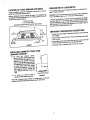
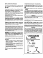
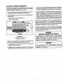
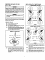
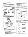
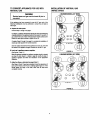
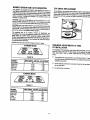
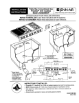
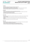
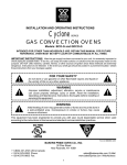
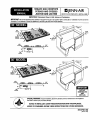
INSTALLATION
MANUAL
JGC7430
ANDcoorops
JGC7536
SEALED
GAS
I F_"JENN-AIR
JENN-AIR
CCG2423AND
CCG2523 [ 403WEST
IMPORTANT:
Dimensions
Shownin BothInchesandCentimeters.
IMPORTANT:
Besuretheappliancebeinginstalled
isequipped
forthegastobesupplied.
Refertoserialplateonunderside
of burner
boxforthis
information.
Donotattempt
toconvert
thisappliance
forusewitha gasotherthanthetypespecified.
30" MODEL
76.2 ¢m
__, _=_ = = '-_"-=--_
,Is._,o_
_L'__._._ ,
1%"
_ _
'-f
\\ _\
27._=n t.
! i"///
Z
/f"_YI/
\\
I _(
4.21 ¢rn
36" MODEL
329/_s"± V_e".-/S6'
_
82.71 cm
Er_
. Clearance I
s'_,
I_
D
4._m
_
_._A9"_
_
//
_50.96
I I
/
_ii_
_
cm
,
I
,_'-_',,.,,;,=----,i._ll.
,,L_.I
"="
\\IY
_/
P0rAI
IMPORTAN1
CUTOUT
DIMENSIONS
ARE
CRITICAL
canresultinserious
injury
orproperty
damage.
NOTICETO INSTALLER:LEAVETHESEINSTRUCTIONS
WITHTHEAPPUANCE.
NOTICETO CONSUMER:RETAINTHESEINSTRUCTIONS
FORFUTUREREFERENCE.
SPECIALWARNING:Improper
installation,
adjust
ment,
alteration,
service,
maintenance
oruseofappliance
8101 P401-60
(o8-ol-oo)
LOCATION
OFYOURJENN-AIR
APPUANCE
PREPARATION
OFCOUNTERTOP
Locatethisappliance
awayfromcombustible
materials
suchas window
curtains
andcombustible
walldecorations,
Minimumhorizontal
clearance
betweentheedgeoftheappliance
and
combustible
construction
extending
fromthecooking
surface
to18_(45.72
cm)abovethecooking
surface
is
Thecountertop
cutoutmustbe prepared
according
to theillustration
on
page1 oftheseinstructions.
1" (2.54cm)atrear
4" (10.16cm)atsides
(Dimensions
applyto both30"and36"widemodels)
* Jenn-AJr
Over-the-Range
microwave
m,ens(model
#M418andM438)
havebeenlistedbyUL for use overGasandElectric
Ranges.When
properly
installedata minimum
heightof 66 inches(167.64cm)fromthe
floortothetopofthemicrowave,
theclearance
tothecooking
surfaceat
i ..............
,
1.
,,jr
(2_4
ore)
-.-_; -_
___r/_
2" I
11._'
Min.
(_.81crn]
_`%',,.
I
-_
__.
thecenter
willbe 13-3/4itches(34.93cm).
1
"
---[
'18'
IMPORTANT
PREPARATION
SUGGESTIONS
',45.72,)_
.
4...__ _
(tO.t6cm)
FIGURE1
INSTALLING
CABINETRY
OVERYOUR
JENN-AIR
COOKTOP
A= 30" (76.2 cm) minimum vertical
clearance
between
cooking
surfaceand
construction
abovethe appliance,
This
clearancemaybe reducedto notless
than24inches(60.96cm)by protecting
theunderside
ofthecombustible
material
surfacewithnotlessthan1/4inch(.635
or metal cabinetab°vethe co°king!
cm) insulatingmillboardcoveredwith !
sheetmetalnot lessthan0.0122inch ,I,
CAUTION:
Cutout
dimensions
arecritical.
Dimensions
mustbemeasured
andcutaccurately
towithin..+.
1/16"(.159cm)toensureproper
fit.
___
B
__
thick*
J--[
B= 13" (33.02 crn) maximumdepth of
cabinets
installed
abovecooking
top.
FIGURE2
Avoiduseof cabinetsabovecooktopfor storagespaceto eliminate
associated
potentialhazards
suchasreaching
overopenflames.
I. damagefrom
Chamfer
chipping.
all exposededges ofdscorativelaminateto prevent
2. Radiuscornersof cutoutandfileto insuresmoothedgesandprevent
cemarcracking,
3. Roughedges,insidecornerswhich
havenotbeenrounded
andforced
fitscancontribute
tocracking
of thecountertop
laminate.
4. Countertop
mustbesupported
within3" (7.62cm)of cutoat.
INSTALLATION
OFAPPLIANCE
CONNECTING
APPLIANCE
TOGASSUPPLY
Theinstallation
of thisappliance
mustconform
withlocalcodesor,inthe
absenceof local codas,with the NationalFuel Gas Code,ANSI
Z223.1-LatestEdition,
or,inCanada,CAN/CGA-B149
Installation
Code,
latestEdition.
A TRAINEDSERVICEMAN
ORGASAPPLIANCE
INSTALLER
MUST
MAKETHEGASSUPPLYCONNECTION.Leaktastingoltheappliance
shall be conducted
by the installeraccordingto the instructions
given.
This appliance,when installed,must be electrically
groundedin
accordance
withlocalcodesor,intheabsence
of localcodes,
withthe
National
Electrical
CodeANSI/NFPA
No.70-latestEdition,
or,inCanada,
current
CSAStandard
C22.1Canadian
Electrical
Code,Part1.
Allsupplypiping,exceptas noted,shouldusecommon
National
Pipe
Thread(N.P.T.).Forall pipeconnections
usean approved
pipejoint
compound
rasistant
totheactionofLP gas.
1. IF NOOTHERAPPLIANCE
IS TO BEINSTALLEDBELOWTHIS
COOKTOP
Jointheappliance
pressure
regulator
supplied
withthisappliance
tothe
entrance
threads
oftheGasManifold.
Theappliance
regulator
ismarked
witha directional
arrowindicating
correct
direction
of gasflow.Ensure
the
appliance
regulator
is installedwiththearrowpointing
towardthegas
manifold
entrance.
Tightentheappliance
regulator
to20 to30 ft-lbsof
torque.
CAUTION:
Warranty
isvoidonJenn-Air
equipment
installed
otherthanas
I
recommended
bymanufacturer.
Thisappliance
is designed
for usewiththe appliance
gaspressure
I pipe
Never
tighten
tomore
than35ft-lbs
oftorque.
Alwaysuseanapproved
joint
compound
rasistant
totheaction
ofLPgas.
regulator
supplied
withthisappliance.
Itmustbeinstalled
inthegasway
aheadofthegasmanifold
entrance.
Itispreset
forusewithnatural
gasand
mustbe converted,
as described
onpage6, forusewithLPgas.(See
figures
10and11.)
Installtheappliance
initscounter
cutout.
Thisappliance
isdesigned
tooperateat a pressure
of 5 inches
ofwater
column
on natural
gasor,if converted
forusewithLPgas(propane
or
butane),
10inches
watercolumn.
Makesurethisappliance
issupplied
with
andadjusted
forthetypeofgasforwhichit isdesigned.
Installa manualshut-off
valvein anaccessible
location
in thegasline
aheadoftheappliance
pressure
regulator
andexternaltothis
appliaoce
for
thepurpose
ofturning
onorshutting
offgastotheappliance.
IMPORTANT
Makethegasconnection
totheinletof theappliance
pressure
regulator
with1/2"malepipethreads.
Thisappliance
wasadjusted
atthefactory
forusewithnatural
gas.If,atany
time,thisappliance
istobe usedwitha different
typeof gas,all ofthe
conversion
adjustments
described
onpages5 and7 mustbe madebya
qualified
service
technician
beforeattempting
tooperate
thecooktop
on
thatgas.Natural
gasshould
besupplied
totheappliance
pressure
regulator
ata linepressure
between
6 and14inches
ofwatercolumn
or,ifconverted
forIF'gas,between
11and14 inches,
WARNING:If the line pressuresupplyingthe appliancepressure
Makeadditional
pipeconnections
asnecessary
aheadoftheshut-off
valve
tothegassupply
source.
Assureallpipejointconnections
aregastight.
IMPORTANT
Applya non-corrosive
leakdetection
fluidtoalljointsandfittings
inthe
gasconnection
between
thesupplylineshut-off
valveandtherange.
Include
gasfittings
andjointsintherangeifconnections
weredisturbed
during
installation.
Checkforleaks!Bubbles
appearing
around
fittings
andconnections
willindicate
a leak.If a leakappears,
turnoffsupply
line
gasshut-off
valve,tighten
connections,
turnonthesupply
linegasshut
offvalve,andretestforleaks.Nevertestforgas leakswithan open
flame.
regulator
exceeds
14"W.C.(anygas),an external
regulator
mustbeI
installed
inthegaslineaheadoftheappliance
regulator
toreduce
theI
pressure
to nomorethan14"W.C. Failure
to do thiscanresultin
malfunction
anddamage
totheapplance.
ILLUSTRATIVE
GAS SUPPLY PIPING
(NO OTHER APPLIANCE BELOW COOKTOP)
Insurethisappliance
isadjusted
forthetypeofgassupplied
toitandthat
thegassupplypressure
totheappliance
regulator
iswithintheproper
pressure
range.
_
I
• If thisisa 36"widemodel,orif it isa 30"widemodelandnoother
applianceis to be installed
in the cabinetry
belowit, proceed
as
instructed
underparagraph
I.
I
(REAROFAPPLIANCE)
BURNER BOX
I
I I_
MANIFOLD
I_, _
ENTRANCE
_
APPLIANCE
WallOvenis
to beanda
installed
in cabinetry
proceed
as
• Electric
If thisisa
30"widemodel
Jenn-Alr
Modelb
Welow,
30XXX
orW131
instructed
underparagraph
II.
__
/ I
REGULATOR
PRESSURE
• Donotremove
protective
capfrompipestubatmanifold
entrance
until
_
ALLPIPEJOINTS
MANUAL
SHUTOFF
NOTE:In Canada,
gasutilization
codasprohibit
useofstreetelbows.
Use
standardpipeelbowsandmakemodifications
to theseinstructions
as
necessary.
readytojoingassupply
pipingtoappliance.
VALVE
.j..
_i
1/2 N.P.T.
|-ELBOW
3
FIGURE3
TOGAS
INLET
2. IF THISISA 30" WIDECOOKTOP
ANDAJENN-NR,MODEL
W30XXXORW131,ELECTRIC
WALLOVENISTOBEINSTALLED
BELOWTHISCOOKTOR
NOTE1:Thisappliance
anditsgasandelectrical
supply
sources
mustbe
installed
before
thewallovenisinstalled,
Seeillustration
(Electrical
Wiring
tnformahon
- page4;figure6)forrecommended
electrical
supply
source
(ovations.
NOTE2: Itmaybenecessary
toextend
gassupply
piping
forthisappliance
intoadjacent
under-counter
cabinetry
whenawallovenisinstalledbelow
thisappliance.
Joina 1/2"NPTpipeelbow(locally
available)
tothe malethreads
at the
manifold
entrance.Whenjoined,causetheopenthreads
of theelbowto
facetowardtheleftsideoftheappliance.
Installtheappliance
inkscounter
cutout.
Joina 1/2"NPTpipenipple
totheelbowusinga pipesection
ofsufficient
lengthtoextend,horizontally,
beyond
the leftsideof thewalloven.(To
accomplish
thisitmaybenecessary
toextend
thepipesection
intoadjacent
cabinetry.)Join additional1/2" NPT elbow(s)and pipe nipples,as
necessary,
to accomplish
thefollowing:
Jointhe outletof the appliancepressure
regulatorsuppliedwiththis
appliance
tothemalethreadsof the newlyinstalledgassupplypiping.
InstaU
theappliance
regulator
ina location
whichwillbeaccessible
beside
orbelowthewalloven.Insuretheappliance
regulator
is installed
withits
directional
arrowpointing
inthedirection
ofgasflow.Tightentheappliance
regulator
to20to30ft-lbsoftorque.
IMPORTANT
]
NevertJghtan
tomorethan35ft-lbsof torque.
Always
useanapproved
I
pipejointcompound
resistant
to theaction
ofLPgas.
]
Locate
andjoina manualshut-off
valveinanaccessible
location
inthegas
lineaheadoftheapplianceregulator
andexternal
totheappliance
forthe
purpose
ofturningonorshuttingoffgasto theappliance,
Makeadditional
pipeconnections
asnecessaryahead
oftheshut-off
valve
tothegassupplysource.Assureall pipejointconnections
aregastight,
IMPORTANT
Applya non-corrosive
leakdetection
fluidtoalljointsandfittings
inthe
gasconnection
between
thesupply
lineshut-offvalveandthe range,
include
gasfittings
andjointsintherangeifconnections
weredisturbed
duringinstallation.
Checkforleaks!Bubbles
appearing
aroundfittings
andconnections
willindicate
a leak.If aleakappears,
turnoffsupply
line
'gasshut-off
valve,tighten
connections,
turnonthesupplylinegasshut
Ioffvalve,and retestforleaks.Nevertestforgasleakswithan open
i flame.
ILLUSTRATNE
GASSUPPLY PIPING
(WALL
OVEN
INSTALLED
BELOW
30"COOKTOP)
j
7
_
=_'_EReox
(Rz,_oF_a
I
I _"¢"
lr,.N.p.,.
]
I t_="_ [ ALL
_PEao_xrs
__.
_N_
L- _ .,%._
,_FgCO_MA_
SZC'nU_
pROFILE OFCROSS
WALL OVEN
FIGURE4
Note,regarding
Figure4,
above:
• Forconvenience
in service
a groundjointunion(notshown:locally
available)
should
be included
in thepipingillustrated
infigure4, in
location
mostpracticed
fortheinstallation.
Generally,
a practical
iccatlor
isinthe_binet belowthisappliance,
nearthemanifold
entrance,
rathe
thaninan adjoiningcabinet.
• If the alternativepipingmethodshownin figure5 is selectedforthe
installation,
no groundjoint unionis required.(Theflexibleapplianc_
connector
illustrated
provides
theunionjointsnecessary
forservicing.
I
Whena dividing
wallis presentanda flexibleconnector
is usedit i=
recommended
for convenJanse,
in bethinstallation
and service,
th_
flexibleconnector,
itself,passthrough
thedividing
wall.Anyflexlbl
connector
usedwith thisappliance
mustsatisfyall requirement
statedinthetextaccompanying
figureS.
ALTERNATIVE
PIPINGMETHODS
TOCONNECT
APPUANCE
TOGASSUPPLY
A TRAINEDSERVICEMAN
ORGASAPPLIANCEINSTALLERMUST
MAKETHEGASSUPPLY
CONNECTION.LeakIasting
oftheappliance
shallbe conductedby the installeraccordingto the instruation8
given.
Unlessprohibited
bylocalcodesorordinances,
a newA.G.A.- Certified,
flexiblemetalapplianceconnector
maybeusedto connectthisappliance
to itsgassupply.Theconnector
musthavean internaldiameternotless
thannominal1/2" NPTpipeandbe nomorethan5 feetin length.A 1/2"
NPTx 1/2" flare unionadapteris requiredat eachendof the flexible
connector,
ff a flexibleconnector
is usedassurethat b_h theappliance
pressureregulatorand manualshut-offvalvearejoinedsolidlyto other
permanent
hardpiping(eithergassupply
ortheappliance
manifold)
soas
tobe physically
stationary.
Seaillustrations
below:
CAU11ON:
Donot_empt toattachtheflexible
connector
directly
toan
external
pipethread.Connection
requiresflareunionadapters.
IMPORTANT
Applya non-corrosive
leakdetection
fluidtoalljointsandfittingsinthe
gasconnection
betweenthesupplylineshut-offvalveandthe range.
Include
gasfittingsandjointsintherangeif connections
weredisturbed
duringinstallation.
CheckforleakalBubblesappearingaroundfittings
andconnectionswill
indicatealeak.
Ifaleakappears,
tumoffsuppiyline
gasshut-o_1
valve,tightenconnections,
turnonthesupldylinegasshut
offvalve,andretestfor leaks.Nevertestfor gasleakswith an open
flame.
PRESSURE
TESTING
ILLUSTRATIVE ALTERNATIVE PIPING
Theappliance
mustbe isolated
#orethegassupplypipingsystemby
thegassupplypipingsystemattest pressures
equalto or lessthan1/2
PSIG (3.5kPa).
I
I
t
e.-..-
.._
m
!
R
I
jCalt
I
I
NOAPPL.JANOE
THISCOOKTOP
MOUI/11_D
BELOW
_
_
Guut._
vz_
I
WALL
OVENMOUNTED
IN CABINETRY
BELOW
THIS COOK_OP
_-_NPTP_
_
II ] (_
_[!,ml supply
pipe)
FIGURE5
This appliance,as wall as its individualshut-offvalve, mustbe
disconnected
fromthegassupplypipingsystemduringany pressure
testingofthesystem
attestpressures
inexcess
of 1/2PSIG(3.5kPa).
closingits individual
manualshut-off
valveduringanypressure
testingof
Whencheckingapplianceregulatorfunction,makecertainpressureof
naturalgas supplyis between6 and14 inchesof watercolumnor,if
converted
forLPgas,between
11and14inches.
ELECTRICAL
WIRINGINFORMATION
Thisappliance
isequipped
witha grounded
typepowercord.Agrounded
outletmustbeprovided.
Itisrecommended,
forconvenience,
theoutletbe
located
(withreference
tofigure6) asinAor8, below:
A. If nootherappliance
istobeinstalledbelowthisappliance:
within
_ther
theshaded
areaorthecrosshatched
areashown
infigure6.
B. If a ModelW30XXXorW131electric
ovenistobeinstalled
below
this
appliance,
either:
1. withintheorosshatched
areaoffigure6,or,
2. withinanadjacent
cabinet,
I
91.44crn
I
cAeiNs'r
BO'r'rou
T
FIGURE6
DimenalonA:
W30XXX:5-1/2"(13.97cm)
Wt31:4"(tO.16cm)
If a wallovenisto beinstalledbelowthisapplianceandthecounterunit's
outletis tobe mounted
withinthecrosshatched
areaof figure6:
1. The cabinet'slowerfrontpanel,belowthe oven,must be made
removable
foraccessto theoutlet.
2. A
clearanceholefor
the powercord'splug(1-1/4"(3.18cm)dia
is
recommended)
mustbeprovided
throughtheoven'sfloorsupportshelf
and,if necessary,
throughtheslatssupporting
theshelf.Theclearance
holeshould
belocated
asnearaspractical
totherearoftheshelfand
(iftheovenismodel
W30XXX)
asnearaspractical
totheleftrearcomer.
3. WhenmodelW3OXXX
ismounted
belowthisappliance,
andifthepower
outletforthisappliance
is tobelocated
inthecrosshatched
areaof
figure6, it is recommended
thepowercordbe routedthroughthe
externalvertical
clearance
channel
at the left rearof theoven.The
channel's
crosssection
isapproximately
4.2" x 2.25"(10.7x 5.7cm),
extending
thefull
heightoftheoven.(ModelW131provides
a similar,
butlarger,
vetticalchannel
nearthecenter
ofthemainbackoftheoven.)
Iftheoutletis tobe mounted
ineithera leftorrightadjacent
cabinet,
a
clearance
hole,asdescribed
above,mustbeprovided
inthedividing
wall
betweenthecabinets.
Figure4; page3, illustrates
a typical(leftside)
is convenient
in thisleftwallorinthecorresponding
rightwall.
dividing
wall.Theclearance
hole(notshowninfigure4) canbelocatedas
In planning
anyinstallation,
notethat thefreelengthofthisappliance's
centeroftherearwalloftheburnerbox,whenviewedfromthefrontofthe
powercord,extending
unit,isapproximately
46"
beyond
(117
acm).
point3-3/4"(9.53cm)leftofthenominal
WARNING
ELECTRICAL GROUNDING INSTRUCTIONS
THIS APPLIANCEIS EQUIPPEDWITH A THREE PRONG
GROUNDING
PLUGFOR YOURPROTECTION
AGAINSTSHOCK
HAZARDAND SHOULDBE PLUGGEDDIRECTLYINTO A
PROPERLYGROUNDEDRECEPTACLE.DO NOT CUT OR
REMOVE
THEGROUNDING
PRONGFROMTHISPLUG.
i
WARNING
I
]!
THIS APPUANCE MUST BE DISCONNECTEDFROM ITS]
ELECTRICAL
SUPPLYAT THE WALL RECEPTACLE
BEFORE]
SERVICING
THEAPPLIANCE.
CONVERTING
APPLIANCE
FORUSE
INSTALLATION
OFLP ORIFICE
SPUDS
WITH LP GAS
4 BURNER MODEL (30" WIDE)
WARNING
Propane
conversion
isto beperformed
bya JENN-AIR
AUTHORIZED
SERVICER(or otherqualifiedagency)in accordance
withthe
manufacturer's
instructions
and all codesandrequirements
of the
authority
having
jurisdiction.
Failure
tofollow
instructions
could
resultin
serious
injury
orproperty
damage.
Thequalified
agency
performing
this
workassumes
responsibility
forthisconversion.
Electrical
power
andgasmust
beturned
offprior
to
conversion. WARNING
I _
O (_)
convert
itforusewithLPgas(propane
orbutane),eachofthefollowing
modifications
mustbeperformed:
A. Replaceallorificespuds
Step1: Remove
thegratesandburner
heads.
Thisappliance
w
asadjusted
at
thefactory
Step2: Remove
aluminum
venturi
tube.forusewithnaturalgas.To
_T _Z19-,O-O
_
OFIGURE
(_ 8
Step3: Trima smallpieceofmasking
tapetothesizeofa dimeand
a_fixitovertheendofa 5/16"nutdriver.
Step4: Firmlypressthenutdriverovertheorificespud(figure7)and
loosenspudby turningcounterclockwise.
Carefully
lift nut
driveroutofburner
throat.Odficespudshould
becaptured
in
therecess.Repeatthisstepforeachburner.
5 BURNER MODEL (36"WIDE)
_
/ ,_--J.___\
f..l---._-__
/,--"'_--_
REMOVAL OF ORIRCE SPUD
o
FIGURE9
FIGURE7
Step6: Withthe masking
tapestillin placeintherecessof thenut
driver,pressanLPorificespudintotherecesssothat it is
snugly
captured.
Step5: LocatetheLPorificespudpackettapedtotheundersideoftheStep7: Carefullyinstalltheorificespudintheappropriatebumerthroa
byturningclockwise
totighten.
Tighten
toa torqueof15to20
burnerbox.Thespuds
havesmallnumbers
stamped
on the
inch-lbs.
side.Thisnumbercodestheorificediameter
anditscorrect
burnerlocation.
Thefollowing
illustrations
showcorrect
LP
Step8: Replacecylindrical
aluminum
venturitubes.Replaceburner
orificespudlocation
for 4 burnerand5 burnermodels,
headsandgrates.Indexeachgratetoitsburner
pan.
respectively.
Step9: Savetheorifices
removed
fromtheappliance
forfutureuse.
B. Invertmp In appliancepresaureregulator
(Seefigures10and11.)
Withtheappliance
installed,
theapplience
regulator
shouldbelocated
3. Inserta slender,thin-blade
screwdriver
intotherecessatcenterof
valvesternendengagebladewithslotin adjusting
screw.
asshownin figure3or4.Identifythetypeof appliance
regulator
onthe
unitandfollowtheinstructions
intheappropriate
illustration.
4. Turncenterstemadjusting
screwto setflamesize.
... clockwise
toreduce
... counterclockwise
toincrease
5. Replacecontrolknobwhenadjustment
is completed.
CONVERSION OF MAX1TROLAPPLIANCE
PRESSURE
REGULATOR
APPLY
DO_IWN_
RN_R
PRESSURE
AT
DISC
ED6ESTO
CO_IVERTE
¢/#
PiN
,j.
J
APPLY
SI_'A_
fJqqPTORB_OVE
RN
CL_j RK_ICAP
Proper
adjustment
willproduce
a stable,steadyblueflameof minimum
size.Thefinaladjustment
shouldbecheckedbyturningknobfromhighto
lOWsever_timeswithout
extinguishing
theflame.
_w.,v
Thisadjustment,
atlowsetting,
willautomaticaJly
provide
theproper
flame
_
sizeatmediumsetting.
SIZE
TO INCREASEFLAME
CLOCk3NISE
REDUCE
FLAMESIZE
_
FIGURE10
COUNTERCLOCk3NISE
..""'-1 [----_ ..WLVE
CONVERSION
PRESSURE
OFHARPER-WYMAN
REGULAToRAPPUANCE
_
:_:,
_u
After Conversion
StepsA, B and C havebeencornpleted,
checkthe
appearance
ofeachburner's
flameattheHiandLosettingsagainstfigure
13.If theflamesappeartoo (argeor toosmall,revieweachstepto make
FIGURE12
sureit wascompleted
correctly.
_
Natural Setting
_LP
FIGURE11
FLAME
APPEARANCE
ATHIANDLO
,Setting
(Seefigure12.)
Thisappliance
isshipped
fromthefactory
withlowandmedium
flame
C, LOW
FlameAdjustment
settings
adjustedfor usewithnatura)gas.If furtheradjustment
is
necessary,
orto readjust
forusewithLP,proceed
asfollows:
=_"
L,
_
,
o,,, ,,,,.,
(_ _
o,
1, Lightburner
andsetcontrol
knowforlowflame.
2. Removecontrol
knobfromvalvestem.
_,["/
"_
HI
CAUTION:
NEVERUSEAMETALBLADE
TOPRYKNOBOFF.IF
KNOBCANNOT
BEEASILYREMOVED,
TUCKTHEFOLDSOFA
CLOTHDISHTOWEL
UNDERTHEKNOBANDPULLTHETOWEL
UPWARD
WITHSTEADY,
EVENPRESSURE.
ow
FIGURE13
TOCONVERT
APPLIANCE
FORUSEWITH
NATURAL
GAS
WARNING
Electrical
power
andgasmust
beturned
offprior
to
conversion.
INSTALLATION
OFNATURAL
GAS
ORIFICE
SPUDS
I
4 BURNER MODEL
J
If this appliancehasbeenconverted
forusewithLPgas,eachofthe
following
modifications
mustbe performed
toconverttheunitbackto
natural
gas.
A. Replaceallorificespuds
Perform
Steps1 through
4 onpage5.
ForStep5:Locate
thecolored
brassnatural
gasorifice
spuds
thatwere
originally
installed
inthis
beforeitsconversion
foruse
with
LP
gas.Observe
thecolor
oappliance
feachofthespuds
andnotethe
correct
burner
(_
Complete
Steps6spud
through
9 onpage
5 tocomplete
the installation
of
location
foreach
as shown
infigures
14and15.
natural
gasmainspudsintheircorrectlocations.
Savetheorifices
removed
fromtheappliance
forfutureuse.Theywill
be needed
if thisappliance
isagainconverted
forusewithLPgas.
B. Invertcapin applianceprassumregulator.
(Seefigures10and11.)
Withtheappliance
installed
theappliance
regulator
should
belocated
as shownin eitherfigure3 or figure4 (page3). Identify
thetypeof
applianceregulator
and followthe instructions
in the appropriate
illustration.
C. Adjustlowflameasinstructed
on page6 itemC.
AfterStepsA,BandChavebeencompleted,
checktheappearance
of
eachburner'sflameat theHi andLo settingsagainstfigure13.If the
flamesappeartoo largeor too small, makesure all stepswere
completed
correctly.
_
_
(_
(_ (_
,,RT
_2_,,-,9_-.0
//
FIGURE14
5 BURNER MODEL (36"WIDE)
k
_RT t_21W-993-_
FIGURE15
(_
BURNERIGNITIONANDAUTO-REIGNITION
TOPGRATEREPLACEMENT
Thisappliance
is equipped
forelectronic
auto-raignition
by meansof a
sparkigniterlocated
attherearofeachburner.
Theburners
aredesigned
tolightatanyvaJve
rotation
thatadmitssufficient
gesflowtosupport
aflame
andtoautomatically
relightfollowing
a lessofflameduetoa draftorother
adversecondition.Thisfeatureis providedas a convenience
andis not
intendedasa safetyfeature.
Thetopgrates
onthiscooktop
haveunderside
projection
lugsdesigned
nestinmatching
depressions
inthesplllnver
trays.Duringgratepleceme
elwayspesition
gratestomakethisengagement.
Correct
indexing
ofgrat_
aboveburnerportswill preserve
thegrates'appearance
and helpassut
longlife.
CAUTION:Neverusea metalbladeto pryoff a controlknob.If a knob
cannotbe easilyremovedtuckthefoldsof a clothdishtowelunderand
aroundtheknobandpullthetowelupwardwithsteadyevenpressure.
CAUTION:
Nevercovercontrolknobsor surrounding
controlsurfacewith
utensils,
towels,orotherobjects.Neverobstruct
freeairpassagepastthe
controlknobs.Theknobopeningshavebeensizedtoproperlycontrolair
entrytothe interior
oftheappliance
duringoperation.
This appliancehas no air shutters.Primaryair adjustments
are
unnecessary.
Theburners
aredesigned
toprovide
optimum
aer_ionforall
gaseswithoutair shutters.
Whenoperatingproperty,
burnersshould
produce
clearly
defined,evenblueflames.If theflameshaveyellow
tipsor
arehazyandotherwise
appeartohaveinsufficient
air,obtaintheservices
ofa qualified
service
technician.
Specified
inputr=esare asshowninfigures16and17,below.
REQUIREDADJUSTMENTSATTIME
OF INSTALLATION
4 BURNER
MODEL
E_ _
absenceof lecelcodes,withthe latesteditionof theNationalFuelGas
CodeANSI Z223.1USA or currentCAN/CGA-Bf49INSTALLATION
Theinstail=ienofthisappliancemustconform
CODE.
withIo_ codes,orinthe
FIGURE16
BURNER
LOCATION
RightFront
RightRear
LeftFront
LeftRear
INPUTRATES- NATURAL
GAS(BTU/HR)
Hi
Lo
12,000
1,500
9,100
1,050
6,500
830
10,500
1,500
5BURNER
MODEL
FIGURE17
BURNER
LOCATION
RightFront
RightRear
Center
LeftFront
LeftRear
INPUTRATES. NATURAL
GAS(BTU/I'IR)
Hi
Lo
12,000
9,100
6,500
9,100
10,500
1,5_
1,050
830
1,050
1,500
f0
[]
Thisappliance
wasmanufactured
forusewithNaturalGas.If LPgas
isthefuelofchoice,
followtheconversion
toLPprocedure
foundinthe
installation
instructions.
[]
Testallexternal
connections
forgasleaks.Nevertestforgasleaks
withanopenflame.
[]
Testallelectrical
connections.