1
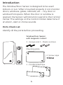
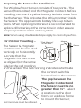
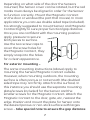
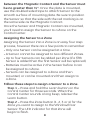
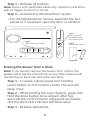
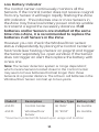
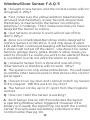
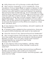
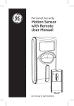
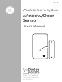
45131
Wireless Alarm System
Window/Door
Sensor
User’s Manual
Choice
ALERT™
™
Control all Sensors
& accessories from
one location
Table of Contents
Important Safeguards
4
Introduction
5
Installation
6
Assigning a Sensor to a Zone
8
Erasing a Sensor from a Zone
9
Testing a Sensor or your system
10
10-11
Low battery indicator
11
Battery warnings
12-13
F.A.Q.'S
14
FCC Warning
Before connecting or operating the Window/Door
Sensor, please read these instructions carefully and
save this manual for future reference.
Congratulations
The GE Choice Alert™ Wireless Alarm System is one
of the most affordable and expandable wireless
alarm systems available. You’ll discover the system
offers many features typically found in custom
installed Alarm systems.
The Choice Alert system is reliable and easy-to-use.
With Choice Alert you can select from a line of Sensors
and Accessories; start small and expand as you
need, or create a system that meets all your needs.
The Choice Alert System is protected by Priority
Code Selection technology which provides increased
security and trouble-free wireless connections. It
also guarantees the Control Center will only respond
to signals from your Sensor in and around your home,
and prevents anyone from tampering with your
system.
The user manual explains in simple steps how to
install, use and care for your new Choice Alert
Window/Door Sensor.
Important safeguards
PreCautions
1. Do not attempt to disassemble the Window/Door
Sensor, unless described in the user’s manual. There
are no user serviceable parts.
2. Handle with Care – Avoid striking or shaking.
Improper use or storage could damage the Window/
Door Sensor. Modifying or tampering the device or its
internal components can cause a malfunction and
void the Window/Door Sensor’s warranty.
3. If you feel the Window/Door Sensor any part of
the Choice Alert system is not operating correctly or
as described, please contact Customer Service for
assistance (1-800-654-8483).
Introduction
The Window/Door Sensor is designed to be used
indoors or out. When mounted properly it can monitor
doors, windows, gates, cabinets, etc. – any door or
window that opens. When the door or window is
opened, the Sensor will transmit a signal to the Control
Center. The settings on the Control Center determine if
an alarm, alert or chime sounds
Parts Check List
Identify all the parts before proceeding.
Window/Door Sensor
with magnetic contact
2 - Screws and 2 - Plastic anchors
Mounting plate
2- Screw caps
2 - Double sided tape
Preparing the Sensor for Installation
The Window/Door Sensor consists of two parts – The
Sensor (Transmitter) and the Magnetic Contact. Before
installing, remove the yellow battery isolation tape from
the the Sensor. This activates the Lithium battery inside
the Sensor. The approximate battery life is up to two
years. When replacing batteries it is recommended to
replace all batteries at the same time in order ensure
proper operation of the entire system.
Note: When using doublesided tape apply to clean dry surface.
For Interior Mounting –
"Red Marking"
on the side
Magnet
Sensor
The Sensor & Magnetic
Contact can be mounted
vertically or horizontally
but note that the
Magnetic Contact must
be aligned (on the same
side) as the red marking
on the Sensor. The red marking indicates which side
the contact switch is
located inside the Sensor.
Red markings must be alligned.
The gap between the
Magnetic Contact and
the Sensor must be no
greater than ½”. Select
a position on the door
frame or window frame
to mount the Sensor;
Depending on what side of the door the Sensors
mounted, the Sensor cover can be rotated, but the red
marks must always be aligned in order for the Sensor
to function correctly. Mount the Magnetic Contact
on the door or window (the part that moves). In most
applications you can use double sided tape (included).
It is strongly suggested to mount Sensor and Magnetic
Contract lightly to sure proper function/gap distance.
Once you are confident with the mounting position
apply pressure to secure
both pieces to surface.
Use the two screw caps to
cover the screw holes for
the Magnetic Contact, they
simply snap into the holes
for a clean appearance.
For exterior mounting –
The same mounting instructions (above) apply to
mounting the Sensor/Magnetic Contact outside.
However, when mounting outdoors, the mounting
surface is often porous or not smooth (the doubled
sided tape may not firmly attach to the surface). In
this instance you should use the separate mounting
plate/screws (included) for the Sensor and the
smaller screws for the Magnetic Contact. Attach the
Magnetic Contact to the door, gate, etc, nearest the
edge. Position and mount the plate for Sensor onto
the desired porous or non-stick surface with larges
screw – take special note to ensure the gap distance
between the Magnetic Contact and the Sensor must
be no greater than ½”. Once the plate is mounted,
use the doubled sided tape to attach Sensor to the
smooth surface of mounting plate. Be sure to position
the Sensor so that the side with the red marking is on
the same side as the Magnetic Contact.
Once the Sensor and Magnetic Contact are mounted,
you’ll need to assign the Sensor to a Zone on the
Control Center.
Assigning the Sensor to a Zone
Assigning the Sensor into a Zone is an easy four step
process, however there are a few points to remember
- Only one Sensor can be assigned at a time.
- A Sensor cannot be assigned to two different Zones.
- Up to four Sensors can be added per Zone (if a fifth Sensor is added then the first Sensor will be replaced.)
- Batteries must be active in the Sensor before it can be assigned to a Zone.
- Sensors can be assigned to a Zone and then mounted, or can be mounted and then assign to
a Zone.
Follow these steps to assign a Sensor to a Zone.
Step 1 – Press and hold the Learn button on the Control Center for three seconds. When the
Control Center sounds a long beep, release the Learn button.
Step 2 – Press the Zone button (1, 2, 3 or 4) for the Zone you want to assign to the Window/Door Sensor. The LED indicator for that Zone will
begin to flash.
Step 3 – Release all buttons.
Note: Zone 4 is for dedicated alerts only. Sensors in this Zone
will not trigger an alarm or chime.
Step 4 – Activate the Window/Door Sensor
- For the Window/Door Sensor, separate the two pieces or if mounted, open the door or window.
Step 1
Press and hold
the Learn button
for three seconds
Step 2
Select the Zone number
Input DC 12V
-
+
Mute
Step 3
Activate the Sensor
Learn
1 2 3 4
Arm
Alert
Chime
1
2
3
4
Armed Power
Off
Zone
Erasing the Sensor from a Zone
Note: If you need to remove the Sensor from a Zone, the
system will erase the entire Zone, so any other Sensors will
need to be put back into that particular Zone.
Step 1 - To erase a Zone, press and hold the
Learn button on the Control Center. The unit will beep once.
Step 2 - While holding the Learn button, press and
hold the Zone button to be erased. After five seconds the Control Center will sound two beeps and the Zone LED indicator will flash twice.
Step 3 - Release all buttons.
Note: The Zone/Sensor cannot be erased if:
- The Zone has been triggered for an Alert or alarm. The Sensor/Zone must be reset.
- There is loss of signal from the Sensor to the Control Center (such as low battery, or Sensor is out of range).
- The system is armed.
The Control Center will sound three beeps to indicate it could
not erase the Zone.
Testing a Sensor or your system
Once all the Sensors have been assigned to Zones
in the Control Center you can now test your system.
Ensure the Control Center can receive the signal
from the intended location of the Sensor before
permanently mounting a Sensor.
Step 1 - Unplug AC adapter and remove batteries from the Control Center.
Step 2 - Press and hold the ‘Mute’ button and plug the AC adapter back into the Control Center. When all the LED indicators turn on, release the Mute button. The Control Center is now in Test Mode and any Sensor can now be tested in any Zone.
Step 3 - Set the Notification Mode to ‘Alert’ position and begin activating Sensors one at a time.
Note: The sensor has a LED that flashes to show when the
sensor has triggered and transmitted to the Control Center.
Step 4 - When testing is complete, unplug the AC
adapter, then plug the AC adapter back in and reinstall batteries. This returns the Control Center
to standard operation mode.
Note: The Control Center will automatically return to standard
operation mode after 5 hours.
10
Low Battery Indicator
The Control Center continuously monitors all the
Sensors. If the Control Center does not receive a signal
from any Sensor it will begin rapidly flashing the Zone
LED indicator . This indicates one or more Sensors in
the Zone may have low battery power and are unable
to transmit a signal the necessary distance. If all
batteries and/or Sensors are installed at the same
time into a Zone, it is recommended to replace the
batteries in all Sensors in the Zone.
However you can check the Window/Door sensor
status independently by placing the Control Center in
Test mode (see Testing a Sensor on page 9) and trigger
the Sensor separately (i.e. open window). If the Sensor
does not trigger an alert then replace the battery with
a new one.
Note: The Sensor detection system is ‘range dependant’,
which means Sensors located closer to the Control Center
may seem to have batteries that last longer than those
Sensors at a greater distance. The Lithium cell batteries in the
Window/Door Sensor can last up to two years.
Model #
Description
Battery Type Battery Life*
45129
Control Center
(4) “AAA”
45131
24 months
Window/Door
(1) “2032”
24 months
Sensor
*maximum potential life based upon usage and location
11
Window/Door Sensor F.A.Q.’S
Q. I bought a new Sensor and the Control Center will not
recognize it. Why?
A. First, make sure the yellow isolation tape has been
removed and the battery is new. Second, ensure that
the battery is inserted into the Sensor according to
polarity(+/-) markings. Third, make sure that you have
assigned the Sensor to a Zone.
Q. I put Sensors on Zone 4 and it will not set off the
alarm. Why?
A. Zone 4 is a Dedicated Alert Zone and is designed to
monitor Sensors in this Zone. It will only issue an alert
(LED will flash, continuous beeping will be heard). Sensors
in Zone 4 will not set off the alarm. Use Zone 4 for water
Sensors, garage doors, gates, sheds or other areas you
want to monitor (i.e. areas you want to be alerted if there
is a problem, but do not want the alarm to sound).
Q. I erased a Sensor from a Zone and now all of my
other Sensors in that Zone will not work. Why?
A. The system can only erase entire Zones. You will need
to add the other Sensors back in that Zone to the control
panel again.
Q. I have trim on my door and I cannot match my Sensor
to the magnet. Will this work on my door?
A. The Sensor can be up to ½” apart from the magnetic
contact.
Q. How can I tell if the Sensor is working?
A. Each Sensor has an LED that indicates the Sensor
is operating (flashes when triggered). However if the
battery is to weak, the signal may not reach the Control
Center. This will cause low battery indication on the
Control Center (See pg 10).
12
Q. Why does one of my Zones continually flash?
A. This can be caused by 1 of 2 conditions. First
condition, if it is a rapid flash it means a Sensor in the
Zone has a low battery. If more than one Sensor is in
a Zone, you will need to test each Sensor by putting
the unit into test mode (see pg. 10 of manual). It may
also be that a Sensor is out of range and cannot make
contact with the Control Center. If this is the case, you
may need to move the Control Center closer or use a
Signal Repeater. The Second condition, if it is a slow
flash, one of the Sensors is triggered. Check all Sensors
to ensure the Sensors in the Zone are reset (i.e. close
door, window, etc).
Q. If one Sensor has a low battery, should I replace all
of the batteries?
A. If Sensors were added at the same time, chances
are good all the batteries will need to be replaced.
Q. How do I know if any Sensors have low batteries?
A. The Control Center will indicate if any Sensor does
not have sufficient power to transmit a status signal
(battery is low). You can also check each Sensor
independently by using the Test Mode
(see pg.10 in manual).
Q. If one Sensor has a low battery, will the other
Sensors in the Zone (or other Zones) continue to
operate?
A. Yes, as long as the other Sensors have sufficient
battery power, they will continue to transmit
information to the Control Center and the system will
operate normally.
13
FCC Warning
Any unauthorized changes or modifications to the equipment
would void the user’s warranty and may conflict with both
state and federal laws. The Choice Alert system complies with
part 15 of the FCC rules. Operation is subject to the following
conditions:
1) The Choice Alert system may not cause
harmful interference.
2) The Choice Alert system may accept any interference
received including interference that may cause
undesired operation.
NOTE: This equipment has been tested and found to
comply with the limits for a Class B digital device, pursuant to
Part 15 of the FCC Rules. These limits are designed to provide
reasonable protection against harmful interference in a
residential installation. This equipment generates, uses and
can radiate radio frequency energy and, if not installed and
used in accordance with the instructions, may cause harmful
interference to radio communications. However, there is no
guarantee that interference will not occur in a particular
installation. If this equipment does cause harmful
interference to radio or television reception, which can be
determined by turning the equipment off and on, the user is
encouraged to try to correct the interference by one or more
of the following measures:
– Reorient or relocate the receiving antenna.
– Increase the separation between the equipment
and receiver.
– Connect the equipment into an outlet on a circuit
different from that to which the receiver
is connected.
– Consult the dealer or an
experienced radio/TV technician for help
14
WARNING
Limitations of Alarm Products
This product should be tested periodically to make sure
it is working properly. The product, if used properly, may
reduce the risk of burglary, robbery, or other adverse events.
However, JASCO is not an insurer, this product is neither
insurance nor a guarantee that such an event will be
prevented, and users should protect themselves with proper
insurance. JASCO makes no representation that this product
cannot be compromised or circumvented, that it will provide
an adequate warning, or that it will prevent any personal
injuries, property damage, or other losses. Like any alarm
product, including expensive commercial systems, it may be
bypassed, it is subject to compromise, and it may fail to warn
for a variety of reasons, including, but not limited to: improper
installation or positioning; improper maintenance; tampering;
dead or improperly installed batteries; sensing limitations;
component failures; receivers; for infrared products,
intrusions may be outside of a product’s designed range and
certain environmental conditions may impact performance
and audible alarm signals may be outside of hearing range,
muted by doors, walls, and floors, unheard by deep sleepers
or the hearing-impaired, or overwhelmed by other sounds.
Risk of personal injury
- Prolonged exposure to alarm
siren may cause permanent
hearing loss
Battery Warning!
- Remove batteries before storing
the Alarm for extended periods
- Batteries may leak harmful liquids or ignitable materials or explode causing injury and product damage
- Do not mix old and new or other battery types
- Replace all batteries at the same time
- Replace fully discharged batteries immediately
15
is a trademark of the General
Electric Company and is used under
license to Jasco Products Company
LLC, 10 E. Memorial Road,
Oklahoma City, OK 73114.
This Jasco product comes with a
1 year limited warranty. Visit
www.jascoproducts.com for details.
45131-1
01/09/08