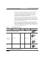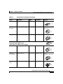
1
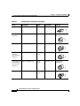
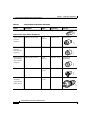
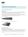
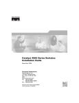
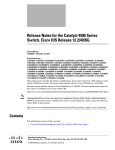
C H A P T E R
2
Preparing for Installation
Warning
This unit is intended for installation in restricted access areas. A restricted
access area can be accessed only through the use of a special tool, lock and
key, or other means of security. Statement 1017
Warning
Only trained and qualified personnel should be allowed to install, replace, or
service this equipment. Statement 1030
Warning
This equipment must be grounded. Never defeat the ground conductor or
operate the equipment in the absence of a suitably installed ground conductor.
Contact the appropriate electrical inspection authority or an electrician if you
are uncertain that suitable grounding is available. Statement 1024
Warning
Class 1 laser product. Statement 1008
Catalyst 4500 Series Switches Installation Guide
78-14409-08
2-1
Chapter 2
Preparing for Installation
Electrostatic Discharge
If you will be using your switch as a PoE source, the following warning applies:
Warning
Voltages that present a shock hazard can exist on inline power circuits if
interconnections are made by using uninsulated exposed metal contacts,
conductors, or terminals. Avoid using such interconnection methods unless the
exposed metal parts are in a restricted access location and users and service
people who are authorized to access the location are made aware of the hazard.
A restricted access area can be accessed only through the use of a special tool,
lock and key, or other means of security. Statement 1072
This chapter describes how to prepare your site for the installation of the switch.
The information is presented in these sections:
Note
•
Electrostatic Discharge, page 2-2
•
Site Power Requirements and Heat Dissipation, page 2-4
•
Power Connection Guidelines for AC-Powered Systems, page 2-5
•
Site-Planning Checklist, page 2-16
See the Site-Planning Checklist at the end of this chapter to help ensure that you
complete all site-planning activities before you install the switch.
Electrostatic Discharge
Electrostatic discharge is common on Category 5E and Category 6 cabling
systems.
Category 5E and Category 6 cables have higher capacitance than Category 5
cables. As a result, Category 5E and Category 6 cables can store higher voltages
than Category 5 cables and are more prone to damaging networking equipment if
a differential discharge event occur.
Unshielded twisted-pair cables can store high voltages. When these charged
cables are connected to networking equipment, energy is discharged into the
networking equipment; this is known as electrostatic discharge (ESD).
Networking equipment is commonly designed and tested to withstand common
mode ESD events of up to 2000 V. The design for the common mode event is
based on the expectation that the discharge is delivered to all pins of a port at once.
Catalyst 4500 Series Switches Installation Guide
2-2
78-14409-08
Chapter 2
Preparing for Installation
Electrostatic Discharge
Sometimes, voltage is discharged to some of the pins of the connector and not
others, or to some pins on the connector before others. This is known as a
differential discharge event, which can damage the networking equipment being
connected.
You can take the following measures to prevent ESD cable damage:
•
Ground the cable before connecting the networking equipment. You can
create a grounding cable using an RJ-45 patch cable by doing the following:
– Bare the wires on one end
– Connect the wires to a suitable and safe earth ground
– Connect the RJ-45 cable to a female RJ-45 connector
•
Briefly connect all cables to the grounded cable before connecting to
networking equipment.
•
Leave cables from the networking equipment in the distribution closet
connected to ports at user desktops. After you make connections on either
side of the cable to networking equipment, the cable will not build up charge.
Preventing Electrostatic Discharge Damage
Electrostatic discharge (ESD) damage, which can occur when electronic cards or
components are improperly handled, results in complete or intermittent failures.
Port adapters and processor modules consist of printed circuit boards that are
fixed in metal carriers. Electromagnetic interference (EMI) shielding and
connectors are integral components of the carrier. Although the metal carrier
helps to protect the board from ESD, use a preventive antistatic strap during
handling.
Following are guidelines for preventing ESD damage:
•
Always use an ESD wrist or ankle strap and ensure that it makes good skin
contact.
•
Connect the equipment end of the strap to an unfinished chassis surface.
•
When installing a component, use any available ejector levers or captive
installation screws toproperly seat the bus connectors in the backplane or
midplane. These devices prevent accidentalremoval, provide proper
grounding for the system, and help to ensure that bus connectors areproperly
seated.
Catalyst 4500 Series Switches Installation Guide
78-14409-08
2-3
Chapter 2
Preparing for Installation
Site Power Requirements and Heat Dissipation
Caution
•
When removing a component, use any available ejector levers or captive
installation screws to release the bus connectors from the backplane or
midplane.
•
Handle carriers by available handles or edges only; avoid touching the printed
circuit boards or connectors.
•
Place a removed component board-side-up on an antistatic surface or in a
static shielding container. If you plan to return the component to the factory,
immediately place it in a static shielding container.
•
Avoid contact between the printed circuit boards and clothing. The wrist strap
only protects components from ESD voltages on the body; ESD voltages on
clothing can still cause damage.
•
Never attempt to remove the printed circuit board from the metal carrier.
For safety, periodically check the resistance value of the antistatic strap. The
measurement should be between 1 and 10 megohm (Mohm).
Site Power Requirements and Heat Dissipation
This section provides module power requirements and heat dissipation
specifications for the Catalyst 4500 series switches. You should verify site power
before you install the switch.
For more information about power management and planning, refer to the
“Environmental Monitoring and Power Management” chapter in the Catalyst
4500 Series Switch Cisco IOS Software Configuration Guide version appropriate
for your software.
Knowing the power requirements is useful for planning the power distribution
system needed to support the switches. You should consider the heat dissipation
specifications when estimating the air-conditioning requirements for an
installation. For all Catalyst 4500 series switches, supervisor engines, and
switching modules in AC or DC environments see the Catalyst 4500 Series
Module Installation Guide at:
http://www.cisco.com/univercd/cc/td/doc/product/lan/cat4000/hw_doc/mod_inst
/0aspecs.htm#wp1012188.
Catalyst 4500 Series Switches Installation Guide
2-4
78-14409-08
Chapter 2
Preparing for Installation
Power Connection Guidelines for AC-Powered Systems
Power Connection Guidelines for AC-Powered
Systems
This section provides guidelines for connecting the Catalyst 4500 series switch
AC power supplies to the site power source. Basic guidelines include the
following:
•
Make sure each chassis power supply has its own dedicated branch circuit.
•
Size the circuits according to local and national codes.
•
If you are using a 200/240 VAC power source in North America, use a
two-pole circuit breaker to protect the circuit.
•
Place the source AC outlet within 6 feet (1.8 meters) of the system and make
sure it is easily accessible.
•
Make sure the AC power receptacles used to plug in the chassis are the
grounding type. The grounding conductors that connect to the receptacles
should connect to protective earth ground at the service equipment.
Four types of AC-input power supplies are available:
•
1000 W—Table 2-1 lists the AC-input power cord options, specifications,
Cisco part numbers, and shows the different styles of 1000 W AC-input
power cord wall plugs that are available for North America and international
locations as well as the appliance coupler that is attached to the power supply
end of the power cord.
•
1300 W—Table 2-1 lists the AC-input power cord options, specifications,
and Cisco product numbers, and shows the different styles of 1300 W
AC-input power cord wall plugs that are available for North America or
various international locations as well as the appliance coupler that is
attached to the power supply end of the power cord.
Note
For North America, the power cord plug types and appliance couplers
on the power supplies are different for the 1000 W power supplies and
the 1300 W power supplies; for other countries, the plugs shown are
the same for the 1000 W and 1300 W power supplies.
Catalyst 4500 Series Switches Installation Guide
78-14409-08
2-5
Chapter 2
Preparing for Installation
Power Connection Guidelines for AC-Powered Systems
•
1400 W—Table 2-1 lists the AC-input power cord options, specifications,
and Cisco product numbers, and shows the different styles of 1400 W
AC-input power cord wall plugs that are available for North America or
various international locations as well as the appliance coupler that is
attached to the power supply end of the power cord.
•
2800 W—Table 2-1 lists the AC-input power cord options, specifications,
and Cisco part numbers, and shows the different styles of 2800 W AC-input
power cord wall plugs that are available for North America and international
locations as well as the appliance coupler that is attached to the other end of
the 2800 W power supply power cord.
•
4200 W—Table 2-1 lists the AC-input power cord options, specifications,
and Cisco part numbers, and shows the different styles of 4200 W AC-input
power cord wall plugs that are available for North America and international
locations as well as the appliance coupler that is attached to the other end of
the 4200 W power supply power cord.
Table 2-1
AC-Input Power Cord Options
Locale
Part Number
Length
Plug Rating
Plug Type
1000 W Power Supply (PWR-C45-1000AC=)
120352
Appliance
Coupler
8.2 ft (2.5 m) 125 VAC, 15 A
NEMA 5-15P
Australia,
New Zealand
CAB-7KACA=
8.2 ft (2.5 m) 250 VAC, 15 A
SAA/3,
AS/NZS 3112-1993
Europe (except CAB-7KACE=
Italy)
8.2 ft (2.5 m) 250 VAC, 16 A
CEE 7/7
120357
120356
120354
North America CAB-7KAC=
Catalyst 4500 Series Switches Installation Guide
2-6
78-14409-08
Chapter 2
Preparing for Installation
Power Connection Guidelines for AC-Powered Systems
Table 2-1
AC-Input Power Cord Options (continued)
Locale
Part Number
Length
Italy
CAB-7KACI=
8.2 ft (2.5 m) 250 VAC, 16 A
1/3/16 CEI 23-16
United
Kingdom
CAB-7KACU=
8.2 ft (2.5 m) 250 VAC, 13 A
BS 89/13
BS 1363/A
Argentina
CAB-7KACR=
8.2 ft (2.5 m) 250 VAC, 10 A
IRAM 2073
Plug Type
120356
120359
120358
Plug Rating
120353
Appliance Coupler
1300 W (PWR-C45-1300ACV=) and
1400 W (PWR-C45-1400AC=) Power Supplies
14 ft (4.3 m)
125 VAC, 20 A
NEMA 5-20
Australia,
New Zealand
CAB-7513ACA=
14 ft (4.3 m)
250 VAC, 15 A
SAA/3,
AS/NZZS 3112-1993
Europe (except CAB-7513ACE=
Italy)
14 ft (4.3 m)
250 VAC, 16 A
CEE 7/7
120357
120356
120362
North America CAB-7513AC=
Catalyst 4500 Series Switches Installation Guide
78-14409-08
2-7
Chapter 2
Preparing for Installation
Power Connection Guidelines for AC-Powered Systems
AC-Input Power Cord Options (continued)
Locale
Part Number
Length
Plug Rating
Plug Type
Italy
CAB-7513ACI=
14 ft (4.3 m)
250 VAC, 16 A
1/3/16, CEI 23-16
United
Kingdom
CAB-7513ACU=
14 ft (4.3 m)
250 VAC, 13 A
BS 89/13
BS 1363/A
Argentina
CAB-7513ACR=
14 ft (4.3 m)
250 VAC, 10 A
IRAM 2073
North America CAB-AC-2800W-TWLK= 13.6 ft
(4.1 m)
(locking)
200–240 VAC
operation
250 VAC, 16 A
NEMA L6-20
North America CAB-AC-2800W-6-20
(non-locking)
200–240 VAC
operation
13.2 ft
(4.0 m)
250 VAC, 16 A
NEMA 6-20
non-locking
Europe
13.2 ft
(4.0 m)
250 VAC, 16 A
CEE 7/7
120355
120357
CAB-AC-2800W-EU=
120361
120356
120359
120358
Table 2-1
Catalyst 4500 Series Switches Installation Guide
2-8
78-14409-08
Chapter 2
Preparing for Installation
Power Connection Guidelines for AC-Powered Systems
AC-Input Power Cord Options (continued)
Locale
Part Number
Length
Plug Rating
Plug Type
International
CAB-AC-2800W-INT=
13.6 ft
(4.1 m)
250 VAC, 16 A
IEC 309
120360
Table 2-1
120353
Appliance Coupler
2800 W Power Supply (PWR-C45-2800ACV=)
250 VAC, 16 A
NEMA L6-20
North America CAB-AC-2800W-6-20
(non-locking)
200–240 VAC
operation
13.2 ft
(4.0 m)
250 VAC, 16 A
NEMA 6-20
non-locking
Europe
CAB-AC-2800W-EU=
13.2 ft
(4.0 m)
250 VAC, 16 A
CEE 7/7
International
CAB-AC-2800W-INT=
13.6 ft
(4.1 m)
250 VAC, 16 A
IEC 309
120360
120357
120355
120361
North America CAB-AC-2800W-TWLK= 13.6 ft
(locking)
(4.1 m)
200–240 VAC
operation
Catalyst 4500 Series Switches Installation Guide
78-14409-08
2-9
Chapter 2
Preparing for Installation
Power Connection Guidelines for AC-Powered Systems
Table 2-1
AC-Input Power Cord Options (continued)
Locale
Part Number
Length
Plug Rating
Plug Type
120353
Appliance Coupler
4200 W Power Supply (PWR-C45-4200ACV=)
North America CAB-US515P-C19-US
9.8 ft
(2.98 m)
125VAC, 15A
NEMA 5-15P
North America CAB-L620P-C19-US
(locking)
200–240 VAC
operation
14 ft (4.2 m)
250 VAC, 20 A
NEMA L6-20
North America CAB-US620P-C19-US
(non-locking)
200–240 VAC
operation
13.2 ft
(4.02 m)
250 VAC, 20 A
NEMA 6-20
non-locking
Europe
CAB-CEE77-C19-EU
13.2 ft
(4.0 m)
250 VAC, 15 A
CEE 7/7
International
(including
Argentina and
South Africa)
CAB-I309-C19-INT
13.6 ft
(4.1 m)
250 VAC, 16 A
IEC 309
120360
120357
120355
120361
120354
120 VAC
operation
Catalyst 4500 Series Switches Installation Guide
2-10
78-14409-08
Chapter 2
Preparing for Installation
Power Connection Guidelines for AC-Powered Systems
AC-Input Power Cord Options (continued)
Locale
Part Number
Length
Plug Rating
Plug Type
Australia
CAB-A3112-C19-AUS
14 ft (4.3 m)
250 VAC, 15 A
AS/NZZS 3112
Italy
CAB-C2316-C19-IT
14 ft (4.3 m)
250 VAC, 16 A
CEI 23-16
United
Kingdom
CAB-BS1363-C19-UK
14 ft (4.3 m)
250 VAC, 15 A
BS 1363
Israeli
CAB-S132-C19-ISRL
14 ft (4.3 m)
250 VAC, 16 A
SI32
UPS 220V
CAB-C19-CBN
9 ft (2.74 m)
250 VAC, 20 A
IEC-60320-C20
UPS 110V
CAB-C19-C14
14 ft (4.3 m)
125 VAC, 16 A
IEC-60320-C14
130924
130923
130922
120359
120358
120356
Table 2-1
Catalyst 4500 Series Switches Installation Guide
78-14409-08
2-11
Chapter 2
Preparing for Installation
Power Connection Guidelines for DC-Powered Systems
Power Connection Guidelines for DC-Powered
Systems
This section provides the basic guidelines for connecting the Catalyst 4500 series
switch DC-input power supplies to the site power source or AC power shelf:
•
All power connection wiring should conform to local and national codes.
•
DC (–) and DC return (+) terminals are evaluated for use with 1/0 AWG wire
(1400W DC supply only).
•
The ground terminal is evaluated for use with 6 AWG wire (10 AWG for the
multi-input power supply).
•
DC (–) and DC return (+) wire lugs shall not exceed 0.83 inches in width
(0.378 inches for the multi-input power supply).
•
For DC power cables, we recommend that you use commensurately rated,
high-strand-count copper wire cable. Connection to the DC-input power
supply requires one earth ground cable, one source DC (–), and one source
DC return (+). The length of the cables depends on your switch location.
These cables are not available from Cisco Systems. They are available from
any commercial cable vendor.
•
The color coding of the source DC power cable leads depends on the color
coding of the site DC power source. Typically, green or green and yellow
indicate that the cable is a ground cable. Because there is no color code
standard for source DC wiring, you must ensure that the power cables are
connected to the DC-input power supply terminal block in the proper (+) and
(–) polarity. In some cases, the source DC cable leads might have a positive
(+) or a negative (–) label. This label is a relatively safe indication of the
polarity, but you must verify the polarity by measuring the voltage between
the DC cable leads. When making the measurement, the positive (+) lead and
the negative (–) lead must always match the (+) and (–) labels on the DC-input
power supply terminal block.
Catalyst 4500 Series Switches Installation Guide
2-12
78-14409-08
Chapter 2
Preparing for Installation
Power Connection Guidelines for DC-Powered Systems
Calculating DC Input Current
Complete power usage tables are in the Catalyst 4500 Series Module Installation
Guide. To calculate the DC input current needed for data and inline power
applications, use the following steps (the example shows the DC input current
requirement in a Catalyst 4503 with a Supervisor Engine II and two
WS-X4306-GB modules, and assumes a DC input voltage of -48 VDC):
Step 1
Step 2
Add the power requirement for each component in your system.
•
Catalyst 4503 uses 54 W
•
Supervisor Engine II uses 147 W
•
WS-X4306-GB uses 2 X 47 = 94 W
•
Total DC input power = 295 W
After the entries for all components have been added together, divide that number
by the DC input voltage to determine the DC input current.
•
Input current = 295 W/48 VDC = 6.14 A for data only.
Step 3 to Step 5 are for applications requiring inline power. If your configuration
does not include inline power devices, the DC input current is the result of Step 2.
Step 3
If you want to add an inline-capable module (WS-X4148-RJ45V) with 10 inline
devices (such as IP Phones) to your system, calculate the DC output power sent
to inline devices.
•
10 X 6.3 W = 63 W for inline devices.
6.3 Watts is correct for a Cisco IP phone. Wattage consumption will depend on
the inline device used.
Step 4
Find the DC input power using the DC output power.
•
Step 5
63/.96 (efficiency) = 65 W of DC input power.
Divide the DC input power by the DC voltage input of –48 V to find the DC input
current used by inline devices.
•
65/48 = 1.4 Amps for inline devices.
Catalyst 4500 Series Switches Installation Guide
78-14409-08
2-13
Chapter 2
Preparing for Installation
Ventilation
Step 6
Add the DC input current used by data and the DC input current used by inline
devices to find the total DC input current.
•
Total DC input current = 6.14 + 1.4 = 7.54 A.
Ventilation
Planning a proper location for the switch and the layout of your equipment rack
or wiring closet is essential for successful system operation. You should install the
switch in an enclosed, secure area, ensuring that only qualified personnel have
access to the switch and control of the environment. Equipment placed too close
together or inadequately ventilated can cause system overtemperature conditions.
In addition, poor equipment placement can make chassis panels inaccessible and
difficult to maintain.
The switch operates as a standalone system mounted in a rack in a secure wiring
closet. It requires a dry, clean, well-ventilated, and air-conditioned environment.
To ensure normal operation, maintain ambient airflow. If the airflow is blocked or
restricted, or if the intake air is too warm, an overtemperature condition can occur.
The switch environmental monitor can then shut down the system to protect the
system components.
To ensure normal operation and avoid unnecessary maintenance, plan your site
configuration and prepare your site before installation. After installation, make
sure the site maintains an ambient temperature of 0 to 40ºC (32 to 104ºF). It is
essential to keep the area around the chassis as free from dust and foreign
conductive material (such as metal flakes from nearby construction activity) as is
possible.
Multiple switches can be rack-mounted with little or no clearance above and
below the chassis. However, when mounting a switch in a rack with other
equipment, or when placing it on the floor near other equipment, ensure that the
exhaust from other equipment does not blow into the intake vent of the chassis.
Cooling air is drawn in through the right side of the chassis. Keep the right side
clear of obstructions, including dust and foreign conductive material, and away
from the exhaust ports of other equipment.
Catalyst 4500 Series Switches Installation Guide
2-14
78-14409-08
Chapter 2
Preparing for Installation
Ventilation
Appendix A, “Specifications,” lists the operating and nonoperating environmental
site requirements for the switches. To maintain normal operation and ensure high
system availability, maintain an ambient temperature and clean power at your site.
The environmental ranges listed in Appendix A, “Specifications,” are those
within which the switch will continue to operate; however, a measurement that
approaches the minimum or maximum of a range indicates a potential problem.
You can maintain normal operation by anticipating and correcting environmental
anomalies before they exceed the maximum operating range.
Calculating System Heat Dissipation
To calculate the expected heat dissipation from a switch, add the total amount of
power drawn from power supply by the system's configuration, then divide the
total amount of power by the efficiency of the power supply. Multiply the result
by 3.415 to get the system heat dissipation in BTUs/hr.
First example (System without any powered devices):
Components
Output Power
1 - Catalyst 4506 with fans
50 W
1 - Supervisor Engine IV
145 W
1 - WS-X4248-RJ45V with no phones 72 W
total output power 267 W
Total heat dissipated by system = (267/.75) * 3.415 = 1215 BTUs/hr
Note
All Catalyst 4000/4500 power supplies have different efficiencies, An average
efficiency figure of 75% was chosen.
Second example (same system but this time with one IEEE class 3 device):
Components
Output Power
1 - Catalyst 4506 with fans
50 W
1 - Supervisor Engine IV
145 W
1 - WS-X4248-RJ45V with no phones 72 W
Catalyst 4500 Series Switches Installation Guide
78-14409-08
2-15
Chapter 2
Preparing for Installation
Site-Planning Checklist
1 - IEEE class 3 device
17.3 W
total output power 284 W
Total heat dissipated by system = (284/.75) * 3.415 = 1293 BTUs/hr
Note
Although a class 3 device needs 15.4 W to power up, 17.3 W need to be generated
from the backplane in order to have 15.4 W at the switch port. 17.3 W comes from
the WS-X4248-RJ45V DC-DC converter’s efficiency (89%).
Site-Planning Checklist
Table 2-2 lists the site-planning activities that you should complete before you
install a Catalyst 4500 series switch. Completing each activity helps to ensure a
successful switch installation.
Table 2-2
Site-Planning Checklist
Task No.
Planning Activity
1
Space evaluation:
2
•
Space and layout
•
Floor covering
•
Impact and vibration
•
Lighting
•
Maintenance access
Verified by
Time
Date
Environmental evaluation:
•
Ambient temperature
•
Humidity
•
Altitude
•
Atmospheric contamination
•
Airflow
Catalyst 4500 Series Switches Installation Guide
2-16
78-14409-08
Chapter 2
Preparing for Installation
Site-Planning Checklist
Table 2-2
Site-Planning Checklist (continued)
Task No.
Planning Activity
3
Power evaluation:
4
Verified by
•
Input power type
•
Receptacle proximity to the equipment
•
Dedicated (separate) circuits for redundant
power supplies
•
UPS for power failures
Time
Date
Grounding evaluation:
•
5
Circuit breaker size
Cable and interface equipment evaluation:
6
•
Cable type
•
Connector type
•
Cable distance limitations
•
Interface equipment (transceivers)
EMI evaluation:
•
Distance limitations for signaling
•
Site wiring
•
RFI levels
Catalyst 4500 Series Switches Installation Guide
78-14409-08
2-17
Chapter 2
Preparing for Installation
Site-Planning Checklist
Catalyst 4500 Series Switches Installation Guide
2-18
78-14409-08