1
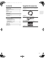
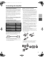
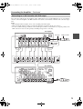
DTA-70.1_En_100108.book
Page 1
Friday, January 8, 2010
2:04 PM
9-Channel Amplifier
DTA-70.1
Instruction Manual
DTA-70.1_En_100108.book
Page 2
Friday, January 8, 2010
2:04 PM
WARNING:
TO REDUCE THE RISK OF FIRE OR ELECTRIC
SHOCK, DO NOT EXPOSE THIS APPARATUS TO
RAIN OR MOISTURE.
CAUTION:
TO REDUCE THE RISK OF ELECTRIC SHOCK,
DO NOT REMOVE COVER (OR BACK). NO
USER-SERVICEABLE PARTS INSIDE. REFER
SERVICING
TO
QUALIFIED
SERVICE
PERSONNEL.
WARNING
AVIS
RISK OF ELECTRIC SHOCK
DO NOT OPEN
RISQUE DE CHOC ELECTRIQUE
NE PAS OUVRIR
The lightning flash with arrowhead symbol, within an
equilateral triangle, is intended to alert the user to the
presence of uninsulated “dangerous voltage” within
the product’s enclosure that may be of sufficient
magnitude to constitute a risk of electric shock to
persons.
The exclamation point within an equilateral triangle is
intended to alert the user to the presence of important
operating and maintenance (servicing) instructions in
the literature accompanying the appliance.
Important Safety Instructions
1.
2.
3.
4.
5.
6.
7.
8.
9.
10.
11.
Read these instructions.
Keep these instructions.
Heed all warnings.
Follow all instructions.
Do not use this apparatus near water.
Clean only with dry cloth.
Do not block any ventilation openings. Install in
accordance with the manufacturer’s instructions.
Do not install near any heat sources such as radiators, heat registers, stoves, or other apparatus
(including amplifiers) that produce heat.
Do not defeat the safety purpose of the polarized or
grounding-type plug. A polarized plug has two
blades with one wider than the other. A grounding
type plug has two blades and a third grounding
prong. The wide blade or the third prong are provided for your safety. If the provided plug does not
fit into your outlet, consult an electrician for
replacement of the obsolete outlet.
Protect the power cord from being walked on or
pinched particularly at plugs, convenience receptacles, and the point where they exit from the apparatus.
Only use attachments/accessories specified by the
manufacturer.
PORTABLE CART WARNING
12. Use only with the cart, stand,
tripod, bracket, or table specified by the manufacturer, or
sold with the apparatus.
When a cart is used, use caution when moving the cart/
S3125A
apparatus combination to
avoid injury from tip-over.
13. Unplug this apparatus during lightning storms or
when unused for long periods of time.
14. Refer all servicing to qualified service personnel.
Servicing is required when the apparatus has been
damaged in any way, such as power-supply cord or
plug is damaged, liquid has been spilled or objects
have fallen into the apparatus, the apparatus has
been exposed to rain or moisture, does not operate
normally, or has been dropped.
2
15. Damage Requiring Service
Unplug the apparatus from the wall outlet and refer
servicing to qualified service personnel under the
following conditions:
A. When the power-supply cord or plug is damaged,
B. If liquid has been spilled, or objects have fallen
into the apparatus,
C. If the apparatus has been exposed to rain or
water,
D. If the apparatus does not operate normally by
following the operating instructions. Adjust
only those controls that are covered by the operating instructions as an improper adjustment of
other controls may result in damage and will
often require extensive work by a qualified technician to restore the apparatus to its normal
operation,
E. If the apparatus has been dropped or damaged in
any way, and
F. When the apparatus exhibits a distinct change in
performance this indicates a need for service.
16. Object and Liquid Entry
Never push objects of any kind into the apparatus
through openings as they may touch dangerous voltage points or short-out parts that could result in a
fire or electric shock.
The apparatus shall not be exposed to dripping or
splashing and no objects filled with liquids, such as
vases shall be placed on the apparatus.
Don’t put candles or other burning objects on top of
this unit.
17. Batteries
Always consider the environmental issues and follow local regulations when disposing of batteries.
18. If you install the apparatus in a built-in installation,
such as a bookcase or rack, ensure that there is adequate ventilation.
Leave 20 cm (8") of free space at the top and sides
and 10 cm (4") at the rear. The rear edge of the shelf
or board above the apparatus shall be set 10 cm (4")
away from the rear panel or wall, creating a fluelike gap for warm air to escape.
DTA-70.1_En_100108.book
Page 3
Friday, January 8, 2010
2:04 PM
Precautions
1. Recording Copyright—Unless it’s for personal use
only, recording copyrighted material is illegal without the permission of the copyright holder.
2. AC Fuse—The AC fuse inside the unit is not userserviceable. If you cannot turn on the unit, contact
the dealer from whom you purchased this unit.
3. Care—Occasionally you should dust the unit all
over with a soft cloth. For stubborn stains, use a soft
cloth dampened with a weak solution of mild detergent and water. Dry the unit immediately afterwards
with a clean cloth. Don’t use abrasive cloths, thinners, alcohol, or other chemical solvents, because
they may damage the finish or remove the panel lettering.
4. Power
WARNING
BEFORE PLUGGING IN THE UNIT FOR THE
FIRST TIME, READ THE FOLLOWING SECTION CAREFULLY.
AC outlet voltages vary from country to country.
Make sure that the voltage in your area meets the
voltage requirements printed on the unit’s rear panel
(e.g., AC 230 V, 50 Hz or AC 120 V, 60 Hz).
The power cord plug is used to disconnect this unit
from the AC power source. Make sure that the plug
is readily operable (easily accessible) at all times.
5.
6.
7.
8.
Pressing the [On/Standby] button to select Standby
mode does not fully shutdown the unit. If you do not
intend to use the unit for an extended period,
remove the power cord from the AC outlet.
Preventing Hearing Loss
Caution
Excessive sound pressure from earphones and headphones can cause hearing loss.
Batteries and Heat Exposure
Warning
Batteries (battery pack or batteries installed) shall
not be exposed to excessive heat as sunshine, fire or
the like.
Never Touch this Unit with Wet Hands—Never
handle this unit or its power cord while your hands
are wet or damp. If water or any other liquid gets
inside this unit, have it checked by the dealer from
whom you purchased this unit.
Handling Notes
• If you need to transport this unit, use the original
packaging to pack it how it was when you originally bought it.
• Do not leave rubber or plastic items on this unit
for a long time, because they may leave marks on
the case.
• This unit’s top and rear panels may get warm
after prolonged use. This is normal.
• If you do not use this unit for a long time, it may
not work properly the next time you turn it on, so
be sure to use it occasionally.
For U.S. models
FCC Information for User
CAUTION:
The user changes or modifications not expressly
approved by the party responsible for compliance could
void the user’s authority to operate the equipment.
NOTE:
This equipment has been tested and found to comply
with the limits for a Class B digital device, pursuant to
Part 15 of the FCC Rules. These limits are designed to
provide reasonable protection against harmful interference in a residential installation.
This equipment generates, uses and can radiate radio frequency energy and, if not installed and used in accordance with the instructions, may cause harmful
interference to radio communications. However, there is
no guarantee that interference will not occur in a particular installation. If this equipment does cause harmful
interference to radio or television reception, which can
be determined by turning the equipment off and on, the
user is encouraged to try to correct the interference by
one or more of the following measures:
• Reorient or relocate the receiving antenna.
• Increase the separation between the equipment and the
amplifier.
• Connect the equipment into an outlet on a circuit different from that to which the receiver is connected.
• Consult the dealer or an experienced radio/TV technician for help.
For Canadian Models
NOTE: THIS CLASS B DIGITAL APPARATUS
COMPLIES WITH CANADIAN ICES-003.
For models having a power cord with a polarized plug:
CAUTION: TO PREVENT ELECTRIC SHOCK,
MATCH WIDE BLADE OF PLUG TO WIDE SLOT,
FULLY INSERT.
Modèle pour les Canadien
REMARQUE: CET APPAREIL NUMÉRIQUE DE
LA CLASSE B EST CONFORME À LA NORME
NMB-003 DU CANADA.
Sur les modèles dont la fiche est polarisée:
ATTENTION: POUR ÉVITER LES CHOCS ÉLECTRIQUES, INTRODUIRE LA LAME LA PLUS
LARGE DE LA FICHE DANS LA BORNE CORRESPONDANTE DE LA PRISE ET POUSSER
JUSQU’AU FOND.
3
DTA-70.1_En_100108.book
Page 4
Friday, January 8, 2010
2:04 PM
Thank you for purchasing an Integra 9-Channel Amplifier. Please read this manual thoroughly before making
connections and plugging in the unit.
Following the instructions in this manual will enable you
to obtain optimum performance and listening enjoyment
from your new 9-Channel Amplifier.
Please retain this manual for future reference.
Features
■ 150 Watts per channel, minimum RMS into
8 ohms, 2 channels driven, from 20 to
20,000 Hz with no more than 0.05 % total
harmonic distortion
■ THX™ Ultra2™ certified*1
■ WRAT–Wide Range Amplifier Technology
(5 Hz-100 kHz bandwidth)
■ Push-Pull amplification design with threestage inverted Darlington circuitry
■ Massive toroidal transformer
■ Customized 22,000 µF large capacitors for
effective power supply
■ Audio-tuned reference capacitors for each
channel
■ Low-impedance, copper bus plates for
perfect ground potential
■ Gold-plated, XLR and machined, solid brass
RCA input terminals
■ Custom-designed large power transistors to
drive high currents
■ High-current, low-impedance circuit board
by using thick copper foil (70 µ)
■ Gold-plated, color-coded, transparent
speaker posts
■ Auto power-down function
■ Multi-zone capability (up to Zone 3)*2
■ Bi-amping capability*2
■ 12V trigger in
■ Aluminum front panel
■ Detachable power cord
*1
THX and Ultra2 are trademarks of THX Ltd. THX may be
registered in some jurisdictions. All rights reserved.
*2 Depends on AV controller
4
DTA-70.1_En_100108.book
Page 5
Friday, January 8, 2010
2:04 PM
Contents
Before using
Important Safety Instructions..................................... 2
Precautions ............................................................... 3
Features .................................................................... 4
Supplied Accessories ................................................ 5
Amplifier Precautions ................................................ 6
Supplied Accessories
Check that the following accessories are supplied with
the DTA-70.1.
Operations
Quick Operation Guide.............................................. 7
Front & Rear Panels.................................................. 8
Front Panel ............................................................ 8
Rear Panel............................................................. 9
Power cord
(Plug type varies from country to country.)
Connections
SP-B/ZONE2
LEFT
SP-B/ZONE2
LEFT
SP-B/ZONE2
RIGHT
SP-B/ZONE2
RIGHT
SP-B/ZONE2
RIGHT
SP-B/ZONE2
RIGHT
CENTER
SP-B/ZONE2
LEFT
SP-B/ZONE2
LEFT
WIDE
RIGHT
WIDE
RIGHT
WIDE
FRONT
RIGHT
FRONT
WIDE
FRONT
RIGHT
FRONT
WIDE
LEFT
FRONT
WIDE
FRONT
LEFT
CENTER
SURROUND BACK
RIGHT
SURROUND BACK
RIGHT
SURROUND BACK
LEFT
SURROUND BACK
LEFT
SURROUND BACK
LEFT
SURROUND BACK
LEFT
SURROUND BACK
RIGHT
SURROUND BACK
RIGHT
WIDE
LEFT
HIGH
RIGHT
HIGH
RIGHT
FRONT
FRONT
FRONT
HIGH
WIDE
HIGH
FRONT
RIGHT
FRONT
RIGHT
FRONT
LEFT
SURROUND
LEFT
SURROUND
RIGHT
SURROUND
RIGHT
SURROUND
LEFT
SURROUND
RIGHT
CENTER
SURROUND
RIGHT
CENTER
HIGH
LEFT
HIGH
LEFT
FRONT
FRONT
HIGH
HIGH
3
FRONT
LEFT
FRONT
LEFT
FRONT
LEFT
FRONT
LEFT
FRONT
RIGHT
FRONT
RIGHT
SURROUND
LEFT
FRONT
LEFT
FRONT
LEFT
SURROUND
LEFT
FRONT
RIGHT
FRONT
RIGHT
Speaker Cable
1
Appendix
Troubleshooting....................................................... 18
Specifications .......................................................... 19
Mono mini-plug cable
(For connecting to the 12V trigger terminals.)
2
Connecting the Amplifier ......................................... 11
Connecting Your Speakers.................................. 11
Connecting to an AV Controller
with XLR output................................................. 13
Connecting to an AV Controller
with RCA output ................................................ 14
Bi-amping the Front Speakers............................. 15
Multiroom Connections........................................ 16
Speaker cable labels
5
DTA-70.1_En_100108.book
Page 6
Friday, January 8, 2010
2:04 PM
Amplifier Precautions
Before using the DTA-70.1 power amplifier, be sure to
read the page above entitled Important Safety Instructions and this page of Amplifier Precautions.
Ventilation
While using the DTA-70.1, the internal temperature will
fairly rise. Excessive temperature rise may affect the
amplifier performance. To prevent damage from occurring due to high internal temperatures, it is vital to have
proper ventilation and passage of air to carry out the heat
and keep the internal temperature within acceptable
ranges.
Caution
• Do not place the DTA-70.1 inside cabinets or closets
where there is poor passage of air and ventilation.
• Do not place the DTA-70.1 near external heat sources
such as heaters or hot air ducts.
• Do not place other components or object on top of or
under the DTA-70.1.
• The cover of the DTA-70.1 contains ventilation holes
to allow the passage of air. Do not cover or block these
holes in any way.
If you are planning to place it within a cabinet, either
open holes in the rear panel of the cabinet to improve
ventilation or use a fan to force air circulation.
As a general rule, if during idling the cover is too hot to
touch, then ventilation needs to be improved.
Installation location and space
Make sure that the floor or cabinet or rack where it will
be located is strong enough to support its weight.
You will also need to leave enough space behind the
DTA-70.1 to allow room for the power cord and other
cables for connecting system components. A minimum
of four inches is required behind the DTA-70.1 to allow
room for the cables and cords without excessively bending them.
Do not place the DTA-70.1 near TV or radio. This may
cause noise or instable video on radio or TV respectively.
Power cord
Do not use a power cord other than the one supplied with
the DTA-70.1. The power cord supplied is designed for
use with the DTA-70.1 and should not be used with any
other device.
Be sure to only use wall sockets that properly fit the plug
of the power cord. If the socket does not match the plug
of the power cord, you will need to prepare an adapter.
Always use an adapter that is properly certified for this
application.
6
Speakers
Connected speakers should have an impedance of
4 ohms or greater.
If speakers with an impedance of less than 4 ohms are
connected, it may damage the DTA-70.1.
Care
From time to time you should wipe the front and rear
panels and the cabinet with a soft cloth. For heavier dirt,
dampen a soft cloth in a weak solution of mild detergent
and water, wring it out dry, and wipe off the dirt. Following this, dry immediately with a clean cloth. Do not use
rough material, thinners, alcohol or other Chemical solvents or cloths since these could damage the finish or
remove the panel lettering.
Whenever performing maintenance on the DTA-70.1,
any of its supplied accessories, or any device connected
to it, do not use solvents or cleaners of any kind that are
inflammable or combustible.
When you clean the input/output terminals on the rear
panel, do not use contact restorer. Doing so may cause
resin deterioration.
Other
Below is a list of actions that you should never perform.
• Do not use the DTA-70.1 as a broadcast system or
musical instrument amplifier.
• Never use a generator, DC/AC converter, AC/AC converter, or transformer to supply power for the
DTA-70.1.
• Never perform a “thumb test” (checking whether current is reaching the lead wire on the hot end of the
input by touching it with your fingers) on the ends of
the input jacks or input cables.
Doing so may damage the speakers.
• Do not short across the output terminals or across the
output terminals and rear panel.
• Never remove the cover of the DTA-70.1.
• Do not install the DTA-70.1 in a location within the
reach of small children.
Lightning storms
During lightning storm, never touch the power cord, plug
or cover of the DTA-70.1, and any devices connected to
the DTA-70.1.
Power
WARNING:
BEFORE PLUGGING IN THE UNIT FOR THE FIRST
TIME, READ THE FOLLOWING SECTION CAREFULLY.
AC outlet voltages vary from country to country. Make
sure that the voltage in your area meets the voltage
requirements printed on the unit’s rear panel (e.g., AC
220-240 V, 50/60 Hz or AC 120 V, 60 Hz).
DTA-70.1_En_100108.book
Page 7
Friday, January 8, 2010
2:04 PM
Quick Operation Guide
Here is a quick guide for those who want to listen to
music or view their favorite movies as soon as possible.
Connections and operations are explained briefly here
for the purpose of just getting you started.
For those of you who want to operate the DTA-70.1 (the
amplifier) right away, follow the guide below. However,
this instruction manual contains a great deal of other
information that you should know for the proper operation of the amplifier and for a more pleasurable experience with the amplifier. Be sure to read the rest of this
manual as well after reading this quick guide.
The procedures given below assume that the other system components are already connected and configured.
(For example, that the source components are already
connected to the control amplifier.)
1. Lower the volume at the control amplifier.
Lower the volume of the control amplifier to the
minimum so that when the amplifier is turned on,
you do not hear loud unwanted sounds.
2. Connect the speakers to the amplifier.
Connect the speakers to the amplifier using the
proper speaker cables. Be sure to match the channels
and the positive (+) and negative (–) polarities
between the speakers and the amplifier. If the connections are mistaken, the correct orientation will
not be obtained.
3. Select balanced input (XLR) or unbalanced input
(RCA) with the INPUT SELECT switch.
The amplifier possesses a balanced input (XLR) and
unbalanced input (RCA) for each channel and the
switch for the two is located between the two input
terminals. Select the proper input type depending on
the functionality of the connected cables and the
control amplifier.
Note:
Do not change the INPUT SELECT switch setting when
the amplifier is turned on.
4. Connect the control amplifier to the amplifier.
After selecting the correct input type in step 3 above,
connect the output from the control amplifier to the
corresponding input terminal on the amplifier.
Note:
Do not connect anything to the other input jack.
5. Connect the supplied power cord to the amplifier
and to the wall power outlet.
Be sure to properly plug the power cord all the way
in.
6. Press the Power switch.
The Standby indicator lights red.
7. Press the On/Standby button.
The On indicator lights blue.
When you connect other device to the 12V TRIGGER IN terminal using the supplied cable, the power
on or off status of the amplifier synchronizes to the
action of turning on or off the connected device.
While the Standby indicator lights red, the amplifier
is in standby state waiting for 12V trigger signal.
8. Slowly increase the control amplifier volume.
Note:
After the amplifier is turned on, it takes approximately
10 seconds before the output sounds. During this time,
do not turn up the volume.
Now all that remains is to control the control amplifier
and the other connected system components and enjoy
your music or movies.
7
DTA-70.1_En_100108.book
Page 8
Friday, January 8, 2010
2:04 PM
Front & Rear Panels
Front Panel
ab c
8
d
a Power switch
This is the main power switch. When set to OFF,
the amplifier is completely shutdown. It must be set
to On to set the amplifier to On or Standby.
c Standby indicator
The amplifier is in standby state and waits for
instruction signal from the 12V TRIGGER IN terminal.
b On/Standby button
This button is used to set the amplifier to On or
Standby.
Note:
If you wish to turn on the amplifier again after it is turned
off, wait for several seconds.
d On indicator
The main power of the amplifier is turned on and
you can play and enjoy an input source.
Notes:
• If the Power switch is pressed and both of the On and
Standby indicators do not light, check that the power
cord is properly connected. If the indictors still do not
light, turn off the amplifier, disconnect the power cord
from wall outlet, and contact the dealer from whom
you purchased this unit.
• If the Standby indicator flashes red, the protection circuitry of the amplifier has activated. The protection
circuitry activates if a problem such as a speaker cable
shorting or excessive temperature occurs. Turn off the
amplifier, remove the cause of the problem, and then
turn it back on. If the problem is still not solved, turn
off the amplifier, disconnect the power cord from wall
outlet, and contact the dealer from whom you purchased this unit.
DTA-70.1_En_100108.book
Page 9
Friday, January 8, 2010
2:04 PM
Front & Rear Panels—Continued
Rear Panel
This unit comprises 9 independent power amplifiers, each being capable of reproducing the same quality sound through
its channel. Note that you should connect an input source and a speaker to each channel in use.
Caution
• Do not connect the power cord until you have finished all other connections.
• Read the instructions that came with the other components you are connecting.
• Do not make connections to input or output jacks while the amplifier is turned on (Power
On).
• Turn the volume of the control amplifier down before turning on the amplifier.
e f
g
h
a
b
c
d
a Balanced Input (XLR terminal)
Connect AV controllers or control amplifiers with
balanced outputs for high-quality sound.
3
1
1. GND
Plugging the XLR cable
Match the pins and insert the terminal until you hear a
“click.” Make sure that the terminal is locked by lightly
pulling the connection cable.
2
3. COLD
2. HOT
Connector ground terminal: Chassis grounded
The pin assignments for this terminal are given
above. This pin assignment conforms to the standard adopted by the Audio Engineering Society.
Refer to the instruction manual supplied with the
control amplifier and verify that its output terminal
is compatible with the pin assignments for this terminal. The output terminal of Integra DTC-80.1 is
compatible with the pin assignments for the terminal of the amplifier.
The amplifier uses the European type XLR terminal. Phase is reversed when an XLR cable is connected to the control amplifier that uses the USA
type XLR terminal. In this case, swap pin 2 and pin
3 to set the polarity to the European type before
connecting.
Unpugging the XLR cable
Pull out the connection cable while holding down the
lever.
Push
Notes:
• When using this balanced connection for a specific
channel between the control amplifier and the amplifier, set the INPUT SELECT switch to the upper side
(the balanced input side) to select balanced input.
Next, use commercial XLR balanced cable and connect the balanced output from the control amplifier to
the corresponding balanced input on the amplifier.
• Do not connect anything to the RCA-type audio input
jack.
9
DTA-70.1_En_100108.book
Page 10
Friday, January 8, 2010
2:04 PM
Front & Rear Panels—Continued
b INPUT SELECT switch
This switch is located between the balanced input
and single-ended RCA input for each channel. Use
this switch to select the input type for its channel.
When setting the switch to the upper side, the balanced input is selected.
When setting the switch to the lower side, the RCA
audio input is selected.
Notes:
• Do not change the INPUT SELECT switch setting
when the amplifier is turned on.
• Make sure that connections have been made only to
the inputs selected with the INPUT SELECT switches
and nothing is connected to the other ones.
c Unbalanced Input (single end RCA input)
Connect AV controllers or control amplifiers with
single-ended outputs.
RCA type
Notes:
• When using this single-ended connection for a specific channel, set the INPUT SELECT switch to the
lower side (the RCA audio input side), use commercial RCA audio pin cable and connect the singleended outputs.
• Do not connect anything to the balanced input jack.
d OUTPUT (Speaker output and binding post)
These terminal posts are for connecting the front
L/R, center, surround L/R, surround back L/R, and
front high/wide L/R speakers.
The FRONT L/R and SURR BACK L/R terminal
posts can be used with front speakers and surround
back speakers respectively, or used to bi-amp the
front speakers. See “Bi-amping the Front Speakers”
on page 15.
e SPEAKER IMPEDANCE switch
Use this switch to select the speaker impedance.
4Ω: Select if the impedance of any speaker is
4 ohms or more but less than 6.
6Ω: Select if the impedances of all speakers are
between 6 and 16 ohms.
f AUTO POWER DOWN switch
You can use the auto power-down function. If the
amplifier receives no signal for 3 hours, it will automatically enter standby mode. Once the auto powerdown function has been activated, the amplifier will
not automatically turn on even if it receives the signal. To turn on the amplifier, press the On/Standby
button manually. You can also disable the function
by setting this switch to OFF side.
Default setting: ON (Australian models), OFF
(North American models)
10
Notes:
• Regardless of the position of this switch, this function
will not work when the amplifier has been turned on
by the 12V trigger.
• Before entering standby mode by the auto powerdown function, the amplifier notifies you by flashing
the On indicator for 10 seconds.
• Depending on some sources, the auto power-down
function may activate during playback.
g 12V TRIGGER IN
Connects to the 12V trigger output terminal on the
other component to control the amplifier. This
enables the amplifier to turn on or go into standby
state based on the power on/standby status of the
connected component.
Use the supplied or commercially available 1/8-inch
mono cable to connect to the 12V trigger output terminal on the other device.
The tip polarity of the connectors are as shown
below.
5 to 12 volts, positive
tip polarity
h AC INLET
Plug the supplied power cord into this AC INLET
and then into the power outlet on the wall.
Power cord
(supplied)
To an AC wall
outlet
• Do not plug the amplifier into the AC outlet other than
an AC wall socket.
• Do not use a power cord other than the one supplied
with the amplifier. The power cord supplied is
designed for use with the amplifier and should not be
used with any other device.
• Never have the power cord disconnected from the
amplifier while the other end is plugged into the wall
outlet. Doing so may cause an electric shock. Always
connect by plugging into the wall outlet last and disconnect by unplugging from the wall outlet first.
• Before you plug in the amplifier, confirm that all connections have been made properly.
• Turning on the power may cause a momentary power
surge, which might interfere with other electrical
equipment on the same circuit, such as computers. If
this happens, use a wall outlet on a different circuit.
DTA-70.1_En_100108.book
Page 11
Friday, January 8, 2010
2:04 PM
Connecting the Amplifier
Connecting Your Speakers
Before connecting the speakers, place them correctly by
consulting the instruction manuals that came with them.
For surround playback, the configuration and placement
of your speakers are very important.
Please note that connecting speakers with a low power
input rating does not produce large sound volumes. For
those speakers, large sound volumes causing excessive
input level may damage the speakers.
Note:
Once you’ve completed speaker connections, you must
turn on the AV controller or control amplifier and configure the output channels.
Attaching the Speaker Labels
The amplifier’s positive (+) speaker terminals are all red
(the negative (–) speaker terminals are all black).
Speaker
Color
Front left
White
Front right
Red
Center
Green
Surround left
Blue
Surround right
Gray
Surround back left
Brown
Surround back right
Tan
Front high/wide left
White
Front high/wide right
Red
The supplied speaker cable labels are also color-coded
and you should attach them to the positive (+) side of
each speaker cable in accordance with the above table.
Then all you need to do is to match the color of each
label to the corresponding speaker terminal.
Speaker Connection Precautions
Read the following before connecting your speakers:
• You can connect speakers with an impedance of
between 4 and 16 ohms. If the impedance of any of the
connected speakers is 4 ohms or more, but less than 6
ohms, be sure to set the minimum speaker impedance
to “4ohms” (see page 10). If you use speakers with a
lower impedance, and use the amplifier at high volume levels for a long period of time, the built-in protection circuit may be activated.
• Disconnect the power cord from the wall outlet before
making any connections.
• Read the instructions supplied with your speakers.
• Pay close attention to speaker wiring polarity. In other
words, connect positive (+) terminals only to positive
(+) terminals, and negative (–) terminals only to negative (–) terminals. If you get them the wrong way
around, the sound will be out of phase and will sound
unnatural.
• Unnecessarily long, or very thin speaker cables may
affect the sound quality and should be avoided.
• If you use 4 or 5 speakers, connect each of the two
surround speakers to the SURR L/R terminals. Do not
connect them to the SURR BACK L/R or FRONT
HIGH/WIDE L/R terminals.
• Be careful not to short the positive and negative wires.
Doing so may damage the amplifier.
• Make sure the metal core of the wire does not have
contact with the amplifier’s rear panel. Doing so may
damage the amplifier.
(North American models)
• If you are using banana plugs, tighten the speaker terminal before inserting the banana plug.
• Do not insert the speaker code directly into the center
hole of the speaker terminal.
• Don’t connect more than one cable to each speaker
terminal. Doing so may damage the amplifier.
• Don’t connect one speaker to several terminals.
11
DTA-70.1_En_100108.book
Page 12
Friday, January 8, 2010
2:04 PM
Connecting the Amplifier—Continued
Connecting the Speaker Cables
1
2
Strip about 1/2" to 5/8"
(12 to 15 mm) of insulation from the ends of
the speaker cables,
and twist the bare
wires tightly, as
shown.
1/2" to 5/8"
(12 to 15 mm)
3
Fully insert the bare wires.
4
Screw the terminal tight.
Unscrew the terminal.
The following illustration shows which speaker should be connected to each pair of terminals. If you’re using only one
surround back speaker, connect it to the SURR BACK L terminal.
Note:
If you use front high or front wide speakers, you must turn on the AV controller and select the speakers to be used.
For more details, see the instruction manual of the connected component.
Select 4Ω or 6Ω.
Surround
right
speaker
Front high/wide
right speaker
12
Surround
back right
speaker
Front right
speaker
Center
speaker
Front left
speaker
Surround
left
speaker
Surround
back left
speaker
Front high/wide
left speaker
DTA-70.1_En_100108.book
Page 13
Friday, January 8, 2010
2:04 PM
Connecting the Amplifier—Continued
Connecting to an AV Controller with XLR output
Since many users will purchase the amplifier together with the Integra AV controller DHC-80.1, here is an explanation
of how to connect the amplifier to the DHC-80.1. For more details, see the instruction manual of the connected component.
Notes:
• When using the balanced inputs, do not connect anything to the RCA inputs.
• Make sure that the balanced cable is not split. The split balanced cable may be the cause of noise.
• If a device with the USA type terminal is connected, the phase will be reversed. In this case, swap the polarity of the
XLR connector in order to set the polarity to the European type before connecting.
The amplifier
XLR type
Balanced cable
From the AV controller
AV controller
From the amplifier
13
DTA-70.1_En_100108.book
Page 14
Friday, January 8, 2010
2:04 PM
Connecting the Amplifier—Continued
Connecting to an AV Controller with RCA output
Since many users will purchase the amplifier together with the Integra AV controller DHC-80.1, here is an explanation
of how to connect the amplifier to the DHC-80.1. For more details, see the instruction manual of the connected component.
Notes:
• When using the RCA inputs, do not connect anything to the balanced inputs.
• Make sure that the pin cable is not split. The split pin cable may be the cause of noise.
• Push plugs in all the way to make good connections (loose connections can cause noise or malfunctions).
• To prevent interference, keep audio and video cables away from power cords and speaker cables.
The amplifier
Right!
Wrong!
AV controller
14
DTA-70.1_En_100108.book
Page 15
Friday, January 8, 2010
2:04 PM
Connecting the Amplifier—Continued
Bi-amping the Front Speakers
The FRONT L/R and SURR BACK L/R outputs can be used with front speakers and surround back speakers respectively, or bi-amped to provide separate tweeter and woofer feeds for a pair of front speakers that support bi-amping,
providing improved bass and treble performance.
Notes:
• Please make sure that your AV controller supports bi-amping.
• When bi-amping is used, the amplifier is able to feed up to 7-channel speakers in the main room.
• When bi-amping is used, surround back speakers cannot be used.
• For bi-amping, the FRONT L/R outputs feed the front speakers’ woofer terminals. And the SURR BACK L/R outputs
feed the front speakers’ tweeter terminals.
• Once you’ve completed the bi-amping connections shown below, you must turn on the AV controller and configure
it to enable bi-amping. For more details, see the instruction manual of the connected component.
• You can also use unbalanced (RCA) connections for bi-amping.
Important:
• When making the bi-amping connections, be sure to remove the jumper bars that link the speakers’ tweeter
(high) and woofer (low) terminals.
• Bi-amping can only be used with speakers that support bi-amping. Refer to your speaker manual.
AV controller
The amplifier
Front high/wide
right speaker
Surround right
speaker
Center speaker
Surround left
speaker
Front high/wide
left speaker
Tweeter (high)
Woofer (low)
Front right speaker
Front left speaker
15
DTA-70.1_En_100108.book
Page 16
Friday, January 8, 2010
2:04 PM
Connecting the Amplifier—Continued
Multiroom Connections
You can use three speaker systems with this amplifier—a surround-sound speaker system in your main listening
room, Zone 2: a stereo speaker system in a second room, Zone 3: a stereo speaker system in a third room. The following
examples are based on using the amplifier with the AV controller, DHC-80.1. For more details, see the instruction
manual of the connected component.
Notes:
• Please make sure that your AV controller has the multi-zone capability.
• Once you’ve completed multi-zone connections shown below, you must turn on the AV controller and configure it to
enable the multi-zone capability.
• If your AV controller has balanced outputs for multiroom versatility, you can also use the balanced inputs on the
amplifier.
■ Connection 1
Main room: You can enjoy up to 5-channel surround-sound playback.
Zone 2: You can enjoy 2-channel stereo playback and video playback.
Zone 3: You can enjoy 2-channel stereo playback.
Zone 2
Zone 3
Make either
connection.
AV controller
Front right
speaker
Front left
speaker
Front right
speaker
The amplifier
See page 13 or 14 for the connection.
Main room
Surround right
speaker
16
Front right
speaker
Center speaker
Front left
speaker
Surround left
speaker
Front left
speaker
DTA-70.1_En_100108.book
Page 17
Friday, January 8, 2010
2:04 PM
Connecting the Amplifier—Continued
■ Connection 2
Main room: You can enjoy up to 7-channel surround-sound playback.
Zone 2: You can enjoy 2-channel stereo playback and video playback.
Zone 2
Make either connection.
AV controller
Front right
speaker
Front left
speaker
The amplifier
See page 13 or 14 for the connection.
Main room
Surround back Surround right
right speaker
speaker
Front right
speaker
Center speaker
Front left
speaker
Surround left Surround back
speaker
left speaker
17
DTA-70.1_En_100108.book
Page 18
Friday, January 8, 2010
2:04 PM
Troubleshooting
If the DTA-70.1 fails to function normally, first check the
following points before contacting the dealer from
whom you purchased this unit. If the problem is not
solved after going through the following list, unplug the
power cord and contact the dealer from whom you purchased this unit.
No power.
• Power cord is not correctly plugged into AC outlet/
Inlet.
→ Plug the power cord into the AC outlet/Inlet properly.
• Power switch is not set to On position.
→ Set the Power switch to On.
Power turns on but no sound.
• Incomplete connections.
→ Check speaker cable connections.
→ Insert all plugs firmly into jacks.
• No input signal from control amplifier.
→ Check for input signal from control amplifier.
• Incorrect INPUT SELECT switch setting.
→ Set INPUT SELECT switch to correct setting.
The Standby indicator flashes red.
• The protection circuitry has been activated.
→ Remove the power cord from the wall outlet
immediately. Set the Power switch to Off, disconnect
all speaker cables and input sources, and then leave
the amplifier with its power cord disconnected for 1
hour. After that, reconnect the power cord, set the
Power switch to On. If the amplifier stays on, disconnect the power cord, and reconnect your speakers
and input sources. If the amplifier turns off, disconnect the power cord, and contact the dealer from
whom you purchased this unit.
The 12V trigger of the DTA-70.1 does not react
to that of the DHC-80.1.
• Connection between the 12V trigger terminals is
incomplete.
→ Connect the cables to the terminals firmly.
Humming or other noise is heard.
• Input cable connection is incomplete.
→ Insert the input cable to pin jack or connector
completely.
• Noise from power cord or power transformer affects
the input cable.
→ Keep power cord or power transformer away from
the input cable.
• Power cord or speaker cables are bundled together
with pin cords.
→ This may cause humming or noise. Do not bundle
power cord or speaker cables with pin cables
together.
18
• Connection to the input terminals is not complete or
not appropriate.
→ For each channel’s input terminals, connect cables
or cords to either balanced input terminal or audio
input terminal only and switch the INPUT SELECT
switch accordingly.
Avoid connecting the cables or cords to the input terminals that will not be used.
DTA-70.1_En_100108.book
Page 19
Friday, January 8, 2010
2:04 PM
Specifications
Amplifier section
Rated Output Power
All channels:
North American:
150 watts minimum continuous
power per channel, 8 ohm loads,
2 channels driven from 20 Hz to
20 kHz, with a maximum total
harmonic distortion of 0.05% (FTC)
175 watts minimum continuous
power per channel, 8 ohm loads,
2 channels driven from 20 Hz to
20 kHz with a maximum total
harmonic distortion of 0.7% (FTC)
185 watts minimum continuous
power per channel, 6 ohm loads,
2 channels driven at 1 kHz, with a
maximum total harmonic distortion
of 0.1% (FTC)
Australian:
9 ch × 220 W at 6 ohms, 1 kHz, 1 ch
driven (IEC)
Maximum Effective Output Power
Australian:
9 ch × 280 W at 6 ohms, 1 kHz, 1 ch
driven (JEITA)
Dynamic Power
400 W (3 Ω, Front)
300 W (4 Ω, Front)
180 W (8 Ω, Front)
THD (Total Harmonic Distortion)
0.05 % (Power Rated)
Damping Factor
60 (Front, 1 kHz, 8 Ω)
Input Sensitivity and Impedance
1 V, 47 kΩ (Unbalanced)
2 V, 22 kΩ (Balanced)
Frequency Response
5 Hz - 100 kHz/+1 dB - 3 dB
Signal to Noise Ratio
110 dB (Unbalanced, IHF-A)
Speaker Impedance
4 Ω - 16 Ω
General
Power Supply
North American:
AC 120 V, 60 Hz
Australian:
AC 220 - 240 V, 50/60 Hz
Power Consumption
North American: 11.7 A
Australian: 1050 W
Dimensions (W × H × D)
435 × 198.5 × 445 mm
Weight
17-1/8" × 7-13/16" × 17-1/2"
23 kg (50.7 lbs.)
■ Audio Inputs
Balance Inputs
Unbalance Inputs
9
9
■ Speaker Outputs
FL, FR, C, SL, SR, SBL, SBR, LH, RH
■ Control Terminal
12 V Trigger In
1
Specifications and features are subject to change
without notice.
19
DTA-70.1_En_100108.book
Page 20
Friday, January 8, 2010
2:04 PM
Integra Division of
ONKYO U.S.A. CORPORATION
18 park Way, Upper Saddle River, N.J. 07458, U.S.A.
Tel: 800-225-1946, 201-818-9200 Fax: 201-785-2650 http://www.integrahometheater.com
Integra Division of
ONKYO CORPORATION
Sales & Product Planning Div.: 2-1, Nisshin-cho, Neyagawa-shi, OSAKA 572-8540, JAPAN
Tel: 072-831-8023 Fax: 072-831-8163
En
Y1001-1
SN 29400191
(C) Copyright 2010 ONKYO CORPORATION Japan. All rights reserved.
* 2 9 4 0 0 1 9 1 *