1
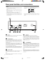
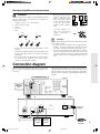
Contents
2 Channel Amplifier
Before using
Important Safeguards ....................................... 2
Features ............................................................. 3
ADM-2.1
Supplied accessory ........................................... 3
Precautions ........................................................ 3
Instruction Manual
Facilities and connections
Rear panel facilities and connections ............... 4
Connection diagram .......................................... 5
Front panel facilities and connections .............. 6
Operations ......................................................... 7
Thank you for purchasing the Integra 2 Channel
Amplifier.
Please read this manual thoroughly before making
connections and plugging in the unit.
Following the instructions in this manual will enable
you to obtain optimum performance and listening
enjoyment from your new 2 Channel Amplifier. Please
retain this manual for future reference.
#US_ADM-2.1_01.p65
1
Appendix
Troubleshooting guide ...................................... 7
Specifications ................................... Back cover
8/25/00, 6:22 PM
WARNING:
TO REDUCE THE RISK OF FIRE OR ELECTRIC SHOCK,
DO NOT EXPOSE THIS APPLIANCE TO RAIN OR
MOISTURE.
CAUTION:
TO REDUCE THE RISK OF ELECTRIC SHOCK, DO NOT
REMOVE COVER (OR BACK). NO USER-SERVICEABLE
PARTS INSIDE. REFER SERVICING TO QUALIFIED
SERVICE PERSONNEL.
WARNING
AVIS
RISK OF ELECTRIC SHOCK
DO NOT OPEN
RISQUE DE CHOC ELECTRIQUE
NE PAS OUVRIR
The lightning flash with arrowhead symbol, within an equilateral
triangle, is intended to alert the user to the presence of uninsulated
“dangerous voltage” within the product’s enclosure that may be of
sufficient magnitude to constitute a risk of electric shock to persons.
The exclamation point within an equilateral triangle is intended to
alert the user to the presence of important operating and maintenance
(servicing) instructions in the literature accompanying the appliance.
Important Safeguards
1. Read Instructions – All the safety and operating instructions
should be read before the appliance is operated.
2. Retain Instructions – The safety and operating instructions
should be retained for future reference.
3. Heed Warnings – All warnings on the appliance and in the
operating instructions should be adhered to.
4. Follow Instructions – All operating and use instructions
should be followed.
5. Cleaning – Unplug the appliance from the wall outlet before
cleaning. The appliance should be cleaned only as recommended by the manufacturer.
6. Attachments– Do not use attachments not recommended by
the appliance manufacturer as they may cause hazards.
7. Water and Moisture –Do not use the appliance near water –for
example, near a bath tub, wash bowl, kitchen sink, or laundry
tub; in a wet basement; or near a swimming pool; and the like.
8. Accessories – Do not place the appliance on an unstable cart,
stand, tripod, bracket, or table. The appliance may fall, causing
serious injury to a child or adult, and serious damage to the
appliance. Use only with a cart, stand, tripod, bracket, or table
recommended by the manufacturer, or sold with the appliance.
Any mounting of the appliance
should follow the manufacturer’s PORTABLE CART WARNING
instructions, and should use a
mounting accessory recommended
by the manufacturer.
9. An appliance and cart combination
should be moved with care. Quick
stops, excessive force, and uneven
surfaces may cause the appliance S3125A
and cart combination to overturn.
10. Ventilation – Slots and openings in the cabinet are provided
for ventilation and to ensure reliable operation of the appliance
and to protect it from overheating, and these openings must not
be blocked or covered. The openings should never be blocked
by placing the appliance on a bed, sofa, rug, or other similar
surface. The appliance should not be placed in a built-in installation such as a bookcase or rack unless proper ventilation is
provided. There should be free space of at least 20 cm (8 in.)
and an opening behind the appliance.
11. Power Sources – The appliance should be operated only from
the type of power source indicated on the marking label. If you
are not sure of the type of power supply to your home, consult
your appliance dealer or local power company.
12. Grounding or Polarization – The appliance may be equipped
with a polarized alternating current line plug (a plug having
one blade wider than the other). This plug will fit into the
power outlet only one way. This is a safety feature. If you are
unable to insert the plug fully into the outlet, try reversing the
plug. If the plug should still fail to fit, contact your electrician
to replace your obsolete outlet. Do not defeat the safety purpose of the polarized plug.
13. Power-Cord Protection – Power-supply cords should be
routed so that they are not likely to be walked on or pinched by
items placed upon or against them, paying particular attention
to cords at plugs, convenience receptacles, and the point where
they exit from the appliance.
14. Lightning – For added protection for the appliance during a
lightning storm, or when it is left unattended and unused for
long periods of time, unplug it from the wall outlet and disconnect the antenna or cable system. This will prevent damage to
the appliance due to lightning and power-line surges.
15. Overloading – Do not overload wall outlets, extension cords,
or integral convenience receptacles as this can result in a risk
of fire or electric shock.
16. Object and Liquid Entry – Never push objects of any kind
into the appliance through openings as they may touch dangerous voltage points or short-out parts that could result in a fire
or electric shock. Never spill liquid of any kind on the appliance.
17. Servicing – Do not attempt to service the appliance yourself as
opening or removing covers may expose you to dangerous
voltage or other hazards. Refer all servicing to qualified service personnel.
18. Damage Requiring Service – Unplug the appliance from the
wall outlet and refer servicing to qualified service personnel
under the following conditions:
A. When the power-supply cord or plug is damaged,
B. If liquid has been spilled, or objects have fallen into the
appliance,
C. If the appliance has been exposed to rain or water,
D. If the appliance does not operate normally by following
the operating instructions. Adjust only those controls that
are covered by the operating instructions as an improper
adjustment of other controls may result in damage and will
often require extensive work by a qualified technician to
restore the appliance to its normal operation,
E. If the appliance has been dropped or damaged in any way,
and
F. When the appliance exhibits a distinct change in performance – this indicates a need for service.
19. Replacement Parts–When replacement parts are required, be
sure the service technician has used replacement parts specified by the manufacturer or have the same characteristics as
the original part. Unauthorized substitutions may result in fire,
electric shock, or other hazards.
20. Safety Check – Upon completion of any service or repairs to the
appliance, ask the service technician to perform safety checks to
determine that the appliance is in proper operation condition.
21. Wall or Ceiling Mounting – The appliance should be mounted
to a wall or ceiling only as recommended by the manufacturer.
22. Heat – The appliance should be situated away from heat
sources such as radiators, heat registers, stoves, or other appliances (including amplifiers) that produce heat.
2
#US_ADM-2.1_02-03.p65
2
8/25/00, 6:22 PM
Features
Precautions
WIDE RANGE AMPLIFIER TECHNOLOGY (WRAT)
WRAT virtually eliminates the adverse effects of counterelectromotive force by:
1) applying an uncommonly low amount of NFB (negative feedback),
2) using carefully selected, high-tolerance, wide range parts in all
critical sections, and
3) incorporating innovative circuit topology based upon decades
of high-end amplifier design experience — the final result is flat
response beyond 100 kHz.
1. Warranty Claim
You can find the serial number on the rear panel of this unit. In
case of warranty claim, please report this number.
AUTO POWER ON/OFF FUNCTION
You can turn on and off the ADM-2.1 via a signal input to the
AUDIO IN jacks or 12V TRIGGER IN jack.
AUDIO IN/OUT LINK FUNCTION
The signal inputs from the AUDIO IN jacks are output from the
AUDIO OUT jacks. When used as a 2 channel amplifier in a multi
room configuration, you can connect several ADM-2.1s to enjoy
the same source in several rooms.
2. Recording Copyright
Recording of copyrighted material for other than personal use is
illegal without permission of the copyright holder.
3. AC Fuse
The fuse is located inside the chassis and is not user-serviceable. If
the power does not come on, contact your Integra/Onkyo authorized service station.
4. Care
From time to time you should wipe the front and rear panels and
the cabinet with a soft cloth. For heavier dirt, dampen a soft cloth
in a weak solution of mild detergent and water, wring it out dry,
and wipe off the dirt. Following this, dry immediately with a clean
cloth. Do not use rough material, thinner, alcohol or other chemical solvents or cloths since these could damage the finish or remove the panel lettering.
5. Power
WARNING
BEFORE PLUGGING IN THE UNIT FOR THE FIRST TIME,
READ THE FOLLOWING SECTION CAREFULLY.
The voltage of the available power supply differs according to
country or region. Be sure that the power supply voltage of the
area where this unit will be used meets the required voltage (e.g.,
AC 120 V, 60 Hz) written on the rear panel.
For Canadian models
For models having a power cord with a polarized plug:
CAUTION: TO PREVENT ELECTRIC SHOCK, MATCH
WIDE BLADE OF PLUG TO WIDE SLOT, FULLY INSERT.
Modele pour les Canadien
Sur les modèles dont la fiche est polarisée:
ATTENTION: POUR ÉVITER LES CHOCS ÉLECTRIQUES,
INTRODUIRE LA LAME LA PLUS LARGE DE LA FICHE
DANS LA BORNE CORRESPONDANTE DE LA PRISE ET
POUSSER JUSQU’AU FOND.
Supplied accessory
Check that the following accessory is supplied with the ADM-2.1.
Power cord × 1
3
#US_ADM-2.1_02-03.p65
3
8/25/00, 6:22 PM
Rear panel facilities and connections
Caution:
• Be sure to always refer to the instructions that came with the
component that you are connecting.
• Do not plug in the power cord until all connections have been
made.
• Do not make connections to input or output jacks while the
ADM-2.1 is turned on.
• Always turn the volume of the control amplifier or
preamplifier down before turning on the ADM-2.1.
• For input and output jacks, red connectors (marked R) are used
for the right channel and white connectors (marked L) are used
for the left channel.
• Insert all plugs and connectors securely. Improper connections
can result in noise, poor performance, or damage to the
equipment.
Improper connection
Inserted completely
• Do not bind audio connection cables with power cords and
speaker cables. Doing so may adversely affect the sound
quality.
AC INLET
SPEAKERS
GND
2 CHANNEL AMPLIFIER
MODEL NO. ADM-2.1
INPUT
LEVEL
AUDIO
OUT
IN
L
L
R
R
TRIGGER
AUDIO
12 V
TRIGGER
12 V
OFF TRIGGER
IN
MIN
L
L
R
R
MAX
GND
TRIGGER
Use this GND terminal for connecting the ground (or earth) wire
of other component if humming noise is heard.
AUDIO IN/OUT
These are the analog audio inputs and outputs. Use an RCA-type
audio connection cable to connect the output jacks of the device to
the AUDIO IN jacks on the ADM-2.1. When connecting a control
amplifier or preamplifier, connect the PRE OUT jacks to the
AUDIO IN jacks.
If you connect the AUDIO OUT jacks of the ADM-2.1 to the
AUDIO IN jacks of another ADM-2.1, the signal input at the
AUDIO IN jacks of the ADM-2.1 is also output from the AUDIO
OUT jacks (Audio In/Out Link Function).
If you set the TRIGGER switch to AUDIO, the power of the
connected ADM-2.1 turns on automatically when an audio signal
is supplied to the AUDIO IN jacks (Auto Power On/Off Function).
INPUT LEVEL
Turn this INPUT LEVEL control to adjust the input level of the
signal from the AUDIO IN jacks. Normally, set to MAX.
4
Set this TRIGGER switch before turning on the ADM-2.1.
To turn on the ADM-2.1 with the signal input from the 12V
TRIGGER IN jack, set the TRIGGER switch to 12V TRIGGER.
To turn on the ADM-2.1 with the signal input from the AUDIO IN
jack, set the TRIGGER switch to AUDIO (Auto Power On/Off
Function). If you do not use Auto Power Function, set the
TRIGGER switch to OFF.
12V TRIGGER IN
If the connected control amplifiers or preamplifiers have a 12V
TRIGGER output jack, use 1/8-inch 2P mini-jack cable to connect
the 12V TRIGGER IN jack on the ADM-2.1. This jack works on
between 5 to 12 volts DC. When the ADM-2.1 is in the standby
state and the TRIGGER switch is set to 12V TRIGGER, you can
switch the ADM-2.1 between the on and standby states with
operations at the control amplifier or preamplifier.
Note:
When a plug is connected to the 12V TRIGGER jack, be sure to
connect the analog output jacks (or PRE OUT jacks) of the device
to the AUDIO IN jacks of the ADM-2.1. Otherwise, no sound will
be produced.
Note:
When a CD player is connected to the ADM-2.1, be sure to adjust
the INPUT LEVEL control.
#US_ADM-2.1_04-07.p65
4
8/25/00, 6:22 PM
Rear panel facilities and connections
• When you are using only one
speaker or when you wish to
listen to monaural (mono)
sound, a single speaker should
never be connected in parallel
to both the right and leftchannel terminals simultaneously.
SPEAKERS
Connect the jacks on the speakers to the SPEAKERS terminals
using the speaker cables. These terminals are compatible with
banana plug connections.
1
2
3
4
5
Strip away 15 mm (5/8 in.) of wire insulation.
Twist wire ends very tight.
Unscrew.
Insert wire.
Screw.
1
15mm
(5/8 in.)
4
+ – – +
R
L
• To prevent damage to circuitry, never short-circuit the
positive (+) and negative (–)
speaker wire.
2
3
NO!
5
+ – – +
R
L
NO!
AC INLET
Plug the supplied power cord into this AC INLET and then into the
power outlet on the wall.
• Do not use a power cord other than the one supplied with the
ADM-2.1. The power cord supplied is designed for use with
the ADM-2.1 and should not be used with any other device.
• Never disconnect the power cord from the ADM-2.1 while the
other end is plugged into the wall outlet. Doing so may cause
an electric shock. Always connect by plugging into the wall
outlet last and disconnect by unplugging from the wall outlet
first.
• Do not connect any devices other than speakers to these
terminals.
• Be sure not to mistake the positive and negative outputs or the
left and right speakers. Doing so will result in an unnatural
sound space.
• Only connect speakers with an impedance of 6 ohms or higher.
If a speaker with an impedance of less than 6 ohms is
connected, it may damage the ADM-2.1.
Connection diagram
Since the many users will purchase the ADM-2.1 together with the
DTR-7.1, here is an explanation of how to connect the ADM-2.1 to
the DTR-7.1.
When connecting the ADM-2.1 to 2 channel control amplifier or
preamplifier, connect the AUDIO IN jacks of the ADM-2.1 to the
PRE OUT FRONT jacks of the control amplifier or preamplifier,
and connect the front speakers to the SPEAKERS terminals of the
ADM-2.1.
12V TRIGGER OUT jack
DTR-7.1
ANTENNA
PRE
OUT
R
DIGITAL
INPUT
(OPTICAL)
2
PRE OUT
SURR BACK
jacks
B
RS 232
A
IR IN
SURR
BACK
SPEAKER
S VIDEO
PR
OUT
SURR
GND BACK
VIDEO
1
(SB)
R
CENTER
MAIN
V IDEO
L
R
SURR
SPEAKERS
PB
OUT
FRONT
L
INPUT 2
2
AC OUTLETS
AC 120V 60Hz
SWITCHED
TOTAL 120W 1A MAX.
Y
IN
SUB
WOOFER
CENTER
SPEAKER
PB
VIDEO
L
R
FRONT
SPEAKERS
INPUT 1
MAIN
ZONE 2
SURR
1
DIGITAL
INPUT
(COAXAL)
L
R
Y
12 V
TRIGGER
L
FRONT
1
COMPONENT
VIDEO
FM
75
AM
REMOTE
CONTROL
DIGITAL
OUTPUT
(OPTICAL)
2
R
OUT
ZONE 2
SPEAKERS
CAUTION:
SPEAKER IMPEDANCE
6 OHMS MIN. PER EACH
SPEAKER TERMINAL
V IDEO
3
IN
SURR
PR
IN
TAPE
L
IN
ZONE 2
Y
AC INLET
OUTPUT
(SB)
SURR
BACK
CD
SUB
WOOFER
PH
DVD
AV RECEIVER
PB
IN
MODEL NO. DTR-7.1
MULTI CHANNEL
INPUT
PR
ZONE 2
OUT
CENTER
R
L
R
MON ITOR
OUT
L
S VIDEO
VIDEO
ADM-2.1
AC INLET
SPEAKERS
GND
2 CHANNEL AMPLIFIER
MODEL NO. ADM-2.1
INPUT
LEVEL
AUDIO
OUT
IN
L
L
R
R
TRIGGER
AUDIO
12 V
TRIGGER
12 V
OFF TRIGGER
IN
MIN
5
L
R
R
Power cord
(supplied)
MAX
Set to 12V TRIGGER.
#US_ADM-2.1_04-07.p65
L
Surround
back right
speaker
Surround
back left
speaker
To an AC
wall outlet
8/25/00, 6:22 PM
5
Front panel facilities and connections
Power
On
Off
Standby/On
ADM-2.1
Power
After plugging in the power cord into the rear panel and wall
outlet, pressing this switch connects the ADM-2.1 to the AC
mains. The function of this switch differs depending on the setting
of the TRIGGER switch on the rear panel. Before turning on the
power, be sure to set the TRIGGER switch. Besides, before
turning on the power, make sure all cables are properly connected.
The TRIGGER switch is factory set to OFF.
When the TRIGGER switch is set to OFF
Pressing the Power switch turns on the ADM-2.1. The Standby/On
indicator lights orange after flashing red for 5 seconds.
Press the Power switch again to turn off the ADM-2.1.
When the TRIGGER switch is set to 12V TRIGGER
If no signal is supplied to the 12V TRIGGER IN jack, pressing the
Power switch enters the standby state and the Standby/On
indicator lights red.
If 12V DC is supplied to the 12V TRIGGER IN jack, pressing the
Power switch turns on the ADM-2.1 and the Standby/On indicator
lights orange after flashing red for 5 seconds.
If the ADM-2.1 is in the standby state, the ADM-2.1 turns on
automatically when 12V DC is supplied to the 12V TRIGGER IN
jack.
When the signal input to the 12V TRIGGER IN jack is interrupted,
the indicator lights red and the ADM-2.1 enters standby state
(Auto Power On/Off Function).
Press the Power switch to turn off the ADM-2.1.
When the TRIGGER switch is set to AUDIO
If no signal is supplied to the AUDIO IN jacks, pressing the Power
switch enters the standby state and the Standby/On indicator lights
red after flashing red for 5 seconds.
If an audio signal is supplied to the AUDIO IN jacks, pressing the
Power switch turns on the ADM-2.1 and the Standby/On indicator
lights orange after flashing red for 5 seconds.
If the ADM-2.1 is in the standby state, the ADM-2.1 turns on
automatically when an audio signal is supplied to the AUDIO IN
jacks.
When the signal input to the AUDIO IN jacks is not supplied for
more than 4 minutes, the indicator turns to red and the ADM-2.1
enters standby state (Auto Power On/Off Function).
Press the Power switch to turn off the ADM-2.1.
Note:
You cannot use the Auto Power On Function when the power is
turned off. To use the Auto Power On Function, leave the
ADM-2.1 in the standby state once the ADM-2.1 enters the
standby state.
Standby/On indicator
The Standby/On indicator lights red when the ADM-2.1 is in the
standby state and lights orange when the ADM-2.1 is turned on.
6
#US_ADM-2.1_04-07.p65
6
8/25/00, 6:22 PM
Operations
Troubleshooting guide
To listen to music or view your favorite movies, follow the
operations below.
The procedures given below assume that the other system
components are already connected. (For example, that the source
components are already connected to the control amplifier or the
preamplifier.)
No power.
• The power cord is disconnected.
➞ Connect the power cord.
• The setting of the TRIGGER switch is wrong.
➞ Set the TRIGGER switch to the appropriate position.
• With the TRIGGER switch set to a position other than OFF,
the Power switch is pressed again immediately after turning
the power off.
➞ Be sure to leave more than 3 seconds before turning the
power on again.
1. Lower the volume at the control amplifier or
preamplifier.
Lower the volume of the control amplifier or preamplifier to
the minimum so that when the ADM-2.1 is turned on, you do
not hear loud unwanted sounds.
2. Select the input on the control amplifier or
preamplifier.
Select the proper input on the control amplifier or
preamplifier.
3. Slowly increase the volume of the control
amplifier or preamplifier.
Now all that remains is to control the control amplifier or
preamplifier and the other connected system components to
enjoy your music or movies.
Power turns on but no sound.
• Bad connections or wiring.
➞ Check connections, speaker cables, etc.
• Amplifier protection circuitry has been activated.
➞ Contact your Integra/Onkyo Service Center.
• The INPUT LEVEL control is set to MIN.
➞ Turn the INPUT LEVEL control to adjust the input
level.
The Standby/On indicator does not light when the Power
switch is pressed.
• Bad connections or wiring.
➞ Check if the power cord is properly connected. If the
indicator still does not light, turn off the ADM-2.1,
disconnect the power cord, and contact your Integra/
Onkyo Service Center.
The Standby/On indicator flashes red for more than
7 seconds when the Power switch is pressed.
• A malfunction.
➞ Press the Power switch to turn off the ADM-2.1. After
3 seconds, press the Power switch again to turn on the
ADM-2.1. If the indicator still flashes, turn off the
ADM-2.1, disconnect the power cord, and contact your
Integra/Onkyo Service Center.
No sound from the speaker, or at very low volume.
• Bad connections or wiring.
➞ Check connections, speaker cables, etc.
• The INPUT LEVEL control is set to MIN.
➞ Turn the INPUT LEVEL control to adjust the input
level.
• The settings on the control amplifier or preamplifier are
wrong.
➞ Check the settings on the control amplifier or
preamplifier.
The left and right sounds are unbalanced or reversed.
• Bad connections or wiring.
➞ Check connections, speaker cables, etc.
• The polarity of the speaker cable is wrong.
➞ Check the polarity of the speaker cable.
7
#US_ADM-2.1_04-07.p65
7
8/25/00, 6:22 PM
Specifications
AMPLIFIER SECTION
GENERAL
Power Output:
100 Watts per channel min. RMS at
8 ohms, both channel driven from
20 to 20,000 Hz with no more than
0.08 % total harmonic distortion.
125 Watts per channel min. RMS at
6 ohms, both channel driven from
1 kHz with no more than 0.1 %
total harmonic distortion.
2 × 140 Watts at 8 ohms
Dynamic Power Output:
Total Harmonic Distortion:
0.08 % at rated power
IM Distortion:
0.08 % at rated power
Damping Factor:
100 at 8 ohms
Power Supply:
AC 120 V, 60 Hz
Power Consumption:
2.5 A
Dimensions (W × H × D):
435 × 145 × 316 mm
17-1/8" × 5-11/16" × 12-7/16"
Weight:
8.5 kg, 18.7 lbs.
Specifications and features are subject to change without notice.
Input Sensitivity and Impedance: 1 V, 50 kohms
Output Level and Impedance:
1 V, 10 kohms
Rated Speaker Impedance:
6 ohms MIN
Frequency Response:
10 Hz – 100 kHz, ±1 dB
Signal-to-Noise Ratio:
110 dB (IHF A, 0.5 V input)
Integra Division of
ONKYO U.S.A. CORPORATION
200 Williams Drive, Ramsey, N.J. 07446, U.S.A.
Tel: 201-825-7950 Fax: 201-825-8150 E-mail: [email protected]
Integra Division of
ONKYO CORPORATION
Sales & Product Planning Div. :
2-1, Nisshin-cho, Neyagawa-shi, OSAKA 572-8540, JAPAN
Tel: 072-831-8111 Fax: 072-833-5222
W0008-1
SN 29343005
#US_ADM-2.1_08.p65
8
8/25/00, 6:22 PM
E