1
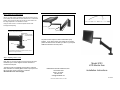
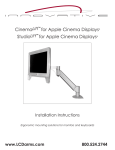
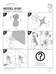
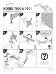
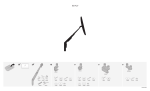
LCD Monitor Arm
Model No. 9103
Step 2 Attaching the Tilter to the Adapter Bracket
Carefully remove the base from the flat panel monitor. For removal
instructions, see your Flat Panel User’s Guide.
INSTRUCTIONS
The IOP Monitor Arm Model 9103 comes in three parts.
Each component is sold separately.
1. Mount assembly (instructions enclosed separately)
2. Monitor Arm assembly
3. Adapter Bracket
If the adapter bracket is already attached to the tilt mechanism,
skip this step and continue with step 3.
Slide the titler shaft into the hole in the end of the forearm, as
shown in Illustration 4 below.
If the adapter bracket is not attached to the tilt mechanism, attach it
using the (4) 1/4-20 x 1/2 Philips Pan Head Screws as shown
below in Illustration 2.
Adapter Bracket
Tilter Shaft
The Monitor Arm is easily assembled following these simple
steps.
Forearm
1/4-20 x 1/2
Screws
Be sure the mount is securely fastened to the surface
before beginning.
Step 1 Attaching the Arm to the Mount
NOTE: If the bracket does not line up with the hole
pattern on the back of your monitor, please
contact our customer service department.
Tilt
Mechanism
Illustration 4
Once the mount is secure, insert the shaft of the LCD Arm into the
mount as shown below in Illustration 1 (Mounts will vary).
Fine Tuning Your Arm
Illustration 2
Step 3 Attaching the Adapter Bracket to the Flat Panel
Arm
Assembly
Align the tilter and adapter bracket with the hole pattern on the
back of your LCD. Use the (4) four M4-12 Philips Pan Head
Screws to attach the plate to the back of the monitor. See the
lllustration 3 below.
Step 1 Adjusting the Tilt Friction
Tilt the monitor to the preferred angle of viewing and tighten the
Friction Knob.
Be sure the LCD tilts with resistance.
Friction Knob
Not enough friction may cause
the monitor to fall forward
without stopping, possibly
damaging your monitor.
Illustration 1
Illustration 3
Step 2 Setting the Counter-balance
Use the 1/4” allen wrench (provided), insert into the hole on the top
of the endcap with shaft; with one hand, hold the arm in a horizontal
position, while turning the allen wrench with the other hand to set
the weight adjustment. See Illustration 5 below.
Using the allen wrench in a horizontal position allows extra
leverage while adjusting.
(1) Forearm
(2) Pivot Point
To increase the weight for heavier monitors, turn
the wrench left (counter-clockwise).
1/4” Allen Wrench
Horizontal Position
Endcap
Mount
(3) Mount Base
Illustration 6
All product returns require a Return Authorization (R/A)
Number. If you need to return your product for any reason,
please call 800-524-2744 to obtain your R/A or if you require
additional assistance with this product.
To decrease the resistance for lighter monitors, turn the
wrench to the right (clockwise).
Illustration 5
Step 3 Adjusting Friction Joints
Each joint on your new monitor arm has a built in set screw
that allows you to set the degree of friction and ease of
movement of that joint.
The friction joints are located (1) in the forearm, where the
tilter mechanism is inserted, (2) the forearm’s pivot point and
(3) mount base, where monitor arm is inserted.
See Illustration 6 on the next page.
Model 9103
LCD Monitor Arm
INNOVATIVE OFFICE PRODUCTS, INC.
100 Kuebler Road
Easton, PA 18042
800-524-2744
[email protected]
Installation Instructions
IOP-502572
© Innovative Office Products, Inc. 2003