1
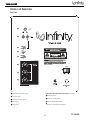
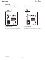
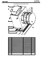
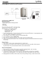
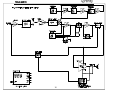
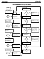
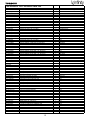
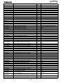
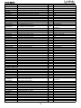
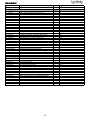
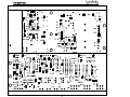
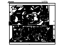
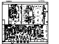
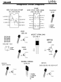
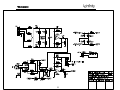
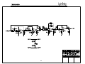
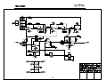
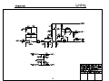
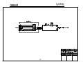
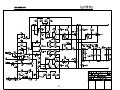
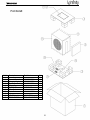
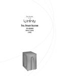
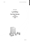
TSS-SUB4000
SERVICE MANUAL
Infinity Systems Incorporated
250 Crossways Park Dr.
Woodbury, New York 11797
Rev0 3/2005
TSS-SUB4000
CONTENTS
BASIC SPECIFICATIONS . . . . . . . . . ………………………………………….1
DETAILED SPECIFICATIONS . . . . . . . . . . . ………………………………….2
CONTROLS. ………………….. .. . …………………………………... . . . . . . .4
CONNECTIONS . . . . . . . . . . . ……….………………………………..…. . . . 5
OPERATION……. . . . . .. . . . . . . . .. .. . . . .. .. . . . . ….……… . . ... . . . . . . .6
EXPLODED VIEWS-MECHANICAL PARTS LIST….… . … . .. . . .. . … . ….7
TEST SET-UP & PROCEDURE……………………….. .. .. . . …………….. .9
BLOCK DIAGRAM. . . . ………………... ………………………………… . … . 10
TROUBLESHOOTING FLOW CHART…………………….…………………….11
SERVICE NOTE - POWER TRANSFORMER…………………….…………12
ELECTRICAL PARTS LIST …………………… ………………..………………13
PCB DRAWINGS. . . ………………... …………………………………………..17
IC – TRANSISTOR PINOUTS . … . . .. . . . . . ………………………….... . . . 20
SCHEMATIC DIAGRAMS (120v). . ………………………………………..…. . .21
PACKAGING. ………………….. .. . ……… ………………………... . . . . . . 31
SPECIFICATIONS
Frequency Response
28Hz – 150Hz (–3dB)
24Hz – 180Hz (–6dB)
Maximum Amplifier Output
400 watts RMS
(20Hz – 150Hz with no more than 0.1% THD)
Crossover Frequency
150Hz, 12dB/octave
Driver
12" (305mm) MMD®
Dimensions (H x W x D)
17-1/2" x 17-1/4" x 11-1/8"
(445mm x 438mm x 283mm)
Weight
48 lb (21.8kg)
Infinity continually strives to update and improve existing products, as well as create new ones. The specifications and
construction details in this and related Infinity publications are therefore subject to change without notice.
1
TSS-SUB4000
TSS-4000 subwoofer 300W Powered Sub/ Plate Amp
LINE VOLTAGE
US 120vac/60Hz
EU 230vac/50-60Hz
Asia 100vac/50Hz
Parameter
Amp Section
Type (Class AB, D, other)
Load Impedance (speaker)
Rated Output Power
THD@ Rated Power
THD @ 1 Watt
DC Offset
Damping factor
Input Sensitivity
Line/Hi Level Input Phase
Line Input
Speaker/Hi Level Input
Yes/No
Yes
No
No
Hi/Lo Line
108-132
207-264
90-110
Nom.
120
230
100
Unit
Vrms
Vrms
Vrms
Specification
Unit
QA Test
Limits
Conditions
D
4
300
1
0.5
undefined
20
--Ohms
Watts
%
%
mV-DC
N/A
N/A
370 mV mVrms
N/A
Signal to Noise
SNR-A-Weighted
SNR-unweighted
SNR rel. 1W-unweighted
100 dBA
70 dBr
60 dBr
Residual Noise Floor
2 mVrms
Residual Noise Floor
1 mVrms(max)
< 20
> 15
Notes
Normal Operation
Normal operation, MOMS required
Normal Operation
Notes
Nominal
Regulated 120 V line
22k filter, 50Hz
22k filter, 50Hz
@ Speaker Outputs
Z-curve required
5% tollerance applies
300W +/- 5%
300 W @ 50Hz
1 input driven
measured at 50 Hz
relative to rated power
A-Weighting filter
relative to rated power
22k filter
relative to 1W Output
22k filter
Volume @max, using RMS
reading DMM/VOM (or A/P)
Volume @max, w/ A/P Swept
Bandpass Measurement (Line
freq.+ harmonics)
Input Impedance
Line Input
Speaker/Hi Level Input
Active Filters
Low Pass (fixed or
variable)
Frequency
Slope
Q
Subsonic filter (HPF)
Frequency
Slope
Q
Line Out Filter (HPF)
Frequency
Slope
Q
Friend Circuit
Frequency
Slope
Q
Video Boost
Boost
Range
Special filter
Switches
Main Power ON/OFF
Rabos ON/OFF
Polarity Switch
Limiter (yes/no)
Type
Type
Type
10 k ohms
N/A
FIXXED
--
130 Hz
24 dB/Octave
Butterworth
-fixed
-35 Hz
12 dB/Octave
1.2
-NONE
-Hz
dB/Octave
-FIXXED
-66 Hz Hz
6 dB/Octave
1.2
-NONE
-dB
Hz
RABOS
--
rocker
YES
YES
mini togle
YES
mini togle
Nominal
-------
notch filter
Located on amp plate
TV-5
Located on amp plate
"Off": 0°; "On": 180°
Located on amp plate
YES
compressor and limiter
2
TSS-SUB4000
Parameter
Specification
THD at Max. Output Power
Output Volume Control
Volume Control Pot
Detent (center/#)
Taper (lin/log)
@ minimum setting
Unit
less than 10 %
YES
NO
log A taoer
no output
Input/Output Phase
Line Input vs. Hi Input
Lo/Hi Input vs. Lo/Hi Output
Stereo
YES
Signal Sensing (ATO)
Auto-Turn-On (yes/no)
ATO Input Test Frequency
ATO Input Threshold
ATO Low Pass cutoff
Maximum Output Power
----
mounted on amp panel
---
RCA phono jack, gold plated
Shared with "R" Line In jack
YES
-100 Hz
2 mV
400 Hz
ATO Turn-on time
1 ms
Auto Mute / Turn-OFF Time
10 minutes
YES
ATO
AC Power Applied
Bi-color LED located on front of
cabinet
ATO mode only
--
green / red color
--
color
"Active": green; "Standby": red
5 mV-peak
30 mV-peak
30 mV-peak
Efficiency
Stand-by Input Power
AC Power Cons.@1W
10 Watts
12 Watts
typ.
typ.
@ nom. line voltage
@ nom. line voltage
473 Watts
typ.
@ nom. line voltage
typ.
@ nom. line voltage
Efficiency
63 %
@ Speaker Output
@ Speaker Output
@ Speaker Output
Protection
Short Circuit Protection
YES
--
Direct short at output
Thermal Protection
YES
--
threshold ~ 65 deg. C at panel
DC Offset Protection
YES
--
Line Fuse Rating ( 120 V )
3.15 Amps
DC present at Speaker Out
leads
Type ADL or MDL
AC Power & Transformer
Power cord length
Maximum THD as a result of limiting.
LPF "On", BOS "Off"
ATO-LPF for noise immunity
LPF "On", BOS "Off"
Amp connected and AC on,
10
then input signal applied ( 1 W
output )
Time before muting, after signal
5 < t < 15
is removed
Transients/Pops
ATO Transient
Turn-on Transient
Turn-off Transient
Power Cons.@rated power
Notes
typ.
450
greater than 2 sec.
Power on LED
Normal On/Off
Conditions
N/A °
N/A °
Input/Output
Line In (L,C,R,AC3,Mono)
LFE In
Power on Features
Power on Delay time
QA Test
Limits
9 feet
Double insulated cord,
AWG#18
3
AC Line cycled from OFF to ON
AC Line cycled from ON to OFF
Input power measured is REAL Watts, not VA
Relay for driver/fire protection
Fuse holder on inside surface of amp panel
TSS-SUB4000
CONTROLS AND CONNECTIONS
Rear Panel
¡
™
£
¢
§
¶
∞
•
ª
¡ Subwoofer Level (Volume) Control
Room Adaptive Bass Optimization System Controls (see page 5)
™ Line-Level Inputs
§ R.A.B.O.S. Selector
£ Normal/LFE Low-Pass Selector
¶ R.A.B.O.S. Level Adjustment
¢ Phase Switch
• R.A.B.O.S. Bandwidth Adjustment
∞ Power Switch
ª R.A.B.O.S. Center-Frequency Adjustment
4
TSS-SUB4000
TSS-SUB4000
CONNECTIONS
If you have a Dolby* Digital or DTS® receiver/processor
with a low-frequency-effects (LFE) output:
If your receiver/processor has subwoofer
outputs for the left and right channels:
• Set Low-Pass Switch to Off.
• Set Low-Pass Switch to On.
NOTE: In this case, you do not need to use a Y connector. Simply
connect the LFE output on your receiver/processor to either the
left or right input on the subwoofer.
NOTE: Some receivers have a single subwoofer output (do not confuse
this with a single LFE output as described to the left). In that case,
it is recommended that you use a Y connector (not included) to maximize
performance.
TSS-SUB4000
5
TSS-SUB4000
OPERATION
Power On
Low-Pass Selector
Plug your subwoofer’s AC cord into a wall outlet. Do not use the
outlets on the back of the receiver.
If you have a Dolby Digital or DTS processor/receiver, the
Crossover Frequency is set by the processor/receiver. Consult
your owner’s manual to learn how to view or change this setting.
In this case, the Low-Pass Selector £ should be set to “Off”.
We strongly recommend this setup method.
Initially set the Subwoofer Level (Volume) Control ¡ to the
“min” position.
Turn on your sub by pressing the Power Switch ∞ on the
rear panel.
When this switch £ is in the “On”position, the subwoofer will
reproduce frequencies below 150Hz.
Auto On/Standby
With the Power Switch ∞ in the ON position, the Power
Indicator LED on the front of the subwoofer will remain backlit in
red or green to indicate the On/Standby mode of the subwoofer.
Phase Control
The Phase Switch ¢ determines whether the subwoofer
speaker’s piston-like action moves in and out with the main
speakers, 0,˚ or opposite the main speakers, 180˚. Proper phase
adjustment depends on several variables such as room size,
subwoofer placement and listener position. Adjust the phase
switch to maximize bass output at the listening position.
RED = STANDBY (No signal detected, Amp Off)
GREEN = ON (Signal detected, Amp On)
The subwoofer will automatically enter the Standby mode after
approximately 10 minutes when no signal is detected from your
system.The subwoofer will then power ON instantly when a
signal is detected. During periods of normal use, the Power
Switch ∞ can be left on.You may turn off the Power Switch ∞
for extended periods of nonoperation, e.g., when you are away
on vacation.
Adjust Gain
Turn on your entire audio system and start a CD or movie
soundtrack at a moderate level.Turn up the Subwoofer Level
(Volume) Control ¡ about halfway. If no sound emanates from
the subwoofer, check the AC-line cord and input cables. Are the
connectors on the cables making proper contact? Is the AC
plug connected to a “live” receptacle? Has the Power Switch ∞
been pressed to the “On” position? Once you have confirmed that
the subwoofer is active, proceed by playing a CD, record or
cassette. Use a selection that has ample bass information.
Set the overall volume control of the preamplifier or stereo to a
comfortable level. Adjust the Subwoofer Level (Volume) Control ¡
until you obtain a pleasing blend of bass. Bass response should
not overpower the room but rather should be adjusted so there
is a harmonious blend across the entire musical range. Many
users have a tendency to set the subwoofer volume too loud,
adhering to the belief that a subwoofer is there to produce lots
of bass.This is not entirely true. A subwoofer is there to enhance
bass, extending the response of the entire system so the bass
can be felt as well as heard. However, overall balance must
be maintained or the music will not sound natural. An
experienced listener will set the volume of the subwoofer so
its impact on bass response is always there but never obtrusive.
6
TSS-SUB4000
TSS-SUB4000 EXPLODED VIEW
Ref #
1
2
3
4
5
6
7
8
9
10
11
12
13
14
Not
Shown
Description
Part Number
Qty
Grille
Woofer/Trim Ring Screw
Trim Ring
Woofer 12" (305mm) MMD
Port Tube
TSS-SUB4000 Amplifier
Amplifier Screw
TSS-SUB4000 Cabinet
Rubber Foot
Foot Screw
Gasket
LED
Plastic Plate
Aluminum Plate
Power Transformer
329-120-05097-0VA
351-AM04030A893
213-120-05033-0BA
30PR14BW-DW01
249-HIPS-05021-0VA
Not for Sale
352-FM04020D605
Not for Sale
320-RUB-05030-0BA
352-CM04025D604
333-EVA-05091-0WA
166-A055A8GX
Not Serviceable
Not Serviceable
150-R1107008
1
8
1
1
1
1
12
1
4
4
1
1
1
1
1
7
TSS-SUB4000
Ref #
1
2
3
4
5
6
7
8
9
10
11
Description
Part Number
Qty
Screw
Damping
Main Mounting Bolt
Tube Gasket
Rubber
Gasket
Rubber Gasket
Damping
Power Transformer
Nut
Damping
352-CM03530D926
11
1
1
2
1
2
1
1
1
1
1
398-RUB-05093
336-RUB-05013
150-R1107008
8
TSS-SUB4000
TSS-SUB4000 Test Set Up and Procedure
SYSTEM AURAL SWEEP TEST
Equipment needed:
• Function/signal generator/sweep generator
• Multimeter
• RCA cables
General Unit Function (UUT = Unit Under Test)
Switches/knobs on the amplifier faceplate:
Phase switch – either position
Low Pass switch – Off
RABOS switch – Off
1. From the signal generator, Connect both right and left line level inputs (RCA jacks) – to signal generator and
UUT. Use Y-cable if necessary from mono source.
2. On the amplifier, turn the LEVEL control full Counterclockwise (Min).
3. Turn on generator, adjust to 125mV, 50 Hz.
4. Plug in UUT; turn the power switch ON. Turn LEVEL control full Clockwise (Max).
5. LED (on front panel) should now be Green; immediate bass response should be heard and felt from rear port
tube opening.
Sweep Function
1. Follow steps 1-5 above, using a sweep generator as a signal source.
2. Sweep generator from 20Hz to 1kHz. Listen to the cabinet and drivers for any rattles, clicks, buzzes or
any other noises. If any unusual noises are heard, remove woofer and test.
Driver Function (Woofer)
1. Remove woofer from cabinet (follow steps on exploded view page); detach + and - wire clips.
2. Check DC resistance of woofer; it should be 3.5 ohms±10%.
3. Connect a pair of speaker cables to driver terminals. Cables should be connected to an integrated
amplifier fed by a signal generator. Turn on generator and adjust so that speaker level output is 5.0V.
4. Sweep generator from 20Hz to 1kHz. Listen to driver for any rubbing, buzzing, or other unusual noises.
9
TSS-SUB4000
10
TSS-SUB4000
TSS-Sub4000 Testing Flow Chart
yes
Start
Test protection
Dc voltage check
±Vcc,±15V
no
OK
no
OK
Check U107.R237
±15Vcc ect
yes
Check transformer
C168,C169,D123,
D124,C170
Test limiter circuit
yes
no
Power on check
LED red &blue
OK
Check U106.Q107ect
yes
no
OK
Check vol module
& connector
cable& ±15V.ect
Check THD output
power, noise
yes
no
OK
Test frequency
Response
yes
no
OK
Auto off Function
Hi pot test
Check U102,R124,
C104,R125,C117.ect
yes
no
OK
Test phase sw,low
pass sw rabos vr
yes
Listening test
no
Check sw103,102,
R158,163,177 ect
OK
no
OK
yes
yes
Test input sensitivity
The Amp ass’y ok
END
no
OK
Check pre board
& power board ,
±Vcc,±15V ect
Check U101,R117,
R112,R114 ect
11
Check U103.Q101.
Q102.C131.R142;Ac
cord, Transformer.
TSS-SUB4000
NOTICE
The main power transformer (toroid) part# 150-r1107008 in the TSS-SUB4000 is
not mounted in the amplifier inside the amp cover, but mounted in the cabinet in a
separate location.
Replacement:
To replace the power transformer, it is necessary to remove the woofer from the cabinet.
The mounting bolt and transformer itself is mounted on an internal brace; both are
accessible through the woofer opening. Instructions for woofer removal can be found on
the exploded view, page 7.
Troubleshooting:
To keep the circuit “live” while exposing the amplifier components, the amplifier cannot
completely be removed and powered up outside the cabinet due to the power
connections to the externally mounted transformer. Instead, an alternate method is to
leave the amp cover in place and remove the four Phillips screws holding the amp ass’y
to the amp cover. Then the amplifier can be partially removed for access, while
maintaining the power connections. Unplugging the LED connection (red/black wires) at
the PCB plug will allow the amp to be removed even further.
12
TSS-SUB4000
TSS-SUB4000 120V Electrical Parts List
Part Number
Description
Qty
Reference Designator
MAIN PCB
Resistors
110-12621j15
110-16102j26
110-16103j26
110-16153j26
110-16182j26
110-16222j26
110-16223j26
110-16274j26
110-16333j26
110-16391j26
110-16432j26
110-16472j26
110-16473j26
110-16683j26
122-14101j26
116-141r00j26x
116-161001f26
116-161002f26
116-161022f26
116-161301f26
116-161822f26
116-162001f26
116-162492f26
116-164320f26
116-166813f26
110-20152j20
113-500r1j10
116-142003f26
Resistor 620Ω1/2W ± 5% 15mm
Resistor 1K 1/6W ± 5% CF 26mm
Resistor 10K 1/6W ± 5% CF 26mm
Resistor 15K 1/6W ± 5% CF 26mm
Resistor 1.8K 1/6W ± 5% CF 26mm
Resistor 2.2K 1/6W ± 5% CF 26mm
Resistor 22K 1/6W ± 5% CF 26mm
Resistor 270K 1/6W ± 5% CF 26mm
Resistor 33K 1/6W ± 5% CF 26mm
Resistor 390Ω1/6W CF 26mm
Resistor 4.3K 1/6W ± 5% CF 26mm
Resistor 4.7K 1/6W ± 5% CF 26mm
Resistor 47K 1/6W ± 5% CF 26mm
Resistor 68K 1/6W ± 5% CF 26mm
fusible Resistor 1/4W 100ohm 5%
metal film Resistor 1.00Ω1/4W ± 5% MO 26mm
metal film Resistor 1K 1/6W ± 1% MF 26mm
metal film Resistor 10K 1/6W ± 1% MF 26mm
metal film Resistor 10.2K 1/6W MF 26mm
metal film Resistor 1.30K 1/6W MF 26mm
metal film Resistor 18.2K 1/6W ± 1% MF 26mm
metal film Resistor 2.00K 1/6W ± 1% MF 26mm
metal film Resistor 24.9K 1/6W ± 1% MF 26mm
metal film Resistor 432Ω 1/6W ± 1% MF 26mm
metal film Resistor 681K 1/6W ± 1% MF 26mm
Resistor 1.5K 2W ± 5% CF 20mm KINK
cement Resistor 0.1Ω5W ± 5%
metal film Resistor 200K 1/4W ± 1% MF 26mm
1
3
9
2
1
2
3
1
1
2
1
4
1
1
2
2
2
2
1
3
1
1
2
1
1
1
2
1
R238
R210,R239,R264
R227,229,230,231,232,233,260,261,263
R247,R249
R248
R242,R245
R218,R220,R223
R240
R211
R243,R246
R254
R217,219,222,213
R221
R212
R241,R244
R256,R255
R252,R253
R234,R235
R251
R226,R228,R236
R214
R215
R257,R258
R265
R262
R208
R224,R225
R209
disc Capacitor 1000P 50V ± 10%
disc Capacitor 0.1U 50V +80/-20%
disc Capacitor 100P 50V ±5%
electrolytic Cap 100uF 16V ±20%
electrolytic Cap 22U 50V ±20%
electrolytic Cap 220U 10V ±20%
low leakage ec 220uF 16V ± 20%
multylayer Cap 10nF 100V X7R 10%
multylayer Cap 47nF 200V X7R ± 10%
electrolytic Cap 2200uF 35V ± 20%
electrolytic Cap 6800U 80V ± 20%
1
2
2
2
2
2
1
1
2
2
2
C165
C163,C164
C159,C160
C166,C167
C161,C162
C156,C157
C155
C174
C172,C173
C170,C171
C168,C169
IC TL431CLP Shunt Regulator
Transistor 2SC1815GR NPN
Transistor 2SA1015GR PNP
Transistor FSC 2N5551 NPN
Transistor FSC 2N5401 AI-PNP 350V 500mA TO-92
diode 100mA 75V SIGNAL IN4148 ROHM
ZENER diode 5.6V 1/2W 52mm
ZENER diode 15V 1/2W 52mm
ZENER diode 20V 1/2W 52mm
Transistor HI-SINCERITY HSD669A NPN
Transistor HSB649T PNP
I.C.LM324N QUAD OP-AMP
diode 1A 200V DF02M DB103G BRIDGE
diode 10A 200V KBU1003 BRIDGE
diode 1N4002
1
4
3
1
1
7
1
1
1
1
1
1
1
1
1
D115
Q110,112,114,117
Q111,113,115
Q109
Q108
D118,119,120,121,125,126,117
D116
D122
D129
Q116
Q118
U107
D124
D123
D114
Capacitors
130-2b102k503
130-3f104z503
130-ch101j503
135-3107m16
135-3226m50
135-3227m10
139-3227m16
140-rx103ka03
140-rx473kb03
135-4228m35
135-4688m80
Semiconductors
190-161431c1p1
192-027c1815gr
192-028a1015gr
192-1572n5551
192-1582n5401
197-031n4148
199-15000565
199-15001505
199-15002005
192-991d669a
192-992b649t
190-161m324n
197-00db103g
197-00kbu1003
197-101n4002
13
TSS-SUB4000
Part Number
Description
Qty
Reference Designator
MAIN PCB
Miscellaneous
109-1tsc103j0
162-10229004
171-udhss124d
175-1c02p01
175-1c06v01
175-1d02v01
thermister TSC05103J
wire assy 220mm AWG28
relay 5A 24V UDH-SS124D
coupling 2PIN PITCH=2.5mm
coupling 6PIN PITCH=2.5mm
coupling 2PIN PITCH=3.96mm
1
1
1
1
1
1
R237
P107
K101
P108
P105
P112
110-14152j26
110-16101j26
110-16102j26
110-16103j26
110-16105j26
110-16106j26
110-16151j26
110-16154j26
110-16183j26
110-16203j26
110-16221j26
110-16223j26
110-16472j26
110-16473j26
110-16474j26
110-164r7j26
116-161000f26
Resistor 1.5K 1/4W ± 5% CF 26mm
Resistor 100Ω1/6W ± 5% CF 26mm
Resistor 1K 1/6W ± 5% CF 26mm
Resistor 1K 1/6W ± 5% CF 26mm
Resistor 1M 1/6W ± 5% CF 26mm
Resistor 10M 1/6W ± 5% CF 26mm
Resistor 150Ω1/6W ± 5% CF 26mm
Resistor 150K 1/6W ± 5% CF 26mm
Resistor 18K 1/6W ± 5% CF 26mm
Resistor 20K 1/6W ± 5% CF 26mm
Resistor 220Ω1/6W ± 5% CF 26mm
Resistor 22K 1/6W ± 5% CF 26mm
Resistor 4.7K 1/6W ± 5% CF 26mm
Resistor 47K 1/6W ± 5% CF 26mm
Resistor 470K 1/6W ± 5% CF 26mm
Resistor 4.7Ω1/6W ± 5% CF 26mm
metal film Resistor 100Ω1/6W ± 1% MF 26mm
1
4
2
9
2
1
1
1
1
1
2
2
1
1
1
1
1
116-161001f26
metal film Resistor 1K 1/6W ± 1% MF 26mm
12
116-161103f26
116-161502f26
116-161504f26
116-161622f26
116-161742f26
116-162001f26
116-162052f26
116-162211f26
116-162212f26
116-162671f26
116-163323f26
116-163400f26
116-163571f26
116-163923f26
116-164751f26
116-164752f26
116-164992f26
116-165231f26
116-165232f26
116-165400f26
116-166041f26
116-166800f26
116-168250f26
116-168661f26
116-169311f26
115-h103a101
metal film Resistor 100K 1/6W ± 1% MF 26mm
metal film Resistor 15.0K 1/6W ± 1% MF 26mm
metal film Resistor 1.5M 1/6W ± 1% MF 26mm
metal film Resistor 16.2K 1/6W ± 1% MF 26mm
metal film Resistor 17.4K 1/6W ± 1% MF 26mm
metal film Resistor 2.00K 1/6W ± 1% MF 26mm
metal film Resistor 20.5K 1/6W ± 1% MF 26mm
metal film Resistor 2.21K 1/6W ± 1% MF 26mm
metal film Resistor 22.1K 1/6W ± 1% MF 26mm
metal film Resistor 2.67K 1/6W ± 1% MF 26mm
metal film Resistor 332K 1/6W ± 1% MF 26mm
metal film Resistor 340Ω1/6W ± 1% MF 26mm
metal film Resistor 3.57K 1/6W ± 1% MF 26mm
metal film Resistor 392K 1/6W ± 1% MF 26mm
metal film Resistor 4.75K 1/6W ± 1% MF 26mm
metal film Resistor 47.5K 1/6W ± 1% MF 26mm
metal film Resistor 49.9K 1/6W ± 1% MF 26mm
metal film Resistor 5.23K 1/6W ± 10% MF
metal film Resistor 52.3K 1/6W MF 26mm
metal film Resistor 540Ω1/6W MF 26mm
metal film Resistor 6.04K 1/6W ± 1% MF 26mm
metal film Resistor 680Ω1/6W ± 1% MF 26mm
metal film Resistor 825Ω1/6W ± 1% MF 26mm
metal film Resistor 8.66K 1/6W ± 1% MF 26mm
metal film Resistor 9.31K 1/6W ± 1% MF 26mm
variable Resistor A10K LEVEL
variable Resistor RV16A01-20-15K-A10K-3E
LEVEL, RABOS WIDTH
1
2
1
1
4
1
2
1
3
1
1
2
1
1
2
2
1
2
1
1
2
1
2
1
2
1
R150
R112,R113,R151,R152
R140,R196
R118,126,129,133,136,146,149,199,156
R145,R181
R186
R139
R138
R147
R200
R119,R120
R141,R148
R144
R137
R143
R153
R154
R130,131,132,159,160,166,171,173,178,192,
114,115
R174
R162,R168
R142
R188
R124,R125,R127,R128
R202
R197,R198
R172
R193,R204,R206
R155
R195
R164,R169
R157
R201
R109,R110
R121,R122
R135
R205,R207
R190
R175
R165,R170
R176
R161,R167
R134
R189,R179
R259
2
R158,R177
1
R163
INPUT/RABOS PCB
Resistors
115-h103a203
115-h103c201
RABOS
variable Resistor RV16A01-20-15K-C10K-3E RABOS FREQ.
14
TSS-SUB4000
Part Number
Description
Qty
Reference Designator
INPUT/RABOS PCB
Capacitors
129-a102j633
129-a103j633
129-a104j633
129-a223j633
129-a224j633
129-a473j633
130-2b102k503
130-2b221k503
metalized Capacitor 0.001uF 63V ± 5% MSC
metalized Capacitor 10NF 63V
metalized Capacitor 0.1U 63V ± 5% MSC
metalized Capacitor 0.022U 63V ± 5% MSC
metalized Capacitor 0.22uF 63V ± 5% MSC
metalized Capacitor 0.047U 63V ± 5% MSC
disc Capacitor 1000P 50V ± 10%
disc Capacitor 220P 50V ± 10%
1
1
6
1
2
3
2
3
130-3f104z503
disc Capacitor 0.1U 50V +80/-20%
13
130-3f473m503
130-sl101k503
130-s1470k503
135-3105m50
135-3106m50
135-3107m16
135-3107m25
135-3226m50
139-3227m16
129-a683j633
disc Capacitor 0.047U 50V ± 20%
disc Capacitor 100P 50V SL ± 10%
disc Capacitor 47P 50V ± 10%
electrolytic Cap 1U 50V ± 20%
electrolytic Cap 10uF 50V ± 20%
electrolytic Cap 100uF 16V ± 20%
electrolytic Cap 100U 25V ± 20%
electrolytic Cap 22U 50V ± 20%
low leakage electrolytic Cap 220uF 16V ± 20%
metalized Capacitor 0.068uF 63V ± 5% MSC
1
2
1
1
4
5
1
1
1
1
C148
C183
C116,137,138,139,143,118
C150
C121,C122
C117,C119,C149
C181,C182
C107,C108,C128
C112,114,124,125,130,133,135,144,145,146,
147,153,154
C180
C110,C120
C127
C126
C109,C111,C123,C129
C113,115,132,134,136
C152
C151
C131
C142
Transistor 2SC1815GR NPN
diode 100mA 75V SIGNAL IN4148 ROHM
zener diode 8.2V 1/2W 52mm
IC.0PA 4558D DUAL OP-AMP
I.C. TL072N DUAL OP-AMP
I.C TL074CN ST QUAD OP-AMP
I.C FAIRCHILD MPF102 FET
3
7
1
2
1
3
1
Q101,Q102,Q103
D105,106,108,109,110,112,113
D130
U101,U103
U105
U102,U104,U106
Q107
TACT switch L101 T2 LO-PASS,PHASE,RABOS
RCA JACK RCA-209
coupling 2PIN PITCH=2.5mm
3
1
2
SW102,SW103,SW104
JK102
P106,P101
R2
R25,29,30,30B,7,9
R20,R20B,R22,R23
R26
R6,13,16,31,33,34,34,35,37,38,39,40,41,42,4
3,44,45,46,32
R4
R10
R24
R1,14,15,27,28
R3
R8,R11,R21
R5,R12
Semiconductors
192-027c1815gr
197-031n4148
199-15000825
190-06m4558d
190-16t1072n
190-16t1074cn
192-153mpf102
Miscellaneous
180-t000ts81
174-0rcb202vag
175-1c02p01
CLASS D AMP PCB
Resistors
118-12061001j
118-12061002j
118-120610r0j
118-12062002j
SMD Resistor 1.00K 1206 5%
SMD Resistor 10.0K 1206 5%
SMD Resistor 10.0Ω 1206 5%
SMD Resistor 20.0K 1206 5%
1
6
4
1
118-12062201j
SMD Resistor 2.20K 1206 5%
19
118-12062204j
118-12062701j
118-12063000j
118-12063301j
118-12063902j
118-12064700j
118-12064701j
112-10180j00
SMD Resistor 2.20M 1206 5%
SMD Resistor 2.70K 1206 5%
SMD Resistor 300.0Ω 1206 5%
SMD Resistor 3.30K 1206 5%
SMD Resistor 39.0K 1206 5%
SMD Resistor 470Ω 1206 5%
SMD Resistor 4.70K 1206 5%
fusible Resistor FMF 1W 18Ω5%
1
1
1
5
1
3
2
1
SMD Capacitor 100pF 50V 10% 1206 NP0
SMD Capacitor 22pF 50V 10% 1206 SMT NP0
SMD Capacitor 560pF 50V 10% 1206 NP0
SMD Capacitor 1206 Y5V 0.1uF 50V±20%
1
1
1
8
Capacitors
141-c0101k50
141-c0220k50
141-c0561k50
141-c5104m50
15
C4
C5
C6
C2,3,7,8,9,10,11,15
TSS-SUB4000
Part Number
Description
Qty
Reference Designator
CLASS D AMP PCB
141-c7223k50
141-d7104ka0
130-s1681kb03
132-104kb50
132-105kb50
SMD Capacitor 0.022uF 50V 10% 1206 X7R
SMD Capacitor 0.1uF 100V 10% 1210 X7R
disc Capacitor SL 680PF 200V
mylar Capacitor 0.1U±10% 250V LS-10.mm MD
mylar Capacitor 1uF 250V ±10%
1
4
1
1
1
C13
C12,C14,C18,C19
C20
C40
SMD I.C.TL072CDT SGS THOMSON DUAL OP-AMP
SMD Transistor 2SC2412K-T146Q/R ROHM
SMD Transistor 2SC3906K-T146R ROHM
Transistor 2SC4672(MPT3)ROHM
SMD Transistor 2SA1037K-T146Q/R ROHM
SMD Transistor 2SA1514K-T146R ROHM
Transistor FSC 2N5401 AI-PNP 350V 500mA TO-92
SMD diode RLS4148-TE11 ROHM
SMD ZENER 5.6V 5% PHILIPS BZX84-C5V6
SMD ZENER 12V 5% PHILIPS BZX84-C12
Transistor FET IRF9640 IR P-CH TO220
Transistor FET IRF640n INTERNATIONAL
1
2
2
1
2
1
1
8
2
4
2
1
IC1
Q1,Q4
Q2,Q8
Q5B
Q7,Q9
Q3
Q6B
D1,2,3,4,5,5B,6,20
Z1,Z2
Z3,Z4,Z5,Z6
Q10,Q10B
Q11
Semiconductors
190-16t1072dts
192-09124126qs
192-09139066rs
192-091sc4672
192-09210376qs
192-09215146rs
192-1582n5401
197-03r1s4148s
199-15000563s
199-15001203s
192-232irf9640
192-233f640n
Miscellaneous
122-13151k0190
122-14300k4
128-e106ma01-s
175-9f40hr2
CHOKE SA-500-280(PT1601B*151MAA)
Ferrite core LD1215*300KU±10%
non-polar ec 10uF 100V 20%
coupling 40PIN PITCH=2.54mm HR2*40
1
1
2
0.2
L1
L2
C16,C17
MISCELLANEOUS
150-r1107008
152-u602015
154-k31505t0
155-630r345b
162-10100023
162-1035d001
162-1035d002
162-50259004
162-5035d003
163-11009
166-5070a4fd
176-wjce2
180-prf1003b
193-0s4211
193-201612tr
193-201815t2
power transformer TT093040561A
line cord SVTFT-2 6FT
Fuse 3.15a 250v 30mm UL/CSA/PSE
fuse holder UL/CSA ψ6*30mm
WIRE UL/CSA 1617#22 100mm BLK
wire 1015#16 BRN/WHT 350mm 2PIN
wire 1015#16 BLK/YEL/RED 350mm 6PIN
wire 250mm AWG24
wire 2468#26AWG 2PIN RED/BLK 350mm
wire 100mm
speaker wIre 700mm #18 UL1015 #205*0.5t/#250*0.8t
wire connector &Base CE-2
Switch ROCK RF-1003-BB210 POWER
INSULATOR(INSULATION SPACER)42*11
INSULATOR T0-220 16mm*12mm
INSULATOR
16
1
1
1
1
1
1
1
1
1
4
1
1
1
1
1
2
T01
F01
for F01
P108
TSS-SUB4000
17
TSS-SUB4000
18
TSS-SUB4000
19
TSS-SUB4000
20
TSS-SUB4000
21
TSS-SUB4000
22
TSS-SUB4000
23
TSS-SUB4000
24
TSS-SUB4000
25
TSS-SUB4000
26
TSS-SUB4000
27
TSS-SUB4000
28
TSS-SUB4000
29
TSS-SUB4000
30
TSS-SUB4000
PACKAGE
Ref #
1
2
3
4
5
6
7
8
9
10
Description
Part Number
Owner’s Manual
Warranty Card
Top/Bottom Packing
Plastic Bag
RABOS Kit
Silica Gel
Outer Carton
n/a
15ft. RCA cable
TSS-SUB4000
406-000-05133
405-000-00328
431-000-05293
Qty
402-000-05237
1
1
2
1
1
3
1
166-015F011
TSS-SUB4000PLT
1
1
335852-003
31