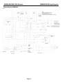
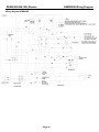
1
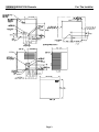
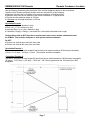
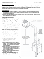
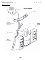
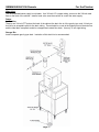
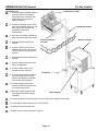
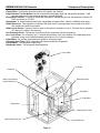
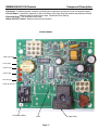
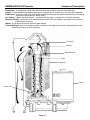
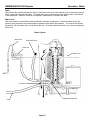
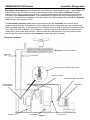
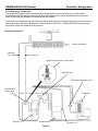
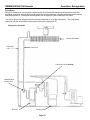
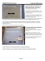
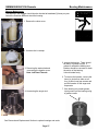
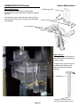
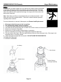
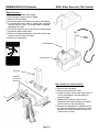
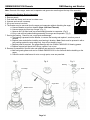
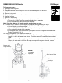
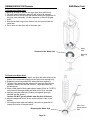
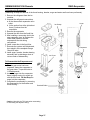
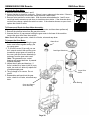
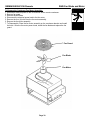
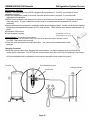
SERVICE AND INSTALLATION MANUAL
GEM Models: Remote
GEM0650R, GEM0956R, GEM1256R
Ice-O-Matic
11100 East 45th Ave
Denver, Colorado 80239
Part Number 9081350-02 17-3144-01
Pearl Ice™ Series
By Ice-O-Matic
Date 10/08
8
GEM0650/0956/1256 Remote
Introduction
How To Use This Manual
Ice-O-Matic provides this manual as an aid to the end user and service technician in installation and
maintenance of the Pearl Ice™ Series ice machines. Do not attempt to perform installation, start-up or
maintenance unless you have read and fully understand this manual.
If, at any time, you encounter conditions that are not addressed in this manual, call, E-mail or write the
Ice-O-Matic Service Department:
Ice-O-Matic
11100 E. 45th Ave.
Denver, Co. 80239
Attn: Technical Service Department
E-Mail: [email protected]
Telephone Numbers
Any Service communication must include:
800-423-3367 All Departments
• Model Number
888-349-4423
Technical Assistance Only
• Serial number
303-371-3737
• A detailed explanation of the problem
Keep this manual for future reference.
The GEM0650R, GEM0956R and GEM1256R Service Parts Manuals are available separately.
Ice-O-Matic icemakers and dispensers are not approved for outdoor installation.
WARNING: Always disconnect electrical power and shut off water supply whenever maintenance or
repairs are performed on the ice machine and related equipment.
CAUTION: Always wear protective eyewear whenever maintenance or repairs are performed on the ice
machine and related equipment
Page i
GEM0650/0956/1256 Remote
Table Of Contents
Table of Contents
Introduction ..................................................................................................................................
Table Of Contents........................................................................................................................
Freight Claim Procedure..............................................................................................................
Warranty ......................................................................................................................................
Page i
Page ii
Page iii
Page iv
For The Installer (Guidelines) ......................................................................................................
Remote Condenser......................................................................................................................
For The Installer (Remote Condenser Location) .........................................................................
For The Plumber..........................................................................................................................
Page 1
Page 6
Page 7
Page 11
For The Electrician.......................................................................................................................
For The Installer (Completed Installation)....................................................................................
For The Installer (Final Check List)..............................................................................................
Start Up........................................................................................................................................
Page 12
Page 13
Page 14
Page 15
Component Description ...............................................................................................................
Electrical Sequence .....................................................................................................................
Operation: Water .........................................................................................................................
Operation: Refrigeration ..............................................................................................................
Page 16
Page 19
Page 20
Page 21
Operation: Performance ..............................................................................................................
Sanitizing and Cleaning ...............................................................................................................
Remote Condenser Maintenance ................................................................................................
Bearing Maintenance...................................................................................................................
Page 24
Page 25
Page 26
Page 27
Sensor Maintenance....................................................................................................................
Auger Maintenance......................................................................................................................
Service Diagnosis ........................................................................................................................
Control System Diagnostics.........................................................................................................
Page 28
Page 29
Page 30
Page 32
Removal and Replacement: Water Reservoir and Bin Controls..................................................
Removal and Replacement: Bearing and Breaker ......................................................................
Removal and Replacement: Auger..............................................................................................
Removal and Replacement: Water Seal......................................................................................
Page 33
Page 34
Page 35
Page 36
Removal and Replacement: Evaporator......................................................................................
Removal and Replacement: Gear Motor .....................................................................................
Removal and Replacement: Fan Blade and Fan Motor...............................................................
Refrigeration System Service ......................................................................................................
Page 37
Page 38
Page 39
Page 40
Wiring Diagram: GEM0650R .......................................................................................................
Wiring Diagram: GEM0956R .......................................................................................................
Wiring Diagram: GEM1256R .......................................................................................................
Service History.............................................................................................................................
Page 41
Page 42
Page 43
Page 44
Page ii
GEM0650/0956/1256Remote
Freight Claim Procedure
Important!
Inspect Promptly
This merchandise has been carefully inspected and packed in accordance with the carrier’s packing
specifications. Responsibility for safe delivery has been assumed by the carrier. If loss or damage occurs, you
as the consignee must file a claim with the carrier and hold the container for carrier’s inspection.
Visible Loss or Damage
Any external evidence of loss or damage must be fully described and noted on your freight bill or express
receipt and signed by the carrier’s agent. Claim should be filed on a form available from the carrier.
Concealed Loss or Damage
If loss or damage does not appear until merchandise has been unpacked, make a written request for
inspection by the carrier within 15 days of the delivery date. Then file a claim on a form from the carrier.
File Claim Without Delay Do Not Return Damaged Merchandise to Ice-O-Matic
Page iii
GEM0650/0956/1256 Remote
Warranty
Ice-O-Matic
Parts and Labor
Domestic & International Limited Warranty
Mile High Equipment LLC (the “Company”) warrants Ice-O-Matic brand ice machines, ice dispensers, remote condensers, water filters, and ice storage
bins to the end customer against defects in material and factory workmanship for the following:
• Cube ice machines,”GEM” model compressed ice machines
,” MFI” model flake ice machines and remote condensers. Thirty-six (36) months parts and labor
• “EF” and “EMF” model flake ice machines - Twenty-four (24)
months parts and labor
• CD model dispensers - Thirty-six (36) months parts and
labor
•
Ice storage bins -Twenty-four (24) month parts and labor
•
IOD model dispensers - Twenty-four (24) months parts, Twelve (12) months
labor
Water filter systems - Twelve (12) months parts and labor (not including filter
cartridges)
•
An additional twenty-four (24) month warranty on parts (excluding labor) will be extended to all cube ice machine evaporator plates and compressors,
“GEM” model compressed ice machine compressors, and “MFI” model flake ice machine compressors from the date of original installation. An additional
thirty-six (36) month warranty on parts (excluding labor) will be extended to all “EF” and “EMF” model flake ice machine compressors from the date of
original installation. The company will replace EXW (Incoterms 2000) the Company plant or, EXW (Incoterms 2000) the Company-authorized distributor,
without cost to the Customer, that part of any such machine that becomes defective. In the event that the Warranty Registration Card indicating the
installation date has not been returned to Ice-O-Matic, the warranty period will begin on the date of shipment from the Company. Irrespective of the
actual installation date, the product will be warranted for a maximum of seventy-two (72) months from date of shipment from the Company.
ICE-model cube ice machines which are registered in the Water Filter Extended Warranty Program will receive a total of eighty-four (84) months parts
and labor coverage on the evaporator plate from the date of original installation. Water filters must be installed at the time of installation and registered
with the Company at that time. Water filter cartridges must be changed every six (6) months and that change reported to the Company to maintain the
extended evaporator warranty.
No replacement will be made for any part or assembly which (I) has been subject to an alteration or accident; (II) was used in any way which, in the
Company’s opinion, adversely affects the machine’s performance; (III) is from a machine on which the serial number has been altered or removed; or,
(IV) uses any replacement part not authorized by the Company. This warranty does not apply to destruction or damage caused by unauthorized service,
using other than Ice-O-Matic authorized replacements, risks of transportation, damage resulting from adverse environmental or water conditions,
accidents, misuse, abuse, improper drainage, interruption in the electrical or water supply, charges related to the replacement of non-defective parts or
components, damage by fire, flood, or acts of God.
This warranty is valid only when installation, service, and preventive maintenance are performed by a Company-authorized distributor, a Companyauthorized service agency, or a Company Regional Manager. The Company reserves the right to refuse claims made for ice machines or bins used in
more than one location. This Limited Warranty does not cover ice bills, normal maintenance, after-install adjustments, and cleaning.
Limitation of Warranty
This warranty is valid only for products produced and shipped from the Company after January, 2007. A product produced or installed before
that date shall be covered by the Limited Warranty in effect at the date of its shipment. The liability of the Company for breach of this
warranty shall, in any case, be limited to the cost of a new part to replace any part, which proves to be defective. The Company makes no
representations or warranties of any character as to accessories or auxiliary equipment not manufactured by the Company. REPAIR OR
REPLACEMENT AS PROVIDED UNDER THIS WARRANTY IS THE EXCLUSIVE REMEDY OF THE CUSTOMER. MILE HIGH EQUIPMENT SHALL
NOT BE LIABLE FOR ANY INCIDENTAL OR CONSEQUENTIAL DAMAGES FOR BREACH OF ANY EXPRESS OR IMPLIED WARRANTY ON THIS
PRODUCT. EXCEPT TO THE EXTENT PROHIBITED BY APPLICABLE LAW, ANY IMPLIED WARRANTY OR MERCHANTABILITY OR FITNESS
FOR A PARTICULAR PURPOSE ON THIS PRODUCT IS LIMITED IN DURATION TO THE LENGTH OF THIS WARRANTY.
Filing a Claim
All claims for reimbursement must be received at the factory within 90 days from date of service to be eligible for credit. All claims outside this
time period will be void. The model, the serial number and, if necessary, proof of installation, must be included in the claim. Claims for labor to
replace defective parts must be included with the part claim to receive consideration. Payment on claims for labor will be limited to the published labor
time allowance hours in effect at the time of repair. The Company may elect to require the return of components to validate a claim. Any defective part
returned must be shipped to the Company or the Company-authorized distributor, transportation charges pre-paid, and properly sealed and tagged. The
Company does not assume any responsibility for any expenses incurred in the field incidental to the repair of equipment covered by this warranty. The
decision of the Company with respect to repair or replacement of a part shall be final. No person is authorized to give any other warranties or to assume
any other liability on the Company’s behalf unless done in writing by an officer of the Company.
GOVERNING LAW
This Limited Warranty shall be governed by the laws of the state of Delaware, U.S.A., excluding their conflicts of law principles. The United Nations
Convention on Contracts for the International Sale of Goods is hereby excluded in its entirety from application to this Limited Warranty.
th
Mile High Equipment LLC, 11100 East 45 Avenue, Denver, Colorado 80239 (303) 371-3737
January 2007
Page iv
GEM0650/0956/1256 Remote
For the Installer
Installation Guidelines:
For proper operation of the Ice-O-Matic ice machine, the following installation guidelines must be followed.
Failure to do so may result in loss of production capacity, premature part failures, and may void all warranties.
Ambient Operating Temperatures: (Not including remote condenser)
Minimum Operating Temperature: 50°F (10°C)
Maximum Operating Temperature 100°F (38°C)
Note: Ice-O-Matic ice makers and dispensers are not approved for outdoor installation.
Incoming Water Supply
Minimum incoming water temperature: 40°F (4.5°C)
Maximum incoming water temperature: 100°F (38°C)
Minimum incoming water pressure: 20 psi (1.4 bar)
Maximum incoming water pressure: 80 psi (4.1 bar)
Note: If water pressure exceeds 80 psi a water pressure regulator must be installed.
Drains
All drain lines must be installed per local codes. Flexible tubing is not recommended. Route bin drain, vented
float overflow drain and water condenser drain individually to a floor drain. The use of condensate pumps for
draining water is not recommended by Ice-O-Matic. Ice-O-Matic assumes no responsibility for improperly
installed equipment.
Water Filtration
A water filter system should be installed with the ice machine.
Clearance Requirements
Self-contained air cooled ice machines must have a minimum of 6 inches (15cm) of clearance at the sides of
the ice machine for proper air circulation.
Stacking
Ice-O-Matic Pearl Ice™ machines are not designed to be stacked.
Dispenser Application
The Pearl Ice™ machine is approved for specific dispenser applications, reference page 4.
Electrical Specifications
Refer to the serial plate at the rear of the ice machine to make sure proper voltage and circuit breaker size
have been supplied. Make sure the machine is on a dedicated circuit. The Pearl Ice™ Series are not supplied
with an electrical power cord and will need to be installed and wired per local electrical codes.
Adjustments
Level the machine within 1/8 inch in all directions. Adjust the cabinet or bin legs as required.
Check the bin control for proper operation.
Check the water level in the reservoir for proper adjustment.
Check the water regulating valve adjustment if water cooled.
Page 1
GEM0650/0956/1256 Remote
For The Installer
GEM0650/0956R
Page 2
GEM0650/0956/1256 Remote
For The Installer
GEM1256R
Page 3
GEM0650/0956/1256 Remote
For the Installer
Bin Application
The Pearl Ice™ Series are designed to fit the following Ice-O-Matic Bins
●B42, using Bin Top KBT 24 (Note: GEM0650 and GEM0956 ONLY)
●B25, B40 B55 using Bin Top KBT 19.
●B100 using Bin Top KBT 23 (one unit) or KBT 22 (two units).
●B120, B150, B170 Not designed for Pearl Ice™ Series.
Dispenser Application
The Pearl Ice™ Series can be placed on and used with certain ice and beverage dispensers. Kits are required
for proper operation.
IOM Pearl Ice™ Accessory List
Dispenser
GEM0650
KBT15022, KGEMDIV
Ice-O-Matic IOD150
GEM0956
KBT15022, KGEMDIV
GEM1256
Does not fit
Ice-O-Matic IOD200 or
IOD250
KBT25022, KGEMBIOD
KBT25022, KGEMBIOD
KBT25030, KGEMBIOD,
KGEMDIV
Cornelius ED or DF150
KBT15022,
R629088514(Cornelius
Model)
KBT15022,
R629088514(Cornelius
Model)
Does not fit
Cornelius ED or DF200
KBT25022, KGEM200
KBT25022, KGEM200
KBT25030, KGEM200
Cornelius ED or DF250
KBT25022, KGEM250
KBT25022, KGEM250
KBT25030, KGEM250
Lancer Nugget Ready
Flavor Select
N/A
N/A
N/A
SerVend S-200, SV200, S250, SV-250
N/A
N/A
N/A
Ice Machine Specifications
Model
Number
WxDxH
(Inches)
Basic
Electrical
Condenser
Minimum Circuit
Ampacity
Maximum
Fuse Size
GEM0650R
21x24x27
115/60/1
Remote
22.5
30
208
GEM0956R
21x24x27
208-230/60/1
Remote
14.1
20
208
GEM1256R
30x24x27
208-230/60/1
Remote
17.3
25
208
Page 4
Refrigerant
Charge oz. R404
GEM0650/0956/1256 Remote
For the Installer
Location:
Ice-O-Matic ice machines are designed to be installed indoors in a controlled environment. Install the ice
machine in a location where it has enough space around it to be accessible for service. A minimum of 6 inches
must be allowed at the back for air circulation on air cooled models. Try to avoid hot, dirty and crowded
locations. Be sure that the location of the machine is within the environmental limitations.
Storage Bin:
Remove the bin packaging. Tip the storage bin on its back, using parts of the packaging to protect the exterior
finish. Remove the skid and install the legs into the threaded holes in the bottom of the bin. Turn the leg
levelers all the way in preparation for leveling later. Return the bin to the upright position.
Note: Do not push the bin into position, but lift it there. Pushing a bin, especially one with ice in it, can cause
damage to the bin legs and mounts.
Install the appropriate bin top according to the instructions provided with the bin top.
Ice machine:
The ice machine is heavy, so the use of a mechanical lift is recommended for lifting the machine high enough
to install on top of the bin. After the unit is placed on the bin, line it up so it is even with the back side. Secure
the ice machine to the bin with the hardware provided with the ice machine. Remove the front panel and
remove any shipping blocks or packaging material.
Proper functioning of the bin door requires the bin door, when it is opened, to be in a stable position. If the ice
machine is too far forward on the bin, the opened door may not be stable, resulting in an unexpected closing of
the bin door.
If the ice machine is to be mounted on a bin or dispenser other than an Ice-O-Matic, refer to the manufacturer’s
instructions for machine mounting. Ice-O-Matic will not be responsible for damage or injury that results from
unexpected closing of the bin door as a result of the ice machine being too far forward on the bin.
Water Limitations:
An ice machine is a food manufacturing plant: it takes a raw material, water and transforms it into a food
product, ice. The purity of the water is very important in obtaining pure ice and maximizing product life. This
section is not intended as a complete resource for water related questions, but it does offer these general
recommendations:
●Check with a water treatment specialist for a water test and recommendations regarding water filters and
treatment.
●In most cases, the water used to make ice should be filtered or treated, depending upon the water.
There is no one type of water filter that is effective in all situations. That is why a water test is important.
RO Water Limitations:
Water conductivity must be no less that 35 microSiemens/cm.
Notice:
Ice-O-Matic ice machines are designed and manufactured with the highest regard for safety and performance
and meet or exceed the standards of UL, NSF and CUL.
Ice-O-Matic assumes no liability or responsibility of any kind for products manufactured by Ice-O-Matic that
have been altered in any way, including the use of any part and/or other components not specifically approved
by Ice-O-Matic.
Ice-O-Matic reserves the right to make design changes and/or improvements at anytime. Specifications and
design are subject to change without notice.
Page 5
GEM0650/0956/1256 Remote
Remote Condenser
ERC Dimensions (Inches)
GRC1001
GRC1061
GCR2061
A
B
C
D
E
F
G
H
Pearl Ice™ Number
33.36
10.75
23.81
2.04
6.12
16.73
11.65
19.57
GEM0650R
33.36
10.75
23.81
2.04
6.12
16.73
11.65
19.57
GEM0956R
33.36
10.75
23.81
2.04
6.12
16.73
11.65
19.57
GEM1256R
Line Sets
RT325404
RT340404
RT345404
RT360404
25 Foot Precharged Line Set
40 Foot Precharged Line Set
45 Foot Precharged Line Set
60 Foot Precharged Line Set
Page 6
GEM0650/0956/1256 Remote
Remote Condenser Location
Use the following for planning the placement of the remote condenser relative to the ice machine.
Location Limits: Remote condenser location must not exceed ANY of the following:
● Maximum rise from the ice machine to the remote condenser is 35 physical feet.
● Maximum drop from the ice machine to the remote condenser is 15 physical feet.
● Physical line set maximum length is 100 feet.
● Calculated line set length maximum is 150 feet.
Calculation Formula
● Drop = dd x 6.6 (dd= distance in feet)
● Rise = rd x 1.7 (rd = distance in feet)
● Horizonal Run = hd x 1 (hd = distance in feet)
● Calculation: Drop(s) + Rise(s) + Horizontal Run = dd+rd+hd=Calculated Line Length
Configurations that do NOT meet these requirements must receive written authorization from
Ice-O-Matic. This includes multipass or rack system remote condensers.
Do NOT:
● Route a line set that rises, then falls, then rises.
● Route a line set that falls, then rises, then falls.
Calculation Example 1:
The remote condenser is to be located 5 feet below the ice machine and then 20 feet away horizontally.
(5 feet x 6.6=33 feet) + (20 feet) = 53 feet. This location would be acceptable.
Calculation Example 2:
The remote condenser is to be located 35 feet above the ice machine and then 100 feet away horizontally.
(35 feet x 1.7=59.5 feet) + (100 feet) = 159.5 feet. 159.5 feet is greater than the 150 maximum is NOT
acceptable.
Page 7
GEM0650/0956/1256 Remote
For the Installer
Remote Condenser Location:
Limited to a 25 foot or a 40 foot length of precharged refrigerant tubing connecting the ice machine to the
remote condenser. The remote condenser must be above or level with the ice machine. Select the best
available location, protecting the remote condenser from extremes of dirt, dust and sun. Meet all applicable
building codes. Usually the services of a licensed electrician are required.
Roof Attachment:
1. Install and attach the remote condenser to the roof of the building, using the methods and practices of
construction that conform to the local building codes, including having a roofing contractor secure the
remote condenser to the roof.
2. Have an electrician connect the remote condenser fan motor wires to the ice machine, using the junction
box at the back of the ice machine.
Precharged Line Set Routing
CAUTION: Do not connect the precharged
tubing until all routing and forming of the
tubing is complete. See the coupling
instructions for connecting information.
1. Each set of precharged tubing refrigerant lines
consists of a 3/8 diameter liquid line and a 1/2
inch diameter discharge line. Both ends of
each line have quick connect couplings, one
end has a Schrader valve connection, that end
goes to the condenser.
Note: The openings in the building ceiling or
wall, listed in the next step, are the minimum
sizes recommended for passing the refrigerant
lines through.
2. Have the roofing contractor cut a minimum
hole for the refrigerant lines of 1.750 inch.
Check local codes, a separate hole may be
required for the electrical power to the
condenser.
CAUTION: DO NOT KINK OR CRIMP
REFRIGERANT TUBING WHEN
INSTALLING IT.
3. Route the refrigerant lines through the roof
opening. Follow straight line routing whenever
possible. Any excess tubing MUST remain
within the building.
4. Spiral the excess length of precharged tubing
inside the building. Use a horizontal spiral
(does not need to be as tight as illustrated) to
avoid any traps in the lines.
5. Have the roofing contractor seal the holes in
the roof per local codes.
CAUTION: The couplings on the sets of
precharged lines are self sealing when
installed properly. Carefully follow the
instructions:
Page 8
GEM0650/0956/1256 Remote
For the Installer
Typical Installation
REMOTE CONDENSER
ICE MACHINE
Page 9
GEM0650/0956/1256 Remote
For the Installer
Coupling Instructions:
Initial Connections:
1. Remove the protector caps and plugs. Wipe the seats and threaded surfaces with a clean cloth to be
certain that no foreign matter remains on them.
2. Lubricate the inside of the couplings, especially the O-Rings with refrigerant oil.
3. Position the fittings on the correct connections on the remote condenser
and ice machine.
●The 1/2 inch discharge line (Schrader valve end) goes to the remote
condenser fitting marked “Discharge Line”
●The 3/8 inch liquid line (Schrader valve end) goes to the remote
condenser fitting marked “Liquid Line”.
●The 1/2 inch discharge line goes to the ice machine fitting marked
“Discharge Line”.
●The 3/8 inch liquid line goes to the ice machine fitting marked “Liquid
Line”.
Final Connections:
4a. Begin by tightening the couplings together by hand. Continue to turn the swivel nuts by hand until it is
certain that the threads are properly engaged.
4b. Using two wrenches, one to rotate the swivel nut and one to hold the tubing, tighten each coupling.
It is CRITICAL that ONLY the NUT on the precharged tube be turned or
the diaphragms will be torn loose by the piercing knives and be loose in
the refrigeration system causing severe operational problems.
Note: As the coupling is tightened, the diaphragms in the quick connect
couplings will begin to be pierced. As that happens, there will be
increased resistance to tightening the swivel nut.
4c. Continue tightening the swivel until it bottoms out or a very definite
increase in resistance is felt (no threads should be showing). Do NOT
over tighten.
5. Using a marker or pen, mark a line lengthwise from the coupling union nut
to the bulkhead. Then tighten the coupling and additional 1/4 turn. As
the nut turns, the line will show when the 1/4 turn is made.
6. After all connections are made, and after the king valve has been opened
(do not open at this time) check the couplings for leaks.
Page 10
GEM0650/0956/1256 Remote
For the Plumber
Water Inlet:
The recommended water supply is cold water. Use 3/8 inch O.D. copper tubing, connect to the 3/8 inch male
flare on the back of the cabinet. Install a hand valve near the machine to control the water supply.
Drains:
Ice Machine:
There is one 3/4 inch FPT drain at the back of the cabinet; the drain line is of the gravity type, and 1/4 inch per
foot fall is an acceptable pitch for the drain tubing. There should be a vent at the highest point of the drain line,
and the ideal drain receptacle would be a trapped and vented floor drain. Use only ¾ inch rigid tubing.
Storage Bin:
Install a separate gravity type drain. Insulation of this drain line is recommended.
Page 11
GEM0650/0956/1256 Remote
For the Electrician
INSTALLATION MUST CONFORM TO ALL APPLICABLE CODES.
Connect the electrical power to the unit to the wires in the junction box at the rear of the machine. Check the
nameplate (located on the back panel) for the voltage requirements, and for the minimum circuit ampacity.
The machine requires a solid chassis to earth ground wire.
Connect the ice machine to its own electrical circuit so it is individually fused. Voltage variation must remain
within design limitations, even under starting conditions.
There is a separate junction box for the remote condenser fan motor. Install an interconnecting wire between
the remote condenser and the junction box at the back of the ice machine.
The remote condenser must be wired to the ice machine in accordance with local and national electrical codes
with a minimum of 18 AWG. wire with a ground bonding wire connected to the ground screw provided in both
the condenser and machine field wiring boxes. All outdoor wiring must be in rainproof conduit.
All external wiring must conform to national, state and local electrical codes. The use of a licensed
electrician is required to perform the electrical installation.
Page 12
GEM0650/0956/1256 Remote
For the Installer
Completed Installation
A typical installation should generally
appear as illustrated below. The
best place for the remote condenser
is above the ice machine, although
other locations are permissible.
Roof Cut-A-Way
Page 13
GEM0650/0956/1256 Remote
For the Installer
Final Check List
___1. Is the ice system installed indoors in
a location where air and water
temperatures are controlled, and
where they do not exceed the
design limitations?
Condenser Leveled?
___2. Is there an electrical service within
sight of the installed machine? Has
the voltage been checked, and
compared to nameplate
requirements?
Roof Holes Sealed?
___3. Have all the plumbing connections
been made and checked for leaks?
___4. Has the machine and bin been
leveled?
Remote condenser
secured?
___5. Is there a minimum of 6 inches
clearance at the rear, left and right
of the machine for proper service
access?
___6. Is the water pressure a minimum of
20 psig?
___7. Has the machine been secured to
the bin or dispenser?
___8. Is there a water shut off valve
installed near the machine?
Plumbing?
___9. Is the remote condenser installed
per local codes, and in a place
where it has adequate ventilation
and minimal solar heat gain?
___10. Has all shipping material and
literature (inside front panel) been
removed from the units?
___11.Have the remote condenser and
pre-charged lines been properly
installed?
Power Supply?
___12. Has the electrical connection between the ice maker and condenser been made?
___13. Verify that the master switch is in the OFF position.
___14. Switch ON the electrical power.
___15. Refer to the Pre-Start instructions, Page 15
Page 14
Machine Leveled?
GEM0650/0956/1256 Remote
Start Up
Pre-Start Inspection:
1. Remove the front and side service panels.
2. Check that any shipping blocks have been removed.
3. Inspect the interior of the ice machine for loose screws or wires.
4. Check that no refrigerant lines are rubbing each other.
5. Check that the fan blades turn freely (Remote Condenser).
6. Check that the refrigerant lines are properly installed.
7. Check that the electrical power has been on for at least 4 hours and that the compressor dome is
warm.
8. Check that the unit is installed correctly according to the final check list.
Start Up:
1. Go through the pre-start inspection.
2. Open the hand valve, observe that water enters the water reservoir, fills the tube from the water
reservoir to the evaporator and then shuts off. (Water cooled only, Turn the water supply ON to the
water cooled condenser). Check for leaks.
3. Open the King Valve.
4. Switch the master switch ON. The electrical start up sequence in automatic.
a. There should be a short (15 second) delay before the gear motor starts and the liquid line
opens.
b. After the liquid line opens, the low pressure control will close and the compressor will start.
5. The remote condenser fan turns, and the condenser begins to discharge warm air.
6. The unit should soon be making ice, if desired; the low side pressure may be checked: it should be 32
psig +/- 2 psig.
The air cooled discharge pressure will depend upon air and water temperatures, but should be between
200 psig and 280 psig.
7. There are no adjustments to make, so replace the panels.
8. Clean and/or sanitize the storage bin interior, wipe off the exterior with a clean, damp cloth.
9. Give the owner/user the service manual, instruct him/her in the operation of the unit, and make sure
they know who to call for service.
10. Fill out the manufacturer’s registration and mail it to Ice-O-Matic.
Page 15
GEM0650/0956/1256 Remote
Component Description
●Control Box: Contains the electrical controls that operate the machine.
●High Pressure Cut Out Switch: An auto-reset switch sensing the high side refrigeration pressure. It will
shut the machine off if the discharge pressure exceeds 450 psig.
●Pump Down Control: A switch to control the compressor, depending upon low side pressure: closes at 30
PSIG and opens at 15 PSIG.
●Evaporator: A vertical stainless steel tube, refrigerated and water filled. Utilizes a stainless steel auger.
●Water Reservoir: Float operated, it maintains the water level in the evaporator at a constant level, and it
also contains the water level sensor.
●Water Level Sensor: Senses if there is water in the reservoir to make ice out of. Will shut the ice machine
off if there is no water in the reservoir.
●Ice Discharge Chute: Directs the ice produced by the evaporator into the storage bin.
●Ice Level Sensor: An “electronic eye”, it senses the presence of ice in the bottom of the discharge chute.
Operates to turn on and off automatically as the level of ice in the bin changes.
●Gear Motor: An oil filled, speed reduction gearbox, driving the auger.
●Cleaning Drain Tube: When uncapped and lowered, drains the evaporator.
●Compressor: The refrigerant vapor pump.
●Expansion Valve: The refrigerant metering device.
Control Box
Ice Chute
Reservoir
Water Level Sensor
(Inside Reservoir)
Expansion Valve
Gear Motor
Evaporator
Compressor
Cleaning Drain Tube
High Pressure Cut Out
Ice Level Sensors
Page 16
GEM0650/0956/1256 Remote
Component Description
●Contactor: A definite purpose contactor connecting the compressor and the fan motor to the power supply.
●Circuit Board: Controls the operation of the ice machine using input from the sensors and pressure controls.
Switches loads on and off thru relays. (Reference Photo Below)
●Potential Relay: The compressor start relay.
●Mode (ON/OFF) Switch: Manual control for the machine.
Control Board
Water OK Light
Power Light
Service Light
Freeze Light
Bin Full Light
LED1
Compressor Relay
LED3
Auger Relay
Page 17
GEM0650/0956/1256 Remote
Component Description
●Evaporator: A refrigerated vertical tube filled with water and containing a water seal and auger.
●Auger: A solid stainless steel double spiral auger, it pushes the ice crystals up to the top of the evaporator.
●Water Seal: A two part “face” seal, the top half rotating with the auger, the bottom half stationary, the sealing
action being where the two “faces” meet.
●Ice Sweep: A plastic cap with “fingers”. It revolves with the auger to “sweep” the ice into the ice chute.
●Breaker (Divider): Where the ice is compressed and much of the extra water is squeezed out of it before it
is discharged into the bin.
●Motor: A split phase motor that drives the gear reducer.
●Thrust Bearings: As the ice is pushed up the evaporator, the auger is thrust down, and pressure from the
auger thrust is taken up by this bearing.
Ice Sweep
Bearing
Breaker/Divider
Auger
Evaporator
Motor
Water Seal
Page 18
GEM0650/0956/1256 Remote
Electrical Sequence
Electrical Sequence:
There are 7 indicator lights on the control board:
●WTR-OK: (Water OK) Green. Normal=Glowing. Glow when there is water in the reservoir.
●PWR-OK: (Power OK) Green. Normal=Glowing. Glows when the power board has power and is functional.
●Service: Red. Normally Off.
●Freeze: Red. Normally glowing when making ice.
●Bin Full: Red. Normally Off when making ice.
●LED1: White. Located next to the Control Board’s Compressor Relay. Normally glowing when making ice.
●LED2: White. Located next to the Control Board’s Auger Motor Relay. Normally glowing when making ice.
If the machine is switched OFF at the mode switch, but otherwise ready to go, switching the mode switch ON
does the following:
●The PWR-OK light glows.
●If there is water in the float reservoir, the WTR-OK light glows.
●After 10 seconds the Freeze, LED1 and LED3 lights glow and the machine starts up.
Start Up:
●The compressor relay and auger motor relay become energized, connecting power to the windings of the
auger motor and contactor coil.
●The contactor is energized, connecting power to the compressor, and the compressor starts.
●As ice is made it passes between the ice level sensors but because it is not a continuous stream it only
interrupts the sensor’s infrared beam momentarily. The bin full light remains off and the machine stays on
until ice builds up in the bin and blocks the path between the sensors for 6 seconds or longer. When that
occurs the bin full light glows and the machine shuts down.
Shut Down:
●The compressor relays opens, LED1 goes out.
●The compressor contactor opens.
●The auger motor stays on for 1 more minute, clearing out ice in the evaporator, and then
●The auger motor relay opens, LED3 goes out and the auger motor stops.
The compressor will not restart until 2 minutes or more have passed after last shutdown. If the path between
the ice level sensors remains clear for more than 10 seconds the ice machine will restart.
Control Board Protection Devices:
●When the water level in the reservoir falls below the water level sensor’s tip, the WTR-OK light goes out and
the machine shuts down. When water refills the reservoir the WTR-OK light glows and the machine starts up
again.
●If the auger drive motor currents becomes excessive the compressor and auger drive motor will be switched
OFF and the Service light will blink. The control board will restart the auger drive motor in 4 minutes. If
during the first 60 seconds after restart the auger motor current stays within limits, the compressor is
restarted and the machine returns to normal operation. If the auger motor’s current is excessive within 60
seconds after restart, the process will be repeated once more. If during that try the current is still excessive
the machine shuts down and must be manually reset. The Service light will then be glowing continuously.
To Reset:
●Switch power to the unit off and then back on.
Other Protection Devices:
●If the high pressure control cut out switch opens the machine will stop immediately. It will automatically
reset when the high pressure falls below its cut in point.
●If the low pressure control cut out switch opens the machine will stop immediately. It will automatically reset
when the pressure rises above its cut in point.
●The mode (ON-OFF) switch is the manual control for the complete machine, but it is not a service
disconnect.
Page 19
GEM0650/0956/1256 Remote
Operation: Water
Water
Water enters the machine through the 3/8 inch male flare at the rear of the cabinet, goes to the water reservoir
which it enters through the float valve. The water then goes out the bottom of the reservoir tank to the bottom
of the evaporator. Reservoir overflow or evaporator condensation is routed to the drain.
Water Level
The correct water level should be checked when the machine is making ice. Locate the water level in the
reservoir, and compare it to the horizontal line molded into the side of the reservoir. The correct level should
be between 1/8 inch above and 1/4 inch below the line. If needed, bend the float arm up or down to adjust the
water level.
Water System
Water Inlet
Evaporator Drain
Reservoir
Water Level
Ice Chute
Evaporator Water Inlet
Drain
Page 20
GEM0650/0956/1256 Remote
Operation: Refrigeration
Beginning at the compressor, the refrigerant is compressed into a high temperature gas. The discharge line
directs this gas to the condenser and to the head pressure control. At the remote condenser the gas is
cooled by air and it then condenses into a liquid. This high pressure liquid then goes through the liquid line
connection at the head pressure control. If the head pressure is high enough the liquid refrigerant will go
through the valve and enter the receiver. From the receiver, the liquid refrigerant flows through the liquid line
valve and then to the expansion valve.
The thermostatic expansion valve meters liquid refrigerant into the evaporator, the volume of liquid
refrigerant depending upon the temperature of the evaporator; warmer evaporators get more refrigerant and
colder evaporators get less. At the evaporator, the refrigerant enters an area of relatively low pressure, where
it can easily “boil off” or evaporate. As it evaporates, it absorbs heat from the evaporator and whatever is in
contact with it (such as the water inside it). After the evaporator, the refrigerant, now a low pressure vapor,
goes through the suction line back to the compressor, where the cycle is repeated.
Refrigeration Schematic
Remote Condenser
Discharge
Line
Liquid Line
Detail of Head Pressure Control Valve
Liquid Line Valve
Thermostatic Expansion Valve
Head Pressure
Control Valve
Receiver
Evaporator
Compressor
Page 21
Suction Line
GEM0650/0956/1256 Remote
Operation: Refrigeration
Low Condensing Temperature
The refrigeration system under low condenser air temperatures is much the same as it is under higher
temperatures, with the exception that the resulting low head pressures cause the head pressure control to
close off the liquid line between the condenser and the receiver.
This forces more refrigerant into the condenser (with a small amount of discharge gas going into the receiver to
maintain pressure until the head pressure is built back up to 180 PSIG). At that pressure the valve opens up
the liquid line from the condenser to the receiver.
Refrigeration Schematic
Remote Condenser
Discharge
Line
Liquid Line
Detail of Head Pressure Control Valve
Liquid Line Valve
Thermostatic Expansion Valve
Head Pressure
Control Valve
Evaporator
Receiver
Compressor
Page 22
Suction Line
GEM0650/0956/1256 Remote
Operation: Refrigeration
Pump Down
During the pump down cycle (usually initiated by the circuit board de-energizing the liquid line valve) the
discharge gases flow through their normal path to the remote condenser, through the head pressure control
and into the receiver. At this point the refrigerant flow is stopped by the closed liquid line valve.
This action forces the refrigerant into the receiver and keeps it out of the compressor. The pump down
continues until the pump down control opens turning the compressor off.
Refrigeration Schematic
Remote Condenser
Discharge
Line
Liquid Line
Liquid Line Valve (Closed)
Head Pressure
Control Valve
Receiver
Compressor
Page 23
GEM0650/0956/1256 Remote
Operation: Performance
Typical Low Side Pressure:
Remote:
34-38 PSIG
Typical Discharge Pressure:
Remote:
220-275 PSIG
Typical Compressor Amp Draw:
GEM0650 115/60/1
GEM0956 208-230/60/1
GEM1256 208-230/60/1
8-9 Amps
4-5 Amps
5-6 Amps
Typical Auger Drive Motor Amp Draw:
GEM0650 115/60/1
GEM0956 208-230/60/1
GEM1256 208-230/60/1
3.1 to 3.5 Amps
1.6 to 1.8 Amps
1.6 to 1.8 Amps
Expansion Valve Superheat:
6-8 degrees
High Pressure Cut Out- Automatic Reset:
450 PSIG
Pump Down Cut Out- Automatic Reset:
15 PSIG
Refrigerant Charge: R404A
GEM0650 Remote
208 ounces
GEM0956 Remote
208 ounces
GEM1256 Remote
208 ounces
Page 24
GEM0650/0956/1256 Remote
Sanitizing and Cleaning
It is the USER’S RESPONSIBILITY to keep the ice machine and ice storage bin in a sanitary condition.
Without human intervention, sanitation will not be maintained. Ice machines also require occasional cleaning
of their water systems with a specifically designed chemical. That chemical dissolves mineral build up that
forms during the ice making process. Sanitize the ice storage bin as frequently as local health codes require,
and every time the ice machine is cleaned and sanitized. Note: Maintenance and Cleaning should be
scheduled at a minimum of twice a year.
ICE MAKING SYSTEM: In place cleaning.
1. Check and clean any water treatment devices, if any are installed.
2. Remove screws, and the front and top panel.
3. Move the ON-OFF switch to OFF.
4. Remove all the ice from the storage bin.
5. Remove the cover from the water reservoir and block up the float.
6. Drain the water reservoir and freezer assembly using the drain tube attached to the freezer water inlet.
Return the drain tube to its normal upright position and replace the end cap.
7. Prepare the cleaning solution: Mix eight (8) ounces of ice machine cleaner with three (3) quarts of hot
water. The water should be between 90-115°F.
8. Slowly pour the cleaning solution into the water reservoir until full. Wait 15 minutes, then switch the
master switch ON.
9. As the ice machine begins to use water form the reservoir, continue to add more cleaning solution to
maintain a full reservoir.
10. After all of the cleaning solution has been added to the reservoir, and the reservoir is nearly empty, switch
the master switch to OFF.
11. After draining the reservoir, as in step 6, wash and rinse the water reservoir.
12. Go thru steps 13-18 to sanitize the ice machine water system.
13. Mix two (2) gallons of sanitizer solution. Use an approved sanitizer. A possible sanitizer solution may be
obtained by mixing two (2) gallons of warm (90-115°F.) potable water with one (1) ounce of bleach.
14. Slowly pour the sanitizer solution into the water reservoir until the float rises, then switch the master switch
ON.
15. As the ice machine uses water from the reservoir, continue to pour the sanitizer solution into the reservoir.
16. After half (1/2) of the sanitizer solution has been added to the reservoir, and the reservoir is nearly empty,
switch the master switch OFF.
17. Drain the reservoir and thoroughly wash the interior of the reservoir and cover with sanitizer solution.
18. Remove the block from the float in the water reservoir.
19. Switch the master switch to ON.
20. Continue ice making for at least 15 minutes, to flush out any cleaning solution. Switch the master switch
OFF.
Note: DO NOT USE any ice produced from the cleaning solution! Be sure no ice remains in the bin!
21. Remove and discard all ice from the storage bin.
22. Add warm water to the ice storage bin and thoroughly wash and rinse all surfaces within the bin.
23. Sanitize the bin interior by thoroughly washing the interior of the bin and bin door with the balance of the
sanitizing solution.
24. Switch the master switch ON.
25. Replace the panels.
Warning! Ice machine cleaner contains acids. If swallowed, DO NOT induce vomiting. Give large
amounts of water or milk. Call Physician immediately. In case of external contact, flush with water.
KEEP OUT OF THE REACH OF CHILDREN.
Page 25
GEM0650/0956/1256 Remote
Condenser Maintenance
● Clean the condenser: the condenser may
appear to be clean on the surface, but it can
still be clogged internally. Check with a
flashlight from the front to see if light can be
seen through the condenser fins.
Brush in direction of fins
The condenser coil must be kept clean. The
condenser can be cleaned with compressed air
or by using a brush.
If a brush is used, brush in the direction of the
fins taking care not to bend or distort the fins.
Use a soft bristle nylon brush.
If the condenser fins are bent or distorted, this
will restrict the airflow through the condenser and the fins will need to be straightened with a fin comb.
When cleaning the condenser check the fan blade for cleanliness and for balance. Balance is checked by
spinning the blade by hand and looking for any wobble. Pull on the shaft in several directions to check the
bearings of the motor.
The fins of the remote condenser require periodic cleaning.
At 6 month intervals the fins on the inlet side of
the condenser (bottom as shown) should be
brushed free of dust and dirt
Brush in the direction of the fins as noted by
the arrows.
Brush in direction of fins
Additionally look through the fins, using a
flashlight if required, to insure there is no other
blockage obstructing air flow between the fins.
If the air flow appears to be blocked blow out
the condenser using CO2 gas.
Caution: Disconnect electrical power before servicing this equipment.
Caution: Protective eye wear and gloves should be worn when cleaning the condenser.
Page 26
GEM0650/0956/1256 Remote
Bearing Maintenance
Bearing Maintenance:
The bearing in the breaker should also be checked at least two (2) times per year.
Switch the machine OFF and check the bearing.
1. Remove the chute cover.
2. Unscrew the ice sweep
3. Removing the water shed and
unscrewing the breaker cover.
Note: Left Hand Threads
5. Inspect the bearing. There should
be plenty of grease in sight. If
grease is needed the bearing and
breaker should be removed to check
the action of the bearing.
It should rotate freely.
6. To remove the breaker, remove the
lower ice chute then take out all
four (4) Allen head cap screws and
pull the breaker off the auger and
evaporator.
4. Unscrewing the auger stud
See Removal and Replacement Section to replace bearings and seals.
Page 27
7. If the bearing only needs grease,
inject grease into the bearing using
a grease needle.
GEM0650/0956/1256 Remote
Sensor Maintenance
Bin Control Sensor:
The bin control uses devices that sense light,
therefore they must be kept clean enough so that they
can “see”.
At least twice a year, remove the bin control sensors
from the base of the chute, and wipe the inside clean,
as illustrated.
Ice Discharge Chute
Slide In and Out
Ice Level Sensors
Water Sensor:
The ice machine uses a probe in
the water reservoir to determine
if there is water.
At least twice a year remove the
probe from the reservoir and
wipe the tip clean of mineral
build-up.
Clean the probe’s tip with ice
machine cleaner and a soft cloth.
Page 28
GEM0650/0956/1256 Remote
Auger Maintenance
Auger:
In some areas, the water supply to the ice machine will contain a high concentration
of minerals, and that will result in an evaporator and auger becoming coated with
these minerals, requiring a more frequent removal than twice per year. If in doubt
about the condition of the evaporator and auger, the auger can be removed so the
parts can be inspected.
Note: Water filters can filter out suspended solids, but not dissolved solids. “Soft”
water may not be the complete answer. Check with a water treatment specialist
regarding water treatment.
For more information on removal of these parts, see Removal and Replacement.
1.
2.
3.
4.
5.
6.
7.
8.
Disconnect electrical power to the ice machine.
Turn off the water supply to the ice machine.
To remove the auger, remove the front and top panels.
Push back the bail clamp holding the ice chute cover to the ice chute, and remove cover.
Remove ice chute from evaporator.
Remove four (4) Allen screws holding breaker to evaporator.
Drain the evaporator by lowering and uncapping the evaporator drain hose.
Pull up to remove the auger. After the auger has been removed, allow the auger to dry: if the auger is not
bright and shinny, it must be cleaned.
9. Clean the auger and evaporator as required. DO NOT HONE THE EVAPORATOR.
10. Replace the water seal.
11. Reverse to reassemble.
Ice Sweep
Allen Screws
Breaker Cover
Breaker, Bearing
and Auger Assembly
Page 29
GEM0650/0956/1256 Remote
Service Diagnosis
Symptom
Possible Cause
Probable Correction
No ice is made nothing operates.
•Unit off due to no power
•Restore Power
•Unit off due to master switch in OFF
position
•Switch master Switch to ON
•Unit off due to low water level
•Check water supply, filter
strainer, float valve. Correct
water supply.
•Unit off due to ice level sensors.
(Photo Eyes ) blocked.
•Check/clean ice level sensors.
•Unit off due to scale on water level
sensor.
•Clean water level sensor.
•Unit off due to high pressure control open.
•Check for water interruption
(water cooled) of fan motor
failure.
•Auger motor hums but does not turn.
•Auger can’t turn. Circuit board
has not yet shut it down.
•Unit is shut down.
•Circuit board has shut ice
machine down due to high
auger motor amp draw. Check
for cause of high amp draw,
including bearings, gear motor
condition and scale on auger
and in evaporator.
•Low pressure control open.
•Auger not turning due to:
motor failure; auger relay
failure on circuit board; or
or gears stripped. Check
drive train.
•TXV restricted or not metering.
Check bulb temperature.
•Lack of refrigerant, check for
leak.
•Check for a restricted system.
No ice, auger motor is turning.
•No power to circuit board.
•Check harness
•Hi or low pressure cut outs
open.
•Circuit board gear motor relay will
not close.
•Check/replace board.
•Compressor contactor coil is open.
•Check/replace contactor.
•Compressor will not start.
•Check start capacitor.
•Check start relay.
•Check compressor windings.
Page 30
GEM0650/0956/1256 Remote
Service Diagnosis
Symptom
Possible Cause
Probable Correction
Unit makes ice, but very slowly
•High discharge pressure because
of a dirty condenser.
•Clean filter and condenser.
•Low capacity because the auger and
evaporator are coated with mineral
scale.
•Clean the water system.
•Low suction pressure due to low
refrigerant charge.
•Locate leak. Recover the
refrigerant, repair leak, replace
drier, evacuate and weigh
in the nameplate charge.
•Drain plugged up.
•Clean out drain.
•Tubing cracked
•Replace tubing.
•Condensation on drain tubing.
•Insulate tubing.
•Water hose off
•Reattach hose.
•Reservoir cover off.
•Return cover to reservoir.
•Reservoir cracked.
•Replace reservoir.
•Evaporator water seal leaks.
•Check base of evaporator and
drip pan. If the seal leaks, shut
off the water, remove the auger
and replace the water seal.
Check the gear motor for
water infiltration.
•Water cooled model, water regulating
valve not adjusted properly.
•Adjust to 245 PSIG discharge
pressure.
•Reservoir float valve leaks thru.
•Replace float valve or seat.
•Water cooled model, overcharged
with refrigerant.
•Recover and weigh refrigerant.
Weigh in correct charge.
•Water cooled model, condenser coated
with minerals.
•Acid clean the water cooled
condenser.
•Bin drain clogged
•Clean out bin drain.
•Improper installation of drains, they are
connected.
•Drains must be separate.
•Poor fit between bin door and door frame.
•Adjust or replace.
•Evaporator coated internally with minerals.
•Clean with ice machine
cleaner.
•Motor bearing dry.
•Oil or replace motor.
Water leak.
Excessive water use.
Excessive ice meltage.
Machine makes too much noise.
Page 31
GEM0650/0956/1256 Remote
Control System Diagnostics
The Control System consists of:
●Control Board
●Water Sensors
●Ice Sensors
●High Pressure Cut Out
●Low Pressure Cut Out
If the unit is OFF, check the control board:
1. Is the Power OK light on? If not check power to the unit. If it has power, and the Power OK light is not on,
check the high pressure and low pressure cut outs. If they are both closed, replace the board. If the
POWER OK light is ON, go to the next step.
2. Is the Water OK light on? If it is, go to the next step. If not, check the water level in the reservoir. If there is
water in the reservoir, check that the water sensor is plugged in. To check the water sensor:
a. Unplug the water sensor.
b. Pull the water sensor from the reservoir.
c. Place one ohmmeter lead on the sensor’s plug and the other on the sensor’s tip. The meter should
show nearly zero (0) resistance. If it reads infinite resistance, check the tip for corrosion. If it is clean and
still reads open, replace the sensor.
OR, connect a copper wire to the wire where the water sensor plugs into and place the other end in the
water. The WATER OK should go ON. If it does not, replace the board.
3. Ice sensor Check. Is the BIN FULL light OFF? If it is OFF and the SERVICE light is OFF and the unit is not
running, replace the control board.
a. If it is OFF and the auger motor is running but the compressor is not, check the compressor contactor coil.
b. If it is ON, the ice sensors may be blocked. Remove them and check for mineral scale.
4. High pressure cut out check.
a. Disconnect electrical power.
b. Pull the wires off the high pressure cut out.
c. Use an ohmmeter to determine if the switch is OPEN. If it is, check the discharge pressure. If the
discharge pressure is less than 300 PSIG, replace the high pressure cut out.
d. If the high pressure cut out is open and the system has high discharge pressure, check for the cause.
5. Low pressure cut out check.
a. Disconnect electrical power.
b. Pull the wires off the low pressure cut out.
c. Use an ohmmeter to determine if the switch is OPEN. If it is, check the suction pressure. If the suction
pressure is greater than 20 PSIG, replace the low pressure cut out.
d. If the low pressure cut out is open and the system has low suction pressure, check for the cause.
Page 32
GEM0650/0956/1256 Remote
R&R- Water Reservoir, Bin Control
Water Reservoir:
1. Disconnect electrical power supply.
2. Shut off water supply to the ice maker.
3. Remove the front panel.
4. Disconnect water inlet tube from reservoir inlet fitting.
5. To remove float valve, push in “locking tabs” as shown
and pull float up. Note: The plunger/seat is available
separately as a part.
6. To remove reservoir, pull up and remove water sensor.
7. Disconnect water outlet tubes.
8. Remove mounting screws from reservoir bracket, and
remove reservoir from ice maker.
9. Reverse to reassemble.
Water
Sensor
Float Assembly
Locking Tabs
Ice Chute
Slide Bin
Controls to
Remove
Bin Controls (Ice Level Sensors)
1. Disconnect electrical power supply.
2. Remove the front panel.
3. Remove the control box cover.
4. Locate ice chute, at the base of the chute, in
front of and behind it are two plastic bin
control mounts.
5. Slide each bin control to the left, and
disconnect the electrical leads connecting
the bin control to the circuit board.
6. Reverse to reassemble, be certain that the
bin controls are aligned so that the ice level
sensors are visible (centered) through the
holes in the ice chute.
Page 33
GEM0650/0956/1256 Remote
R&R-Bearing and Breaker
Note: Removal of the auger, water seal, evaporator and gear motor must begin at the top of the assembly.
To Remove the Breaker Bearing Assembly:
1. Disconnect electrical power.
2. Remove panels.
3. Push back bail clamp and remove ice chute cover.
4. Unscrew and remove ice sweep.
5. Lift up and remove ice chute.
6. The breaker may be removed from the auger and evaporator without disturbing the auger.
a. Unscrew breaker cover from breaker (Note: Left Hand Threads)
b. Unscrew auger stud from top of auger. (Fig. 1)
c. Unscrew four (4) Allen head cap screws holding breaker to evaporator. (Fig 2)
d. Lift up, and remove breaker/bearing assembly from auger and evaporator. (Fig 3)
7. Service the bearing. Check for rust, rough spots and damage.
a. The bearing is pressed into the breaker, to remove the bearing and replace it, an arbor press is
needed.
b. Replace lower seals before installing new bearing in breaker. Note: Seals must be pressed in with a
tool pushing against the outer edge only, they will not install by hand.
c. Replace parts as required. Re-grease bearings with Ice-O-Matic PN6051062-01 bearing grease.
d. Replace top seal and check the O-Rings, replace if cut or torn.
8. Reverse to reassemble: Specific tools and materials are required to install properly.
a. Add food grade grease such as Ice-O-Matic PN6051036-01 to the seal area before installing on the
auger.
b. Check the seal to shaft areas for cuts or rough spots, none are permitted.
Fig. 1
Fig. 2
Fig. 3
Bearing
Ice Sweep
Seals
Auger Stud
Breaker Cover
Page 34
GEM0650/0956/1256 Remote
R&R-Auger
To Remove the Auger:
1. Disconnect electrical power.
2. Turn off the water to the machine.
3. Unclip the evaporator drain hose, pull it down and drain the evaporator into the bin or
container.
4. Remove the top panel.
5. Swing bail clip down and remove the ice chute cover.
6. Unscrew ice sweep.
7. Remove ice chute body.
8. The auger and breaker/bearing may now be removed as an assembly.
a. Unscrew four (4) Allen head cap screws holding breaker to evaporator.
b. Lift up on breaker and remove auger from evaporator.
Note: If the auger is stuck, the breaker must be removed from the auger.
9. The breaker may be removed from the auger and evaporator without disturbing the auger.
a. Unscrew breaker cover from the breaker. (Note: Left hand Threads)
b. Unscrew auger stud from top of auger.
c. Unscrew four (4) Allen head cap screws holding breaker to evaporator.
d. Lift up and remove breaker from evaporator.
e. If the auger is stuck, use a slide hammer type of puller to pull on the auger at the threaded hole.
The size of that hole is 5/8”-18.
10. Inspect the auger, the critical areas of the auger are:
a. The auger body. It should be clean and shining. Sometimes an auger will appear clean when wet,
but after it is dry it will be seen to be stained. Scrub the auger with ice machine cleaner and hot
water.
b. The water seal area. Because the auger has been removed, the water seal will have to be replaced.
Remove the water seal top half from the auger, and inspect the auger for minerals, clean as
required.
Breaker and
Auger Assembly
WARNING!
The auger has
sharp edges,
handle with care.
Slide Hammer Puller
Thread into
the Auger
Here
Page 35
GEM0650/0956/1256 Remote
R&R-Water Seal
To Remove the Water Seal:
(Assuming all steps to remove the auger have been performed)
1. The gear motor/evaporator assembly will have to be exposed.
2. Remove the four (4) hex head cap screws holding the evaporator to
the gear motor assembly. Lift the evaporator up and off the gear
motor.
3. Remove the snap ring or wire retainer from the groove under the
water seal.
4. Pull or drive out the lower half of the water seal.
Removal of the Water Seal
Water
Seal
Retaining
Ring
To Replace the Water Seal:
1. Lubricate the water seal with water, and push the water seal into the
bottom of the evaporator slightly past the groove for the snap ring.
2. Replace the snap ring and pull the water seal down against it.
3. The part of the water seal that rotates with the auger must also be
replaced. Remove the old part from the auger and clean the
mounting area.
4. Place a small bead of food grade silastic sealant (Such as 732 RTV)
on the area of the auger where the water seal is to be mounted.
5. Carefully push the water seal (Rubber side against the auger
shoulder and the silastic.)
Caution: DO NOT get any silastic onto the face of the seal.
6. Allow the auger and seal to air dry until the silastic is dry on the
surface.
7. If the original water seal was leaking, it would be a good idea to
inspect the interior of the gear motor.
Replacing the Water Seal
Page 36
Place Food
Grade Sealant
Here
GEM0650/0956/1256 Remote
R&R-Evaporator
To Replace the Evaporator:
(Assuming all steps for removal of the thrust bearing, breaker, auger and water seal have been performed).
1. Recover the refrigerant from the ice
machine.
2. Unsweat the refrigerant connections:
a. At the thermostatic expansion valve
outlet.
b. At the suction line at the joint about
three (3) inches from the
evaporator.
3. Remove the evaporator.
4. Unsweat the drier from the liquid line.
5. After installing a new water seal in the
new evaporator (see “to Replace the
Water Seal) sweat in the new
evaporator at the old tubing
connections.
6. Install a new drier in the liquid line.
7. Evacuate the system until dehydrated,
then weigh in the nameplate charge.
Check for leaks.
8. Install auger, breaker, breaker bearing
assembly and ice discharge chute in
reverse order of disassembly.
To Reassemble the Evaporator and
Auger:
1. After the gear motor has been
inspected, fasten the evaporator to
the gear motor. Torque the bolts to
110 inch pounds
2. Lower the auger into the evaporator
barrel, slightly turning it to match up
with the drive end. Do Not Drop the
auger into the evaporator.
3. Complete the reassembly by reversing
the disassembly for the breaker and
thrust bearing.
Ice Sweep
Auger
Evaporator
Ice Chute
Breaker/Divider
Caution: Heat sink the TXV body when unsweating
or resweating the adjacent tubing.
Page 37
GEM0650/09561256 Remote
R&R-Gear Motor
To Check the Gear Motor:
1. Remove wires from terminals 1 and 2
2. Use an ohmeter to check for continuity. If there is none, replace only the motor. If there is
continuity but the motor will not start, check the motor’s start switch.
3. Remove motor end bell or motor stator. With ohnmeter wires attached to 1 and 2 move
centrifugal switch actuator up and down to simulate motor rotation. If the ohnmeter does
not show any change, replace the switch or motor. If the ohmeter showns an open circuit,
replace the switch or motor.
To Remove and Repair the Gear Motor Assembly:
(Assuming that the procedures through removal of the water seal have been performed)
1. Remove the electrical wires from the gear drive motor.
2. Unscrew the four (4) cap screws holding the gear motor to the base of the machine.
remove the gear motor from the machine.
Note: Bench test the gear motor, check for oil leaks, noise and amp draw.
To Inspect the Gear Motor:
1. Remove the cap screws holding the gear
motor case halves together and pry the
two cases apart.
2. To lift off the cover, lift up until you can
feel internal contact, then pull the cover
towards the output gear end, and lift up
the cover (with drive motor attached) up
and away from the gear motor case.
Note: The gearcase cover, output
bearings and output shaft are a pressed
together assembly.
3. Inspect the oil gears and bearings. If
there is evidence of water in the oil (rusty
metal, too much oil, white oil) replace the
oil and damaged parts.
4. The oil charge is 14 ounces. Do not
overfill.
5. Reassemble and bench test the gear
motor, check for oil leaks, noise and amp
draw.
Water Shed
Centrifugal Switch
Auger Drive
Motor
Rotor Bearing
Cover and Output
Gear Assembly
Page 38
GEM0650/0956/1256 Remote
R&R-Fan Blade and Motor
To Remove the Condenser Fan Motor Assembly:
1. Disconnect electrical power to the ice machine and/or remote condenser.
2. Remove fan guard.
3. Remove the fan blade.
4. Disconnect the electrical power lead to the fan motor.
5. Remove the four (4) bolts from the fan motor assembly.
6. Remove the fan motor assembly.
7. To Reassemble: Place the fan motor assembly on the condenser bracket and install
the bolts. Wire the fan motor power leads, install the fan blade and replace the fan
guard.
Fan Guard
Fan Blade
Fan Motor
Page 39
GEM0650/0956/1256 Remote
Refrigeration System Service
Refrigeration Service:
General: This ice machine uses R404A refrigerant and polyolester oil. Do NOT use mineral oil in this
refrigeration system.
●When the refrigeration system is serviced, a special liquid line drier is required. It is included with
replacement compressors.
●R404A is not compatible with mineral oil so these ice machines use Polyolester oil. Polyolester oil absorbs
water very easily. A system opened for service must be re-sealed as soon as possible (15 minutes
maximum).
●Special leak detection equipment is required to locate small refrigerant leaks. Usually a leak detector capable
of detecting Halongenated refrigerant or HFC-134a will work. Check with the leak detector manufacturer if in
doubt.
●Evacuate to 300 microns.
●Liquid charge the system.
Torque Stem to 6-8 ft.-lb.
Torque Caps to 7-12 ft.-lbs
Access Valves: To use the access valves:
●Remove the cap from the stem, use a 3/16 inch Allen wrench to check that the valve is
CLOSED. Then remove the core cap.
●Close the valve and replace the caps when done. The valve must be closed and the caps
tightened.
Charging Procedure
●Extra care must be taken when charging this remote system. No liquid refrigerant may be placed in the
system at the compressor. DO NOT use the access valves at the front of the unit for weighing in the charge.
All liquid refrigerant must be weighed into the receiver through the front seated “king valve”.
Receiver
Front Seated King Valve
Service Port
Page 40
Charging Cylinder
GEM0650/0956/1256 Remote
GEM0650R Wiring Diagram
Wiring Diagram GEM0650R
Page 41
GEM0650/0956/1256 Remote
GEM0956R Wiring Diagram
Wiring Diagram GEM0956R
Page 42
GEM0650/0956/1256 Remote
GEM1256R Wiring Diagram
Wiring Diagram GEM1256R
Page 43
GEM0650/0956/1256 Remote
Service History
What to Do Before Calling for Service:
●Check the water supply to the ice machine. The ice machine is designed to shut off if there is no water to it.
Check the water filters if there are any.
●Check the power supply to the ice machine. Reset the breaker if it is tripped.
●If both water and power have been checked and are available, try switching the power OFF and then ON.
After 2 minutes the machine should restart. If this procedure restarts the machine, service should be called
the next time the machine stops.
Model Number:___________________ Serial Number:____________________ Install Date:____________
____________________________________________________________________________________________________________
____________________________________________________________________________________________________________
____________________________________________________________________________________________________________
____________________________________________________________________________________________________________
____________________________________________________________________________________________________________
____________________________________________________________________________________________________________
____________________________________________________________________________________________________________
____________________________________________________________________________________________________________
____________________________________________________________________________________________________________
____________________________________________________________________________________________________________
____________________________________________________________________________________________________________
____________________________________________________________________________________________________________
____________________________________________________________________________________________________________
____________________________________________________________________________________________________________
____________________________________________________________________________________________________________
____________________________________________________________________________________________________________
____________________________________________________________________________________________________________
____________________________________________________________________________________________________________
____________________________________________________________________________________________________________
____________________________________________________________________________________________________________
____________________________________________________________________________________________________________
____________________________________________________________________________________________________________
____________________________________________________________________________________________________________
____________________________________________________________________________________________________________
____________________________________________________________________________________________________________
____________________________________________________________________________________________________________
____________________________________________________________________________________________________________
____________________________________________________________________________________________________________
____________________________________________________________________________________________________________
____________________________________________________________________________________________________________
____________________________________________________________________________________________________________
____________________________________________________________________________________________________________
____________________________________________________________________________________________________________
____________________________________________________________________________________________________________
____________________________________________________________________________________________________________
____________________________________________________________________________________________________________
____________________________________________________________________________________________________________
____________________________________________________________________________________________________________
____________________________________________________________________________________________________________
____________________________________________________________________________________________________________
____________________________________________________________________________________________________________
____________________________________________________________________________________________________________
____________________________________________________________________________________________________________
____________________________________________________________________________________________________________
____________________________________________________________________________________________________________
Page 44


![Ice-O-Matic Service/Installation Manual [ 057899 ]](http://vs1.manualzilla.com/store/data/006005219_1-c31ed1ac0d7546c1a9e7f35925503107-150x150.png)