1
RS/6000 Enterprise Server Model H80 Series
IBM
User's Guide
SA38-0565-01
Second Edition (June 2000)
Before using this information and the product it supports, read the information in “Safety
Notices” on page ix, Appendix A, “Environmental Notices” on page 169, and Appendix B,
“Notices” on page 171.
International Business Machines Corporation 2000. All rights reserved.
Note to U.S. Government Users Restricted Rights--Use, duplication or disclosure restricted by
GSA ADP Schedule Contract with IBM Corp.
Contents
Safety Notices . . . . .
Electrical Safety . . . . .
Laser Safety Information
. . . . . . . . . . . . . . . . . . . . . . . . . . . . . . . . . .
. . . . . . . . . . . . . . . . . . . . . . . . . . . . . . . . . .
. . . . . . . . . . . . . . . . . . . . . . . . . . . . . . . . . .
Data Integrity and Verification
About This Book .
ISO 9000 . . . . . .
Online Publications
Related Publications
Trademarks . . . .
ix
ix
xi
xiii
. . . . . . . . . . . . . . . . . . . . . . . . . . . . .
xv
xv
. xv
. xv
xvi
. . . . . . . . . . . . . . . . . . . . . . . . . . . . . . . . . . . . .
. . . . . . . . . . . . . . . . . . . . . . . . . . . . . . . . . . . . .
. . . . . . . . . . . . . . . . . . . . . . . . . . . . . . . . . . . .
. . . . . . . . . . . . . . . . . . . . . . . . . . . . . . . . . . .
. . . . . . . . . . . . . . . . . . . . . . . . . . . . . . . . . . . .
Chapter 1. Introducing the Model H80
. . . . . . . . . . . . . . . . . . . . . . . .
Chapter 2. Using the Model H80 . . . . . . . . . . . . . . . . . . . . . . . .
Operator Panel . . . . . . . . . . . . . . . . . . . . . . . . . . . . . . . . . . .
Scrolling Ball Indicator . . . . . . . . . . . . . . . . . . . . . . . . . . . . . . .
Powering Off and Powering On the System . . . . . . . . . . . . . . . . . . .
Powering Off the System . . . . . . . . . . . . . . . . . . . . . . . . . . . .
Powering On the System . . . . . . . . . . . . . . . . . . . . . . . . . . . .
Powering Off and Powering On the System Using the Service Processor
POST Indicators . . . . . . . . . . . . . . . . . . . . . . . . . . . . . . . . . . .
POST Keys . . . . . . . . . . . . . . . . . . . . . . . . . . . . . . . . . . . . . .
1 Key . . . . . . . . . . . . . . . . . . . . . . . . . . . . . . . . . . . . . . .
5 Key . . . . . . . . . . . . . . . . . . . . . . . . . . . . . . . . . . . . . . .
6 Key . . . . . . . . . . . . . . . . . . . . . . . . . . . . . . . . . . . . . . .
8 Key . . . . . . . . . . . . . . . . . . . . . . . . . . . . . . . . . . . . . . .
Console Strategy . . . . . . . . . . . . . . . . . . . . . . . . . . . . . . . . . .
Reading the I/O Drawer Operator Panel Display . . . . . . . . . . . . . . . .
Checkpoints . . . . . . . . . . . . . . . . . . . . . . . . . . . . . . . . . . . .
Using the Keyboards . . . . . . . . . . . . . . . . . . . . . . . . . . . . . . . .
Using the Three-Button Mouse . . . . . . . . . . . . . . . . . . . . . . . . . .
Handling the Mouse Correctly . . . . . . . . . . . . . . . . . . . . . . . . .
Caring for the Mouse . . . . . . . . . . . . . . . . . . . . . . . . . . . . . .
Cleaning the Mouse . . . . . . . . . . . . . . . . . . . . . . . . . . . . . . .
Using the 3.5-Inch Diskette Drive . . . . . . . . . . . . . . . . . . . . . . . . .
Write-Protecting 3.5-Inch Diskettes . . . . . . . . . . . . . . . . . . . . . .
Loading and Unloading the 3.5-Inch Diskette . . . . . . . . . . . . . . . .
Using the CD-ROM Drive . . . . . . . . . . . . . . . . . . . . . . . . . . . . .
Loading the CD-ROM Drive . . . . . . . . . . . . . . . . . . . . . . . . . . .
Unloading the CD-ROM Drive . . . . . . . . . . . . . . . . . . . . . . . . .
1
. . .
3
3
. 3
. 4
. 4
. 4
. 5
. 6
. 7
. 7
. 7
. 7
. 8
. 9
10
10
11
13
13
14
15
16
16
17
18
19
19
Preface
iii
. . . .
. . . .
. . .
. . .
. . .
. . .
. . .
. . .
. . .
. . .
. . .
. . .
. . .
. . .
. . .
. . .
. . .
. . .
. . .
. . .
. . .
. . .
. . .
. . .
. . .
. . .
Cleaning the CD-ROM Drive . . . . . . . . . . . . . . . .
Emergency Eject . . . . . . . . . . . . . . . . . . . . . . .
Ergonomic Information . . . . . . . . . . . . . . . . . . . . .
Using the Service Processor and Service Director Features
Service Processor . . . . . . . . . . . . . . . . . . . . . .
Service Director . . . . . . . . . . . . . . . . . . . . . . .
. . . . . . . . . . . . .
19
20
21
21
21
22
Chapter 3. Using the Service Processor . . . . . . . . . . . . . . . . . . . . . .
Service Processor Menus . . . . . . . . . . . . . . . . . . . . . . . . . . . . . . . .
Accessing the Service Processor Menus Locally . . . . . . . . . . . . . . . . .
Accessing the Service Processor Menus Remotely . . . . . . . . . . . . . . . .
Saving and Restoring Service Processor Settings . . . . . . . . . . . . . . . . .
Menu Inactivity . . . . . . . . . . . . . . . . . . . . . . . . . . . . . . . . . . . . .
General User Menu . . . . . . . . . . . . . . . . . . . . . . . . . . . . . . . . . . . .
Privileged User Menus . . . . . . . . . . . . . . . . . . . . . . . . . . . . . . . . . .
Main Menu . . . . . . . . . . . . . . . . . . . . . . . . . . . . . . . . . . . . . . .
Service Processor Setup Menu . . . . . . . . . . . . . . . . . . . . . . . . . . .
Passwords . . . . . . . . . . . . . . . . . . . . . . . . . . . . . . . . . . . . . . .
System Power Control Menu . . . . . . . . . . . . . . . . . . . . . . . . . . . . .
System Information Menu . . . . . . . . . . . . . . . . . . . . . . . . . . . . . . .
Memory Riser Card 1 Memory DIMM Locations for Service Processor Menus
Memory Riser Card 2 Memory DIMM Locations for Service Processor Menus
Processor Card Memory DIMM Locations for Service Processor Menus . . . .
Language Selection Menu . . . . . . . . . . . . . . . . . . . . . . . . . . . . . .
Call-In/Call-Out Setup Menu . . . . . . . . . . . . . . . . . . . . . . . . . . . . .
Modem Configuration Menu . . . . . . . . . . . . . . . . . . . . . . . . . . . . .
Serial Port Selection Menu . . . . . . . . . . . . . . . . . . . . . . . . . . . . . .
Serial Port Speed Setup Menu . . . . . . . . . . . . . . . . . . . . . . . . . . . .
Telephone Number Setup Menu . . . . . . . . . . . . . . . . . . . . . . . . . . .
Call-Out Policy Setup Menu . . . . . . . . . . . . . . . . . . . . . . . . . . . . .
Customer Account Setup Menu . . . . . . . . . . . . . . . . . . . . . . . . . . .
Service Processor Procedures in Service Mode . . . . . . . . . . . . . . . . . . .
Service Processor Functions . . . . . . . . . . . . . . . . . . . . . . . . . . . . . . .
System Power-On Methods . . . . . . . . . . . . . . . . . . . . . . . . . . . . . . .
Service Processor Reboot/Restart Recovery . . . . . . . . . . . . . . . . . . . . .
Boot (IPL) Speed . . . . . . . . . . . . . . . . . . . . . . . . . . . . . . . . . . . .
Failure During Boot Process . . . . . . . . . . . . . . . . . . . . . . . . . . . . .
Failure During Normal System Operation . . . . . . . . . . . . . . . . . . . . . .
Service Processor Reboot/Restart Policy Controls . . . . . . . . . . . . . . . .
System Firmware Updates . . . . . . . . . . . . . . . . . . . . . . . . . . . . . . . .
Determining the Level of Firmware on the System . . . . . . . . . . . . . . . .
Update Diskette Images and Instructions . . . . . . . . . . . . . . . . . . . . . .
Configuring and Deconfiguring Processors or Memory . . . . . . . . . . . . . . . .
Run-Time CPU Deconfiguration (CPU Gard) . . . . . . . . . . . . . . . . . . . .
25
27
27
27
27
28
29
31
31
33
34
39
44
. 49
. 49
50
52
53
54
55
56
57
59
60
60
61
62
64
64
64
64
65
67
67
67
70
70
iv
RS/6000 Enterprise Server Model H80 Series User's Guide
. . . . . . . . . . . . .
. . . . . . . . . . . . .
. . . . . . . . . . . . .
. . . . . . . . . . . .
. . . . . . . . . . . . .
Run-Time Memory Page Deconfiguration (Memory Gard)
Service Processor System Monitoring - Surveillance . . . . .
System Firmware Surveillance . . . . . . . . . . . . . . . .
Operating System Surveillance . . . . . . . . . . . . . . . .
Call-Out (Call-Home) . . . . . . . . . . . . . . . . . . . . . . .
Console Mirroring . . . . . . . . . . . . . . . . . . . . . . . . .
System Configuration . . . . . . . . . . . . . . . . . . . . .
Service Processor Error Logs . . . . . . . . . . . . . . . . . .
System POST Errors . . . . . . . . . . . . . . . . . . . . . . .
LCD Progress Indicator Log . . . . . . . . . . . . . . . . . . .
Service Processor Operational Phases . . . . . . . . . . . . .
Chapter 4. Using System Management Services
Password Utilities . . . . . . . . . . . . . . . . . .
Display Error Log . . . . . . . . . . . . . . . . . . .
Remote Initial Program Load Setup . . . . . . . .
SCSI Utilities . . . . . . . . . . . . . . . . . . . . .
Select Console . . . . . . . . . . . . . . . . . . . .
Multiboot . . . . . . . . . . . . . . . . . . . . . . . .
Select Language . . . . . . . . . . . . . . . . . . .
OK Prompt . . . . . . . . . . . . . . . . . . . . . .
Exiting System Management Services . . . . . .
. . . . . . . . . . . .
. . . . . . . . . . . .
. . . . . . . . . . . .
. . . . . . . . . . . .
. . . . . . . . . . . .
. . . . . . . . . . . .
. . . . . . . . . . . .
. . . . . . . . . . . .
. . . . . . . . . . . .
. . . . . . . . . . . .
. . . . . . . . . . . .
. . . . . . . . . . . . . . . . .
. . . . . . . . . . . . . . . . .
. . . . . . . . . . . . . . . . .
. . . . . . . . . . . . . . . . .
. . . . . . . . . . . . . . . . .
. . . . . . . . . . . . . . . . .
. . . . . . . . . . . . . . . . .
. . . . . . . . . . . . . . . . .
. . . . . . . . . . . . . . . . .
. . . . . . . . . . . . . . . . .
Chapter 5. Using the Online and Standalone Diagnostics
Online and Standalone Diagnostics Operating Considerations
Selecting a Console Display . . . . . . . . . . . . . . . . . .
Identifying the Terminal Type to the Diagnostics . . . . . . .
Undefined Terminal Types . . . . . . . . . . . . . . . . . . .
Running Online Diagnostics . . . . . . . . . . . . . . . . . .
Running Standalone Diagnostics . . . . . . . . . . . . . . . .
Running the Diagnostics from a TTY Terminal . . . . . . . .
Required Diagnostic Attributes . . . . . . . . . . . . . . . . .
Additional Communication Attributes . . . . . . . . . . . . .
Additional Keyboard Attributes . . . . . . . . . . . . . . . . .
Additional Printer Attributes . . . . . . . . . . . . . . . . . . .
Online Diagnostics Modes of Operation . . . . . . . . . . . . .
Service Mode . . . . . . . . . . . . . . . . . . . . . . . . . . .
Running the Online Diagnostics in Service Mode . . . . . .
Concurrent Mode . . . . . . . . . . . . . . . . . . . . . . . . .
Running the Online Diagnostics in Concurrent Mode . . . .
Maintenance Mode . . . . . . . . . . . . . . . . . . . . . . . .
Running the Online Diagnostics in Maintenance Mode . . .
Standalone Diagnostic Operation . . . . . . . . . . . . . . . . .
Running the Standalone Diagnostics . . . . . . . . . . . . .
. . . . . . . . . . .
. . . . . . . . . . .
. . . . . . . . . . .
. . . . . . . . . . .
. . . . . . . . . . .
. . . . . . . . . . .
. . . . . . . . . . .
. . . . . . . . . . .
. . . . . . . . . . .
. . . . . . . . . . .
. . . . . . . . . . .
. . . . . . . . . . .
. . . . . . . . . . .
. . . . . . . . . . .
. . . . . . . . . . .
. . . . . . . . . . .
. . . . . . . . . . .
. . . . . . . . . . .
. . . . . . . . . . .
. . . . . . . . . . .
. . . . . . . . . . .
Preface
71
71
71
72
73
74
74
75
76
77
78
81
83
84
85
89
89
90
93
93
93
95
95
95
96
96
96
97
97
98
100
101
102
103
103
103
104
105
105
105
106
106
v
Chapter 6. Introducing Tasks and Service Aids . . . . . . . . . . . . . . .
Tasks . . . . . . . . . . . . . . . . . . . . . . . . . . . . . . . . . . . . . . . . . .
Add Resource to Resource List . . . . . . . . . . . . . . . . . . . . . . . . . . .
AIX Shell Prompt . . . . . . . . . . . . . . . . . . . . . . . . . . . . . . . . . . .
Analyze Adapter Internal Log . . . . . . . . . . . . . . . . . . . . . . . . . . . .
Backup and Restore Media . . . . . . . . . . . . . . . . . . . . . . . . . . . . .
Certify Media . . . . . . . . . . . . . . . . . . . . . . . . . . . . . . . . . . . . . .
Change Hardware Vital Product Data . . . . . . . . . . . . . . . . . . . . . . .
Configure Dials and LPF Keys . . . . . . . . . . . . . . . . . . . . . . . . . . .
Configure Reboot Policy . . . . . . . . . . . . . . . . . . . . . . . . . . . . . . .
Configure Remote Maintenance Policy . . . . . . . . . . . . . . . . . . . . . . .
Configure Ring Indicate Power-On Policy . . . . . . . . . . . . . . . . . . . . .
Configure Surveillance Policy . . . . . . . . . . . . . . . . . . . . . . . . . . . .
Create Customized Configuration Diskette . . . . . . . . . . . . . . . . . . . . .
Delete Resource from Resource List . . . . . . . . . . . . . . . . . . . . . . . .
Disk Maintenance . . . . . . . . . . . . . . . . . . . . . . . . . . . . . . . . . . .
Disk to Disk Copy . . . . . . . . . . . . . . . . . . . . . . . . . . . . . . . . .
Display/Alter Sector . . . . . . . . . . . . . . . . . . . . . . . . . . . . . . . .
Display Configuration and Resource List . . . . . . . . . . . . . . . . . . . . . .
Display Firmware Device Node Information . . . . . . . . . . . . . . . . . . . .
Display Hardware Error Report . . . . . . . . . . . . . . . . . . . . . . . . . . .
Display Hardware Vital Product Data . . . . . . . . . . . . . . . . . . . . . . . .
Display Machine Check Error Log . . . . . . . . . . . . . . . . . . . . . . . . .
Display Microcode Level . . . . . . . . . . . . . . . . . . . . . . . . . . . . . . .
Display or Change Bootlist . . . . . . . . . . . . . . . . . . . . . . . . . . . . . .
Display or Change Diagnostic Run-Time Options . . . . . . . . . . . . . . . . .
Display Previous Diagnostic Results . . . . . . . . . . . . . . . . . . . . . . . .
Display Resource Attributes . . . . . . . . . . . . . . . . . . . . . . . . . . . . .
Display Service Hints . . . . . . . . . . . . . . . . . . . . . . . . . . . . . . . . .
Display Software Product Data . . . . . . . . . . . . . . . . . . . . . . . . . . .
Display System Environmental Sensors . . . . . . . . . . . . . . . . . . . . . .
Examples . . . . . . . . . . . . . . . . . . . . . . . . . . . . . . . . . . . . . .
Display Test Patterns . . . . . . . . . . . . . . . . . . . . . . . . . . . . . . . . .
Download Microcode . . . . . . . . . . . . . . . . . . . . . . . . . . . . . . . . .
Download Microcode to PCI SCSI RAID Adapter . . . . . . . . . . . . . . .
Download Microcode to Disk Drive Attached to a PCI SCSI RAID Adapter
Download Microcode to a PCI FC-AL Adapter . . . . . . . . . . . . . . . . .
Download Microcode to Other Devices . . . . . . . . . . . . . . . . . . . . .
Fibre Channel RAID Service Aid . . . . . . . . . . . . . . . . . . . . . . . . . .
Flash SK-NET FDDI Firmware . . . . . . . . . . . . . . . . . . . . . . . . . . .
Format Media . . . . . . . . . . . . . . . . . . . . . . . . . . . . . . . . . . . . .
Hardfile Attached to SCSI Adapter (non-RAID) . . . . . . . . . . . . . . . .
Hardfile Attached to PCI SCSI RAID Adapter . . . . . . . . . . . . . . . . .
Optical Media . . . . . . . . . . . . . . . . . . . . . . . . . . . . . . . . . . . .
vi
RS/6000 Enterprise Server Model H80 Series User's Guide
. .
. .
. .
. .
. .
. .
. .
. .
. .
. .
. .
. .
. .
. .
. .
. .
. .
. .
. .
. .
. .
. .
. .
. .
. .
. .
. .
. .
. .
. .
. .
. .
. .
. .
. .
. .
. .
. .
. .
. .
. .
. .
. .
. .
109
110
112
112
112
112
113
114
114
114
116
118
118
119
120
120
120
121
121
121
122
122
122
122
122
123
124
125
125
125
125
127
128
128
128
129
129
129
130
131
131
131
133
133
Diskette Format . . . . . . . . . . . . . . . . . . . . . .
Generic Microcode Download . . . . . . . . . . . . . . . .
Hot Plug Task . . . . . . . . . . . . . . . . . . . . . . . . .
PCI Hot Plug Manager . . . . . . . . . . . . . . . . . .
SCSI Hot Swap Manager . . . . . . . . . . . . . . . . .
RAID Hot Plug Devices . . . . . . . . . . . . . . . . . .
Local Area Network Analyzer . . . . . . . . . . . . . . . .
Log Repair Action . . . . . . . . . . . . . . . . . . . . . . .
Periodic Diagnostics . . . . . . . . . . . . . . . . . . . . .
PCI RAID Physical Disk Identify . . . . . . . . . . . . . . .
Process Supplemental Media . . . . . . . . . . . . . . . .
Run Diagnostics . . . . . . . . . . . . . . . . . . . . . . . .
Run Error Log Analysis . . . . . . . . . . . . . . . . . . . .
Run Exercisers . . . . . . . . . . . . . . . . . . . . . . . .
Exerciser Commands (CMD) . . . . . . . . . . . . . . .
Abbreviations . . . . . . . . . . . . . . . . . . . . . . . .
Memory Exerciser . . . . . . . . . . . . . . . . . . . . .
Save or Restore Hardware Management Policies . . . .
SCSI Bus Analyzer . . . . . . . . . . . . . . . . . . . . . .
SCSD Tape Drive Service Aid . . . . . . . . . . . . . . . .
Spare Sector Availability . . . . . . . . . . . . . . . . . . .
SSA Service Aid . . . . . . . . . . . . . . . . . . . . . . . .
Update Disk-Based Diagnostics . . . . . . . . . . . . . . .
Update System or Service Processor Flash . . . . . . . .
7135 RAIDiant Array Service Aid . . . . . . . . . . . . . .
Examples . . . . . . . . . . . . . . . . . . . . . . . . . .
7318 Serial Communications Network Server Service Aid
Chapter 7. Using the System Verification Procedure
Step 1. Considerations before Running This Procedure .
Step 2. Loading the Diagnostics . . . . . . . . . . . . . . .
Step 3. Running System Verification . . . . . . . . . . . .
Step 4. Additional System Verification . . . . . . . . . . .
Step 5. Stopping the Diagnostics . . . . . . . . . . . . . .
. . . . . . . . . . . . . .
. . . . . . . . . . . . . .
. . . . . . . . . . . . . .
. . . . . . . . . . . . . .
. . . . . . . . . . . . . .
. . . . . . . . . . . . . .
. . . . . . . . . . . . . .
. . . . . . . . . . . . . .
. . . . . . . . . . . . . .
. . . . . . . . . . . . . .
. . . . . . . . . . . . . .
. . . . . . . . . . . . . .
. . . . . . . . . . . . . .
. . . . . . . . . . . . . .
. . . . . . . . . . . . . .
. . . . . . . . . . . . . .
. . . . . . . . . . . . . .
. . . . . . . . . . . . . .
. . . . . . . . . . . . . .
. . . . . . . . . . . . . .
. . . . . . . . . . . . . .
. . . . . . . . . . . . . .
. . . . . . . . . . . . . .
. . . . . . . . . . . . . .
. . . . . . . . . . . . . .
. . . . . . . . . . . . . .
. . . . . . . . . . . . . .
. . . . . . . . . . . . . .
. . . . . . . . . . . . . .
. . . . . . . . . . . . . .
. . . . . . . . . . . . . .
. . . . . . . . . . . . . .
. . . . . . . . . . . . . .
Chapter 8. Hardware Problem Determination . . . . . . . . . . .
Problem Determination Using the Standalone or Online Diagnostics
Problem Determination When Unable to Load Diagnostics . . . . .
Appendix A. Environmental Notices
Product Recycling and Disposal . . . .
Environmental Design . . . . . . . . .
Unit Emissions . . . . . . . . . . . . . .
. . . . . . . .
. . . . . . .
. . . . . . . .
133
134
134
135
137
139
139
139
139
140
140
141
141
141
141
142
142
143
143
144
146
147
147
147
149
150
150
151
151
152
153
153
154
155
155
164
. . . . . . . . . . . . . . . . . . . . . . . . .
169
169
169
169
Preface
vii
. . . . . . . . . . . . . . . . . . . . . . . .
. . . . . . . . . . . . . . . . . . . . . . . . .
. . . . . . . . . . . . . . . . . . . . . . . . .
Appendix B. Notices
. . . . . . . . . . . . . . . . . . . . . . . . . . . . . . . . . .
Appendix C. Service Processor Setup and Test
Service Processor Setup Checklist . . . . . . . .
Testing the Setup . . . . . . . . . . . . . . . . . . . .
Testing Call-In . . . . . . . . . . . . . . . . . . . .
Testing Call-Out . . . . . . . . . . . . . . . . . . .
Serial Port Configuration . . . . . . . . . . . . . .
. . . . . . . . . . . . . . . . .
. . . . . . . . . . . . . . . . .
. . . . . . . . . . . . . . . . .
. . . . . . . . . . . . . . . . .
. . . . . . . . . . . . . . . . .
. . . . . . . . . . . . . . . . .
. . . . . .
. . . . . . . . . . . . . . . . . . . . . . . . . . . . . . . . . . . . . . . . . . . .
205
Reader's Comments — We'd Like to Hear From You
viii
173
173
174
174
175
176
177
177
177
177
178
180
180
181
181
182
182
182
183
184
184
186
186
189
192
194
196
199
202
Appendix D. Modem Configurations . . . . . . . . . . . . . . . . . .
Sample Modem Configuration Files . . . . . . . . . . . . . . . . . . . . .
Generic Modem Configuration Files . . . . . . . . . . . . . . . . . . .
Specific Modem Configuration Files . . . . . . . . . . . . . . . . . . .
Configuration File Selection . . . . . . . . . . . . . . . . . . . . . . . . .
Examples for Using the Generic Sample Modem Configuration Files
Customizing the Modem Configuration Files . . . . . . . . . . . . . .
IBM 7852-400 DIP Switch Settings . . . . . . . . . . . . . . . . . . .
Xon/Xoff Modems . . . . . . . . . . . . . . . . . . . . . . . . . . . . .
Ring Detection . . . . . . . . . . . . . . . . . . . . . . . . . . . . . . .
Terminal Emulators . . . . . . . . . . . . . . . . . . . . . . . . . . . .
Recovery Procedures . . . . . . . . . . . . . . . . . . . . . . . . . . .
Transfer of a Modem Session . . . . . . . . . . . . . . . . . . . . . . . .
Recovery Strategy . . . . . . . . . . . . . . . . . . . . . . . . . . . . .
Prevention Strategy . . . . . . . . . . . . . . . . . . . . . . . . . . . .
Modem Configuration Sample Files . . . . . . . . . . . . . . . . . . . . .
Sample File modem_m0.cfg . . . . . . . . . . . . . . . . . . . . . . .
Sample File modem_m1.cfg . . . . . . . . . . . . . . . . . . . . . . .
Sample File modem_z.cfg . . . . . . . . . . . . . . . . . . . . . . . .
Sample File modem_z0.cfg . . . . . . . . . . . . . . . . . . . . . . . .
Sample File modem_f.cfg . . . . . . . . . . . . . . . . . . . . . . . . .
Sample File modem_f0.cfg . . . . . . . . . . . . . . . . . . . . . . . .
Sample File modem_f1.cfg . . . . . . . . . . . . . . . . . . . . . . . .
Index
171
RS/6000 Enterprise Server Model H80 Series User's Guide
. . . . . .
. . . . . .
. . . . . .
. . . . . .
. . . . . .
. . . . . .
. . . . . .
. . . . . .
. . . . . .
. . . . . .
. . . . . .
. . . . . .
. . . . . .
. . . . . .
. . . . . .
. . . . . .
. . . . . .
. . . . . .
. . . . . .
. . . . . .
. . . . . .
. . . . . .
. . . . . . . . . . . . . . .
207
Safety Notices
A danger notice indicates the presence of a hazard that has the potential of causing
death or serious personal injury. Danger notices appear on the following pages:
ix
x
A caution notice indicates the presence of a hazard that has the potential of causing
moderate or minor personal injury. Caution notices appear on the following pages:
x
xi
18
For a translation of the safety notices contained in this book, see the System Unit
Safety Information, order number SA23-2652.
Electrical Safety
Observe the following safety instructions any time you are connecting or
disconnecting devices attached to the workstation.
DANGER
An electrical outlet that is not correctly wired could place hazardous
voltage on metal parts of the system or the devices that attach to the
system. It is the responsibility of the customer to ensure that the outlet
is correctly wired and grounded to prevent an electrical shock.
Before installing or removing signal cables, ensure that the power
cables for the system unit and all attached devices are unplugged.
When adding or removing any additional devices to or from the system,
ensure that the power cables for those devices are unplugged before
the signal cables are connected. If possible, disconnect all power
cables from the existing system before you add a device.
Use one hand, when possible, to connect or disconnect signal cables
to prevent a possible shock from touching two surfaces with different
electrical potentials.
During an electrical storm, do not connect cables for display stations,
printers, telephones, or station protectors for communication lines.
Preface
ix
CAUTION:
This product is equipped with a three–wire power cable and plug for the user's
safety. Use this power cable with a properly grounded electrical outlet to avoid
electrical shock.
DANGER
To prevent electrical shock hazard, disconnect the power cable from
the electrical outlet before relocating the system.
CAUTION:
This unit has more than one power supply cord. To reduce the risk of
electrical shock, disconnect two power supply cords before servicing.
x
RS/6000 Enterprise Server Model H80 Series User's Guide
Laser Safety Information
The optical drive in this system unit is a laser product. The optical drive has a label
that identifies its classification. The label, located on the drive, is shown below.
CLASS 1 LASER PRODUCT
LASER KLASSE 1
LUOKAN 1 LASERLAITE
APPAREIL A LASER DE CLASSE 1
IEC 825:1984 CENELEC EN 60 825:1991
The optical drive in this system unit is certified in the U.S. to conform to the
requirements of the Department of Health and Human Services 21 Code of Federal
Regulations (DHHS 21 CFR) Subchapter J for Class 1 laser products. Elsewhere,
the drive is certified to conform to the requirements of the International
Electrotechnical Commission (IEC) 825 (1st edition 1984) and CENELEC EN 60
825:1991 for Class 1 laser products.
CAUTION:
A class 3 laser is contained in the device. Do not attempt to operate the drive
while it is disassembled. Do not attempt to open the covers of the drive as it
is not serviceable and is to be replaced as a unit.
Class 1 laser products are not considered to be hazardous. The optical drive
contains internally a Class 3B &Type. laser that is nominally 30 milliwatts at 830
nanometers. The design incorporates a combination of enclosures, electronics, and
redundant interlocks such that there is no exposure to laser radiation above a Class
1 level during normal operation, user maintenance, or servicing conditions.
Preface
xi
xii
RS/6000 Enterprise Server Model H80 Series User's Guide
Data Integrity and Verification
Notice
IBM computer systems contain mechanisms designed to reduce the
possibility of undetected data corruption or loss. This risk, however,
cannot be eliminated. Users who experience unplanned outages, system
failures, power fluctuations or outages, or component failures must verify
the accuracy of operations performed and data saved or transmitted by the
system at or near the time of the outage or failure. In addition, users must
establish procedures to ensure that there is independent data verification
before relying on such data in sensitive or critical operations. Users should
periodically check the IBM support websites for updated information and
fixes applicable to the system and related software.
Data Integrity and Verification
xiii
xiv
RS/6000 Enterprise Server Model H80 Series User's Guide
About This Book
This book provides information on how to install and remove options, use the
system, use diagnostics, use service aids, and verify system operation. This book
also provides information to help you solve some of the simpler problems that might
occur.
ISO 9000
ISO 9000 registered quality systems were used in the development and
manufacturing of this product.
Online Publications
RS/6000 publications are available online. To access the online books, visit our Web
site at: http://www.rs6ððð.ibm.com/resource/hardware_docs/
Related Publications
The following publications are available:
The System Unit Safety Information, order number SA23-2652, contains
translations of safety information used throughout this book.
The RS/6000 Enterprise Server Model H80 Series Installation Guide, order
number SA38-0575, contains information on how to set up and cable the system,
install and remove options, and verify system operation.
The RS/6000 Enterprise Server Model H80 Series Service Guide, order number
SA38-0566, contains reference information, maintenance analysis procedures
(MAPs), error codes, removal and replacement procedures, and a parts catalog.
The 7014 Model T00 Rack Installation and Service Guide, order number
SA38-0577, contains information regarding the 7014 Model T00 Rack, in which
the RS/6000 Enterprise Server Model H80 Series may be installed.
The RS/6000 Diagnostic Information for Multiple Bus Systems, order number
SA38-0509, contains diagnostic information, service request numbers (SRNs),
and failing function codes (FFCs).
The RS/6000 Adapters, Devices, and Cable Information for Multiple Bus
Systems, order number SA38-0516, contains information about adapters,
devices, and cables for your system. This manual is intended to supplement the
service information found in the RS/6000 Diagnostic Information for Multiple Bus
Systems.
Preface
xv
The PCI Adapter Placement Reference, order number SA38-0538, contains
information regarding slot restrictions for adapters that can be used in this
system.
The Site and Hardware Planning Information, order number SA38-0508, contains
information to help you plan your installation.
Trademarks
The following terms are trademarks of International Business Machines Corporation
in the United States, other countries, or both:
AIX
RS/6000
Other company, product, and service names may be trademarks or service marks of
others.
xvi
RS/6000 Enterprise Server Model H80 Series User's Guide
Chapter 1. Introducing the Model H80
The RS/6000 Enterprise Server Model H80 Series is a multiprocessor, multibus
system packaged in drawers. The processors and memory are packaged in a 5
EIA-unit central electronics complex (CEC drawer), and the I/O devices are in a 5
EIA-unit I/O drawer. The basic system consists of one CEC drawer and one I/O
drawer in the same rack. Connections between the CEC drawer and I/O drawers
are made through a number of cables which include the V/S COMM cable, RIO
(Remote Input Output) cables, and JTAG cable.
The CEC drawer supports one processor card, which can have up to six processors,
each having its own L2 cache. The processors share common system memory.
The system memory resides on one or two memory riser cards in the CEC drawer.
Up to 16 GB of user memory can be installed.
Power is provided to the system rack through an ac power cord that is connected to
a distribution bus. Power is connected from the distribution bus to each drawer
independently. All drawers use 200 - 240 V ac power.
The primary I/O drawer has the following:
14 PCI slots
System operator panel
SPCN controller
Interrupt and system bus control logic
Service Processor
Optional boot DASDs
The PCI bus speeds are as follows:
Up to 33Mhz for the four 32 bit slots at 5 V
Up to 66Mhz for the ten 64 bit slots at 3.3 V
Slots 1-5, 8-10, 13 and 14 support either 32 or 64 bit PCI adapters. The remaining
slots are 32 bit only.
The primary I/O drawer has space for up to three media devices (tape, CD-ROM,
and diskette drive). Two optional disk drives can occupy PCI slots 13 and 14.
Chapter 1. Introducing the Model H80
1
2
RS/6000 Enterprise Server Model H80 Series User's Guide
Chapter 2. Using the Model H80
This chapter discusses system power control and use of options such as the
keyboard, mouse, and drives supported by the Model H80.
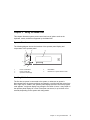
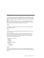
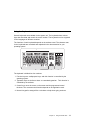
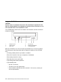
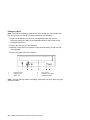
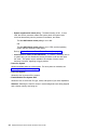
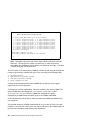
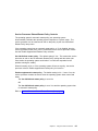
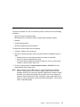
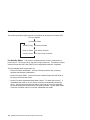
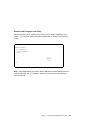
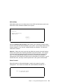
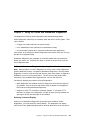
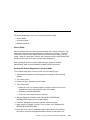
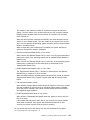
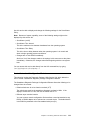
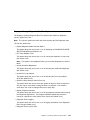
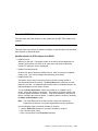
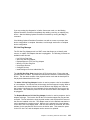
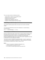
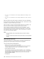
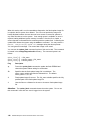
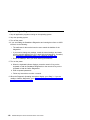
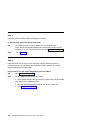
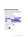
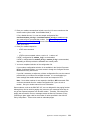
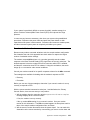
Operator Panel
The following diagram shows the locations of the operator panel display and
components of the operator panel.
6
R
5
1
2
3
3
2
1
4
Power On/Off Button
Power On/Off LED
Operator Panel Display
4
5
Reset Button
Disturbance or System Attention LED
Scrolling Ball Indicator
The first time ac power is connected to the system, or whenever ac power is
disconnected from the system and then reconnected, a scrolling ball that moves from
left to right may be visible in the operator panel display before the first 8xxx progress
code appears; it might not display long enough to be visible. If seen, it may remain in
the operator panel display for a time of less than one second, or up to three to five
seconds, depending on the system and configuration.
Chapter 2. Using the Model H80
3
Powering Off and Powering On the System
This section provides procedures for powering off and powering on the system.
Powering Off the System
If the system is operating under AIX, type the shutdown -F command to power off
the system.
If you cannot use this method, you can power off the system by using the following
operator-panel power button procedure.
Attention: Using the power button on the primary I/O drawer operator panel to power
off the system might cause unpredictable results in the data files, and the next IPL
will take longer to complete.
1. Open the rack door.
2. Press the power button on the primary I/O drawer operator panel.
The power LED on the primary I/O drawer operator panel starts blinking at a fast
rate. B0FF appears in the primary operator panel display.
When the power-off sequence is complete, the system goes into Standby mode, as
evidenced by the following:
OK message displays in the primary operator panel display.
The primary I/O drawer operator panel LED will start blinking at a slow rate.
The CEC drawer power LED will start blinking at a slow rate.
Powering On the System
Perform the following steps to power on the CEC drawer and attached I/O drawer:
1. Open the rack door. Look for OK in the primary operator panel display, which
indicates that the system is in Standby mode.
2. Press the power button on the primary I/O drawer operator panel.
The power LED on the primary I/O drawer operator panel starts blinking at a fast
rate. Checkpoints codes (9xxx) appear in the operator panel display.
When the power-up sequence is complete; the following events occur:
The power LED on the primary I/O drawer operator panel stops blinking and
stays on.
4
RS/6000 Enterprise Server Model H80 Series User's Guide
The power LED on the CEC drawer stops blinking and stays on.
Powering Off and Powering On the System Using the Service Processor
The system can be powered off and on using the System Power Control menu,
which is a Service Processor menu that is available to the privileged user. See
“System Power Control Menu” on page 39.
Chapter 2. Using the Model H80
5
POST Indicators
POST (Power-On-Self-Test) indicators indicate tests that are being performed as the
system is preparing to load the operating system. The POST indicators are words
that display on the system console. Each time that the system starts a different step
in the POST, a POST indicator word appears on the console. Each word is an
indicator of the tests that are being performed.
The POST screen displays the following words:
Memory
Memory test
Keyboard Initialize the keyboard and mouse. The time period for pressing a key to
access the System Management Services, or to boot from a default boot
list is now open. See “POST Keys” on page 7 for more information.
Network
Self-test on network adapters
SCSI
Adapters are being initialized
Speaker
Sounds an audible tone at the end of POST
6
RS/6000 Enterprise Server Model H80 Series User's Guide
POST Keys
The POST keys, if pressed after the keyboard POST indicator displays and before
the last POST indicator displays, cause the system to start services or boot modes
used for configuring the system and diagnosing problems. The keys are described
below:
Note: The program function keys (F1-F12) on a keyboard attached to the I/O
drawer are no longer used and will be ignored. After the keyboard POST indicator
displays, you must use the numeric number keys to enter input.
1 Key
The numeric 1 key, when pressed during POST, starts the System Management
Services (SMS) interface.
5 Key
The numeric 5 key, when pressed during POST, starts the default boot list mode,
located in firmware.
This mode attempts to boot from the first device of each type found in the list. It
does not search for other bootable devices of that type if the first device is not
bootable. Instead, it continues to the next device type in the list. The firmware
supports up to five entries in the boot list.
The default boot sequence is:
1.
2.
3.
4.
5.
Diskette
CD-ROM
Hard File
Tape Drive (if installed)
Network
a. Token Ring
b. Ethernet
6 Key
The numeric 6 key works like the numeric 5 key, except that firmware looks for a
boot record according to the custom bootlist that was set up by System Management
Services.
Chapter 2. Using the Model H80
7
8 Key
To enter the Open Firmware command line, press the numeric 8 key after the word
keyboard displays and before the last word (speaker) displays during startup. After
you press the 8 key, the remaining POST indicators display until initialization
completes.
When initialization and POST are complete, the Open Firmware command line (an OK
prompt) displays.
Use the Open Firmware command line to set up adapters that are not configurable
with the System Management Services. Your adapter documentation directs you to
use this option if it is needed.
To exit from the Open Firmware command prompt, type reset-all or power off the
system and reboot.
8
RS/6000 Enterprise Server Model H80 Series User's Guide
Console Strategy
The firmware starts a console-selection sequence at system boot time if any of the
following are true:
A console has not yet been selected
A previous console-selection sequence timed-out
A change in the system configuration has affected the console (keyboard
installed/removed, mouse installed/removed, graphics adapter installed/removed
or moved to another PCI slot).
The console-selection sequence allows you to select (from the appropriate input
device) any one of the available console devices. If no console is selected within
approximately 60 seconds, serial port 1 (S1) is selected as the console and the
selection sequence times-out.
Attention: If an ASCII terminal is attached to serial port 1 (S1), and there is any
interaction with this terminal:
After OK displays in the operator panel
AND
Before the power-up sequence is initiated
the firmware will still use this terminal as the console, regardless of the previous
console selection.
After a console has been selected, the console-selection sequence is only started at
boot time if there is a change in the system configuration (as described above), or
the contents of the system's nonvolatile memory (NVRAM) are lost.
Note: Moving an ASCII terminal from one serial port to another (from S1 to S2)
cannot be detected by the firmware, so it does not constitute a configuration change.
You can also initiate a system console-selection sequence from the SMS menus.
Chapter 2. Using the Model H80
9
Reading the I/O Drawer Operator Panel Display
The operator panel display is used to:
Track the progress of the system unit self tests and configuration program.
Display codes when the operating system comes to an abnormal end.
Display system messages.
Checkpoints
During power-on self-test (POST), four-digit checkpoints are displayed indicating the
progress of the testing. If an error is detected that requires attention, the system unit
halts with an eight-digit error code displayed in the upper row of the operator panel
display, starting in the leftmost position. This eight-digit error code identifies the error
(see RS/6000 Enterprise Server Model H80 Series Service Guide for a listing of the
error codes).
The four-digit checkpoints are in the form of nnnn, where n is an alphabetic or
numeric character.
10
RS/6000 Enterprise Server Model H80 Series User's Guide
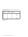
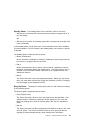
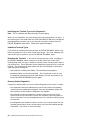
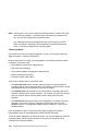
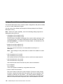
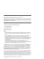
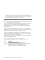
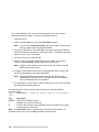
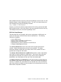
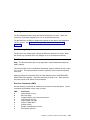
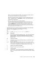
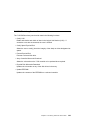
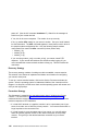
Using the Keyboards
Several keyboards are available for the system unit. The keyboards have various
keys that enter data and control the cursor location. The keyboards can be engraved
for the languages of different countries.
The functions of each keyboard depends on the software used. The character sets
for the keyboards are contained and explained in the documentation for your
operating system.
1
Esc
F1
F2
F3
F4
F5
F6
F7
F8
F9
F10
F11
F12
Print
Screen
Scroll
Lock
SysRq
@
!
1
Tab
#
3
2
Q
$
4
W
%
5
E
*
&
7
6
R
T
(
9
8
Y
U
_
-
)
0
I
O
+
=
Backspace
P
Insert
Delete
Pause
Num
Lock
Caps
Lock
Scroll
Lock
Break
Home
Page
Up
End
Page
Down
Num
Lock
/
*
7
8
9
Home
-
Pg Up
+
Caps
Lock
Shift
A
S
Z
D
X
F
C
G
V
H
B
J
N
K
M
L
<
,
:
;
"
,
?
/
>
.
Enter
Shift
4
5
1
2
End
6
3
Pg Dn
Enter
Ctrl
Alt
Alt
2
Ctrl
3
0
.
Ins
Del
4
The keyboard is divided into four sections:
1. Function keys are multipurpose keys, and their function is controlled by the
operating system.
2. Typewriter keys are similar to those on a standard typewriter. Their function is
controlled by the software.
3. Control keys move the cursor on the screen and do programmed control
functions. The movement and functions depend on the application used.
4. Numeric keypad is arranged like a calculator to help when typing numbers.
Chapter 2. Using the Model H80
11
All of the keyboards adjust for typing comfort. To tilt the keyboard, pull out the
keyboard legs. The legs snap into position. To decrease the tilt of the keyboard,
rotate the keyboard legs until they snap into the bottom of the keyboard case.
The keyboard cable plugs into the keyboard connector at the rear of the I/O drawer.
12
RS/6000 Enterprise Server Model H80 Series User's Guide
Using the Three-Button Mouse
The mouse is a hand-operated locating device. A three-button mouse is available for
use with the system unit. Consult your application publication for the exact use of
the three-button mouse.
You can use the mouse to perform such functions as positioning a cursor, selecting
items from a menu, or moving around in your document much easier and faster than
if you used only the keyboard. The cursor moves exactly as you move the mouse on
a flat surface, such as a desktop.
When you move the mouse around on a flat surface, the cursor moves on the
display screen; the movement changes the position of the cursor.
With the mouse buttons, you can perform functions such as selecting and
deselecting options, extending your selection, or choosing a command. The precise
function of your mouse depends on the software you are using.
The mouse has a cable that plugs into the mouse connector at the rear of the
primary I/O drawer.
Handling the Mouse Correctly
For best operation, handle the mouse with care. Incorrect handling can damage the
mouse.
Do not:
Operate the mouse on cloth, unfinished wood, newspaper, or carpet
Drop or hit the mouse
Carry the mouse by holding onto the cable
Expose the mouse to extreme temperatures or direct sunlight
Place the mouse in liquid spills
Chapter 2. Using the Model H80
13
Caring for the Mouse
Make sure that the operating surface for the mouse is smooth, clean, and flat. For
example, you can operate the mouse on the following surfaces:
Finished wood
Glass
Enamel
Plastic
Paper (except newspaper)
Metal
Rough surfaces collect contaminants that can be transferred to the interior of the
mouse by the ball. Rough surfaces can also cause the pads located on the bottom
of the mouse to prematurely wear. A deeply pitted surface could cause erratic
operation of the mouse. The surface you use should be free from spills, dirt, dust,
lint, wax, eraser dust, and other foreign matter.
Additional things to check:
Inspect the work surface for spills or other contaminants.
Dust the work surface.
If you are using a paper pad, inspect it for wear and replace it if necessary.
14
RS/6000 Enterprise Server Model H80 Series User's Guide
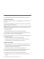
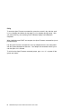
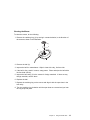
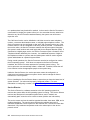
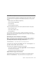
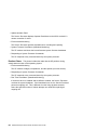
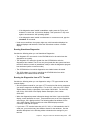
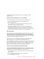
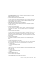
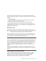
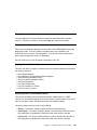
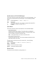
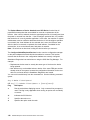
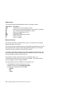
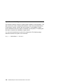
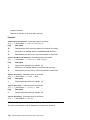
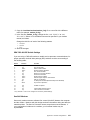
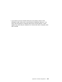
Cleaning the Mouse
To clean the mouse, do the following:
1. Remove the retaining ring (1) by turning it counterclockwise, in the direction of
the arrow as shown in the illustration.
1
2
3
2. Remove the ball (2).
3. Inspect the ball for contaminants. Wipe it clean with a dry, lint-free cloth.
4. If the ball is dirty, wash it in warm, soapy water. Rinse and wipe the ball with a
lint-free cloth until dry.
5. Inspect the ball cavity (3) in the mouse for foreign materials. If there are any
foreign materials, remove them.
6. Replace the ball.
7. Replace the retaining ring on the mouse and align it with the open slots in the
ball cavity.
8. Turn the retaining ring clockwise until the open slots are covered and you hear
the ring snap into place.
Chapter 2. Using the Model H80
15
Using the 3.5-Inch Diskette Drive
The Model H80 has a 1.44MB diskette drive installed vertically in the front.
The 1.44MB diskette drive can format, read, and write diskettes compatible with the
following diskettes:
1.0MB diskettes with 720KB formatted data capacity
2.0MB diskettes with 1.44MB formatted data capacity (HD)
Format the diskette according to its specified capacity.
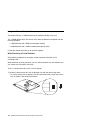
Write-Protecting 3.5-Inch Diskettes
Write-protecting diskettes is necessary so that important information is not
accidentally lost.
When diskettes are write-protected, you can read information from the diskettes, but
you cannot write information onto them.
There is a write-protect tab on the 3.5-inch diskette.
To locate the write-protect tab, turn the diskette over with the label facing down.
To prevent writing onto a diskette, slide the write-protect tab to open the protect
slot, as shown in the following illustration.
16
RS/6000 Enterprise Server Model H80 Series User's Guide
To allow writing onto a diskette, slide the write-protect tab to cover the protect
slot, as shown in the following illustration.
Loading and Unloading the 3.5-Inch Diskette
To load a diskette into the drive, insert the diskette in the diskette drive with the
labeled metal shutter first. Push the diskette into the drive until you hear a click.
The click indicates that the diskette is securely in position in the drive.
To unload the diskette, push the diskette-unload button. The diskette unloads
partially from the drive. Remove the diskette.
Chapter 2. Using the Model H80
17
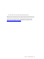
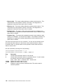
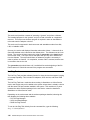
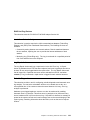
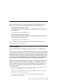
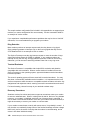
Using the CD-ROM Drive
CAUTION:
A Class 3 laser is contained in the device. Do not attempt to operate the drive
while it is disassembled. Do not attempt to open the covers of the drive, as it is
not serviceable and is to be replaced as a unit.
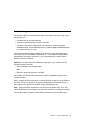
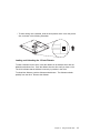
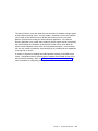
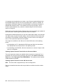
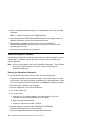
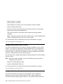
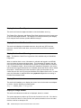
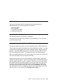
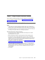
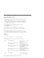
Your CD-ROM drive looks like the one shown in the illustration, and the controls are
located as indicated.
1
2
3
Headphone Jack
Volume Control
Status Light
4
5
6
Tray Opening
Emergency Eject Button
Load/Unload Button
When the CD-ROM is set to On, the status light indicates one of several conditions.
The following are status light states and the respective conditions of the CD-ROM
drive:
Off during standby with the tray loaded or unloaded
Blinks from insertion of the tray to completion of initialization
Blinks slowly when disc is dusty
Blinks fast when in the audio mode
Lights during data transfer operations
Lights steadily when:
– No disc is in the tray
– The disc is in the tray upside down
– Some condition exists that should be checked. If this occurs, contact your
service representative.
18
RS/6000 Enterprise Server Model H80 Series User's Guide
Loading the CD-ROM Drive
Press the unload button to open the tray. Place the disc, with the printed side away
from the tray, into the tray. Slip out the bottom tabs to hold the disc in place. Push
gently on the load/unload button. The drive automatically pulls the tray into the drive
and prepares the disc for reading.
Unloading the CD-ROM Drive
Push and hold the unload button until the drawer comes out, and then remove the
disc.
Cleaning the CD-ROM Drive
This CD-ROM drive has an internal head-cleaning mechanism, and therefore does
not require an external cleaning device. The internal cleaning mechanism cleans the
head every time the tray is operated.
Always handle discs carefully by the edges to avoid leaving fingerprints or scratching
the disc. This helps the disc to maintain good readability. Discs can be wiped with a
soft, lint-free cloth or lens tissue. Always wipe in a straight line from the inner hub to
the outer rim.
Chapter 2. Using the Model H80
19
Emergency Eject
Note: Execute the following procedure only in an emergency (such as when the
tray will not eject even though you have pressed the unload button).
1. Insert a small diameter rod, such as a straightened paper clip, into the
emergency eject hole. (Refer to the illustration below for the location of the
emergency eject hole.)
2. Push in the tool until you feel resistance.
3. Maintain a small amount of pressure on the rod while pulling on the tray with
your fingernail.
4. Pull the tray open and remove the disc.
1
2
3
Headphone Jack
Volume Control
Status Light
4
5
6
Tray Opening
Emergency Eject Button
Load/Unload Button
Note: Normally the tray makes a ratcheting sound when you pull it open using the
above procedure.
20
RS/6000 Enterprise Server Model H80 Series User's Guide
Ergonomic Information
After you have set up your system, we encourage you to visit the Healthy Computing
Web site. Good ergonomic practice is important to get the most from your
workstation and to avoid discomfort. This means that the equipment and the
workplace should be arranged to suit your individual needs and the kind of work you
do.
The Healthy Computing Web site gives ergonomic guidelines to help you understand
the ergonomic considerations that you should know when working at a computer
workstation. The address is:
http://www.us.pc.ibm.com/healthycomputing
Using the Service Processor and Service Director Features
The Service Processor and Service Director features protect users against
unnecessary system downtime by keeping support personnel (both internal and
external) aware of any unexpected changes in the system environment. In
combination, the two features provide a flexible solution to automated system
maintenance.
Service Processor
The Service Processor runs on its own power boundary and continually monitors
hardware attributes, the AIX operating system, and the environmental conditions
within the system. Any system failure which prevents the system from returning to
an operational state (a fully functional AIX operating system) is reported by the
Service Processor. The Service Processor is controlled by firmware and does not
require the AIX operating system to be operational to perform its tasks. If any
system failures are detected, the Service Processor can take predetermined
corrective actions. The methods of corrective actions are:
Surveillance
Call Home
AIX Operating System Monitoring
Surveillance is a function in which the Service Processor monitors the system
through heartbeat communication with the system firmware. The heartbeat is a
periodic signal that the firmware can monitor. During system startup, the firmware
surveillance monitor is automatically enabled to check for heartbeats from the
firmware. If a heartbeat is not detected within a default period, the Service
Processor attempts to reboot the system until the system either restarts successfully,
Chapter 2. Using the Model H80
21
or a predetermined retry threshold is reached. In the event the Service Processor is
unsuccessful in bringing the system online (or in the event that the user asked to be
alerted to any Service Processor-assisted restarts), the system can call home to
report the error.
The Call Home function can be initialized to call either a service center telephone
number, a customer administration center, or a digital pager telephone number. The
Service Processor can be configured to stop at the first successful call to any of the
numbers listed, or can be configured to call every number provided. If connected to
the service center, the Service Processor transmits the relevant system information
(the system's serial number and model type) and Service Request Number (SRN). If
connected to a digital pager service, the Service Processor inputs a Customer Voice
Telephone Number defined by the customer. An established sequence of digits or
the telephone number to a phone near the failed system could be used to signal a
system administrator to a potential system failure.
During normal operations, the Service Processor can also be configured to monitor
the AIX operating system. If AIX does not respond to the Service Processor
heartbeat, the Service Processor assumes the operating system is hung. The
service processor can automatically initiate a restart and, if enabled, initiate the call
home function to alert the appropriate people to the system hang.
Unlike the Service Director, the service processor cannot be configured in a
client/server environment where one system can be used to manage all dial-out
functions for a set of systems.
Prior to installing the Service Director feature, ensure that you have the latest level of
system firmware. You also need a properly configured modem. For more
information on configuring a modem, see “Modem Configuration Menu” on page 54.
Service Director
The Service Director is a software extension to the AIX operating system that
monitors the system while the AIX operating system is running. The Service Director
monitors and analyzes all recoverable system failures, and, if needed, can
automatically place a service call to a service center (without user intervention).
The service center receives the machine type/serial number, host name, SRN, and a
problem description. The service center analyzes the problem report and, if
warranted, dispatches a service person to the customer site. The service center also
determines if any hardware components need to be ordered prior to the service
person's arrival.
22
RS/6000 Enterprise Server Model H80 Series User's Guide
The Service Director code also gives the user the option to establish a single system
as the problem reporting server. A single system, accessible over the user network,
can be used as the central server for all the other systems on the Local Area
Network (LAN) that are running the Service Director application. If the Service
Director application on a remote client decides a service request needs to be placed,
the client forwards the information to the Service Director server which dials the
service center telephone number from its locally attached modem. In this scenario,
the user only needs to maintain a single analog line for providing call-out capabilities
for a large set of servers.
A modem is required for enabling automated problem reporting to the IBM service
center. Configuration files for several types of modems are included as part of the
Service Director package. Refer to “Modem Configuration Menu” on page 54 for
more information on configuring your modem.
Chapter 2. Using the Model H80
23
24
RS/6000 Enterprise Server Model H80 Series User's Guide
Chapter 3. Using the Service Processor
The service processor menus make it possible for you to configure service processor
options, as well as enable and disable functions.
Service processor menus are available using an ASCII terminal when OK is displayed
on the primary I/O drawer operator panel or when the service processor has
detected a server problem (such as a surveillance failure).
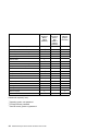
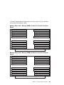
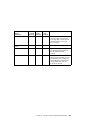
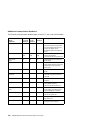
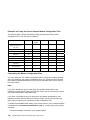
For a summary of the service processor functions and the methods used to invoke
them, see the following table.
Chapter 3. Using the Service Processor
25
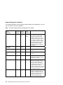
Service Processor Functions
Service
Processor
Menus
(ASCII
terminals)
Read VPD image from last system boot
Y3
Read System POST Errors
Y3
Read Service Processor Error Logs
Y3
View Progress Indicators from last boot
Y3
Power-off System
Y2
Read NVRAM
Y2
Start Talk Mode
Y2
Enable/Disable Console Mirroring
Y2
Setup Reboot/Restart Policy
Y2
Y1
Enable/Disable Modem
Y
2
Y1
Setup Modem Configuration
Y2
Y1
Setup Dial-out Phone Numbers
Y2
Y1
Setup Surveillance
Y
2
Y1
Select Modem Line Speed
Y2
Y1
Update System EPROMs
Y2
Y1
Change General Access Password
Y2
Change Privileged Access Password
Y2
Y2
2
Y2
Select Language
Y
Enable/Disable Unattended Start Mode
Y2
Passwords required (if set):
2
3
SMS
(ASCII or
graphics
terminals)
Y1
Save/Restore Hardware Maintenance Policies
1
Service
Processor
Service
Aids
(ASCII or
graphics
terminals)
Operating system root password
Privileged-access password
General access (power-on) password
26
RS/6000 Enterprise Server Model H80 Series User's Guide
Y1
Y2
Service Processor Menus
The service processor menus are divided into two groups:
General user menu - the user must know the general-access password.
Privileged user menus - the user must know the privileged-access password.
If the server is powered off, the service processor menus can be accessed locally or
remotely.
Accessing the Service Processor Menus Locally
Service processor menus can be accessed locally by connecting an ASCII terminal
to serial port 1 (S1), serial port 2 (S2), or serial port 3 (S3). Access to the service
processor menus is not available on serial port 4 (S4). Because the presence of the
ASCII terminal cannot be confirmed by the service processor, you must press a key
(any key) on the ASCII keyboard to confirm its presence after OK appears in the
primary drawer operator panel display.
When you gain access, the service processor prompts you for a password (if set),
and when verified, displays the service processor menus.
The service processor menu prompt, represented by ð>, 1> or 2> indicates the serial
port to which the terminal is connected.
ð> indicates serial port 1 (S1)
1> indicates serial port 2 (S2)
2> indicates serial port 3 (S3)
Accessing the Service Processor Menus Remotely
If your system has a modem connected and is configured for call-in (see “Modem
Configuration Menu” on page 54), the service processor menus can be accessed
remotely as follows:
1. With the system powered off, call in from a remote terminal.
2. The Service Processor detects ring-indicate and prompts you for a password (if
set). When verified, the service processor menus display remotely.
Saving and Restoring Service Processor Settings
All the settings you make (except language) from the service processor menus can
be backed up either for recovering from a fault that may corrupt these settings, or for
replicating these settings to other servers that include a service processor.
Chapter 3. Using the Service Processor
27
The service aid, Save or Restore Hardware Management Policies, can be used to
save your settings after initial setup or whenever the settings must be changed for
system operation purposes.
It is strongly recommended that you use this service aid for backing up service
processor settings to protect the usefulness of the service processor and the
availability of the server. Refer to “Save or Restore Hardware Management Policies”
on page 143 for information about this service aid.
Menu Inactivity
To prevent loss of control due to power loss or power surges, the service processor
attempts to leave menu mode after 10 minutes of inactivity by simulating the option
99 selection. This attempt is successful on menus containing the 99 option. On the
other menus, the attempt is unsuccessful and the following message displays with
each attempt:
Illegal value entered
Press Return to continue
28
RS/6000 Enterprise Server Model H80 Series User's Guide
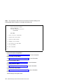
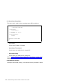
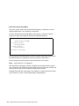
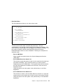
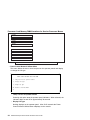
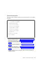
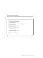
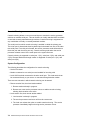
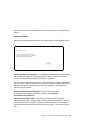
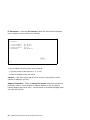
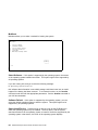
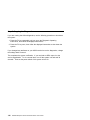
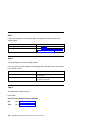
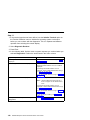
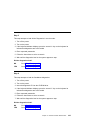
General User Menu
The menu options presented to the general user are a subset of the options
available to the privileged user. The user must know the general-access password,
if set, to access this menu.
à
ð
GENERAL USER MENU
1. Power-on System
2. Power-off System
3. Read VPD Image from Last System Boot
4. Read Progress Indicators from Last System Boot
5. Read Service Processor Error Logs
6. Read System POST Errors
99. Exit from Menus
1>
á
ñ
Power-on System
Allows the user to start up the system using the current ASCII terminal as the
active console.
Power-off System
Allows the user to power down the system using the current ASCII terminal as
the active console.
Read VPD Image from Last System Boot
Displays manufacturer vital product data, such as serial numbers, part numbers,
and so on, that were stored from the system boot prior to the one in progress
now.
Chapter 3. Using the Service Processor
29
Read Progress Indicators from Last System Boot
Displays a number of the boot progress indicators, which may include service
processor checkpoints, IPL checkpoints, and/or AIX configuration codes, from the
previous system boot. This information can be useful in diagnosing system faults.
The progress indicator codes are listed from top (latest) to bottom (oldest).
This information is not stored in nonvolatile storage. If the system is powered
down using the power-on button on the operator panel, this information is
retained. If the ac power is disconnected from the system, this information will be
lost. For an example, refer to “LCD Progress Indicator Log” on page 77.
Read Service Processor Error Logs
Displays the service processor error logs. For an example, refer to “Service
Processor Error Logs” on page 75.
Read System POST Errors
Displays the results of the System Firmware POST (Power-On Self Test). Your
server may be able to start in the presence of POST errors if there are sufficient
working system resources. If POST errors occur during startup, this error log,
when used with the diagnostics, helps to isolate faults. For an example, refer to
“Service Processor Error Logs” on page 75.
Exit from Menus
Selecting this option will exit the service processor menus. You can re-enter the
menus by pressing any key on the console.
30
RS/6000 Enterprise Server Model H80 Series User's Guide
Privileged User Menus
The following menus are available to privileged users only. The user must know the
privileged access password, if set, to access these menus.
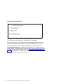
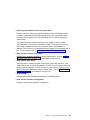
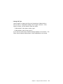
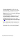
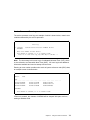
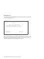
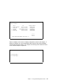
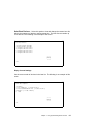
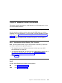
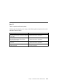
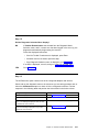
Main Menu
At the top of the Main Menu is a listing containing:
Your system's current firmware version
The firmware copyright notice
The system name given to your server during setup
You need the firmware version for reference when you either update or repair the
functions of your service processor.
The system name, an optional field, is the name that your server reports in problem
messages. This name helps your support team (for example, your system
administrator, network administrator, or service representative) to more quickly
identify the location, configuration, and history of your server. The system name is
set from the Main Menu using option 6.
Chapter 3. Using the Service Processor
31
Note: The information under the Service Processor Firmware heading in the
following Main Menu illustration is example information only.
à
ð
Service Processor Firmware
VERSION: MMððð313
Copyright 1999 IBM Corporation
SYSTEM NAME
MAIN MENU
1. Service Processor Setup Menu
2. System Power Control Menu
3. System Information Menu
4. Language Selection Menu
5. Call-In/Call-Out Setup Menu
6. Set System Name
99. Exit from Menus
1>
á
ñ
Service Processor Setup Menu
See “Service Processor Setup Menu” on page 33 for more information.
System Power Control Menu
See “System Power Control Menu” on page 39 for more information
System Information Menu
See “System Information Menu” on page 44 for more information.
Language Selection Menu
See “Language Selection Menu” on page 52 for more information.
Call-In/Call-Out Setup Menu
See “Call-In/Call-Out Setup Menu” on page 53 for more information.
Set System Name
Allows setting of the system name.
32
RS/6000 Enterprise Server Model H80 Series User's Guide
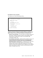
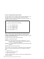
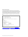
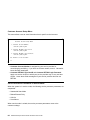
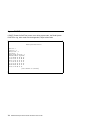
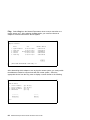
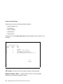
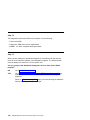
Service Processor Setup Menu
The Service Processor Setup menu shown below is accessed from the Main Menu:
à
ð
SERVICE PROCESSOR SETUP MENU
1. Change Privileged Access Password
2. Change General Access Password
3. Enable/Disable Console Mirroring:
Currently Enabled
4. Start Talk Mode
5. OS Surveillance Setup Menu
6. Reset Service Processor
7. Reprogram Flash EPROM Menu
8. Serial Port Snoop Setup Menu
98. Return to Previous Menu
99. Exit from Menus
1>
á
ñ
Note: Unless otherwise stated in menu responses, settings become effective when
a menu is exited using option 98 or 99.
Chapter 3. Using the Service Processor
33
Passwords
Passwords can be any combination of up to eight alphanumeric characters. You can
enter longer passwords, but the entries are truncated to include only the first eight
characters. The Privileged Access Password can be set from Service Processor
menus or from System Management Services (SMS) utilities (see Chapter 4, “Using
System Management Services” on page 81). The General Access Password can be
set only from Service Processor menus.
For security purposes, the service processor counts the number of attempts to enter
correct passwords. The results of not recognizing a correct password within this
error threshold are different, depending on whether the attempts are being made
locally (at the server) or remotely (through a modem). The error threshold is three
attempts.
If the error threshold is reached by someone entering passwords at the server, the
Service Processor commands the server to resume the initial program load (IPL).
This action is taken based on the assumption that the server is in an adequately
secure location with only authorized users having access. Such users must still
successfully enter a login password to access AIX.
If the error threshold is reached by someone entering passwords remotely, Service
Processor commands the server to power down to prevent potential security attacks
on the server by unauthorized remote users. The following table lists what you can
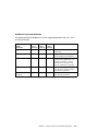
access with the Privileged Access Password and the General Access Password.
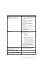
34
Privileged
Access
Password
General
Access
Password
Resulting Menu
None
None
Service processor MAIN MENU displays
Set
None
Users with the password see the service processor MAIN
MENU. Users without password cannot log in.
Set
Set
Users see menus associated with the entered password
RS/6000 Enterprise Server Model H80 Series User's Guide
Change Privileged Access Password
Set or change the Privileged Access Password. It provides the user with the
capability to access all service processor functions. This password is usually
used by the system administrator or root user.
Change General Access Password
Set or change the General Access Password. It provides limited access to
service processor menus, and is usually available to all users who are allowed to
power on the server, especially remotely.
Note: The General Access Password can only be set or changed after the
Privileged Access Password is set.
Enable/Disable Console Mirroring
Console mirroring is supported on serial port 1 (S1), serial port 2 (S2), and serial
port 3 (S3). When Console Mirroring is enabled, the service processor sends
information to all serial ports. The serial port from which console mirroring is
enabled is referred to as the active port. The mirror port is determined when
keyboard input is detected from one of the other ports. From this point on, the
service processor only sends information to the active port and the mirror port.
This capability can be enabled by local or remote users, providing local users
the capability to monitor remote sessions. Console mirroring can be enabled for
the current session only. For more information, see “Console Mirroring” on
page 74.
Start Talk Mode
In a console-mirroring session, it is useful for those who are monitoring the
session to be able to communicate with each other. Selecting this menu item
activates the keyboards and displays for such communications while console
mirroring is established. This is a full duplex link, so message interference is
possible. Alternating messages between users works best.
Chapter 3. Using the Service Processor
35
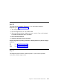
OS Surveillance Setup Menu
This menu can be used to set up operating system (OS) surveillance.
à
ð
OS Surveillance Setup Menu
1. Surveillance:
Currently Enabled
2. Surveillance Time Interval:
2 minutes
3. Surveillance Delay:
2 minutes
98. Return to Previous Menu
1>
á
ñ
– Surveillance
Can be set to Enabled or Disabled.
– Surveillance Time Interval
Can be set to any number from 2 through 255.
– Surveillance Delay
Can be set to any number from 0 through 255.
Refer to “Service Processor System Monitoring - Surveillance” on page 71 for
more information about surveillance.
Reset Service Processor
If this option is selected, entering Y will cause the service processor to reboot.
36
RS/6000 Enterprise Server Model H80 Series User's Guide
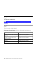
Reprogram Flash EPROM Menu
This option updates the system EPROMs. After entering Y to indicate that you
want to continue, you are prompted to enter the update diskettes. Follow the
instructions on the screen. When the update is complete, the service processor
reboots.
All system EPROMs that can be reprogrammed are updated at the same time.
They are as follows:
– System Power Control Network programming
– Service Processor programming
– IPL programming
– Run-Time Abstraction Services
Chapter 3. Using the Service Processor
37
Serial Port Snoop Setup Menu
This menu can be used to set up Serial Port Snooping, in which the user can
configure Serial Port 1 as a "catch-all" reset device.
From the Service Processor Main Menu, select option 1, Service Processor
setup menu, then select option 8 (Serial Port Snoop Setup Menu).
à
ð
SERIAL PORT SNOOP SETUP MENU
1. System reset string:
Currently Unassigned
2. Snoop Serial Port:
Currently Unassigned
98. Return to Previous Menu
1>
á
ñ
Use the system reset string option to enter the system reset string, which resets
the machine when it is detected on the main console on Serial Port 1.
Use the Snoop Serial Port option to select the Serial Port to Snoop.
Note:
Only Serial Port 1 is supported.
After Serial Port Snooping is correctly configured, at any point after the system
unit is booted to AIX, whenever the reset string is typed on the main console, the
system unit uses the Service Processor reboot policy to restart.
Pressing Enter after the reset string is not required, so make sure that the string
is not common or trivial. A mixed-case string is recommended.
38
RS/6000 Enterprise Server Model H80 Series User's Guide
System Power Control Menu
This menu is used to set power control options. Other menus that control boot
options are available here:
à
ð
SYSTEM POWER CONTROL MENU
1. Enable/Disable Unattended Start Mode:
Currently Enabled
2. Ring Indicate Power-On Menu
3. Reboot/Restart Policy Setup Menu
4. Power-On System
5. Power-Off System
6. Enable/Disable Fast System Boot
Currently Enabled
7. Boot Mode Menu
98. Return to Previous Menu
99. Exit from Menus
1>
á
ñ
Enable/Disable Unattended Start Mode
Use this option to instruct the service processor to restore the power-state of the
server after a temporary power failure. Unattended Start Mode can also be set
through the System Management Services (SMS) Menus. It is intended to be
used on servers that require automatic power-on after a power failure. For more
information, see “System Power-On Methods” on page 62.
Chapter 3. Using the Service Processor
39
Ring Indicate Power-On Menu
à
ð
RING INDICATE POWER-ON MENU
1. Ring indicate power-on :
Currently Enabled
2. Number of rings:
Currently 3
3ð. Refresh Modem Settings
98. Return to Previous Menu
á
ñ
Ring indicate is enabled by default on both serial port 1 (S1) and serial port 2
(S2). When ring indicate power on is enabled, call-in is disabled.
If ring indicate power-on is enabled and call-in is already enabled, you will be
asked to confirm your choice. Refer to the message displayed on your screen.
If the ring indicate power-on setting is changed, you must select option 30,
Refresh Modem Settings to update the modem settings. If option 30, Refresh
Modem Setting is selected, and the modem(s) have not been configured, you will
be asked to configure the modems first. See “Call-In/Call-Out Setup Menu” on
page 53 for information on configuring modems.
Option 2 is used to set the number of rings.
40
RS/6000 Enterprise Server Model H80 Series User's Guide
Reboot/Restart Policy Setup Menu
The following menu controls Reboot/Restart Policy:
à
ð
Reboot/Restart Policy Setup Menu
1. Number of reboot attempts:
Currently 1
2. Use OS-Defined restart policy?
Currently Yes
3. Enable supplemental restart policy?
Currently No
4. Call-Out before restart:
Currently Disabled
98. Return to Previous Menu
1>
á
ñ
Reboot is the process of bringing up the system hardware; for example, from a
system reset or power on. Restart is activating the operating system after the
system hardware is reinitialized. Restart must follow a successful reboot.
– Number of reboot attempts - If the server fails to successfully complete the
boot process, it attempts to reboot the number of times specified. Entry
values equal to or greater than 0 are valid. Only successive failed
reboot/restart attempts count.
– Use OS-Defined restart policy - Allows the service processor to react or not
react in the same way as the operating system to major system faults by
reading the setting of the operating system parameter Automatically
Restart/Reboot After a System Crash. This parameter may or may not be
defined, depending on the operating system or its version/level. If the
operating system automatic restart setting is defined, then it can be set to
respond to a major fault by restarting or by not restarting. See your operating
system documentation for details on setting up operating system automatic
restarts. The default value is YES.
Chapter 3. Using the Service Processor
41
– Enable supplemental restart policy - The default setting is NO. If set to
YES, the service processor restarts the system when the system loses
control as detected by service processor surveillance, and either:
The Use OS-Defined restart policy is set to NO.
OR
The Use OS-Defined restart policy is set to YES, and the operating
system has NO automatic restart policy.
Refer to “Service Processor Reboot/Restart Recovery” on page 64.
– Call-Out before restart (Enabled/Disabled) - If a restart is necessary due to
a system fault, you can enable the service processor to call out and report
the event. This option can be valuable if the number of these events
becomes excessive, signalling a bigger problem.
Power-On System
Allows immediate power-on of the system. For other power-on methods, see
“Powering On the System” on page 4.
Power-Off System
Allows the user to power-off the system.
Enable/Disable Fast System Boot
Allows the user to select the IPL type, mode, and speed of your boot capabilities.
Attention: Selecting the fast IPL results in several diagnostic tests being skipped
and a shorter memory test being run.
42
RS/6000 Enterprise Server Model H80 Series User's Guide
Boot Mode Menu
The Boot Mode Menu allows you to select a boot mode.
à
ð
Boot Mode Menu
1. Boot to SMS Menu:
Currently Disabled
2. Service Mode Boot from Saved List:
Currently Disabled
3. Service Mode Boot from Default List:
Currently Disabled
4. Boot to Open Firmware Prompt:
Currently Disabled
98. Return to Previous Menu
1>
á
ñ
To select a boot mode, select a number and press Enter. The item
corresponding to the selected number toggles from Disabled to Enabled. If the
same number is selected again, the item toggles from Enabled to Disabled. If a
boot mode is Enabled, the Boot mode selected is performed, and the
Disabled/Enabled selection is reset to Disabled. Following is a description for
each boot mode:
– Boot to SMS Menu
When enabled, the system boots to the System Management Services
(SMS) Menu.
– Service Mode Boot from Saved List
This selection causes the system to boot from the saved service mode boot
list (saved in NVRAM). This is normally used to try to boot Customer
Diagnostics from the CD-ROM drive. If the system boots AIX from the disk
drive and AIX diagnostics are loaded on the disk drive, AIX boots to the
diagnostics menu.
Using this option to boot the system is the preferred way to run Online
diagnostics.
– Service Mode Boot from Default List
This selection is similar to “Service Mode Boot from Saved List,” except the
system boots from the default boot list that is stored in the system firmware.
Using this option to boot the system is the preferred way to run Standalone
diagnostics.
Chapter 3. Using the Service Processor
43
– Boot to Open Firmware
When this selection is enabled, the system boots to the Open Firmware
prompt.
System Information Menu
This menu provides access to system configuration information, error logs, system
resources, and processor configuration.
à
ð
SYSTEM INFORMATION MENU
1. Read VPD Image from Last System Boot
2. Read Progress Indicators from Last System Boot
3. Read Service Processor Error Logs
4. Read System POST Errors
5. Read NVRAM
6. Read Service Processor Configuration
7. Processor Configuration/Deconfiguration Menu
8. Memory Configuration/Deconfiguration Menu
9. Power Control Network Utilities Menu
98. Return to Previous Menu
99. Exit from Menus
1>
á
ñ
Read VPD Image from Last System Boot
Displays manufacturer's vital product data (VPD), such as serial numbers, part
numbers, and so on, that was stored from the system boot prior to the one in
progress now.
44
RS/6000 Enterprise Server Model H80 Series User's Guide
Read Progress Indicators from Last System Boot
Displays a number of the boot progress indicators, which may include Service
Processor checkpoints, IPLROS checkpoints, and/or AIX configuration codes,
from the previous system boot. This information can be useful in diagnosing
system faults.
The progress indicator codes are listed from top (latest) to bottom (oldest).
This information is not stored in nonvolatile storage. If the system is powered
down using the power-on button on the operator panel, this information is
retained. If the ac power is disconnected from the system, this information will be
lost. For an example, refer to “LCD Progress Indicator Log” on page 77.
Read Service Processor Error Logs
Displays error conditions detected by the service processor. Refer to “Service
Processor Error Logs” on page 75 for an example of this error log.
Read System POST Errors
Select this item to review the results of the POST (Power-On Self Test). Your
server may be able to start in the presence of POST errors if there are sufficient
working system resources. If POST errors occur during startup, this error log,
when used with the diagnostics, helps to isolate faults. Refer to “System POST
Errors” on page 76 for an example of this error log.
Read NVRAM
Displays Non Volatile Random Access Memory (NVRAM) content.
Read Service Processor Configuration
Displays current service processor configuration.
Chapter 3. Using the Service Processor
45
Processor Configuration/Deconfiguration Menu
This menu allows the user to change the system processor configuration. If it is
necessary to take one of the processors offline, this menu allows you to
deconfigure a processor, and then reconfigure the processor at a later time. An
example of this menu is shown below:
à
ð
PROCESSOR CONFIGURATION/DECONFIGURATION MENU
77. Enable/Disable CPU Repeat Gard: Currently Enabled
1. ð 3.ð (ðð) Configured by system
2. 1 3.1 (31) Deconfigured by system
3. 2 3.2 (ðð) Configured by system
4. 3 3.3 (ðð) Configured by system
5. 4 4.ð (ðð) Configured by system
6. 5 4.1 (ðð) Configured by system
7. 6 4.2 (ðð) Configured by system
8. 7 4.3 (ðð) Configured by system
98. Return to Previous Menu
1>
á
ñ
Note: This table is built from vital product data collected during the last boot
sequence. The first time the system is powered up, or after the system's
non-volatile ram (NVRAM) has been erased, this table may be empty. The table
is rebuilt during the next boot into AIX.
The fields of the previous table represent the following:
Column 1 (1.) Menu selection index.
Column 2 (0) Logical processor device number assigned by AIX. You can
display these logical device numbers by issuing the command lsdev
-C ] grep proc on the AIX command line.
Column 3 (3.0) Processor address list used by the service processor and should
be ignored.
Column 4 (00) Error status of the processors.
The error status of the each processor is indicated by AB, where B indicates the
number of errors and A indicates the type of error according to the following
table:
1:
2:
3:
4:
Bring-up failure
Run-time non-recoverable failure
Run-time recoverable failure
Group integrity failure
A status of 00 indicates that the CPU has not had any errors logged against it by
the service processor.
46
RS/6000 Enterprise Server Model H80 Series User's Guide
To enable or disable CPU Repeat Gard, use menu option 77 of the Processor
Configuration/Deconfiguration Menu.
Note: The processor numbering scheme used by the Service Processor is
different from the numbering scheme used by AIX. Consult the AIX
documentation before configuring or deconfiguring a processor to ensure that the
correct processor is selected.
Memory Configuration/Deconfiguration Menu
These menus allow the user to change the system memory configuration. If it is
necessary to take one of the memory DIMMs offline, this menu allows you to
deconfigure a DIMM, and then reconfigure the DIMM at a later time.
When this option is selected, a menu displays, showing the memory riser cards
in the system. Type the number of the memory riser card on which the DIMM is
plugged that you want to configure or deconfigure. An example of this menu is
shown below:
à
ð
MEMORY CONFIGURATION/DECONFIGURATION MENU
77. Enable/Disable Memory Repeat Gard: Currently Enabled
1. Memory riser card 1
2. Memory riser card 2
98. Return to Previous Menu
á
ñ
Note: If there is only one processor in the system, system memory may reside
on that processor assembly. In that case, you are given the option to select the
processor card from the list. After you select a processor card or a memory riser
card, a menu allowing the selection of a memory DIMM is displayed. An
example of this menu is shown below:
Chapter 3. Using the Service Processor
47
à
ð
MEMORY CONFIGURATION/DECONFIGURATION MENU
77. Enable/Disable Memory Repeat Gard: Currently Enabled
1.
3.
5.
7.
9.
11.
13.
15.
98.
11.16(ðð) Configured by
11.18(ðð) Configured by
11.2ð(ðð) Configured by
11.22(ðð) Configured by
11.24(ðð) Configured by
11.26(ðð) Configured by
11.28(ðð) Configured by
11.3ð(ðð) Configured by
Return to Previous Menu
system
system
system
system
system
system
system
system
2.
4.
6.
8.
1ð.
12.
14.
16.
11.17(ðð)
11.19(ðð)
11.21(ðð)
11.23(ðð)
11.25(ðð)
11.27(ðð)
11.29(ðð)
11.31(ðð)
Configured
Configured
Configured
Configured
Configured
Configured
Configured
Configured
by
by
by
by
by
by
by
by
system
system
system
system
system
system
system
system
Memory DIMMs are managed as a group.
Deconfiguring a DIMM will make the whole group unavailable.
ð>
á
ñ
Note: This table is built from vital product data collected during the last boot
sequence. The first time the system is powered up, or after the system's
non-volatile ram (NVRAM) has been erased, this table may be empty. The table
is rebuilt during the next boot into AIX.
The error status of the each memory DIMM is indicated by AB, where B indicates the
number of errors and A indicates the type of error according to the following table:
1:
2:
3:
4:
Bring-up failure
Run-time non-recoverable failure
Run-time recoverable failure
Group integrity failure
A status of 00 indicates that the memory DIMM has not had any errors logged
against it by the service processor.
To change the memory configuration, select the number of the memory DIMM. The
memory DIMM state will change from configured to deconfigured or from
deconfigured to configured. Memory DIMMs are managed as a group;
deconfiguring a DIMM makes the whole group of four DIMMs unavailable.
In the example menu shown above, each line shows two DIMMs and whether they
are configured.
The physical location of a DIMM is determined by xx.yy, where xx is the riser card
location (11 for riser card 1 and 10 for riser card 2) followed by the DIMM location on
the riser card, according to the following two illustrations.
48
RS/6000 Enterprise Server Model H80 Series User's Guide
To enable or disable Memory Repeat Gard, use menu option 77 of the Processor
Configuration/Deconfiguration Menu.
Memory Riser Card 1 Memory DIMM Locations for Service Processor
Menus
15: 11.16
16: 11.18
13: 11.20
14: 11.22
11: 11.24
12: 11.26
9: 11.28
10: 11.30
7: 11.29
8: 11.31
5: 11.25
6: 11.27
3: 11.21
4: 11.23
1: 11.17
2: 11.19
Memory Riser Card 2 Memory DIMM Locations for Service Processor
Menus
15: 10.32
16: 10.34
13: 10.36
14: 10.38
11: 10.40
12: 10.42
9: 10.44
10: 10.46
7: 10.45
8: 10.47
5: 10.41
6: 10.43
3: 10.37
4: 10.39
1: 10.33
2: 10.35
Chapter 3. Using the Service Processor
49
Processor Card Memory DIMM Locations for Service Processor Menus
8: 3.48
7: 3.50
6: 3.52
5: 3.54
4: 3.55
3: 3.53
2: 3.51
1: 3.49
Power Control Network Utilities Menu
This menu allows the user to do a lamp test on the operator panels and display
or change the I/O type.
à
ð
POWER CONTROL NETWORK UTILITIES MENU
1. Lamp Test for all Operator Panels
2. Display I/O Type
3. Change I/O Type
98. Return to Previous Menu
1>
á
ñ
– Lamp Test for all Operator Panels
Selecting this option tests the operator panel indicators. When selected, the
indicators blink on and off for approximately 30 seconds.
– Display I/O Type
Nothing displays on the operator panel. After 20-30 seconds the Power
Control Network Utilities Menu redisplays on the console.
50
RS/6000 Enterprise Server Model H80 Series User's Guide
– Change I/O Type
Use this option to change the I/O type of the primary I/O drawer after a
service action or configuration change if the I/O type is incorrect. If this
option is chosen, you are asked to make two entries.
1. When asked for the drawer number, type 1.
2. When asked for the I/O type, type 85.
If you enter an invalid value, a failure message displays on the console. The
Power Control Network Utilities Menu is then redisplayed on the console.
Chapter 3. Using the Service Processor
51
Language Selection Menu
The service processor menus and messages are available in different languages.
This menu allows selecting languages in which the service processor and system
firmware menus and messages are displayed.
à
ð
LANGUAGE SELECTION MENU
1. English
2. Francais
3. Deutsch
4. Italiano
5. Espanol
6. Svenska
98. Return to Previous Menu
99. Exit from Menus
1>
á
ñ
Note: Your ASCII terminal must support the ISO-8859 character set to correctly
display languages other than English.
52
RS/6000 Enterprise Server Model H80 Series User's Guide
Call-In/Call-Out Setup Menu
This menu is used to configure a modem for the service processor to use to support
the system:
à
ð
CALL-IN/CALL-OUT SETUP MENU
1. Modem Configuration Menu
2. Serial Port Selection Menu
3. Serial Port Speed Setup Menu
4. Telephone Number Setup Menu
5. Call-Out Policy Setup Menu
6. Customer Account Setup Menu
7. Call-Out Test
98. Return to Previous Menu
99. Exit from Menus
1>
á
ñ
Modem Configuration Menu, see “Modem Configuration Menu” on page 54.
Serial Port Selection Menu, see “Serial Port Selection Menu” on page 55.
Serial Port Speed Setup Menu, see “Serial Port Speed Setup Menu” on
page 56.
Telephone Number Setup Menu, see “Telephone Number Setup Menu” on
page 57.
Call-Out Policy Setup Menu, see “Call-Out Policy Setup Menu” on page 59.
Customer Account Setup Menu, see “Customer Account Setup Menu” on
page 60.
Call-Out Test Menu tests the configuration after the modem is installed and
configured correctly.
Chapter 3. Using the Service Processor
53
Modem Configuration Menu
The first two lines of the Modem Configuration Menu are status lines showing the
current selections. Selections are made in the two sections labeled Modem Ports and
Modem Configuration File Name. Select the serial port that you want to activate and
then select the modem configuration file for the modem on the port. If you want to
set up all of the serial ports with modems, make your selections one port at a time.
Note: Modem configuration is only supported on serial port 1 (S1) and serial port 2
(S2).
à
ð
Modem Configuration Menu
Port 1 Modem Configuration File Name:
Port 2 Modem Configuration File Name:
To make changes, First select the port and then the configuration file
name
Modem Ports:
1. Serial port 1
2. Serial port 2
Modem
5.
6.
7.
8.
Configuration File Name:
none9. modem_z_sp
modem_f_sp
1ð. modem_m1_sp
modem_fð_sp
11. modem_mð_sp
modem_f1_sp
12. modem_m1_sp
3ð. Save configuration to NVRAM and Configure modem
98. Return to Previous Menu
ð>
á
ñ
For information on choosing a modem configuration file, see “Sample Modem
Configuration Files” on page 177, and “Transfer of a Modem Session” on page 183.
54
RS/6000 Enterprise Server Model H80 Series User's Guide
Serial Port Selection Menu
This menu allows you to enable and/or disable the call-in and call-out functions of
each serial port in any combination.
à
ð
Serial Port Selection Menu
1. Serial Port 1 Call-Out:
Currently Disabled
3. Serial Port 1 Call-In:
Currently Disabled
2. Serial Port 2 Call-Out:
Currently Disabled
4. Serial Port 2 Call-In:
Currently Disabled
98. Return to Previous Menu
á
ñ
Call-in and ring indicate power-on cannot be enabled at the same time. If ring
indicate power on is already enabled and you try to enable call-in, a message
prompts you for confirmation. Refer to the message displayed on the screen.
Chapter 3. Using the Service Processor
55
Serial Port Speed Setup Menu
This menu allows you to set serial port speed to enhance terminal performance or to
accommodate modem capabilities.
à
ð
Serial Port Speed Setup Menu
1. Serial Port 1 Speed:
Currently 96ðð
2. Serial Port 2 Speed:
Currently 96ðð
3. Serial Port 3 Speed:
Currently 96ðð
98. Return to Previous Menu
1>
á
ñ
A serial port speed of 9600 baud or higher is recommended. Valid serial port
speeds are shown below:
50
75
110
134
150
300
56
600
1200
1800
2000
2400
3600
RS/6000 Enterprise Server Model H80 Series User's Guide
4800
7200
9600
19200
38000
57600
115200
Telephone Number Setup Menu
Use this menu to set or change the telephone numbers for reporting a system failure.
à
ð
Telephone Number Setup Menu
1. Service Center Telephone Number:
Currently Unassigned
2. Customer Administration Center Telephone Number:
Currently Unassigned
3. Digital Pager Telephone Number:
Currently Unassigned
4. Customer Voice Telephone Number:
Currently Unassigned
5. Customer System Telephone Number:
Currently Unassigned
98. Return to Previous Menu
1>
á
ñ
Chapter 3. Using the Service Processor
57
Service Center Telephone Number is the number of the service center
computer. The service center usually includes a computer that takes calls from
servers with call-out capability. This computer is referred to as the "catcher."
The catcher expects messages in a specific format to which the service
processor conforms.
For more information about the format and catcher computers, refer to the
README file in the AIX /usr/samples/syscatch directory. Contact your service
provider for the correct service center telephone number to enter. Until you have
that number, leave this field unassigned.
Customer Administration Center Telephone Number is the number of the
System Administration Center computer (catcher) that receives problem calls
from servers. Contact your system administrator for the correct telephone
number to enter here. Until you have that number, leave this field unassigned.
Digital Pager Telephone Number is the number for a numeric pager carried by
someone who responds to problem calls from your server. Contact your
administration center representative for the correct telephone number to enter.
For test purposes, use a test number, which you can change later. See note on
page 73.
Customer Voice Telephone Number is the telephone number of a phone near
the server or answered by someone responsible for the server. This is the
telephone number left on the pager for callback. For test purposes, use a test
number, which you can change later.
Customer System Telephone Number is the telephone number to which your
server's modem is connected. The service or administration center
representatives need this number to make direct contact with your server for
problem investigation. This is also referred to as the call-in phone number.
58
RS/6000 Enterprise Server Model H80 Series User's Guide
Call-Out Policy Setup Menu
Callout settings can be set using the following menu:
à
ð
CALL-OUT POLICY SETUP MENU
1. Call-Out policy (First/All):
Currently First
2. Remote timeout, (in seconds):
Currently 12ð
3. Remote latency, (in seconds):
Currently 2
4. Number of retries:
Currently 2
98. Return to Previous Menu
1>
á
ñ
Call-Out policy can be set to first or all. If call-out policy is set to first, the
service processor stops at the first successful call-out to one of the following
numbers in the order listed:
1. Service Center
2. Customer Administrative Center
3. Pager
If call-out policy is set to all, the service processor attempts a call-out to all of
the following numbers in the order listed:
1. Service Center
2. Customer Administrative Center
3. Pager
Remote timeout and Remote latency are functions of your service provider's
catcher computer. Either use the defaults or contact your service provider for
recommended settings.
Number of retries is the number of times you want the server to retry calls that
failed to complete.
Chapter 3. Using the Service Processor
59
Customer Account Setup Menu
This menu allows users to enter information that is specific to their account.
à
ð
Customer Account Setup Menu
1. Customer Account Number:
Currently Unassigned
2. Customer RETAIN Login userid:
Currently Unassigned
3. Customer RETAIN login password:
Currently Unassigned
98. Return to Previous Menu
1>
á
ñ
Customer Account Number is assigned by your service provider for
record-keeping and billing. If you have an account number, enter it. Otherwise,
leave this field unassigned.
Customer RETAIN Login UserID and Customer RETAIN Login Password
apply to a service function to which your service provider may or may not have
access. Leave these fields unassigned if your service provider does not use
RETAIN.
Service Processor Procedures in Service Mode
When the system is in service mode, the following service-processor parameters are
suspended:
Unattended Start Mode
Reboot/Restart Policy
Call-Out
Surveillance.
When service mode is exited, the service processor parameters revert to the
customer settings.
60
RS/6000 Enterprise Server Model H80 Series User's Guide
Service Processor Functions
This section discusses some of the service processor functions in greater detail. The
service processor supports the functions listed in the following table.
Built-in Functions
Initialization and Test
Service Processor BIST
System Chip Initialization
BIST/POST errors and status
Isolation to Field Replaceable
Unit (FRU) on failure
CPU Complex validation
VPD Collection
Reset and Reboot on System
Firmware failure
Reboot on system failure
Error Data Collection
Configuration
System Management
Local User Function
User Interface
Power and Miscellaneous
Status and Data Access
Service Processor Setup
Utilities
Remote User Functions
Call-Out (Call Home)
Reporting
Call-In
Local async console
Text based menus with NLS
Operator Panel messages
Power On/Off
Configurable Reboot Policy
VPD
Error data (SP)
Error data (system)
Passwords
Phone numbers
Language (NLS) selection
Call-In/Call-Out enable/disable
System Name
Modem Configuration
OS termination
Boot failure
Surveillance failure
Checkstop
Machine check
Identify system by name
Power-on through ring-indicate
Password/security check
Console mirroring
Chapter 3. Using the Service Processor
61
System Power-On Methods
This section discusses the following system power-on methods:
Power-on Switch
Service Processor Menus
Privileged users can power-on the system by selecting the System Control
Power Menu option from the main menu and then selecting the Power-on
System option from the system power control menu. General users should select
Power-on System on the general user menu.
Remote Power-on via Ring-Indicate Signal
The server automatically powers on when it detects a "ring indicate" signal from
a modem attached to serial port 1 (S1) or serial port 2 (S2).
A remote user can call the server to activate ring detection by the modem.
Listen for a few more rings than the threshold number for starting the system.
The system powers on without answering the call.
Unattended start mode - refer to Enable/Disable Unattended Start Mode on
page 39.
The Service Processor can be enabled to recover from the loss of ac power (see
Enable/Disable Unattended Power-On Mode in the SYSTEM POWER CONTROL
MENU). When ac power is restored, the system returns to the then current
power state at the time ac loss occurred. For example, if the system was
powered-on when ac loss occurred, it reboots/restarts when power is restored. If
the system was powered-off when ac loss occurred, it remains off when power is
restored.
62
RS/6000 Enterprise Server Model H80 Series User's Guide
Timed power-on - refer to the shutdown -t command on servers using AIX.
Working in conjunction with AIX, the Service Processor in your server can
operate a timer, much like the wake-up timer on your clock radio. You can set
the timer so that your server powers on at a certain time after shutting down.
The timer is battery-operated, so power interruptions that occur while the server
is off do not affect its accuracy. Refer to the AIX shutdown -t command for
details on setting the timer.
Note: If an ac power loss is in progress when the Timed Power-On attempt
occurs, the server is not able to power on when ac power is restored.
Follow-up to a Failed Boot Attempt
The service processor initiates a power-on sequence if a failed boot attempt is
detected (due to a hardware or software failure).
Fast/Slow Boot (IPL) Capabilities
Using the service processor menus, you can select the IPL type, mode, and
speed of your boot capabilities.
Attention: Selecting fast IPL results in several diagnostic tests being skipped
and a shorter memory test being run.
Chapter 3. Using the Service Processor
63
Service Processor Reboot/Restart Recovery
Reboot describes bringing the system hardware back up; for example, from a system
reset or power-on. The boot process ends when control passes to the operating
system process.
Restart describes activating the operating system after the system hardware is
reinitialized. Restart must follow a successful reboot.
Boot (IPL) Speed
When the server enters reboot recovery, slow IPL is automatically started, which
gives the POST an opportunity to locate and report any problems that may otherwise
be untested.
Failure During Boot Process
During the boot process, either initially after system power-on or upon reboot after a
system failure, the service processor monitors the boot progress. If progress stops,
the service processor can reinitiate the boot process (reboot) if enabled to do so.
The service processor can re-attempt this process according to the number of retries
selected in the Reboot/Restart Policy Setup Menu.
Failure During Normal System Operation
When the boot process completes and control transfers to the operating system
(OS), the service processor can monitor operating system activity (see the Set
Surveillance Parameters option in the SERVICE PROCESSOR SETUP MENU). If
OS activity stops due to a hardware- or software-induced failure, the service
processor can initiate a reboot/restart process based on the settings in the Service
Processor Reboot/Restart Policy Setup Menu and the OS automatic restart settings
(see the operating system documentation).
If you are using the AIX operating system, the menu item under SMIT for setting the
restart policy is Automatically Reboot After Crash (True/False). The default is False.
When the setting is True, and if the service processor parameter "Use OS-Defined
Restart Policy" is Yes (the default), Service Processor takes over for AIX to
reboot/restart after a hardware or surveillance failure.
64
RS/6000 Enterprise Server Model H80 Series User's Guide
Service Processor Reboot/Restart Policy Controls
The operating system's automatic restart policy (see operating system
documentation) indicates the operating system response to a system crash. The
service processor can be instructed to refer to that policy by the Use OS-Defined
Restart Policy setup menu.
If the operating system has no automatic restart policy, or if it is disabled, then the
service processor-restart policy can be controlled from the service processor menus.
Use the Enable Supplemental Restart Policy selection.
Use OS-Defined restart policy - The default setting is Yes. This causes the service
processor to refer to the OS Automatic Restart Policy setting and take action (the
same action the operating system would take if it could have responded to the
problem causing the restart).
When this setting is No, or if the operating system did not set a policy, the service
processor refers to Enable supplemental restart policy for its action.
Enable supplemental restart policy - The default setting is No. If set to Yes, the
service processor restarts the server when the operating system loses control and
either:
The Use OS-Defined restart policy is set to No.
OR
The Use OS-Defined restart policy is set to Yes and the operating system has
no automatic restart policy.
Refer to “Service Processor Reboot/Restart Recovery” on page 64.
Chapter 3. Using the Service Processor
65
The following table describes the relationship among the operating system and
service processor restart controls:
1
2
OS Automatic
reboot/restart
after crash setting
Service processor
to use OS-Defined
restart policy?
Service Processor
Enable
supplemental restart
policy?
None
None
None
None
False2
False2
False2
False2
True
True
True
True
No
No
Yes1
Yes1
No
No
Yes1
Yes1
No
No
Yes1
Yes1
No1
Yes
No1
Yes
No1
Yes
No1
Yes
No1
Yes
No1
Yes
Service processor default
AIX default
66
RS/6000 Enterprise Server Model H80 Series User's Guide
System response
Restarts
Restarts
Restarts
Restarts
Restarts
Restarts
System Firmware Updates
This section describes the methods of reprogramming the system firmware. All types
of firmware that can be reprogrammed are updated at the same time. They are as
follows:
System Power Control Network programming
Service Processor programming
IPL programming
Run-time Abstraction Services
Three user-initiated processes can be used to update the firmware in the system:
Service Processor menu
Service Aids (available in AIX)
AIX command line
A fourth method, called recovery mode, is initiated automatically by the service
processor if the service processor programming has been corrupted. This method is
described later in this section.
Determining the Level of Firmware on the System
Note: This information may be superseded by the information that is available on
the RS/6000 Support Web site shown below. Always check the Web site for the
latest images and instructions for checking the firmware level.
The Web address is: http://www.rs6ððð.ibm.com/support/micro
The firmware level is denoted by XXYYMMDD, where XX = model designation, YY =
year, MM = month, and DD = day of the release.
The firmware level is displayed in two places on the system:
On the AIX command line, enter lscfg -vp]grep ROM. The last line displayed is
the firmware level of the system.
At the top of the Service Processor main menu.
Update Diskette Images and Instructions
Update diskette images and instructions are available from the RS/6000 Support
Web site. The Web address is: http://www.rs6ððð.ibm.com/support/micro
Chapter 3. Using the Service Processor
67
It is strongly recommended that you create a set of firmware update diskettes from
the RS/6000 Support Web site as soon as possible after a system is installed. As
noted below, the diskette images can be downloaded to any personal computer or
RS/6000 with Internet access. This method is the only way to acquire a set of
firmware update diskettes; they cannot be created using the Service Processor
menus or using AIX.
Retain and store the latest firmware diskettes each time the firmware gets updated in
the event that the firmware gets corrupted and must be reloaded.
Download the detailed instructions, as well as the latest flash images, from this Web
site. Before doing a system firmware update, check the Web site for the latest code
and images. Do not attempt a firmware update if you are unsure of the image you
have, or of the procedure required for the update.
The images are available on the Web site in either DOS format or AIX (backup)
format:
If downloading to a PC, download the DOS image and follow the instructions.
The diskettes that are created will be in AIX (backup) format.
If downloading to an RS/6000, follow the instructions to create an image on disk
drives or on diskettes.
Updating System Firmware From the Service Processor Menus
The service processor menus are available while the system is powered off. As a
privileged user, from the service processor main menu, select Service Processor
Setup, then select Reprogram Flash EPROM Menu. The update process requests
update diskettes as needed.
Updating System Firmware from the AIX Service Aids
Note: This service aid is supported only in On-Line Diagnostics.
Refer to the detailed instructions that are provided on the Web site with the latest
image.
68
RS/6000 Enterprise Server Model H80 Series User's Guide
Updating System Firmware from the AIX Command Line
Refer to the detailed instructions that are provided on the Web site with the latest
image.
Note: The update process can take up to sixty minutes, and the system will always
reboot itself during the update process.
Recovery Mode
If the service processor detects that its programming has been corrupted when it is
powering up to standby mode, it will enter recovery mode. In recovery mode, it will
ask for the firmware update diskettes by putting eight-digit codes on the operator
panel.
The eight-digit codes are as follows:
Code
Action
A1FD 0000
System firmware has been corrupted and must be reflashed.
A1FD 0001
Insert update diskette 1.
A1FD 0002
Insert update diskette 2.
A1FD 0003
Insert update diskette 3.
Notes:
1. If the wrong diskette is inserted at any time, or if the diskette is left in the drive
after it has been read, B1FD ðð1F is displayed, indicating that the wrong diskette
is in the drive.
2. If B1FD ðð1A is displayed at any time during the process, the service processor
must be reset by removing and reconnecting ac power.
After the update process is complete, the service processor resets itself and goes
through a complete reboot.
Chapter 3. Using the Service Processor
69
Configuring and Deconfiguring Processors or Memory
All failures that crash the system with a machine check or check stop, even if
intermittent, are reported as a diagnostic callout for service repair. To prevent the
recurrence of intermittent problems and improve the availability of the system until a
scheduled maintenance window, processors and memory modules with a failure
history are marked "bad" to prevent their being configured on subsequent boots.
A processor or memory module is marked "bad" under the following circumstances:
A processor or memory module fails built-in self test (BIST) or power-on self test
(POST) testing during boot (as determined by the Service Processor).
A processor or memory module causes a machine check or check stop during
runtime, and the failure can be isolated specifically to that processor or memory
module (as determined by the processor runtime diagnostics in the Service
Processor).
A processor or memory module reaches a threshold of recovered failures that
results in a predictive callout (as determined by the processor runtime
diagnostics in the Service Processor).
During boot time, the Service Processor does not configure processors or memory
modules that are marked "bad," much in the same way that it would deconfigure
them for BIST/POST failures.
If a processor is deconfigured, the processor remains offline for subsequent reboots
until the faulty processor is replaced. The Repeat Gard function also provides the
users with the option of manually deconfiguring a processor, or re-enabling a
previously deconfigured processor. For information on how to configure or
deconfigure a processor, see the Processor Configuration/Deconfiguration Menu on
page 46.
You can enable or disable CPU Repeat Gard or Memory Repeat Gard using the
Processor Configuration/Deconfiguration Menu, which is a submenu under the
System Information Menu.
Run-Time CPU Deconfiguration (CPU Gard)
L1 instruction cache recoverable errors, L1 data cache correctable errors, and L2
cache correctable errors are monitored by the processor runtime diagnostics (PRD)
code running in the Service Processor. When a predefined error threshold is met, an
error log with warning severity and threshold exceeded status is returned to AIX. At
the same time, PRD marks the CPU for deconfiguration at the next boot. AIX will
70
RS/6000 Enterprise Server Model H80 Series User's Guide
attempt to migrate all resources associated with that processor to another processor
and then stop the defective processor.
Run-Time Memory Page Deconfiguration (Memory Gard)
Correctable errors in system memory are monitored and tracked. When a predefined
error threshold is met, an error log with warning severity is returned to AIX. A
memory page will be deallocated by AIX.
Service Processor System Monitoring - Surveillance
Surveillance is a function in which the service processor monitors the system, and
the system monitors the service processor. This monitoring is accomplished by
periodic samplings called heartbeats.
Surveillance is available during two phases:
System firmware bringup (automatic)
Operating system runtime (optional)
System Firmware Surveillance
System firmware surveillance is automatically enabled during system power-on. It
cannot be disabled by the user.
If the service processor detects no heartbeats during system IPL (for 7 minutes), it
cycles the system power to attempt a reboot. The maximum number of retries is set
from the service processor menus. If the fail condition persists, the service
processor leaves the machine powered on, logs an error, and displays menus to the
user. If Call-out is enabled, the service processor calls to report the failure and
displays the operating-system surveillance failure code on the operator panel.
Chapter 3. Using the Service Processor
71
Operating System Surveillance
Operating system surveillance provides the service processor with a means to detect
hang conditions, as well as hardware or software failures, while the operating system
is running. It also provides the operating system with a means to detect a service
processor failure caused by the lack of a return heartbeat.
Operating system surveillance is not enabled by default, allowing you to run
operating systems that do not support this service processor option.
You can also use Service Processor Menus and Service Processor Service Aids to
enable or disable operating system surveillance.
For operating system surveillance to work correctly, you must set three parameters:
Surveillance enable/disable
Surveillance interval
The maximum time the service processor should wait for a heartbeat from the
operating system before timeout.
Surveillance delay
The length of time to wait from the time the operating system is started to when
the first heartbeat is expected.
Surveillance does not take effect until the next time the operating system is started
after the parameters have been set.
If desired, you can initiate surveillance mode immediately from Service Aids. In
addition to the three options above, a fourth option allows you to select immediate
surveillance, and rebooting of the system is not necessarily required.
If operating system surveillance is enabled (and system firmware has passed control
to the operating system), and the service processor does not detect any heartbeats
from the operating system, the service processor assumes the system is hung and
takes action according to the reboot/restart policy settings. See “Service Processor
Reboot/Restart Recovery” on page 64.
If surveillance is selected from the service processor menus which are only available
at bootup, then surveillance is enabled by default as soon as the system boots.
From Service Aids, the selection is optional.
72
RS/6000 Enterprise Server Model H80 Series User's Guide
Call-Out (Call-Home)
The service processor can call out (Call-Home) when it detects one of the following
conditions:
System firmware surveillance failure
Operating system surveillance failure (if supported by operating system)
Restarts
Critical hardware failure
Abnormal operating system termination
To enable the call-out feature, do the following:
1. Connect a modem to any serial port.
2. Set up the following using the Service Processor Menus or Diagnostic Service
Aids:
Enable call-out for the serial port where the modem is connected.
Enter the modem configuration file name.
Set up site-specific parameters (phone numbers for call-out, call-out policy,
number of call-out retries, and so on).
3. To call out before restart, set Call-out before restart to ENABLED from the
Reboot/Restart Policy Setup menu.
Note: Some modems, such as IBM 7857-017, are not designed for the paging
function. Although they can be used for paging, they will return an error
message when they do not get the expected response from another modem.
Therefore, even though the paging was successful, the error message will
cause the Service Processor to retry, continuing to place pager calls for the
number of retries specified in the Call-Out Policy Setup Menu. These retries
result in redundant pages.
Chapter 3. Using the Service Processor
73
Console Mirroring
Console mirroring allows a user on one serial port to monitor the service processor
activities on another serial port. This can be done on locally attached ASCII terminals
or terminals remotely attached through modems. Console mirroring is supported on
any combination of locally or remotely attached monitors.
The serial port from which console mirroring is enabled is called the primary port.
The mirror port is determined when keyboard input is detected from one of the other
two serial ports. From this point forward, the service processor sends information to
the active port and the mirror port only. Console mirroring ends when the service
processor releases control of the serial ports to the system firmware.
Console mirroring is supported on serial port 1 (S1), serial port 2 (S2), and serial port
3 (S3). Remote attachment through modem is supported on serial port 1 (S1) and
serial port 2(S2).
System Configuration
The following describes the configuration for console mirroring:
Service Processor
Modem connected to one serial port and enabled for incoming calls
Local ASCII terminal connected to the other serial port. This local terminal can
be connected directly to your server or connected through another modem.
There are two scenarios in which console mirroring can be started:
Remote session first, then local session added:
1. Remote session already in progress.
2. Remote user uses service processor menus to enable console mirroring,
allowing both consoles to be active.
Local session first, then remote session added:
1. Local session is already in progress.
2. The service processor receives a call from the remote user.
3. The local user selects the option to enable console mirroring. The service
processor immediately begins mirroring service processor menus.
74
RS/6000 Enterprise Server Model H80 Series User's Guide
Service Processor Error Logs
The service processor error logs, an example of which is shown below, contain error
conditions detected by the service processor.
à
ð
Error Log
1. 11/3ð/99
B1ðð4999
19:41:56 Service Processor Firmware Failure
Enter error number for more details.
Press Return to continue, or 'x' to return to menu.
Press "C" to clear error log, any other key to continue.
>
á
ñ
Note: The time stamp in this error log is Coordinated Universal Time (CUT), which
is also referred to as Greenwich Mean Time (GMT). AIX error logs have additional
information available and can time stamp with local time.
Entering an error number provides nine words of system reference code (SRC) data;
an example screen is shown below.
à
ð
Detail:
6ðð5
SRC
- - - - - - - - - - - - - - - - - - - - - - - - - - - - - - - - - - word11:B1ðð4999
word12:ð11ððð5D
word13:ðððððððð
word14:ðððððððð
word15:ðððð1111
word16:ððððð ððð
word17:B1ðð4AAA
word18:ð114ðð5D
word19:A4F1E9ð9
B1ðð4999
Press Return to continue, or 'x' to return to menu.
á
ñ
If Return is pressed, the contents of NVRAM will be dumped 320 bytes at a time,
starting at address 0000.
Chapter 3. Using the Service Processor
75
System POST Errors
If POST (Power-On Self-Test) errors occur during system start, the Read System
POST Error log, when used with the diagnostics, helps isolate faults.
à
ð
Read System POST Errors
Version : 1
Severity : 2
Disposition : ð
Initiator : ð
Event being reported : ð
Extended Error Log Data:
c2 ðð 84 ð9 2ð ð9 ð6 ðð
19 97 ð9 ð3 ðð ðð 49 42
4d 2c 73 7ð ðð ðð ðð ðð
ðð ðð 2b að ðð 13 ðð ð1
ðð ðð ðð ðð ðð ðð ðð ðð
49 42 4d ðð 55 3ð 2e 31
2d 5ð 31 2d 58 31 ðð
(Press Return to Continue)
á
76
ñ
RS/6000 Enterprise Server Model H80 Series User's Guide
LCD Progress Indicator Log
The following is an example of the LCD progress indicator log. It shows the types of
entries that may appear in the log, and is for example purposes only.
The progress indicator codes are listed from top (latest) to bottom (oldest).
à
ð
LCD Progress Indicator Log
BoFF
ð539..17
ð538..17
ð539..17
ð538..17
ð539..17
ð581
ð538..17
ð539..12
ð538..12
ð539..
ð821..ð1-K1-ðð
ð539..
ð728..ð1-R1-ðð-ðð
ð539..
ð664..4ð-6ð-ðð-1,ð
ð539..
ð777..Uð.2-P1-I14/E1
ð539..
ð742..Uð.2-P1-I12/E1
ð539..
ð776..Uð.2-P1-I1ð/T1
E139
E1FB
E139
E183
Press Return to continue, or 'x' to return to menu.
EAA1..Uð.1-P1-I14
E172..Uð.1-P1
E172..Uð.1-P1-I14
E172..Uð.1-P1
94BB
91ð9
938ð
91ð8
91ð7
91ð6
91ð5
9118
91ð4
91ð3
91ð2
9ðFD
>
á
ñ
Chapter 3. Using the Service Processor
77
Service Processor Operational Phases
This section provides a high-level flow of the phases of the Service Processor (SP).
SP Power Applied
Pre-Standby Phase
Standby Phase SP Menus Available
Bring-Up Phase SMS Menus Available
Runtime Phase AIX Login Prompt Available
Pre-Standby Phase: This phase is entered when the server is connected to a
power source. The server may or may not be fully powered on. This phase is exited
when the Power-On Self-Tests (POSTs) and configurations tasks are completed.
The Pre-Standby phase components are:
Service Processor Initialization - Service Processor performs any necessary
hardware and software initializations.
Service Processor POST - Service Processor conducts Power-On Self-Tests on
its various work and code areas.
Service Processor Unattended Start Mode Checks - To assist fault recovery. If
unattended start mode is set, the Service Processor automatically reboots the
server. Service Processor does not wait for user input or power-on command,
but moves through the phase and into the Bring-Up Phase. Access SMS menus
or Service Processor menus to reset the unattended start mode.
78
RS/6000 Enterprise Server Model H80 Series User's Guide
Standby Phase: The standby phase can be reached in either of two ways:
With the server off and power connected (the normal path), recognized by OK in
the LCD display.
OR
With the server on after an operating system fault, recognized by an 8-digit code
in the LCD display.
In the Standby phase, the SP takes care of some automatic duties and is available
for menus operation. The SP remains in the standby phase until a power-on request
is detected.
The Standby phase components are as follows:
Modem Configuration
Service Processor configures the modem (if installed) so that incoming calls can
be received, or outgoing calls can be placed.
Dial In
Monitor incoming phone line to answer calls, prompt for a password, verify the
password, and remotely display the standby menu. The remote session can be
mirrored on the local ASCII console if the server is so equipped and the user
enables this function.
Menus
The Service Processor menus are password-protected. Before you can access
them, you need either General User (Power-On Password or POP) or Privileged
User (Privileged Access Password or PAP).
Bring-Up Phase: This phase is entered upon power-on, and exited upon loading
of the operating system.
The bring-up phase components are as follows:
Retry Request Check
The Service Processor checks to see if the previous boot attempt failed. If the
specified number of failures are detected, the SP displays an error code and
places an outgoing call to notify an external party if the user has enabled this
option.
Dial Out
The Service Processor can dial a preprogrammed telephone number in the event
of an IPL failure. The Service Processor issues an error report with the last
reported IPL status indicated and any other available error information.
Chapter 3. Using the Service Processor
79
Update Operator Panel
The Service Processor displays Operator Panel data on the ASCII terminal if a
remote connection is active.
Environmental Monitoring
The Service Processor provides expanded error recording and reporting.
System Firmware Surveillance (Heartbeat Monitoring)
The SP monitors and times the interval between system firmware heartbeats.
Responding to System Processor Commands
The SP responds to any command issued by the system processor.
Runtime Phase: This phase includes the tasks that the SP performs during
steady-state execution of the operating system.
Environmental Monitoring
The SP monitors voltages, temperatures, and fan speeds (on some servers).
Responding to System Processor Commands
The SP responds to any command issued by the system processor.
Run-Time Surveillance (Heartbeat Monitoring)
If the device driver is installed and surveillance enabled, the Service Processor
monitors the system heartbeat. If the heartbeat times out, the Service Processor
places an outgoing call. This is different from the bring-up phase scenario,
where the specified number of reboot attempts are made before placing an
outgoing call.
80
RS/6000 Enterprise Server Model H80 Series User's Guide
Chapter 4. Using System Management Services
Use the System Management Services menus to view information about your system
and to perform tasks such as setting a password, changing the boot list, and setting
the network parameters.
The text-based Open Firmware command line (OK prompt), which is available from
the System Management Services Utilities menu, allows you to configure certain
adapters.
To start the System Management Services, do the following:
1. Turn on or restart the system.
2. Watch for the banner screen to appear on the display. If an ASCII terminal is
being used, the banner screen will be lines of text in the form of (RS/6000
RS/6000 RS/6000 ....). If a color monitor is attached to a graphics adapter and a
keyboard is connected to the primary I/O drawer, the banner screen will be a
graphical logo.
3. After the banner screen is displayed, the POST indicator words, memory,
keyboard, network, scsi and speaker appear across the bottom of the screen.
Press the numeric 1 key after the word keyboard appears, and before the last
word speaker appears.
For more information on the POST indicator words, refer to “POST Indicators” on
page 6.
Note: The System Management Services can also be started using the Service
Processor Boot Mode Menu. See "Boot Mode Menu" on page 43.
Chapter 4. Using System Management Services
81
After the System Management Services starts, the following screen displays:
à
ð
Utilities
1
2
3
4
5
6
7
8
Password Utilities
Display Error Log
Remote Initial Program Load Setup
SCSI Utilities
Select Console
MultiBoot
Select Language
OK Prompt
.------.
|X=Exit|
------'
===>
á
82
ñ
RS/6000 Enterprise Server Model H80 Series User's Guide
Each option on the System Management Services Utilities menu is described in this
section.
Password Utilities
Entering this selection permits access to the options shown on the following screen:
à
ð
Password Utilities
1 Set Privileged Access-Password
2 Remove Privileged-Access Password
3 Unattended Start Mode <ON>
.------.
|X=Exit|
------'
===>
á
ñ
Set Privileged-Access Password: The privileged-access password protects against
the unauthorized starting of the system programs. When this option is selected,
another screen displays that allows the setting of a password.
You can set the password from either the Service Processor or System Management
Services menus. After the password is set, both the Service Processor and System
Management Services automatically use the same password. The password is
limited to eight characters.
Remove Privileged-Access Password: If you previously had set a
privileged-access password and want to remove it, select Remove
Privileged-Access Password.
Unattended Start Mode <ON>: This selection is used to enable or disable
Unattended Start Mode. Use this option to instruct the Service Processor to restore
the power-state of the server after a temporary power failure, which is necessary on
servers that require automatic power-on after a power failure. The default setting is
ON.
Chapter 4. Using System Management Services
83
Display Error Log
A screen similar to the following displays when you select this option. You can view
or clear your system error log.
à
ð
.--------------------------------------------------------.
|
Error Log
|
|
|
|
|
|
Date
Time
ErrorCode Location
|
| Entry 1. 99/ð6/3ð ð2:15:35 25a8ðð11
U1.1-P1.1/Q1
|
| Entry 2. 99/ð7/ð1 ð3:18:36 2ð3ððð26
U1.1-P1.1/Q1
|
--------------------------------------------------------'
.-----------------.
|C=Clear Error Log|
-----------------'
.-----------.
|X=Exit Log |
-----------'
á
ñ
Note: The time stamp in this error log is Coordinated Universal Time (CUT), which
is also referred to as Greenwich Mean Time (GMT). AIX error logs have more
information available and can time stamp with your local time.
84
RS/6000 Enterprise Server Model H80 Series User's Guide
Remote Initial Program Load Setup
This option allows you to enable and set up the remote startup capability of your
system. You must first specify the network parameters as shown in the following
screen:
à
ð
Network Parameters
1. IP Parameters
2. Adapter Parameters
3. Ping
.------.
|X=Exit|
------'
===>
á
ñ
Note: Some applications may require that IP addresses contain leading zeroes for
numbers less than 100. For example, 129.132.4.20 may need to be entered as
129.132.004.020.
Chapter 4. Using System Management Services
85
IP Parameters: Select the IP Parameters option from the Network Parameters
menu to display a screen similar to the following:
à
ð
IP Parameters
1.
2.
3.
4.
Client IP Address
Server IP Address
Gateway IP Address
Subnet Mask
[9.3.146.162]
[9.3.146.171]
[ð.ð.ð.ð]
[255.255.255.ð]
.------.
|X=Exit|
------'
===>
á
ñ
To set an address using this menu, do the following:
1. Type the number of the selection (1, 2, 3, or 4).
2. Enter the address on the next screen.
Attention: If the client system and the server are on the same subnet, set the
gateway IP address to [0.0.0.0].
Adapter Parameters: Select the Adapter Parameters option from the Network
Parameters menu to view an adapter's hardware address, as well as configure
network adapters that require setup. A screen similar to the following displays when
you make this selection:
86
RS/6000 Enterprise Server Model H80 Series User's Guide
à
ð
Adapter Parameters
Device
1.
2.
3.
4.
5.
Slot
Hardware Address
Gigabit Ethernet
4: Uð.1-P1-I4/E1
token-ring
5: Uð.1-P1-I5/T1
ethernet
Integrated:Uð.1-P1/E1
ethernet
2: Uð.2-P1-I2/E1
token-ring
3: Uð.2-P1-I3/T1
ððð4ac7cð135
ðð2ð357a91ð5
ðð6ð949d7ac5
ððð4ac5e692b
ððð4ac634e38
.------.
|X=Exit|
------'
(PRESS ENTER AFTER MAKING A SELECTION) ===>
á
ñ
Select an adapter on this screen to display configuration menus for that adapter. If
ethernet is selected, you can set parameters that control how the ethernet adapter
communicates with the network. For example, the following screen shows the menu
for the ethernet adapter configuration:
à
ð
1. Data Rate [Auto]
2. Full Duplex [No]
á
ñ
Chapter 4. Using System Management Services
87
Ping: Select Ping from the Network Parameters menu to test a connection to a
remote system unit. After selecting the Ping option, you must first choose an
adapter to communicate with the remote system.
à
ð
Adapter Parameters
Device
1.
2.
3.
4.
5.
Slot
Hardware Address
Gigabit Ethernet
4: Uð.1-P1-I4/E1
token-ring
5: Uð.1-P1-I5/T1
ethernet
Integrated:Uð.1-P1/E1
ethernet
2: Uð.2-P1-I2/E1
token-ring
3: Uð.2-P1-I3/T1
ððð4ac7cð135
ðð2ð357a91ð5
ðð6ð949d7ac5
ððð4ac5e692b
ððð4ac634e38
.------.
|X=Exit|
------'
(PRESS ENTER AFTER MAKING A SELECTION) ===>
á
ñ
After determining which adapter to use to ping the remote system, you must provide
the addresses needed to communicate with the remote system. Select the
appropriate device from the Ping menu to display a screen similar to the following:
à
ð
PING IP Address
1.
2.
3.
4.
Client IP Address
Server IP Address
Gateway IP Address
Subnet Mask
.---------.
|E=Execute|
---------'
[9.3.146.162]
[9.3.146.171]
[ð.ð.ð.ð]
[ð.ð.ð.ð]
.------.
|X=Exit|
------'
===>
á
88
ñ
RS/6000 Enterprise Server Model H80 Series User's Guide
SCSI Utilities
SCSI Utilities allow you to set delay times for the SCSI hard disk spin-up and to set
SCSI IDs for SCSI controllers installed in the system.
à
ð
SCSI Utilities
1. Harddrive Spin Up Delay
2. Change SCSI Id
.--------.
| X=Exit |
--------'
===>
á
ñ
Using the Harddrive Spin Up Delay option allows you to change the spin up delay
time for SCSI hard disk drives attached to your system. Spin up delay values can be
entered manually, or you can use a default setting (two seconds). All values are
measured in seconds.
Attention: Setting the value lower than the default can prevent successful booting
because the system power handling capabilities might be exceeded. If the system
no longer boots after setting this value, access this utility again and increase the
value. It is also possible that adding disk drives can cause similar symptoms.
Changing this value changes the surge current requirements on the system. As you
increase the value, the surge current requirements on the system are decreased.
Select Console
Select this option to define which display is used by the system for system
management. If no console is selected, the console defaults to Serial Port 1.
à
ð
Press ð to select this console
as the active console
á
ñ
Chapter 4. Using System Management Services
89
Multiboot
Multiboot allows you to select a method for booting the system.
à Multiboot
1
2
3
4
5
6
ð
Select Software
Software Default
Select Install Device
Select Boot Devices
OK Prompt
Multiboot Startup <OFF>
.------.
|X=Exit|
------'
===>
á
ñ
Select Software: If this option is supported by the operating system, the names
of the operating system installed are shown. This option might not be supported by
all operating systems.
If you are running AIX, and you receive the following message:
No Operating System Installed
this indicates that information in nonvolatile storage could have been lost, as would
happen if the battery had been removed. To re-create this value, run the bootlist
command under AIX with the appropriate parameters. See the bootlist command in
your AIX documentation.
Software Default: If this option is supported by the operating system, you can
select the default operating system to start the system. This option might not be
supported by all operating systems.
Select Install Device: Produces a list of devices, such as the CD-ROM, from
which the operating system may be installed. Select a device, and the system
searches that device for an operating system to install. If the device supported by the
operating system is that device, the name of the operating system displays.
90
RS/6000 Enterprise Server Model H80 Series User's Guide
Select Boot Devices: Select this option to view and change the custom boot list,
which is the sequence of devices read at startup time. The boot list can contain up
to five devices. The following is an example of this screen.
à Select Boot Devices
1
2
3
4
5
6
7
ð
Display Current Settings
Restore Default Settings
Configure 1st Boot Device
Configure 2nd Boot Device
Configure 3rd Boot Device
Configure 4th Boot Device
Configure 5th Boot Device
.------.
|X=Exit|
------'
====>
á
ñ
Display Current Settings
Lists the current order of devices in the boot list. The following is an example of this
screen.
à Current Boot Sequence
1.
2.
3.
4.
5.
ð
Diskette
SCSI CD-ROM id=1 ( loc=Uð.1-P1/Z1 )
SCSI 91ðð MB Harddisk id=5 ( loc=Uð.1-P1/Z1 )
Ethernet ( loc=Uð.1-I4/E1 )
None
.------.
|X=Exit|
------'
===>
á
ñ
Chapter 4. Using System Management Services
91
Restore Default Settings
Restores the boot list to the following default sequence:
Primary diskette drive
CD-ROM drive
Tape (if installed)
Hard disk drive
Network device
Selecting any of the Configure Boot Device options displays a screen similar to the
following.
à
ð
Configure Nth Boot Device
Device
Number
1
2
3
4
5
Current
Position
1
4
2
3
Device
Name
Diskette
Ethernet ( loc=Uð.1-P1-I4/E1 )
Token-Ring ( loc=Uð.1-P1-I5/T1 )
SCSI CD-ROM id=1 ( loc=Uð.1-P1/Z1 )
SCSI 91ðð MB Harddisk id=5 ( loc=Uð.1-P1/Z1 )
.------.
|X=Exit|
------'
===>
á
ñ
OK Prompt: Provides access to the Open Firmware command prompt.
Multiboot Startup <OFF>: Toggles between off and on to select whether
Multiboot menu starts automatically on startup.
92
RS/6000 Enterprise Server Model H80 Series User's Guide
Select Language
Select this option to change the language used by the System Management Services
screens and the Service Processor menus.
à
ð
Select Language
1.
2.
3.
4.
5.
6.
English
Francais
Deutsch
Italiano
Espanol
Svenska
===>
.------.
|X=Exit|
------'
á
ñ
Note: To correctly display languages other than English, your ASCII terminal must
support the ISO-8859 character set.
OK Prompt
This option provides access to the Open Firmware command prompt. Use the Open
Firmware command prompt to set up an adapter that is not configurable with the
System Management Services. Documentation supplied with an adapter may direct
you to use this option if it is needed. To exit from the Open Firmware command
prompt, type:
reset-all
or power off the system and reboot.
Exiting System Management Services
After you have finished using the System Management Services, type x (for exit) to
boot your system.
Chapter 4. Using System Management Services
93
94
RS/6000 Enterprise Server Model H80 Series User's Guide
Chapter 5. Using the Online and Standalone Diagnostics
The diagnostics consist of Online Diagnostics and Standalone diagnostics.
Online Diagnostics, when they are installed, reside with AIX in the file system. They
can be booted:
in single user mode (referred to as service mode)
run in maintenance mode (referred to as maintenance mode)
run concurrently (referred to as concurrent mode) with other applications.
If the system is not booted, the Online Diagnostics have access to the AIX error log
and the AIX configuration data.
Standalone Diagnostics are packaged on removable media and must be booted
before they can be run. If booted, they have no access to the AIX error log or the
AIX configuration data.
Online and Standalone Diagnostics Operating Considerations
Note: When possible, run Online Diagnostics in service mode. Online Diagnostics
perform additional functions, compared to Standalone Diagnostics. Running Online
Diagnostics in service mode ensures that the error state of the system is captured in
NVRAM for your use in fixing the problem. The AIX error log and certain SMIT
functions are only available when diagnostics are run from the disk drive.
Consider the following items before using the diagnostics:
When diagnostics are installed, the device support for some devices might not
get installed. If this is the case, that device does not appear in the diagnostic
test list when running disk-based diagnostics.
Support for some TTY terminals is optionally installed. If you attach a TTY
terminal to a system to run diagnostics, it might not work correctly because the
AIX support for the terminal might not be installed.
Selecting a Console Display
When you run Standalone Diagnostics (and under some conditions, Online
Diagnostics), you must select the console display. The diagnostics can display
instructions on any graphical display and the terminal attached to the S1 serial port.
Chapter 5. Using the Online and Standalone Diagnostics
95
Identifying the Terminal Type to the Diagnostics
Note: This is a different task than selecting a console display.
When you run diagnostics, you must identify which type of terminal you are using. If
the terminal type is not known when the FUNCTION SELECTION menu is displayed,
the diagnostics do not allow you to continue until a terminal is selected from the
DEFINE TERMINAL option menu. Select lft for graphical displays.
Undefined Terminal Types
If you specify an undefined terminal type from the DEFINE TERMINAL option menu,
the menu prompts the user to enter a valid terminal type. The menu redisplays until
either a valid type is entered or you exit the DEFINE TERMINAL option.
Resetting the Terminal: If you enter a terminal type that is valid (according to
the DEFINE TERMINAL option menu) but is not the correct type for the ASCII
terminal being used, you may be unable to read the screen, use the function keys, or
use the Enter key. These difficulties can be bypassed by pressing Ctrl-C to reset the
terminal. The screen display which results from this reset depends on the mode in
which the system is being run:
Online Normal or Maintenance Mode - The command prompt appears.
Standalone Mode or Online Service Mode - The terminal type is reset to dumb,
the Diagnostic Operating Instruction panel displays, and you are required to go
through the DEFINE TERMINAL process again.
Running Online Diagnostics
Consider the following when you run the Online Diagnostics from a server or a disk:
The diagnostics cannot be loaded and run from a disk until the AIX operating
system has been installed and configured. After the AIX operating system has
been installed, all three modes of diagnostics are available.
The diagnostics cannot be loaded on a system (client) from a server if that
system is not set up to boot from a server over a network. When the system is
set up to boot from a server, the diagnostics are run in the same manner as they
are from disk.
If the diagnostics are loaded from disk or a server, you must shut down the AIX
operating system before turning off the system unit to prevent possible damage
to disk data. This is done in one of two ways:
96
RS/6000 Enterprise Server Model H80 Series User's Guide
– If the diagnostics were loaded in standalone mode, press the F3 key until
DIAGNOSTIC OPERATING INSTRUCTIONS displays. Then press the F3 key once
again to shut down the AIX operating system.
– If the diagnostics were loaded in maintenance or concurrent mode, type the
shutdown -F command.
Under some conditions, the system might stop, with instructions displayed on
attached displays and terminals. Follow the instructions to select a console
display.
Running Standalone Diagnostics
Consider the following when you run Standalone Diagnostics:
The diagnostic CD must remain in the CD-ROM drive for the entire time that
diagnostics are running.
The diagnostic CD cannot be ejected from the CD-ROM drive after the
diagnostics have loaded. The CD can only be ejected after the system has been
turned off and then turned on (standalone mode) or after the diagnostics program
has terminated (online concurrent mode).
The CD-ROM drive from which diagnostics were loaded cannot be tested.
The SCSI adapter (or circuitry) controlling the CD-ROM drive from which
diagnostics were loaded cannot be tested.
Running the Diagnostics from a TTY Terminal
Consider the following when you run diagnostics using a TTY-type terminal as the
console display:
See the operator manual for your type of TTY terminal to find the key sequences
you need to respond to the diagnostics. For the 3151, refer to the 3151 ASCII
Display Station Guide to Operations, form number GA18-2633. For the 3164,
refer to the 3164 ASCII Color Display Station Description, form number
GA18-2617.
When the diagnostics present information through the Serial 1 port to the ASCII
display, certain attributes are used. These attributes are set as if the diagnostics
were using a 3161 display terminal. The following tables list attributes for the
3161 ASCII Display Terminal and for two other ASCII display terminals
commonly used with the system.
If you have a TTY terminal other than a 3151, 3161, or 3164 attached to the S1
serial port, your terminal may have different names for the attributes. Use the
attribute descriptions in the following tables to determine the settings for your
terminal.
Chapter 5. Using the Online and Standalone Diagnostics
97
Required Diagnostic Attributes
The following attributes are the required default settings for the diagnostics. Be sure
your terminal is set to these attributes.
Note: Set these attributes before the diagnostics are loaded.
General
Setup
Attributes
3151
/11/31/41
Settings
3151
/51/61
Settings
3161/
3164
Settings
Description
Machine mode
3151
3151
PC
3161
or
3164
The diagnostics are set to emulate
use of the 3161 ASCII Display
Terminal. If your terminal can
emulate a 5085, 3161, or 3164
terminal, use the attribute settings
in this table. Otherwise, refer to
your operator's manual, compare
the attribute setting descriptions in
this table with those of your
terminal, and set your attributes
accordingly.
Generated
Code Set
ASCII
Screen
Normal
Normal
Uses the EIA-232 interface
protocol.
Row
and
filemn
24 x 80
24 x 80
Uses the EIA-232 interface
protocol.
Scroll
Jump
Jump
Jump
When the last character on the
bottom line is entered, the screen
moves down one line.
Auto LF
Off
Off
Off
For the "On" setting, pressing the
Return key moves the cursor to
the first character position of the
next line. For the "Off" setting,
pressing the Return key moves the
cursor to the first character
position of the current line. The CR
and LF characters are generated
by the New line setting.
CRT saver
Off
Off
10
The "10" setting causes the display
screen to go blank if there is no
activity for 10 minutes. When the
system unit sends data or a key is
pressed, the display screen
contents are displayed again.
98
RS/6000 Enterprise Server Model H80 Series User's Guide
General
Setup
Attributes
3151
/11/31/41
Settings
3151
/51/61
Settings
3161/
3164
Settings
Description
Line wrap
On
On
On
The cursor moves to the first
character position of the next line
in the page after it reaches the last
character position of the current
line in the page.
Forcing
insert
Off
Off
Tab
Field
Field
Field
The column tab stops are ignored,
and the tab operation depends on
the field attribute character
positions.
All
Both inbound data and outbound
data to and from the main port can
be transferred to the auxiliary port
without disturbing communications
with the system unit when the
Trace key is pressed.
Trace
Chapter 5. Using the Online and Standalone Diagnostics
99
Additional Communication Attributes
The following communication attributes apply to the 3151, 3161, and 3164 terminals.
Communication
Setup
Attributes
3151
/11/31/41
Settings
3151
/51/61
Settings
3161/3164
Settings
Description
Operating mode
Echo
Echo
Echo
Data entered from the keyboard on
the terminal is sent to the system
unit for translation and then sent
back to the display screen.
Sometimes called conversational
mode.
Line speed
9600
bps
9600
bps
9600
bps
Uses the 9600 bps (bits per
second) line speed to
communicate with the system unit.
Word length
(bits)
8
8
8
Selects eight bits as a data word
length (byte).
Parity
No
No
No
Does not add a parity bit, and is
used together with the word length
attribute to form the 8-bit data
word (byte).
Stop bit
1
1
1
Places a bit after a data word
(byte).
Turnaround
character
CR
CR
CR
Selects the carriage return (CR)
character as the line turnaround
character.
Interface
EIA-232
EIA-232
EIA-232
Uses the EIA-232 interface
protocol.
Line control
IPRTS
IPRTS
IPRTS
Uses the Permanent Request to
Send (IPRTS) signal to
communicate with system unit.
Break signal
(ms)
500
500
500
The terminal sends a Break Signal
to the system unit within 500 ms
after the Break key is pressed.
Send null suppress
On
On
Send null
Response delay (ms)
100
100
100
Trailing null characters are not
sent to the system unit.
On
Trailing null characters are sent to
the system unit.
100
The terminal waits for 100ms for
the system unit to respond.
RS/6000 Enterprise Server Model H80 Series User's Guide
Additional Keyboard Attributes
The following keyboard attributes are for the keyboard attached to the 3151, 3161,
and 3164 terminals.
Keyboard
Setup
Attributes
3151/11/
31/41
Settings
3151
/51/61
Settings
3161
/3164
Settings
Description
Enter
Return
Return
Return
The Enter key functions as the
Return key.
Return
New line
New line
New line
The cursor moves to the next line
when the Return key is pressed.
New line
CR
CR
CR
The Return key generates the
carriage return (CR) and the line
feed (LF) characters. The line
turnaround occurs after the CR
and LF characters are generated.
Send
Page
Page
Page
The contents of the current page
are sent to the system unit when
the Send key is pressed.
Insert
character
Space
Space
Space
A blank character is inserted when
the Insert key is pressed.
Chapter 5. Using the Online and Standalone Diagnostics
101
Additional Printer Attributes
The following printer attributes are for a printer attached to the 3151, 3161, and 3164
terminals.
Printer
Setup
Attributes
3151/11/
31/41
Settings
3151
/51/61
Settings
3161
/3164
Settings
Description
Line speed
9600
9600
9600
Uses 19200 or 9600 bps (bits per
second) line speed to
communicate with the system unit.
Word
length
(bits)
8
8
8
Selects eight bits as a data word
length (byte).
Parity
Even
Even
No
Stop bit
1
1
1
Characters
ALL
ALL
Line end
CR-LF
Print
Viewport
Print EOL
Off
Print null
Off
102
RS/6000 Enterprise Server Model H80 Series User's Guide
Places a bit after a data word
(byte).
Online Diagnostics Modes of Operation
The Online Diagnostics can be run in the following three modes:
Service Mode
Concurrent Mode
Maintenance Mode
Service Mode
Service mode provides the most complete checkout of the system resources. This
mode also requires that no other programs be running on the system. All system
resources, except the SCSI adapter and the disk drives used for paging, can be
tested. However, note that the memory and processor are only tested during POST,
and the results of the POST tests are reported by diagnostics.
Error-log analysis is done in service mode when you select the Problem
Determination option on the DIAGNOSTIC MODE SELECTION menu.
Running the Online Diagnostics in Service Mode
To run Online Diagnostics in service mode, use the following steps:
1. Ask the system operator to stop all programs, including the AIX operating
system.
2. Turn off the power.
3. Remove all tapes, diskettes, and CD-ROMs.
4. Turn on the power.
a. When the Keyboard indicator appears, press the numeric 6 key on the
keyboard to indicate that diagnostics are to be loaded.
b. Enter any requested passwords.
c. Follow any instructions to select a console.
5. After the diagnostic controller loads, DIAGNOSTIC OPERATING
INSTRUCTIONS appear on the console display.
6. Follow the displayed instructions to test the desired resources.
7. When testing is complete, use the F3 key to return to the DIAGNOSTIC
OPERATING INSTRUCTIONS.
8. Press the F3 key (from a defined terminal) or press 99 (for an undefined
terminal) to shut down the diagnostics before turning off the system unit.
Chapter 5. Using the Online and Standalone Diagnostics
103
Note: Pressing the F3 key (from a defined terminal) produces a Confirm Exit menu
which offers two options: continuing with the shutdown by pressing the F3
key; or returning to diagnostics by pressing Enter.
For undefined terminals, pressing 99 produces a full-screen menu which
offers two options: continuing with the shutdown by pressing 99 and then
Enter; or returning to diagnostics by pressing Enter.
Concurrent Mode
Use concurrent mode to run Online Diagnostics on some of the system resources
while the system is running normal activity.
Because the system is running in normal operation, the following resources cannot
be tested in concurrent mode:
SCSI adapters connected to paging devices
Disk drive used for paging
Some display adapters and graphics related devices
Memory (tested during POST)
Processor (tested during POST)
Three levels of testing exist in concurrent mode:
The share-test level tests a resource while the resource is being shared by
programs running in the normal operation. This testing is mostly limited to normal
commands that test for the presence of a device or adapter.
The sub-test level tests a portion of a resource while the remaining part of the
resource is being used in normal operation. For example, this test could test one
port of a multiport device while the other ports are being used in normal
operation.
The full-test level requires the device not be assigned to or used by any other
operation. This level of testing on a disk drive might require the use of the
varyoff command. The diagnostics display menus to allow you to vary off the
needed resource.
Error-log analysis is done in concurrent mode when you select the Problem
Determination option on the DIAGNOSTIC MODE SELECTION menu.
To run the Online Diagnostics in concurrent mode, you must be logged on to the AIX
operating system and have proper authority to issue the commands (if help is
needed, see the system operator).
104
RS/6000 Enterprise Server Model H80 Series User's Guide
The diag command loads the diagnostic controller and displays the Online
Diagnostic menus.
Running the Online Diagnostics in Concurrent Mode
To run Online Diagnostics in concurrent mode, use the following steps:
1. Log on to the AIX operating system as root or superuser (su).
2. Enter the diag command.
3. When the DIAGNOSTIC OPERATING INSTRUCTIONS display, follow the
instructions to check out the desired resources.
4. When testing is complete, use the F3 key to return to the DIAGNOSTIC
OPERATING INSTRUCTIONS. Press the F3 key again to return to the AIX
operating system prompt. Be sure to vary on any resource you had varied to off.
5. Press the Ctrl-D key sequence to log off from root or superuser (su).
Maintenance Mode
Maintenance mode runs the Online Diagnostics using the customer's version of the
AIX operating system. This mode requires that all activity on the AIX operating
system be stopped so the Online Diagnostics have most of the resources available
to check. All of the system resources except the SCSI adapters, memory, processor,
and the disk drive used for paging can be checked.
Error log analysis is done in maintenance mode when you select the Problem
Determination option on the DIAGNOSTIC MODE SELECTION menu.
Use the shutdown -m command to stop all activity on the AIX operating system and
put the AIX operating system into maintenance mode. The diag command is then
used to invoke the diagnostic controller so you can run the diagnostics. After the
diagnostic controller is loaded, follow the normal diagnostic instructions.
Running the Online Diagnostics in Maintenance Mode
To run the Online Diagnostics in maintenance mode, you must be logged on to the
customer's version of the AIX operating system as root or superuser (su). Use the
following steps to run the Online Diagnostics in maintenance mode:
1. Stop all programs except the AIX operating system (if help is needed, see the
system operator).
2. Log on to the AIX operating system as root or superuser (su).
3. Enter the shutdown -m command.
Chapter 5. Using the Online and Standalone Diagnostics
105
4. When a message indicates the system is in maintenance mode, enter the diag
command.
Note: It might be necessary to set TERM type again.
5. When DIAGNOSTIC OPERATING INSTRUCTIONS screen displays, follow the
displayed instructions to check out the desired resources.
6. When testing is complete, use the F3 key to return to DIAGNOSTIC
OPERATING INSTRUCTIONS. Press the F3 key again to return to the AIX
operating system prompt.
7. Press Ctrl-D to log off from root or superuser.
Standalone Diagnostic Operation
Use Standalone Diagnostics to test the system when the Online Diagnostics are not
installed and as a method of testing the disk drives that cannot be tested by the
Online Diagnostics.
Note: No Error Log Analysis is done by the Standalone Diagnostics. The CD-ROM
drive and the SCSI controller that controls it cannot be tested by the
Standalone Diagnostics.
Running the Standalone Diagnostics
To run Standalone Diagnostics in service mode, use the following steps:
1. Verify with the system administrator and system users that the system unit may
be shut down. Then stop all programs including the AIX operating system. (Refer
to the AIX operating system documentation for shutdown command information.)
2. Remove all tapes, diskettes, and CD-ROMs.
3. Insert the Diagnostic CD into the CD-ROM drive.
4. Turn off the system unit.
5. Turn on the power.
a. After the Keyboard indicator appears, press the numeric 5 key on the
keyboard to indicate that diagnostics are to be loaded.
b. Enter any requested passwords.
c. Follow any instructions to select a console.
6. After the diagnostic controller loads, DIAGNOSTIC OPERATING
INSTRUCTIONS appear on the console display.
7. Follow the displayed instructions to test the desired resources.
106
RS/6000 Enterprise Server Model H80 Series User's Guide
8. When testing is complete, use the F3 key to return to the DIAGNOSTIC
OPERATING INSTRUCTIONS.
Chapter 5. Using the Online and Standalone Diagnostics
107
108
RS/6000 Enterprise Server Model H80 Series User's Guide
Chapter 6. Introducing Tasks and Service Aids
The AIX Diagnostic Package contains programs that are called Tasks. Tasks can be
thought of as performing a specific function on a resource; for example, running
diagnostics, or performing a service aid on a resource. This chapter describes the
Tasks available in AIX Diagnostics Version 4.2 and later.
Note: Many of these programs work on all system model architectures. Some
programs are only accessible from Online Diagnostics in Service or
Concurrent mode, while others might be accessible only from Standalone
Diagnostics. Still other programs may only be supported on a particular
system architecture, such as CHRP (Common Hardware Reference Platform).
To perform one of these tasks, use the Task Selection option from the FUNCTION
SELECTION menu.
After a task is selected, a resource menu may be presented showing all resources
supported by the task.
A fast path method is also available to perform a task by using the diag command
and the -T flag. By using the fast path, the user can bypass most of the introductory
menus to access a particular task. The user is presented with a list of resources
available to support the specified task. The fast path tasks are as follows:
Certify – Certifies media
Chkspares – Checks for the availability of spare sectors
Download – Downloads microcode to an adapter or device
Disp_mcode – Displays current level of microcode
Format – Formats media
Identify – Identifies the PCI RAID physical disks
IdentifyRemove – Identifies and removes devices (Hot Plug)
To run these tasks directly from the command line, specify the resource and other
task-unique flags. Use the descriptions in this chapter to understand which flags are
needed for a given task.
Chapter 6. Introducing Tasks and Service Aids
109
Tasks
The following tasks are described in this chapter:
110
Add Resource to Resource List
AIX Shell Prompt
Analyze Adapter Internal Log
Backup and Restore Media
Certify Media
Change Hardware Vital Product Data
Configure Dials and LPFKeys
Configure Reboot Policy
Configure Remote Maintenance Policy
Configure Ring Indicate Power On Policy
Configure Surveillance Policy
Create Customized Configuration Diskette
Delete Resource from Resource List
Disk Maintenance
Display Configuration and Resource List
Display Firmware Device Node Information
Display Hardware Error Report
Display Hardware Vital Product Data
Display Machine Check Error Log
Display Microcode Level
Display or Change Bootlist
Display or Change Diagnostic Run Time Options
Display Previous Diagnostic Results
Display Resource Attributes
Display Service Hints
Display Software Product Data
Display System Environmental Sensors
Display Test Patterns
Download Microcode
Fibre Channel RAID Service Aids
Flash SK-NET FDDI Firmware
Format Media
Generic Microcode Download
Hot Plug Task
Local Area Network Analyzer
Log Repair Action
Periodic Diagnostics
PCI RAID Physical Disk Identify
Process Supplemental Media
Run Diagnostics
RS/6000 Enterprise Server Model H80 Series User's Guide
Run Error Log Analysis
Run Exercisers
Save or Restore Hardware Management Policies
SCSI Bus Analyzer
SCSD Tape Drive Service Aid
Spare Sector Availability
SSA Service Aid
Update Disk Based Diagnostics
Update System or Service Processor Flash
7135 RAIDiant Array Service Aids
7318 Serial Communication Network Server
Chapter 6. Introducing Tasks and Service Aids
111
Add Resource to Resource List
Use this task to add resources back to the resource list.
Note: Only resources that were previously detected by the diagnostics and deleted
from the Diagnostic Test List are listed. If no resources are available to be
added, then none are listed.
AIX Shell Prompt
Note: Use this service aid in Online Service Mode only.
This service aid allows access to the AIX command line. To use this service aid, the
user must know the root password (when a root password has been established).
Note: Do not use this task to install code or to change the configuration of the
system. This task is intended to view files, configuration records, and data.
Using this service aid to change the system configuration or install code can
produce unexplained system problems after exiting the diagnostics.
Analyze Adapter Internal Log
The PCI RAID adapter has an internal log that logs information about the adapter
and the disk drives attached to the adapter. Whenever data is logged in the internal
log, the device driver copies the entries to the AIX system error log and clears the
internal log.
The Analyze Adapter Internal Log service aid analyzes these entries in the AIX
system error log. The service aid displays the errors and the associated service
actions. Entries that do not require any service actions are ignored.
Backup and Restore Media
This service aid allows verification of backup media and devices. It presents a menu
of tape and diskette devices available for testing and prompts for selecting the
desired device. It then presents a menu of available backup formats and prompts for
selecting the desired format. The supported formats are tar, backup, and cpio.
After the device and format are selected, the service aid backs up a known file to the
selected device, restores that file to /tmp, and compares the original file to the
restored file. The restored file remains in /tmp to allow for visual comparison. All
errors are reported.
112
RS/6000 Enterprise Server Model H80 Series User's Guide
Certify Media
This task allows the selection of diskette or hard files to be certified.
Hard files can be connected either to a SCSI adapter (non-RAID) or a PCI SCSI
RAID adapter. The usage and criteria for a hard file connected to a non-RAID SCSI
adapter are different from those for a hard file connected to a PCI SCSI RAID
adapter.
Certify Diskette
This selection enables you to verify the data written on a diskette. When you
select this service aid, a menu asks you to select the type of diskette being
verified. The program then reads all of the ID and data fields on the diskette one
time and displays the total number of bad sectors found.
Certify Hardfile Attached to a Non-RAID SCSI Adapter
This selection reads all of the ID and data fields. It checks for bad data and
counts all errors encountered. If the unrecovered data errors exceed the
threshold value, the hard file needs to be formatted and certified. If the
recovered data errors, as well as recovered and unrecovered equipment errors
exceed the threshold values, the disk needs to be replaced.
This task can be run directly from the AIX command line. See the following
command syntax:
diag -c -d deviceName -T "certify"
Certify Hardfile attached to a PCI SCSI RAID Adapter
This selection is used to certify physical disks attached to a PCI SCSI RAID
adapter. Certify reads the entire disk and checks for recovered errors,
unrecovered errors, and reassigned errors. If these errors exceed the threshold
values, the user is prompted to replace the physical disk.
This task can be run directly from the AIX command line. See the following
command syntax:
diag -c -d RAID adapterName -T "certify {-l chID | -A}"
Flag
-I
-A
Description
Physical Disk channel/ID (example: 27)
All disks
Chapter 6. Introducing Tasks and Service Aids
113
Change Hardware Vital Product Data
Use this service aid to display the Display/Alter VPD Selection Menu. The menu lists
all resources installed on the system. When a resource is selected, a menu displays
that lists all the VPD for that resource.
Note: The user cannot alter the VPD for a specific resource unless it is not
machine-readable.
Configure Dials and LPF Keys
Note: The Dials and LPF Keys service aid is not supported in standalone mode
(CD-ROM and NIM) on systems with 32 MB or less memory. If you have
problems in standalone mode, use the hardfile-based diagnostics.
This service aid provides a tool for configuring and removing dials and LPF Keys to
the asynchronous serial ports.
Since version 4.1.3 a tty must be defined on the async port before the Dials and LPF
Keys can be configured on the port. Prior to version 4.2, the Dials and LPF Keys
could only be configured on the standard serial ports. In version 4.2 and later, the
Dials and LPF Keys can be configured on any async port.
This selection invokes the SMIT utility to allow Dials and LPF Keys configuration. A
tty must be in the available state on the async port before the Dials and LPF Keys
can be configured on the port. The task allows an async adapter to be configured,
then a tty port defined on the adapter. Dials and LPF Keys can then be defined on
the port.
Configure Reboot Policy
This service aid controls how the system tries to recover from a system crash.
Use this service aid to display and change the following settings for the Reboot
Policy.
Note: Because of system capability, some of the following settings might not be
displayed by this service aid.
Maximum Number of Reboot Attempts
Enter a number that is 0 or greater.
Note: A value of 0 indicates 'do not attempt to reboot' to a crashed system.
114
RS/6000 Enterprise Server Model H80 Series User's Guide
This number is the maximum number of consecutive attempts to reboot the
system. The term reboot, in the context of this service aid, is used to describe
bringing system hardware back up from scratch; for example, from a system
reset or power-on.
When the reboot process completes successfully, the reboot attempts count is
reset to 0, and a restart begins. The term restart, in the context of this service
aid, is used to describe the operating system activation process. Restart always
follows a successful reboot.
When a restart fails, and a restart policy is enabled, the system attempts to
reboot for the maximum number of attempts.
Use the O/S Defined Restart Policy (1=Yes, 0=No)
When 'Use the O/S Defined Restart Policy' is set to Yes, the system attempts to
reboot from a crash if the operating system has an enabled Defined Restart or
Reboot Policy.
When 'Use the O/S Defined Restart Policy' is set to No, or the operating system
restart policy is undefined, then the restart policy is determined by the
'Supplemental Restart Policy'.
Enable Supplemental Restart Policy (1=Yes, 0=No)
The 'Supplemental Restart Policy', if enabled, is used when the O/S Defined
Restart Policy is undefined, or is set to False.
When surveillance detects operating system inactivity during restart, an enabled
'Supplemental Restart Policy' causes a system reset and the reboot process
begins.
Call-Out Before Restart (on/off)
When enabled, Call-Out Before Restart allows the system to call out (on a serial
port that is enabled for call-out) when an operating system restart is initiated.
Such calls can be valuable if the number of these events becomes excessive,
thus signalling bigger problems.
Enable Unattended Start Mode (1=Yes, 0=No)
When enabled, 'Unattended Start Mode' allows the system to recover from the
loss of ac power.
If the system was powered-on when the ac loss occurred, the system reboots
when power is restored. If the system was powered-off when the ac loss
occurred, the system remains off when power is restored.
You can access this service aid directly from the AIX command line, by typing:
/usr/lpp/diagnostics/bin/uspchrp -b
Chapter 6. Introducing Tasks and Service Aids
115
Configure Remote Maintenance Policy
The Remote Maintenance Policy includes modem configurations and phone numbers
to use for remote maintenance support.
Use this service aid to display and change the following settings for the Remote
Maintenance Policy.
Note: Because of system capability, some of the following settings might not be
displayed by this service aid.
Configuration File for Modem on S1
Configuration File for Modem on S2
Enter the name of a modem configuration file to load on either serial port 1 (S1)
or serial port 2 (S2). The modem configuration files are located in the directory
/usr/share/modems. If a modem file is already loaded, it is indicated by Modem
file currently loaded.
Modem file currently loaded on S1
Modem file currently loaded on S2
This is the name of the file that is currently loaded on serial port 1 or
serial port 2.
Note: These settings are only shown when a modem file is loaded for a serial
port.
Call In Authorized on S1 (on/off)
Call In Authorized on S2 (on/off)
Call In allows the Service Processor to receive a call from a remote terminal.
Call Out Authorized on S1 (on/off)
Call Out Authorized on S2 (on/off)
Call Out allows the Service Processor to place calls for maintenance.
S1 Line Speed
S2 Line Speed
A list of line speeds is available by using List on the screen.
Service Center Phone Number
This is the number of the service center computer. The service center usually
includes a computer that takes calls from systems with call-out capability. This
computer is referred to as "the catcher." The catcher expects messages in a
specific format to which the Service Processor conforms. For more information
about the format and catcher computers, refer to the README file in the AIX
116
RS/6000 Enterprise Server Model H80 Series User's Guide
/usr/samples/syscatch directory. Contact the service provider for the correct
telephone number to enter here.
Customer Administrative Center Phone Number
This is the number of the System Administration Center computer (catcher) that
receives problem calls from systems. Contact the system administrator for the
correct telephone number to enter here.
Digital Pager Phone Number In Event of Emergency
This is the number for a pager carried by someone who responds to problem
calls from your system.
Customer Voice Phone Number
This is the number for a telephone near the system, or answered by someone
responsible for the system. This is the telephone number left on the pager for
callback.
Customer System Phone Number
This is the number to which your system's modem is connected. The service or
administrative center representatives need this number to make direct contact
with your system for problem investigation. This is also referred to as the Call In
phone number.
Customer Account Number
This number is available for service providers to use for record-keeping and
billing.
Call Out Policy Numbers to call if failure
This is set to either first or all. If the call out policy is set to first, call-out stops at
the first successful call to one of the following numbers in the order listed:
1. Service Center
2. Customer Administrative Center
3. Pager
If Call Out Policy is set to all, call out attempts to call all of the following numbers
in the order listed:
1. Service Center
2. Customer Administrative Center
3. Pager
Customer RETAIN Login ID
Customer RETAIN Login Password
These settings apply to the RETAIN service function.
Chapter 6. Introducing Tasks and Service Aids
117
Remote Timeout, in seconds
Remote Latency, in seconds
These settings are functions of the service provider's catcher computer.
Number of Retries While Busy
This is the number of times the system retrys calls that result in a busy signal.
System Name (System Administrator Aid)
This is the name given to the system and is used when reporting problem
messages.
Note: Knowing the system name aids the support team in quickly identifying the
location, configuration, history, and so on of your system.
You can access this service aid directly from the AIX command line, by typing:
/usr/lpp/diagnostics/bin/uspchrp -m
Configure Ring Indicate Power-On Policy
This service aid allows the user to power-on a system by telephone from a remote
location. If the system is powered off, and Ring Indicate Power On is enabled, the
system powers on at a predetermined number of rings. If the system is already on,
no action is taken. In either case, the telephone call is not answered, and the caller
receives no feedback that the system has powered on.
Use this service aid to display and change the following settings for the Ring Indicate
Power-On Policy:
Note: Because of system capability, some of the following settings might not be
displayed by this service aid.
Power On Via Ring Indicate (on/off)
Number of Rings Before Power On
You can access this service aid directly from the AIX command line, by typing:
/usr/lpp/diagnostics/bin/uspchrp -r
Configure Surveillance Policy
This service aid monitors the system for hang conditions; that is, hardware or
software failures that cause operating system inactivity. When enabled, and
surveillance detects operating system inactivity, a call is placed to report the failure.
118
RS/6000 Enterprise Server Model H80 Series User's Guide
Use this service aid to display and change the following settings for the Surveillance
Policy.
Note: Because of system capability, some of the following settings might not be
displayed by this service aid:
Surveillance (on/off)
Surveillance Time Interval
This is the maximum time between heartbeats from the operating system.
Surveillance Time Delay
This is the time to delay between when the operating system is in control and
when to begin operating system surveillance.
Changes are to Take Effect Immediately
Set this to Yes if the changes made to the settings in this menu are to take place
immediately. Otherwise, the changes take effect beginning with the next system
boot.
You can access this service aid directly from the AIX command line, by typing:
/usr/lpp/diagnostics/bin/uspchrp -s
Create Customized Configuration Diskette
This selection invokes the Diagnostic Package Utility Service Aid, which allows the
user to create a standalone diagnostic package configuration diskette.
The Standalone Diagnostic Package Configuration Diskette allows the following to be
changed from the console:
Default refresh rate for a low function terminal (LFT)
The refresh rate used by the standalone diagnostic package is 60Hz. If the
display's refresh rate is 77Hz, then set the refresh rate to 77.
Different async terminal console
You can create a console configuration file that allows a terminal attached to any
RS232 or RS422 adapter to be selected as a console device. The default device
is an RS232 tty attached to the first standard serial port (S1).
Chapter 6. Introducing Tasks and Service Aids
119
Delete Resource from Resource List
Use this task to delete resources from the resource list.
Note: Only resources that were previously detected by the diagnostics and have not
been deleted from the Diagnostic Test List are listed. If no resources are available
to be deleted, then none are listed.
Disk Maintenance
This service aid provides the following functions:
Disk to Disk Copy
Display/Alter Sector
Disk to Disk Copy
Notes:
1. This service aid cannot be used to update to a different size drive. The service
aid only supports copying from a SCSI drive to another SCSI drive of similar
size.
2. Use the migratepv command when copying the contents to other disk drive
types. This command also works when copying SCSI disk drives or when
copying to a different size SCSI disk drive. Refer to System Management Guide:
Operating System and Devices for a procedure on migrating the contents of a
physical volume.
This publication is located on the AIX V4.3 Documentation CD. The
documentation information is made accessible by loading the documentation CD
onto the hard disk or by mounting the CD in the CD-ROM drive.
This selection allows you to recover data from an old drive when replacing it with a
new drive. The service aid recovers all Logical Volume Manager (LVM) software
reassigned blocks. To prevent corrupted data from being copied to the new drive,
the service aid stops if an unrecoverable read error is detected. To help prevent
possible problems with the new drive, the service aid stops if the number of bad
blocks being reassigned reaches a threshold.
To use this service aid, both the old and new disks must be installed in or attached
to the system with unique SCSI addresses. This requires that the new disk drive
SCSI address must be set to an address that is not currently in use and the drive be
installed in an empty location. If there are no empty locations, then one of the other
drives must be removed. When the copy is complete, only one drive can remain
120
RS/6000 Enterprise Server Model H80 Series User's Guide
installed. Either remove the target drive to return to the original configuration, or
perform the following procedure to complete the replacement of the old drive with the
new drive:
1.
2.
3.
4.
Remove both drives.
Set the SCSI address of the new drive to the SCSI address of the old drive.
Install the new drive in the old drive's location.
Install any other drives (that were removed) into their original location.
To prevent problems that can occur when running this service aid from disk, it is
suggested that this service aid be run, when possible, from the diagnostics that are
loaded from removable media.
Display/Alter Sector
This selection allows the user to display and alter information on a disk sector.
Note: Use caution when you use this service aid because inappropriate modification
to some disk sectors can result in total loss of all data on the disk.
Sectors are addressed by their decimal sector number. Data is displayed both in
hex and in ASCII. To prevent corrupted data from being accessed, the service aid
does not display information that cannot be read correctly.
Display Configuration and Resource List
If a device is not included in the Test List or if you think a Diagnostic Package for a
device is not loaded, check by using the Display Configuration and Resource List
task. If the device you want to test has a plus (+) sign or a minus (-) sign preceding
its name, the Diagnostic Package is loaded. If the device has an asterisk (*)
preceding its name, the Diagnostic Package for the device is not loaded or is not
available.
This service aid displays the item header only for all installed resources, no vital
product data (VPD) is displayed. Use this service aid when there is no need to see
the VPD.
Display Firmware Device Node Information
This task displays the firmware device node information that appears on CHRP
platforms. This task is intended to gather more information about individual or
particular devices on the system. The format of the output data may differ
depending on which level of the AIX operating system is installed.
Chapter 6. Introducing Tasks and Service Aids
121
Display Hardware Error Report
This service aid uses the errpt command to view the hardware error log.
The Display Error Summary and Display Error Detail selection provide the same type
of report as the errpt command. The Display Error Analysis Summary and Display
Error Analysis Detail selection provide additional analysis.
Display Hardware Vital Product Data
This service aid displays all installed resources, along with any VPD for those
resources. Use this service aid when you want to look at the VPD for a specific
resource.
Display Machine Check Error Log
Note: The Machine Check Error Log Service Aid is available only on Standalone
Diagnostics.
When a machine check occurs, information is collected and logged in an NVRAM
error log before the system unit shuts down. This information is logged in the AIX
error log and cleared from NVRAM when the system is rebooted from the hard disk,
LAN, or standalone media. When booting from Standalone Diagnostics, this service
aid converts the logged information into a readable format that can be used to isolate
the problem. When booting from the hard disk or LAN, the information can be
viewed from the AIX error log using the Hardware Error Report Service Aid. In either
case, the information is analyzed when the sysplanar0 diagnostics are running in
Problem Determination Mode.
Display Microcode Level
This service aid enables you to display the current level of microcode on an adapter
or device. See the following command syntax:
diag -c -d device_name -T "disp_mcode"
Display or Change Bootlist
This service aid allows the bootlist to be displayed, altered, or erased.
The system attempts to perform an IPL from the first device in the list. If the device
is not a valid IPL device or if the IPL fails, the system proceeds in turn to the other
devices in the list to attempt an IPL.
122
RS/6000 Enterprise Server Model H80 Series User's Guide
Display or Change Diagnostic Run-Time Options
The Display or Change Diagnostic Run-Time Options task allows the diagnostic
run-time options to be set.
Note: The run-time options are used only when selecting the Run Diagnostic task.
The run-time options are:
Display Diagnostic Mode Selection Menus
This option allows the user to turn on or off displaying the DIAGNOSTIC MODE
SELECTION MENU (the default is on).
Run Tests Multiple Times
This option allows the user to turn on or off running the diagnostic in loop mode
(the default is off).
Note: This option is only displayed when you run Online Diagnostics in Service
Mode.
Include Advanced Diagnostics
This option allows the user to turn on or off including the Advanced Diagnostics
(the default is off).
Include Error Log Analysis
This option allows the user to turn on or off including the Error Log Analysis
(ELA) (the default is off).
Number of Days Used to Search Error Log
This option allows the user to select the number of days for which to search the
AIX error log for errors when running the Error Log Analysis. The default is
seven days, but it can be changed from one to sixty days.
Display Progress Indicators
This option allows the user to turn on or off the progress indicators when running
the Diagnostic Applications. The progress indicators display the test that is
running in a popup box at the bottom of the screen (the default is on).
Diagnostic Event Logging
This option allows the user to turn on or off logging information to the Diagnostic
Event Log (the default is on).
Diagnostic Event Log File Size
Chapter 6. Introducing Tasks and Service Aids
123
This option allows the user to select the maximum size of the Diagnostic Event
Log. The default size for the Diagnostic Event Log is 100KB. The size can be
increased in 100KB increments to a maximum of 1MB.
Display Previous Diagnostic Results
Note: This service aid is not available when you load the diagnostics from a source
other than a hard disk drive or a network.
This service aid allows a service representative to display results from a previous
diagnostic session. When the Display Previous Diagnostic Results option is
selected, the user can view up to 25 no trouble found (NTF) and service request
number (SRN) results.
This service aid displays Diagnostic Event Log information. You can display the
Diagnostic Event Log in a short version or a long version. The Diagnostic Event Log
contains information about events logged by a diagnostic session.
This service aid displays the information in reverse chronological order. If more
information is available than can be displayed on one screen, use the Page Down
and Page Up keys to scroll through the information.
This information is not from the AIX operating system error log. This information is
stored in the /var/adm/ras directory.
You can run the command from the AIX command line by typing:
/usr/lpp/diagnostics/bin/diagrpt [[-o] | [-s mmddyy] | [-a] | [-r]]
Flag
-o
-s mmddyy
-a
-r
124
Description
Displays the last diagnostic results file stored in the
/etc/lpp/diagnostics/data directory.
Displays all diagnostic result files logged since the date specified.
Displays the long version of the Diagnostic Event Log.
Displays the short version of the Diagnostic Event Log.
RS/6000 Enterprise Server Model H80 Series User's Guide
Display Resource Attributes
This task displays the Customized Device Attributes associated with a selected
resource. This task is similar to running the lsattr -E -l resource command.
Display Service Hints
This service aid reads and displays the information in the CEREADME file from the
diagnostics media. This file contains information that is not contained in the
publications for this version of the diagnostics. The file also contains information
about using this particular version of diagnostics.
Use the arrow keys to scroll through the information in the file.
Display Software Product Data
This task uses SMIT to display information about the installed software and provides
the following functions:
List Installed Software
List Applied but Not Committed Software Updates
Show Software Installation History
Show Fix (APAR) Installation Status
List Fileset Requisites
List Fileset Dependents
List Files Included in a Fileset
List File Owner by Fileset
Display System Environmental Sensors
This service aid displays the environmental sensors implemented on a CHRP
system. The information displayed is the sensor name, physical location code, literal
value of the sensor status, and the literal value of the sensor reading.
The sensor status can be any one of the following:
Normal – The sensor reading is within the normal operating range.
Critical High – The sensor reading indicates a serious problem with the device.
Run diagnostics on sysplanar0 to determine what repair action is needed.
Critical Low – The sensor reading indicates a serious problem with the device.
Run diagnostics on sysplanar0 to determine what repair action is needed.
Chapter 6. Introducing Tasks and Service Aids
125
Warning High – The sensor reading indicates a problem with the device. This
could become a critical problem if action is not taken. Run diagnostics on
sysplanar0 to determine what repair action is needed.
Warning Low – The sensor reading indicates a problem with the device. This
could become a critical problem if action is not taken. Run diagnostics on
sysplanar0 to determine what repair action is needed.
Hardware Error - The sensor could not be read because of a hardware error.
Run diagnostics on sysplanar0 in problem-determination mode to determine what
repair action is needed.
Hardware Busy – The system has repeatedly returned a busy indication, and a
reading is not available. Try the service aid again. If the problem continues, run
diagnostics on sysplanar0 in problem-determination mode to determine what
repair action is needed.
This service aid can also be run as a command. You can use the command to list
the sensors and their values in a text format, list the sensors and their values in
numerical format, or a specific sensor can be queried to return either the sensor
status or sensor value.
Run the command by entering one of the following:
/usr/lpp/diagnostics/bin/uesensor -l | -a
/usr/lpp/diagnostics/bin/uesensor -t token -i index [-v]
Flag
-l
-a
-t token
-i index
-v
126
Description
List the sensors and their values in a text format.
List the sensors and their values in a numerical format. For each sensor,
the following numerical values are displayed as:
token index status measured value location code
Specifies the sensor token to query.
Specifies the sensor index to query.
Indicates to return the sensor measured value. The sensor status is
returned by default.
RS/6000 Enterprise Server Model H80 Series User's Guide
Examples
The following are examples of ways you can use the Display System Environmental
Sensors service aid.
1. Display a list of the environmental sensors:
/usr/lpp/diagnostics/bin/uesensor -l
Sensor = Fan Speed
Status = Normal
Value = 2436 RPM
Location Code = F1
Sensor = Power Supply
Status = Normal
Value = Present and operational
Location Code = V1
Sensor = Power Supply
*Status = Critical low
Value = Present and not operational
Location Code = V2
2. Display a list of the environmental sensors in a numerical list:
/usr/lpp/diagnostics/bin/uesensor -a
3 0 11 87 P1
9001 0 11 2345 F1
9004 0 11 2 V1
9004 1 9 2 V2
3. Return the status of sensor 9004, index 1:
/usr/lpp/diagnostics/bin/uesensor -t 9ðð4 -i 1
9
4. Return the value of sensor 9004, index 1:
/usr/lpp/diagnostics/bin/uesensor -t 9ðð4 -i 1 -v
2
Chapter 6. Introducing Tasks and Service Aids
127
Display Test Patterns
This service aid provides a means of adjusting system display units by providing
displayable test patterns. The user works through a series of menus to select the
display type and test pattern. After the selections are made, the test pattern
displays.
Download Microcode
This service aid provides a way to copy microcode to an adapter or device. The
service aid presents a list of adapters and devices that use microcode. After the
adapter or device is selected, the service aid provides menus to guide you in
checking the current level and downloading the needed microcode.
This task can be run directly from the AIX command line. See the following sections
for instructions on downloading to a particular type of adapter or device.
Download Microcode to PCI SCSI RAID Adapter
See the command syntax for a PCI SCSI RAID Adapter:
diag -c -d RAID adapterName -T "download [-B] [-D] [-P]"
Flag
-B
-D
-P
128
Description
Download boot block microcode (default to functional microcode)
Microcode is on diskette (default to /etc/microcode directory)
Download the previous level of microcode (default to latest level)
RS/6000 Enterprise Server Model H80 Series User's Guide
Download Microcode to Disk Drive Attached to a PCI SCSI RAID
Adapter
See the following command syntax for a disk drive attached to a PCI SCSI RAID
Adapter.
diag -c -d RAID adapterName -T "download {-l chID | -A} [-D] [-P]"
Flag
-A
-D
-l
-P
Description
All disk drives
Microcode is on diskette (default to /etc/microcode directory)
RAID disk drive–physical disk channel/ID (example 27)
Download the previous level of microcode (default to latest level)
Download Microcode to a PCI FC-AL Adapter
See the following command syntax for a PCI FC-AL Adapter.
diag -c -d device_name -T "download [-s {diskette|disk}]
[-f] [-l {latest|previous}]"
Flag
-d
-f
-l
-s
Description
Device name is the name of the adapter.
Force the download even if the current level of microcode is not on the
media.
Level of microcode to download. The default is latest.
Source of the new microcode. The default value is disk.
The microcode image file must be located in /etc/microcode.
Download Microcode to Other Devices
The following usage statements describe the syntax of the command:
diag -c -d device_name -T "download [-s diskette] [-l previous] [-F]"
Flag
-F
-l
-s
Description
Force flag. Required to download microcode if the current level is
unavailable on the source.
Microcode level. Latest is default.
Source of the new microcode. The default is /etc/microcode. Default
source device is disk.
Chapter 6. Introducing Tasks and Service Aids
129
Fibre Channel RAID Service Aid
The Fibre Channel RAID service aids contain the following functions:
Certify LUN
This selection reads and checks each block of data in the Logical Unit
Number (LUN). If excessive errors are encountered, the user is notified.
You can run this task from the AIX command line. Use the following
fastpath command:
diag -T "certify"
Certify Spare Physical Disk
This selection allows the user to certify (check integrity of the data) drives
that are designated as spares.
You can run this task from the AIX command line. Use the following
fastpath command:
diag -T "certify"
Format Physical Disk
This selection is used to format a selected disk drive.
You can run this task from the AIX command line. Use the following
fastpath command:
diag -T "format"
Array Controller Microcode Download
This selection allows the microcode on the Fibre Channel RAID controller
to be updated when required.
You can run this task from the AIX command line. Use the following
fastpath command:
diag -T "download"
Physical Disk Microcode Download
This selection is used to update the microcode on any of the disk drives
in the array.
You can run this task from the AIX command line. Use the following
fastpath command:
diag -T "download"
Update EEPROM
This selection is used to update the contents of the Electrical Erasable
Programmable Read Only Memory (EEPROM) on a selected controller.
Replace Controller
Use this selection when it is necessary to replace a controller in the array.
130
RS/6000 Enterprise Server Model H80 Series User's Guide
Flash SK-NET FDDI Firmware
This task allows the Flash firmware on the SysKonnect SK-NET FDDI adapter to be
updated.
Format Media
This task allows the selection of diskettes, hardfiles, or optical media to be formatted.
Each selection is described below.
Hardfile Attached to SCSI Adapter (non-RAID)
Hardfile Format
Writes all of the disk. The pattern written on the disk is device-dependent, for
example, some drives may write all 0s, while some may write hexadecimal
number 5F. Bad block are not reassigned.
Hardfile Format and Certify
Performs the same function as Hardfile Format. After the format is completed,
Certify is run. This certify reassigns all bad blocks encountered.
Hardfile Erase Disk
This option can be used to overwrite (remove) all data currently stored in
user-accessible blocks of the disk. The Erase Disk option writes one or more
patterns to the disk. An additional option allows data in a selectable block to be
read and displayed on the system console.
To use the Erase Disk option, specify the number (0-3) of patterns to be
written. Select the patterns to be written. The patterns are written serially; that
is, the first pattern is written to all blocks. Then the next pattern is written to all
blocks, overlaying the previous pattern. A random pattern is written by selecting
the Write random pattern? option.
Note: The Erase Disk service aid has not been certified as meeting the
Department of Defense or any other organizations security guidelines.
Use the following steps to overwrite the data on the drive:
1. Use the Erase Disk selection to overwrite the data on the drive.
2. Do a format without certify.
3. Run a second pass of the Erase Disk selection.
Chapter 6. Introducing Tasks and Service Aids
131
For a newly installed drive, you can ensure that all blocks on the drive are
overwritten with your pattern if you use the following procedure:
1. Format the drive.
2. Check the defect MAP by running the Erase Disk selection.
Note: If you use the Format and Certify option, there may be some blocks
which get placed into the grown defect MAP.
3. If there are bad blocks in the defect MAP, record the information presented
and ensure that this information is kept with the drive. This data is used later
when the drive is to be overwritten.
4. Use the drive as you would normally.
5. When the drive is no longer needed and is to be erased, run the same
version of the Erase Disk selection which was used in step 2.
Note: Using the same version of the service aid is only critical if any bad
blocks were found in step 3.
6. Compare the bad blocks which were recorded with the drive in step 3 with
those that now appear in the grown defect MAP.
Note: If there are differences between the saved data and the newly
obtained data, then all sectors on this drive cannot be overwritten.
The new bad blocks are not overwritten.
7. If the bad block list is the same, continue running the service aid to overwrite
the disk with the chosen pattern(s).
This task can be run directly from the AIX command line. See the following
command syntax:
diag -c -d deviceName -T "format [-s\ fmtcert | erase -a {read | write}]
[-F]"
Flag
fmtcert
*
-F
Description
Formats and certifies the disk.
Available in no-console mode only.
Force the disk erasure even if all blocks cannot be erased due to errors
accessing grown defect map.
Note: The Erase Disk option in command line mode uses default values. To
selectively read or write, use the diag command in console mode.
132
RS/6000 Enterprise Server Model H80 Series User's Guide
Hardfile Attached to PCI SCSI RAID Adapter
This function formats the physical disks attached to a PCI SCSI RAID adapter. This
task can be run directly from the AIX command line. See the following command
syntax:
diag -c -d RAID adapterName -T "format {-l chId | -A }"
Flag
-l
-A
Description
Physical disk channel/ID. (An example of a physical disk channel/ID is
27, where the channel is 2 and the ID is 7.)
All disks
Optical Media
This function formats the optical media attached to a PCI SCSI RAID adapter.
Optical Media Initialize
Formats the media without certifying. This function does not reassign the
defective blocks or erase the data on the media. This option provides a quick
way of formatting the media and cleaning the disk.
Note: It takes approximately one minute to format the media.
Optical Media Format and Certify
Formats and certifies the media. This function reassigns the defective blocks
and erases all data on the media.
This task can be run directly from the AIX command line. See the following
command syntax:
diag -c -d deviceName -T "format [-s {initialize | fmtcert} ]"
Option
Description
initialize
Formats media without certifying
fmtcert
Formats and certifies the media
Diskette Format
This selection formats a diskette by writing patterns to it.
Chapter 6. Introducing Tasks and Service Aids
133
Generic Microcode Download
This service aid provides a means of executing a "generic" script from a diskette.
The intended purpose for this "generic" script is to load microcode to a supported
resource. This script runs whatever program is required in order to download the
microcode onto the adapter or device.
This service aid is supported in both concurrent and standalone modes from disk,
LAN, or loadable media.
On entry, the service aid displays information about what it does. It then asks for a
Genucode diskette to be inserted into the diskette drive. The diskette must be in tar
format. The service aid then restores the script file genucode to the /tmp directory
and runs the script. The script must at that point then pull any other needed files
from the diskette. The script should then run whatever program is necessary in
order to perform its function. On completion, a status code is returned, and the user
is returned to the service aid.
The genucode script should have a # ! /usr/bin/ksh line at the beginning of the file.
Return status of 0 should be returned if the program was successful.
Hot Plug Task
The Hot Plug Task provides software function for those devices that support hot-plug
or hot-swap capability. This includes PCI adapters, SCSI devices, and some RAID
devices.
The Hot Plug Task has a restriction when running in Standalone or Online Service
mode; new devices may not be added to the system unless there is already a device
with the same FRU part number installed in the system. This restriction is in place
because the device software package for the new device cannot be installed in
Standalone or Online Service mode.
Depending on the environment and the software packages installed, selecting this
task displays the following three subtasks:
PCI Hot Plug Manager
SCSI Hot Swap Manager
RAID Hot Plug Devices
To run the Hot Plug Task directly from the command line, type the following:
diag -T"identifyRemove"
134
RS/6000 Enterprise Server Model H80 Series User's Guide
If you are running the diagnostics in Online Concurrent mode, run the Missing
Options Resolution Procedure immediately after adding, removing or replacing any
device. Start the Missing Options Resolution Procedure by running the diag -a
command.
If the Missing Options Resolution Procedure runs with no menus or prompts, then
device configuration is complete. Otherwise, work through each menu to complete
device configuration.
PCI Hot Plug Manager
The PCI Hot Plug Manager task is a SMIT menu that allows you to identify, add,
remove, or replace PCI adapters that are hot-pluggable. The following functions are
available under this task:
List PCI Hot Plug Slots
Add a PCI Hot Plug Adapter
Replace/Remove a PCI Hot Plug Adapter
Identify a PCI Hot Plug Slot
Unconfigure Devices
Configure Devices
Install/Configure Devices Added After IPL
The List PCI Hot Plug Slots function lists all PCI hot-plug slots. Empty slots and
populated slots are listed. Populated slot information includes the connected logical
device. The slot name consists of the physical location code and the description of
the physical characteristics for the slot.
The Add a PCI Hot Plug Adapter function is used to prepare a slot for the addition
of a new adapter. The function lists all the empty slots that support hot plug. When a
slot is selected, the visual indicator for the slot blinks at the Identify rate. After the
slot location is confirmed, the visual indicator for the specified PCI slot is set to the
Action state. This means the power for the PCI slot is off and the new adapter can
be plugged in.
The Replace/Remove a PCI Hot Plug Adapter function is used to prepare a slot for
adapter exchange. The function lists all the PCI slots that support hot plug and are
occupied. The list includes the slot's physical location code and the device name of
the resource installed in the slot. The adapter must be in the Defined state before it
can be prepared for hot-plug removal. When a slot is selected, the visual indicator
for the slot is set to the Identify state. After the slot location is confirmed, the visual
indicator for the specified PCI slot is set to the Action state. This means the power
for the PCI slot is off, and the adapter can be removed or replaced.
Chapter 6. Introducing Tasks and Service Aids
135
The Identify a PCI Hot Plug Slot function is used to help identify the location of a
PCI hot-plug adapter. The function lists all the PCI slots that are occupied or empty
and support hot plug. When a slot is selected for identification, the visual indicator
for the slot is set to the Identify state.
The Unconfigure Devices function attempts to put the selected device, in the PCI
hot-plug slot, into the Defined state. This action must be done before any attempted
hot-plug function. If the unconfigure function fails, it is possible that the device is still
in use by another application. In this case, the customer or system administrator
must be notified to deactivate the device.
The Configure Devices function allows of a newly added adapter to be configured
into the system for use. This function should also be done when a new adapter is
added to the system.
The Install/Configure Devices Added After IPL function attempts to install the
necessary software packages for any newly added devices. The software installation
media or packages are required for this function.
Standalone Diagnostics has restrictions on using the PCI Hot-Plug Manager. For
example:
Adapters that are replaced must be exactly the same FRU part number as the
adapter being replaced.
New adapters cannot be added unless a device of the same FRU part number
already exists in the system, because the configuration information for the new
adapter is not known after the Standalone Diagnostics are booted.
The following functions are not available from the Standalone Diagnostics and
will not display in the list:
– Add a PCI Hot Plug Adapter
– Configure Devices
– Install/Configure Devices Added After IPL
136
RS/6000 Enterprise Server Model H80 Series User's Guide
More detailed information concerning PCI Hot-Plug Manager can be found in the AIX
Operating System, System Management Guide. You can run this task directly from
the command line by typing the following command:
diag -d device -T"identifyRemove"
However, note that some devices support both the PCI Hot-Plug task and the RAID
Hot-Plug Devices task. If this is the case for the device specified, then the Hot Plug
Task displays instead of the PCI Hot Plug Manager menu.
SCSI Hot Swap Manager
This task allows the user to identify, add, remove, and replace a SCSI device in a
system unit that uses a SCSI Enclosure Services (SES) device. The following
functions are available:
List the SES Devices
Identify a Device Attached to an SES Device
Attach a Device to an SES Device
Replace/Remove a Device Attached to an SES Device
Configure Added/Replaced Devices
The List the SES Devices function lists all the SCSI hot-swap slots and their
contents. Status information about each slot is also available. The status
information available includes the slot number, device name, whether the slot is
populated and configured, and location.
The Identify a Device Attached to an SES Device function is used to help identify
the location of a device attached to a SES device. This function lists all the slots
that support hot swap that are occupied or empty. When a slot is selected for
identification, the visual indicator for the slot is set to the Identify state.
The Attach a Device to an SES Device function lists all empty hot-swap slots that
are available for the insertion of a new device. After a slot is selected, the power is
removed. If available, the visual indicator for the selected slot is set to the Remove
state. After the device is added, the visual indicator for the selected slot is set to the
Normal state, and power is restored.
Chapter 6. Introducing Tasks and Service Aids
137
The Replace/Remove a Device Attached to an SES Device function lists all
populated hot-swap slots that are available for removal or replacement of the
devices. After a slot is selected, the device populating that slot is Unconfigured; then
the power is removed from that slot. If the Unconfigure operation fails, it is possible
that the device is in use by another application. In this case, the customer or system
administrator must be notified to deactivate the device. If the Unconfigure operation
is successful, the visual indicator for the selected slot is set to the Remove state.
After the device is removed or replaced, the visual indicator, if available for the
selected slot, is set to the Normal state, and power is restored.
Note: Be sure that no other host is using the device before you remove it.
The Configure Added/Replaced Devices function runs the configuration manager
on the parent adapters that had child devices added or removed. This function
ensures that the devices in the configuration database are correctly configured.
Standalone Diagnostics has restrictions on using the SCSI Hot Plug Manager. For
example:
Replacement devices must be exactly the same type of device as the device
being replaced.
New devices may not be added unless a device of the same FRU part number
already exists in the system, because the configuration information for the new
device is not known after the Standalone Diagnostics are booted.
You can run this task directly from the command line. See the following command
syntax:
diag -d device -T"identifyRemove"
OR diag [-c] -d device -T"identifyRemove -a [identify|remove]"
Flag
Description
-c
Run the task without displaying menus. Only command line prompts are
used. This flag is only applicable when running an option such as identify
or remove.
-d
Indicates the SCSI device.
-T
Specifies the task to run.
-a
Specifies the option under the task.
138
RS/6000 Enterprise Server Model H80 Series User's Guide
RAID Hot Plug Devices
This selection starts the PCI SCSI-2 F/W RAID Adapter Service Aid.
Local Area Network Analyzer
This selection is used to exercise the LAN communications adapters (Token-Ring,
Ethernet, and (FDDI) Fiber Distributed Data Interface). The following services are
available:
Connectivity testing between two network stations. Data is transferred between
the two stations, requiring the user to provide the Internet addresses of both
stations.
Monitoring ring (Token-Ring only). The ring is monitored for a specified period of
time. Soft and hard errors are analyzed.
Log Repair Action
The Log Repair Action task logs a repair action in the AIX Error Log. A Repair
Action log indicates that a FRU has been replaced, and error log analysis should not
be done for any errors logged before the repair action. The Log Repair Action task
lists all resources. Replaced resources can be selected from the list, and when
commit (F7 key) is selected, a repair action is logged for each selected resource.
Periodic Diagnostics
This selection provides a tool for configuring periodic diagnostics and automatic error
log analysis. You can select a hardware resource to be tested once a day, at a
user-specified time. If the resource cannot be tested because it is busy, error log
analysis is performed.
Hardware errors logged against a resource can also be monitored by enabling
Automatic Error Log Analysis. This allows error log analysis to be performed every
time a hardware error is put into the error log. If a problem is detected, a message is
posted to the system console and a mail message sent to the users belonging to the
system group, containing information about the failure, such as the service request
number.
Chapter 6. Introducing Tasks and Service Aids
139
The service aid provides the following functions:
Add or delete a resource to the periodic test list
Modify the time to test a resource
Display the periodic test list
Modify the error notification mailing list
Disable or Enable Automatic Error Log Analysis
PCI RAID Physical Disk Identify
This selection identifies physical disks connected to a PCI SCSI-2 F/W RAID
adapter.
You can run this task directly from the AIX command line. See the following
command syntax:
diag -c -d pci RAID adapter -T identify
Process Supplemental Media
Diagnostic Supplemental Media contains all the necessary diagnostic programs and
files required to test a particular resource. The supplemental media is normally
released and shipped with the resource as indicated on the diskette label.
Diagnostic Supplemental Media must be used when the device support has not been
incorporated into the latest diagnostic CD-ROM.
This task processes the Diagnostic Supplemental Media. Insert the supplemental
media when you are prompted, then press Enter. After processing has completed,
go to the Resource Selection list to find the resource to test.
Notes:
This task is supported in Standalone Diagnostics only.
Process and test one resource at a time.
Do not process multiple supplementals at the same time.
140
RS/6000 Enterprise Server Model H80 Series User's Guide
Run Diagnostics
The Run Diagnostics task invokes the Resource Selection List menu. When the
commit key is pressed, diagnostics are run on all selected resources.
The procedures for running the diagnostics depends on the state of the diagnostics
run-time options. See “Display or Change Diagnostic Run-Time Options” on
page 123.
Run Error Log Analysis
The Run Error Log Analysis task invokes the Resource Selection List menu. When
the commit key is pressed, Error Log Analysis is run on all selected resources.
Run Exercisers
Note: The Run Exercisers task is only supported in Online Maintenance Mode on
CHRP systems.
This task provides a tool to troubleshoot intermittent system problems on AIX Version
4.3.2 or later. This task provides an exerciser supervisor that controls the selected
exercisers.
When you select Run Exercisers from the Task Selection menu, the EXERCISER
SELECTION menu displays. Select the exerciser you want to run. Each exerciser
has other menus to set options for that exerciser.
Exerciser Commands (CMD)
Use the following commands as needed in the exerciser menus and reports. Not all
commands are available in each menu or report.
CMD
a
b
c
e
f
q
r
s
x
Description
Acknowledge an error
Back one page
Toggle between cycle count and last error
View the AIX error log
Page forward one page
Return to Main Menu
Refresh screen.
Enable or disable beep on error
Exit system exerciser
Chapter 6. Introducing Tasks and Service Aids
141
Abbreviations
The following list describes abbreviations used in the exerciser reports.
Abbreviation
COE
CP
DD
ER
HG
HOE
RN
ST
Description
Continue on error (use number to select).
Device has run the specified number of cycles and is not running.
The exerciser has been terminated by a signal.
Device has stopped with an error.
The device is hung.
Halt on error (use number to select).
Device is running.
Device is stopped.
Memory Exerciser
The memory exercisers are labeled memx, where x is a number for the exerciser.
Multiple exercisers can be active.
The memory exerciser requests as many memory buffers as possible from AIX. The
exerciser then fills the memory buffers with specified bit patterns, then reads and
compares the memory buffers to the specified bit patterns.
On systems with multiple processors, a process is started for each processor. The
free memory space is split evenly between the available processors, thus reducing
the time required to exercise all of the memory.
If the system is working correctly, there are no comparison errors. If a
nonrecoverable memory error occurs, the system crashes. Recoverable memory
errors are logged by the AIX operating system.
The following items must be available to run this service aid:
Online diagnostics loaded in maintenance mode
128KB of free space in /etc/lpp/diagnostics/data
The following commands must be available:
– bootinfo
– lsps
– vmstat
142
RS/6000 Enterprise Server Model H80 Series User's Guide
Save or Restore Hardware Management Policies
Use this service aid to save or restore the settings from Ring Indicate Power-On
Policy, Surveillance Policy, Remote Maintenance Policy and Reboot Policy.
Save Hardware Management Policies
This selection writes all of the settings for the hardware-management policies to
the following file:
/etc/lpp/diagnostics/data/hmpolicies
Restore Hardware Management Policies
This selection restores all of the settings for the hardware management policies
from the contents of the following file:
/etc/lpp/diagnostics/data/hmpolicies
You can access this service aid directly from the AIX command line, by typing:
/usr/lpp/diagnostics/bin/uspchrp -a
SCSI Bus Analyzer
This service aid allows you to diagnose a SCSI bus problem in a freelance mode.
To use this service aid, the user should understand how a SCSI bus works. Use this
service aid when the diagnostics cannot communicate with anything on the SCSI bus
and cannot isolate the problem. Normally the procedure for finding a problem on the
SCSI bus with this service aid is to start with a single device attached, ensure that it
is working, then start adding additional devices and cables to the bus, ensuring that
each one works. This service aid works with any valid SCSI bus configuration.
The SCSI Bus Service Aid transmits a SCSI Inquiry command to a selectable SCSI
Address. The service aid then waits for a response. If no response is received
within a defined amount of time, the service aid displays a timeout message. If an
error occurs or a response is received, the service aid then displays one of the
following messages:
The service aid transmitted a SCSI Inquiry Command and received a valid
response back without any errors being detected.
The service aid transmitted a SCSI Inquiry Command and did not receive
any response or error status back.
The service aid transmitted a SCSI Inquiry Command and the adapter
indicated a SCSI bus error.
Chapter 6. Introducing Tasks and Service Aids
143
The service aid transmitted a SCSI Inquiry Command and an adapter error
occurred.
The service aid transmitted a SCSI Inquiry Command and a check condition
occur.
When the SCSI Bus Service Aid is started, a description of the service aid displays.
Pressing the Enter key displays the Adapter Selection menu. Use this menu to enter
the address to transmit the SCSI Inquiry Command.
When the adapter is selected the SCSI Bus Address Selection menu displays. Use
this menu to enter the address to transmit the SCSI Inquiry Command.
After the address is selected, the SCSI Bus Test Run menu displays. Use this
menus to transmit the SCSI Inquiry Command by pressing Enter. The service aid
then indicates the status of the transmission. When the transmission is completed,
the results of the transmission displays.
Notes:
A Check Condition can be returned when the bus or device is working
correctly.
AIX does not allow the command to be sent if the device is in use by another
process.
SCSD Tape Drive Service Aid
This service aid allows you to obtain the status or maintenance information from a
SCSD tape drive. Not all models of SCSI tape drive are supported.
The service aid provides the following options:
Display time since a tape drive was last cleaned.
The time since the drive was last cleaned displays on the screen, as well as a
message regarding whether the drive is recommended to be cleaned.
Copy a tape drive's trace table.
The trace table of the tape drive is written to diskettes or a file. The diskettes
must be formatted for DOS. Writing the trace table may require several diskettes.
The actual number of diskettes is determined by the size of the trace table.
Label the diskettes as follows:
TRACE[x].DAT
144
RS/6000 Enterprise Server Model H80 Series User's Guide
Where x is a sequential diskette number). The complete trace table consists of
the sequential concatenation of all the diskette data files.
When the trace table is written to a disk file, the service aid prompts for a file
name. The default name is: /tmp/TRACE.x, where x is the AIX name of the
SCSD tape drive being tested.
Display or copy a tape drive's log sense information.
The service aid provides options to display the log sense information to the
screen, to copy it to a DOS formatted diskette, or to copy it to a file. The file
name LOGSENSE.DAT is used when the log sense data is written to the
diskette. The service aid prompts for a file name when you have selected that
the log sense data is to be copied to a file.
This service aid can be run directly from the AIX command line. See the following
usage command syntax (path is /usr/lpp/diagnostics/bin/utape):
utape [-h | -?] [-d device ][-n | -l | -t]
OR
utape -c -d device [-v] {-n | {-l | -t} { -D | -f [ filename ]}}
Flag
Description
-c
Run the service aid without displaying menus. The return code indicates
success or failure. The output is suppressed except for the usage
statement and the numeric value for hours since cleaning (if -n and -D
flags are used).
-D
Copy data to diskette.
-f
Copy data to the file name given after this flag or to a default file name if
no name is specified.
-h, -?
Display a usage statement and/or return code. If the -c flag is present,
only the return code displays to indicate the service aid did not run. If the
-c is not used, a usage statement displays and the service aid exits.
-l
Display or copy log sense information.
-n
Display time since drive was last cleaned.
-t
Copy trace table.
-v
Verbose mode. If the -c flag is present, the information displays on the
screen. If the -n flag is present, the information about tape-head cleaning
is printed.
Chapter 6. Introducing Tasks and Service Aids
145
Spare Sector Availability
This selection checks the number of spare sectors available on the optical disk. The
spare sectors are used to reassign when defective sectors are encountered during
normal usage or during a format and certify operation. Low availability of spare
sectors indicates that the disk needs to be backed up and replaced. Formatting the
disk does not improve the availability of spare sectors.
You can run this task directly from the AIX command line. The following usage
statement describes the syntax of the command:
diag -c -d deviceName -T chkspares
146
RS/6000 Enterprise Server Model H80 Series User's Guide
SSA Service Aid
This service aid provides tools for diagnosing and resolving problems on
SSA-attached devices. The following tools are provided:
Set Service Mode
Link Verification
Configuration Verification
Format and Certify Disk
Update Disk-Based Diagnostics
This service aid allows fixes (APARs) to be applied.
This task invokes the SMIT Update Software by Fix (APAR) task. You can install
any APAR using this task.
Update System or Service Processor Flash
This selection updates the system or service processor flash for CHRP system units.
Further update and recovery instructions can be provided with the update. You need
to know the fully qualified path and file name of the flash update image file that was
provided. If the flash update image file is on a diskette, the service aid can list the
files on the diskette for selection. The diskette must be a valid backup diskette.
Refer to the update instructions, or the service guide for the system unit to determine
the level of the system unit or service processor flash.
When this service aid is run from online diagnostics, the flash update image file is
copied to the /var file system. If there is not enough space in the /var file system for
the flash update image file, an error is reported. If this error occurs, exit the service
aid, increase the size of the /var file system, and retry the service aid. After the file
is copied, a screen requests confirmation before continuing with the update flash.
Continuing the update flash reboots the system using the shutdown -u command.
The system does not return to diagnostics, and the current flash image is not saved.
After the reboot, you can remove the /var/update_flash_image file.
Chapter 6. Introducing Tasks and Service Aids
147
When this service aid is run from standalone diagnostics, the flash update image file
is copied to the file system from diskette. The user must provide the image on a
backup diskette because the user does not have access to remote file systems or
any other files that are on the system. If not enough space is available, an error is
reported, stating additional system memory is needed. After the file is copied, a
screen requests confirmation before continuing with the update flash. Continuing the
update flash reboots the system using the reboot -u command. You may receive a
Caution: some process(es) wouldn't die message during the reboot process.
You can ignore this message. The current flash image is not saved.
You can use the update_flash command in place of this service aid. The command
is located in the /usr/lpp/diagnostics/bin directory. The command syntax is as
follows:
update_flash [-q] -f file_name
update_flash [-q] -D device_name -f file_name
update_flash [-q] -D device_name -l
Flag
Description
-q
Forces the update_flash command to update the flash EPROM and
reboot the system without asking for confirmation.
-D
Specifies that the flash update image file is on diskette. The
device_name variable specifies the diskette drive. The default
device_name is /dev/fdð.
-f
Flash update image file source. The file_name variable specifies the fully
qualified path of the flash update image file.
-l
Lists the files on a diskette for the user to choose a flash update image
file.
Attention: The update_flash command reboots the entire system. Do not use
this command if more than one user is logged on to the system.
148
RS/6000 Enterprise Server Model H80 Series User's Guide
7135 RAIDiant Array Service Aid
The 7135 RAIDiant Array service aids contain the following functions:
Certify LUN
Reads and checks each block of data in the Logical Unit Number (LUN). If
excessive errors are encountered, the user is notified.
Certify Spare Physical Disk
Allows the user to certify (check the integrity of the data) on drives designated as
spares.
Format Physical Disk
Formats a selected disk drive.
Array Controller Microcode Download
Allows the microcode on the 7135 controller to be updated when required.
Physical Disk Microcode Download
Updates the microcode on any of the disk drives in the array.
Update EEPROM
Updates the contents of the EEPROM on a selected controller.
Chapter 6. Introducing Tasks and Service Aids
149
Replace Controller
Replaces a controller in the array when required..
Examples
Adapter Microcode Download: Command syntax is as follows:
diag -c -d deviceName -T "download [-B][-D][-P]"
Flag
Description
-B
Download boot block microcode (default to functional microcode)
-D
Microcode is on diskette (default to /etc/microcode directory)
-P
Download the previous level of microcode (default to latest level)
Physical Disk Microcode Download: Command syntax is as follows:
diag -c -d deviceName -T "download -l ChId [-D][-P]"
Flag
Description
-l
Physical disk channel/ID (for example, 27)
-D
Microcode is on diskette (default to /etc/microcode directory)
-P
Download the previous level of microcode (default to latest level)
Physical Disk Format: Command syntax is as follows:
diag -c -d deviceName -T "format -l ChId
Flag
Description
-l
Physical disk channel/ID (for example, 27)
Physical Disk Certify: Command syntax is as follows:
diag -c -d deviceName -T "certify -l ChId
Flag
Description
-l
Physical disk channel/ID (for example, 23)
Physical Disk Identify: Command syntax is as follows:
diag -c -d deviceName-T "identify"
7318 Serial Communications Network Server Service Aid
This service aid provides a tool for diagnosing terminal server problems.
150
RS/6000 Enterprise Server Model H80 Series User's Guide
Chapter 7. Using the System Verification Procedure
Use the system verification procedure to check the system for correct operation.
If you are analyzing a hardware problem, see Chapter 8, “Hardware Problem
Determination” on page 155.
Step 1. Considerations before Running This Procedure
Notes:
1. If this system unit is directly attached to another system unit or attached to a
network, make sure that communications with the other system unit are stopped.
2. This procedure requires use of all of the system resources. No other activity can
be running on the system while you are doing this procedure.
Read the following before using this procedure:
This procedure requires a display connected to the video port or an ASCII
terminal attached to the S1 port.
Before starting this procedure, stop all programs and the operating system.
This procedure runs the Online Diagnostics in Service mode or Standalone
Diagnostics. If the Online Diagnostics are installed, they should be run. See the
operator manual for your type of ASCII terminal to find the key sequences you
need in order to respond to the diagnostics.
For additional information about diagnostics, see Chapter 5, “Using the Online
and Standalone Diagnostics” on page 95.
If a console display is not selected, the diagnostics stop. The instructions for
selecting a console display are displayed on all of the graphic displays and any
terminal attached to the S1 port. Follow the displayed instructions to select a
console display.
Go to Step 2.
Chapter 7. Using the System Verification Procedure
151
Step 2. Loading the Diagnostics
1. Stop all application programs running on the operating system.
2. Stop the operating system.
3. Turn off the power.
4. If you are loading the Standalone Diagnostics and running them from an ASCII
terminal, do the following:
The attributes for the terminal must be set to match the defaults of the
diagnostics.
If you need to change any settings, record the normal settings, and make
sure the terminal attributes are set to work with the diagnostics. If needed,
see “Running the Diagnostics from a TTY Terminal” on page 97.
Return to substep 5 when you finish checking the attributes.
5. Turn on the power.
a. When the keyboard indicator displays, press the numeric 5 key on the
keyboard to load the Standalone Diagnostics or the numeric 6 key on the
keyboard to load the Online Diagnostics.
b. Enter requested passwords.
c. Follow any instructions to select a console.
6. When the Diagnostic Operating Instructions display, go to Step 3. If you are
unable to load the diagnostics, go to “Problem Determination When Unable to
Load Diagnostics” on page 164.
152
RS/6000 Enterprise Server Model H80 Series User's Guide
Step 3. Running System Verification
On the Diagnostic Operating Instructions screen, do the following:
1. Press Enter.
2. If the terminal type has not been defined, you must use the Initialize Terminal
option on the Function Selection menu to initialize the operating system
environment before you can continue with the diagnostics.
3. If you want to do a general checkout with minimal operator action, select the
Diagnostic Routines option on the Function Selection menu.
If you want to do a more complete checkout including the use of wrap plugs,
select the Advanced Diagnostics option on the Function Selection menu. The
advanced diagnostics are primarily for the service representative; they may
instruct you to install wrap plugs to better isolate a problem.
4. Select the System Verification option on the Diagnostic Mode Selection menu.
5. If you want to run a general checkout of all installed resources, Select the All
Resource option on the Diagnostic Selection menu.
If you want to check one particular resource, select that resource on the
Diagnostic Selection menu.
6. Go to Step 4.
Step 4. Additional System Verification
The checkout programs end with either the Testing Complete menu and a message
stating No trouble was found or the A Problem Was Detected On (Time Stamp)
menu with a service request number (SRN).
1. Press Enter to return to the Diagnostic Mode Selection menu.
2. If you want to check other resources, select the resource. When you have
checked all of the resources you need to check, go to Step 5.
Chapter 7. Using the System Verification Procedure
153
Step 5. Stopping the Diagnostics
If you are running the Online diagnostics, use the following procedure to shut down
the system:
1. Press the F3 key repeatedly until you get to the Diagnostic Operating
Instructions, then follow the displayed instructions.
2. Press the F3 key once, then follow the displayed instructions to shut down the
system.
If you changed any attributes on your ASCII terminal to run the diagnostics, change
the settings back to normal.
This completes the system verification. If you received an SRN, report it to the
service organization. To do a normal boot, turn off the system unit and wait 30
seconds. Then set the power switch of the system unit to On.
154
RS/6000 Enterprise Server Model H80 Series User's Guide
Chapter 8. Hardware Problem Determination
This chapter provides information on using Standalone or Online diagnostics to help
you solve hardware problems.
Problem Determination Using the Standalone or Online Diagnostics
Use this procedure to obtain a service request number (SRN) when you load the
Standalone or Online Diagnostics. If you are unable to load the Standalone or Online
Diagnostics, go to “Problem Determination When Unable to Load Diagnostics” on
page 164. The service organization uses the SRN to determine which field
replaceable units (FRUs) are needed to restore the system to correct operation.
Step 1. Considerations before Running This Procedure
Note: See the operator manual for your ASCII terminal to find the key sequences
you need to respond to the diagnostic programs.
The diagnostics can use a display connected to the video port or an ASCII
terminal attached to a serial port.
This procedure requires that you select the type of diagnostics you want to run. If
you need more information about the types, see “Online and Standalone
Diagnostics Operating Considerations” on page 95.
Go to “Step 2.”
Step 2
Are the Online Diagnostics installed on this system?
NO
Go to “Step 15” on page 162.
YES
Go to “Step 3” on page 156.
Chapter 8. Hardware Problem Determination
155
Step 3
Determine if the operating system is accepting commands.
Is the operating system accepting commands?
NO
The system must be turned off before you can run diagnostics.
Verify with the system administrator and users that the system may be
turned off. If so, turn off the system unit and go to “Step 6” on page 157.
YES
Go to “Step 4.”
Step 4
Diagnostic tests can be run on many resources while the operating system is
running. However, you can obtain more extensive problem isolation by running
Online Diagnostics in Service mode.
Do you want to run the Online Diagnostics in Service mode?
NO
Go to “Step 5” on page 157.
YES
Do the following to shut down your system:
1. At the system prompt, stop the operating system using the appropriate
command for your operating system.
2. After the operating system is stopped, turn off the system unit.
3. Go to “Step 6” on page 157.
156
RS/6000 Enterprise Server Model H80 Series User's Guide
Step 5
This step starts the Online Diagnostics in concurrent mode.
1. Log on as root or as superuser.
2. Enter the diag command.
3. Wait until the Diagnostic Operating Instructions are displayed, or wait for three
minutes.
Are the Diagnostic Operating Instructions displayed without any obvious
console display problems?
NO
Do the following steps to shut down the system:
1. At the system prompt, stop the operating system using the appropriate
command for your operating system.
2. After the operating system is stopped, turn off the system unit.
3. Go to “Step 6.”
YES
Go to “Step 9” on page 158.
Step 6
This step loads Online Diagnostics in service mode. If you are unable to load the
diagnostics, go to “Step 7” on page 158.
1. Turn on the power.
2. When the keyboard indicator appears, press the numeric 6 key on the keyboard
to indicate that diagnostics are to be loaded.
3. Enter requested passwords.
4. Follow instructions to select a console.
Did the Diagnostics Operating Instructions display without any obvious display
problem?
NO
Go to “Step 7” on page 158.
YES
Go to “Step 9” on page 158.
Chapter 8. Hardware Problem Determination
157
Step 7
Locate your symptom in the following table, and perform the action listed in the
Action column.
Symptom
Action
Display problem
Go to “Step 8”
All other symptoms
Go to “Problem Determination When Unable to
Load Diagnostics” on page 164.
Step 8
This step analyzes a console display problem.
Find your type of console display in the following table, and perform the action listed
in the Action column.
Console Display
Action
Display Device
Go to the display documentation for problem
determination.
ASCII terminal
Go to the problem-determination documentation
for this type of terminal.
Step 9
The diagnostics loaded correctly.
Press Enter.
Is the Function Selection menu displayed?
NO
Go to “Step 10” on page 159.
YES
Go to “Step 11” on page 160.
158
RS/6000 Enterprise Server Model H80 Series User's Guide
Step 10
There is a problem with the keyboard.
Find the type of keyboard you are using in the following table, and perform the action
listed in the Action column.
Keyboard Type
Action
101-key keyboard. Identify by the type of Enter
key used. The Enter key is within one horizontal
row of keys.
Record error code M0KBD001 and report the
problem to the service organization.
102-key keyboard. Identify by the type of Enter
key used. The Enter key extends into two
horizontal rows of keys.
Record error code M0KBD002 and report the
problem to the service organization.
Kanji keyboard. Identify by the Japanese
characters.
Record error code M0KBD003 and report the
problem to the service organization.
ASCII-terminal keyboard. This applies to all
attached terminals.
Go to the problem-determination documentation
for this type terminal.
Chapter 8. Hardware Problem Determination
159
Step 11
1. If the terminal type has not been defined, use the Initialize Terminal option on
the Function Selection menu to initialize the operating system environment
before you can continue with the diagnostics. This is a separate and different
operation from selecting the console display.
2. Select Diagnostic Routines.
3. Press Enter.
4. In the following table, find the menu or system response you received when you
selected Diagnostics. Perform the action listed in the Action column.
System Response
Action
The Diagnostic Mode Selection menu is
displayed.
Select Problem Determination and go to “Step
12” on page 161.
The Missing Resource menu is displayed.
Follow the displayed instructions until either the
Diagnostic Mode Selection menu or an SRN is
displayed.
If the Diagnostic Mode Selection menu is
displayed, select Problem Determination and go
to “Step 12” on page 161.
If you get an SRN, record it, and go to “Step 14”
on page 162.
The New Resource menu is displayed.
Follow the displayed instructions.
Note:
Devices attached to serial ports S1 or
S2 do not appear on the New Resource
menu.
If the Diagnostic Mode Selection menu is
displayed, select Problem Determination and go
to “Step 12” on page 161.
If you get an SRN, record it, and go to “Step 14”
on page 162.
If you do not get an SRN, go to “Step 17” on
page 163.
The system does not respond to selecting
diagnostics.
160
Go to “Step 10” on page 159.
RS/6000 Enterprise Server Model H80 Series User's Guide
Step 12
Did the Diagnostic Selection Menu display?
NO
If Problem Determination was selected from the Diagnostic Mode
Selection menu, and if a recent error has been logged in the error log, the
diagnostics automatically begin testing the resource.
Follow the displayed instructions.
If the No Trouble Found screen is displayed, press Enter.
If another resource is tested, repeat this step.
If the Diagnostic Selection menu is displayed, go to “Step 13.”
If an SRN is displayed, record it, and go to “Step 14” on page 162.
YES
Go to “Step 13.”
Step 13
The All Resources option checks most of the configured adapters and devices.
Select and run the diagnostic tests on the resources you are having problems with or
select the All Resources option to check all of the configured resources. Find the
response in the following table and perform the Action listed in the Action column.
Diagnostic Response
Action
An SRN is displayed.
Go to “Step 14” on page 162.
The system hangs.
Report SRN 109-200.
The Testing Complete menu and the No trouble
was found message is displayed, and you have
not tested all of the resources.
Press Enter and continue with the testing.
The Testing Complete menu and the No trouble
was found message displayed and you have
tested all of the resources.
Go to “Step 17” on page 163.
Chapter 8. Hardware Problem Determination
161
Step 14
The diagnostics produced a SRN for this problem. Do the following:
1. Record the SRN.
2. Report the SRN to the service organization.
3. STOP. You have completed these procedures.
Step 15
When you are loading the Standalone Diagnostics, the attributes for the terminal
must be set to match the defaults of the diagnostic programs. The ASCII terminal
must be attached to Serial Port 1 on the system unit.
Are you going to load Standalone Diagnostics and run them from a ASCII
terminal?
NO
Go to “Step 16” on page 163.
YES
Go to “Running the Diagnostics from a TTY Terminal” on page 97 and
make sure your terminal attributes are set to work with the diagnostic
programs.
Return to “Step 16” on page 163 when you finish checking the attributes.
Record any settings that were changed.
162
RS/6000 Enterprise Server Model H80 Series User's Guide
Step 16
This step loads the Standalone Diagnostics. If you are unable to load the
diagnostics, go to “Step 7” on page 158.
1. Turn on the power.
2. Insert the diagnostic CD into the CD-ROM drive.
3. When the keyboard indicator displays, press the numeric 5 key on the keyboard
to indicate that diagnostics are to be loaded.
4. Enter requested passwords.
5. Follow the instructions to select a console.
Did the Diagnostics Operating Instructions display without any obvious display
problem?
NO
Go to “Step 7” on page 158.
YES
Go to “Step 9” on page 158.
Step 17
The diagnostics did not detect a hardware problem. If you still have a problem,
contact your software support center.
Chapter 8. Hardware Problem Determination
163
Problem Determination When Unable to Load Diagnostics
Use the following procedure to obtain an error code. The service organization uses
the error code to determine which field replaceable units (FRUs) are needed to
restore the system to correct operation.
Step 1. Considerations before Running This Procedure
The diagnostics can use a display connected to the video port or an ASCII terminal
attached to a serial port.
Go to “Step 2.”
Step 2
Are the Online Diagnostics installed on this system?
NO
Go to “Step 4” on page 165.
YES
Go to “Step 3” on page 165.
164
RS/6000 Enterprise Server Model H80 Series User's Guide
Step 3
This step attempts to load Online Diagnostics in service mode.
1. Turn off the power.
2. Turn on the power.
3. If the keyboard indicator displays, press the numeric 6 key on the keyboard to
indicate that diagnostics are to be loaded.
4. Enter requested passwords.
5. Follow the instructions to select a console.
6. Wait until the diagnostics load or the system appears to stop.
Did the diagnostics load?
NO
Go to “Step 5” on page 166.
YES
Go to “Step 6” on page 168.
Step 4
This step attempts to load the Standalone diagnostics.
1. Turn off the power.
2. Turn on the power.
3. Insert the diagnostic CD into the CD-ROM drive.
4. If the keyboard indicator displays, press the numeric 5 key on the keyboard to
indicate that diagnostics are to be loaded.
5. Enter requested passwords.
6. Follow the instructions to select a console.
7. Wait until the diagnostics load or the system appears to stop.
Did the diagnostics load?
NO
Go to “Step 5” on page 166.
YES
Go to “Step 6” on page 168.
Chapter 8. Hardware Problem Determination
165
Step 5
Starting at the top of the following table, locate your symptom and perform the action
listed in the Action column.
Symptom
Action
The power LED does not come on, or comes on
and does not stay on.
Check the power cable to the outlet. Check the
circuit breakers and check for power at the
outlet.
Ensure that the room temperature is within 60 90°F.
If you do not find a problem, record error code
M0PS0000 and report the problem to the
service organization.
The diagnostics are loaded and there was NO
beep heard from the system unit during the IPL
sequence.
Record error code M0SPK001.
The system stops with the Diagnostic Operating
Instructions displayed.
Go to “Step 6” on page 168.
The system stops with a prompt to enter a
password.
Enter the password. You are not allowed to
continue until a correct password has been
entered. When you have entered a valid
password, wait for one of the other conditions to
occur.
The system stops with a three-, four- or
eight-digit error code(s) displayed on the
console.
Record the error code(s) and report the problem
to the service organization.
The system login prompt is displayed.
You may not have pressed the correct key or
you may not have pressed the key soon enough
when you were to indicate a Service Mode boot
of diagnostic programs. If this was the case,
start over at the beginning of this step.
If you are sure that you pressed the correct key
in a timely manner, go to Step 7.
The system does not respond when the
password is entered.
166
Go to "Step 7".
RS/6000 Enterprise Server Model H80 Series User's Guide
Symptom
Action
The system stopped and an indicator is
displayed on the system console and an
eight-digit error code is not displayed.
If the indicator represents:
A keyboard, record error code M0KBD000
and report the problem to the service
organization.
Memory, record error code M0MEM002 and
report the problem to the service
organization.
SCSI, record error code M0CON000 and
report the problem to the service
organization.
Network, record error code M0NET000 and
report the problem to the service
organization.
Speaker/Audio, record error code
M0BT0000 and report the problem to the
service organization.
The System Management Services menu is
displayed.
The device or media that you are attempting to
boot from might be faulty.
1. Check the SMS error log for any errors. To
check the error log:
Select tools.
Select error log.
If an error is logged, check the time
stamp.
If the error was logged during the
current boot attempt, record it and
report it to your service representative.
If no recent error is logged in the error
log, continue to the next step below.
2. If you are attempting to load the Online
Diagnostics, try loading the Standalone
Diagnostics. Otherwise, record error code
M0SCSI01 and report to the service
organization.
The system appears to be stopped, the disk
activity light is on continuously, and a beep was
heard from the system unit.
Record error code M0MEM001 and report the
problem to the service organization.
The system stops and the message STARTING
SOFTWARE PLEASE WAIT ... is displayed.
Report error code M0BT0000.
The message The system will now continue
the boot process is displayed continuously on
the system unit's console.
Report error code M0SCSI01.
Chapter 8. Hardware Problem Determination
167
Step 6
The diagnostics loaded correctly.
Go to “Problem Determination Using the Standalone or Online Diagnostics” on
page 155.
Step 7
There is a problem with the keyboard.
Find the type of keyboard you are using in the following table, and perform the
Action listed in the Action column.
Keyboard Type
Action
101-key keyboard. Identify by the type of Enter
key used. The Enter key is within one horizontal
row of keys.
Record error code M0KBD001 and report the
problem to the service organization.
102-key keyboard. Identify by the type of Enter
key used. The Enter key extends into two
horizontal rows of keys.
Record error code M0KBD002 and report the
problem to the service organization.
Kanji keyboard. Identify by the Japanese
characters.
Record error code M0KBD003 and report the
problem to the service organization.
ASCII-terminal keyboard. This applies to all
attached terminals.
Go to the problem-determination documentation
for this type of terminal.
168
RS/6000 Enterprise Server Model H80 Series User's Guide
Appendix A. Environmental Notices
Product Recycling and Disposal
This unit contains materials such as circuit boards and connectors with lead that
require special handling and disposal at end of life. Before this unit is disposed,
these materials must be removed and recycled or discarded according to applicable
regulations. This manual contains specific information on batteries where applicable.
This product may contain nickel-cadmium and/or lithium batteries. The battery(s)
must be recycled or disposed of properly. Recycling facilities may not be available in
your area. In the United States, IBM has established a collection process for reuse,
recycling, or proper disposal of used sealed lead acid, nickel cadmium and nickel
metal hydride batteries and battery packs from IBM equipment. For information on
proper disposal of the nickel cadmium batteries in this product, please contact IBM at
1-800-426-4333. For information on battery disposal outside the United States,
contact your local waste disposal facility.
Environmental Design
The environmental efforts that have gone into the design of this system signifies
IBM's commitment to improve the quality of its products and processes. Some of
these accomplishments include the elimination of the use of Class I ozone-depleting
chemicals in the manufacturing process and reductions in manufacturing wastes.
For more information, contact an IBM account representative.
Unit Emissions
The unit-related emission value is equal to or lower than 70dB(A).
Der Geräuschpegel der Einheit ist kleiner oder gleich 70 db(A).
Appendix A. Environmental Notices
169
170
RS/6000 Enterprise Server Model H80 Series User's Guide
Appendix B. Notices
This information was developed for products and services offered in the U.S.A.
The manufacturer may not offer the products, services, or features discussed in this
document in other countries. Consult the manufacturer's representative for
information on the products and services currently available in your area. Any
reference to the manufacturer's product, program, or service is not intended to state
or imply that only that product, program, or service may be used. Any functionally
equivalent product, program, or service that does not infringe any intellectual
property right of the manufacturer may be used instead. However, it is the user's
responsibility to evaluate and verify the operation of any product, program, or
service.
The manufacturer may have patents or pending patent applications covering subject
matter described in this document. The furnishing of this document does not give
you any license to these patents. You can send license inquiries, in writing, to the
manufacturer.
The following paragraph does not apply to the United Kingdom or any country
where such provisions are inconsistent with local law: THIS MANUAL IS
PROVIDED "AS IS" WITHOUT WARRANTY OF ANY KIND, EITHER EXPRESSED
OR IMPLIED, INCLUDING, BUT NOT LIMITED TO, THE IMPLIED WARRANTIES
OF NON-INFRINGEMENT, MERCHANTABILITY OR FITNESS FOR A
PARTICULAR PURPOSE. Some states do not allow disclaimer of express or
implied warranties in certain transactions; therefore, this statement may not apply to
you.
This information could include technical inaccuracies or typographical errors.
Changes are periodically made to the information herein; these changes will be
incorporated in new editions of the publication. The manufacturer may make
improvements and/or changes in the product(s) and/or the program(s) described in
this publication at any time without notice.
Information concerning products made by other than the manufacturer was obtained
from the suppliers of those products, their published announcements or other publicly
available sources. The manufacturer has not tested those products and cannot
confirm the accuracy of performance, compatibility or any other claims related to
products made by other than the manufacturer. Questions on the capabilities of
products made by other than the manufacturer should be addressed to the suppliers
of those products.
Appendix B. Notices
171
172
RS/6000 Enterprise Server Model H80 Series User's Guide
Appendix C. Service Processor Setup and Test
For your convenience, an example of a basic Service Processor setup checklist is
included here. Your setup may include more or fewer of the available features, so
you can adjust this checklist for your own application so that it is helpful to you.
Service Processor Setup Checklist
1. Unplug the power cord from the server.
2. Attach a local terminal for this setup procedure.
3. Plug in the server and power on the local terminal.
Attention: Make sure that server power remains off.
4. Bring up the Service Processor menus. See Chapter 3, “Using the Service
Processor” on page 25.
5. Set the system name. See “Privileged User Menus” on page 31.
6. Enable Surveillance. See page 33, and “Service Processor Functions” on
page 61.
7. Configure Call-In/Call-Out. See “Call-In/Call-Out Setup Menu” on page 53.
8. Exit the Service Processor menus.
9. Unplug the power cord from the server.
10. Attach modems (if needed). See page 27.
11. Plug in the server.
Attention: Make sure that server power remains off.
12. Test both of the following:
Call-In, page 174
Call-Out, page 175
Your Service Processor is now ready for use.
Appendix C. Service Processor Setup and Test
173
Testing the Setup
The following is a sample testing procedure to ensure your setup is working.
These tests include communicating with the server operating system. Before you
start, ensure that the necessary serial port(s) is configured. If you need assistance,
refer to “Serial Port Configuration” on page 176.
The server should be powered off as a result of the “Service Processor Setup
Checklist” on page 173.
Testing Call-In
1. Go to your remote terminal and call in to your server. Your server answers and
offers you the Service Processor Main Menu after requesting your privileged
access password.
2. Select System Power Control.
3. Select Power-On System.
When you are asked if you wish to continue powering on the system, type Y.
4. After the system firmware and operating system have initialized the server, the
login prompt displays at your remote terminal if you set up Seamless Modem
Transfer (refer to page 183 for more information). This may take several
minutes. When the login prompt displays, you have successfully called the
Service Processor.
5. Type logout to disconnect from the operating system. The message No Carrier
displays on your remote terminal.
6. Call your server again. The operating system answers and offers you the login
prompt. If these tests are successful, call-in is working.
7. Log in and type shutdown -F to shut down your server.
8. The message No Carrier displays on your remote terminal.
174
RS/6000 Enterprise Server Model H80 Series User's Guide
Testing Call-Out
During the setup, you entered your phone numbers for the pager (on page 58) and
customer voice (on page 58). These numbers are used for this test.
1. Your remote terminal is disconnected as a result of the Call-In test.
2. Call your server again.
3. At the Service Processor Main Menu, select Call-In/Call-Out Setup menu, then
select Call-Out test. This action causes a simulated error condition for the
purposes of this test.
4. After a few moments, a message displays, regarding an illegal entry. Press
Enter to clear the message and return to the main menu.
5. When your telephone rings, answer the call. You should hear the sound of a
telephone being dialed. This is your computer trying to page you.
If this test is successful, call-out is working.
Return to the “Telephone Number Setup Menu” on page 57 to enter the actual
telephone numbers your server will use for reporting problems.
Appendix C. Service Processor Setup and Test
175
Serial Port Configuration
To configure the serial port on an AIX system, run the following from an AIX console:
1. Log in as root user.
2. To determine if you have any serial ports already configured, type:
lsdev -Cc tty
If no serial ports are configured, none are listed. If you want to configure serial
ports that are not listed, continue with the remaining steps.
3. Identify the serial port(s) with the modem(s).
4. Type smit tty
5. Select add tty
6. Select RS232
7. Select Baud rate 9600 or higher.
8. Select login enable and set the flow control to RTS.
9. Commit the selections and set up any other needed serial ports.
10. Exit SMIT.
176
RS/6000 Enterprise Server Model H80 Series User's Guide
Appendix D. Modem Configurations
The Service Processor is designed to place little demand on an attached modem,
thereby increasing the setup and connection success rates.
Sample Modem Configuration Files
This appendix contains information about several sample modem configuration files
that either work directly with your modem or provide a good starting point for a
custom setup.
The sample modem configuration files are located in your RS/6000 Enterprise Server
Model H80 Series firmware in the /usr/share/modems subdirectory (if your server is
using AIX) with the following names. A listing of each specific file is included in this
appendix.
Generic Modem Configuration Files
AIX File Name
Service Processor Firmware File Name
modem_z.cfg
modem_z_sp
modem_z0.cfg
modem_z0_sp
modem_f.cfg
modem_f_sp
modem_f0.cfg
modem_f0_sp
modem_f1.cfg
modem_f1_sp
Specific Modem Configuration Files
AIX File Name
Service Processor Firmware File Name
modem_m0.cfg
modem_m0_sp
modem_m1.cfg
modem_m1_sp
Use the following selection procedures and your modem manual to determine which
of the configuration files is suitable for your use.
Appendix D. Modem Configurations
177
Configuration File Selection
Use the following steps to select a configuration file:
1. Is your modem an IBM 7852-400?
If Yes, use modem configuration file modem_m0.cfg and go to step 7 on
page 179.
Note: The IBM 7852-400 modem has DIP switches on the right side of the unit.
See “IBM 7852-400 DIP Switch Settings” on page 181 for the correct
switch settings.
If No, continue with step 2.
2. Is your modem an IBM 7857-017?
If Yes, use modem configuration file modem_m1.cfg and go to step 7 on
page 179.
Note: The IBM 7857-017 modem has two telephone line connections on the
back of the unit. One is marked LL (for Leased Line), and the other is
marked PTSN (for Public Telephone Switched Network). The service
processor expects to use the modem on the public network, so the
telephone line should attach to the PTSN connector.
If No, continue with step 3.
3. Does your modem respond to the extended command set (prefixed with &)?
If Yes, go to step 5 on page 179.
If No, continue with step 4.
4. Does your modem respond to:
ATZ reset command
or
ATZn reset commands, where n can be 0, 1, and so on?
If ATZ, configuration file modem_z.cfg is recommended.
If ATZn, configuration file modem_z0.cfg is recommended.
Go to step 7 on page 179.
178
RS/6000 Enterprise Server Model H80 Series User's Guide
5. Does your modem command set include a test for V.42 error correction at the
remote modem (often called “Auto-Reliable Mode”)?
If Yes, disable this test. You can use sample configuration files
/usr/share/modem_m0.cfg or /usr/share/modem_m1.cfg as models to help
you create a file for your particular modem. See “Customizing the Modem
Configuration Files” on page 180 for more information. Go to step 7.
If No, go to step 6.
6. Does your modem respond to:
AT&F reset command
or
AT&Fn reset commands, where n can be 0, 1, and so on?
If AT&F, configuration file modem_f.cfg is recommended.
If AT&Fn, configuration file modem_f0.cfg or modem_f1.cfg is recommended,
depending on which provides the hardware flow control profile.
7. You have completed selection of the configuration file.
If your modem configuration selection is not available in the Service Processor
Modem Configuration Menu, you must access it through the Configure Remote
Maintenance Policy Service Aid.
If you find it necessary to adjust any of these configuration files, use the manual
provided with your modem to accomplish that task. It is recommended you
select settings that enable hardware flow control and respond to DTR.
Note: Some older modems do not respond to the X0 or &R1 commands. Edit
out these commands from the modem configuration file if yours is such a
modem. See your modem manual for more information.
Some modems, such as the IBM 7857-017, are not designed for the paging function.
Although they can be used for paging, they return an error message when they do
not get the expected response from another modem. Therefore, even though the
paging was successful, the error message causes the Service Processor to retry,
continuing to place pager calls for the number of retries specified in the Call-Out
Policy Setup Menu. These retries result in redundant pages.
Appendix D. Modem Configurations
179
Examples for Using the Generic Sample Modem Configuration Files
The following table contains information to help you determine which modem
configuration file to use with various modems.
Modem
Setup Z
Setup Z0
(Rare)
Setup F
AT&T DataPort 2001
(Ring interrupt only on
first ring)
Setup F0
Setup F1
X
Bocamodem 1440E
X
Hayes Smart Modem 300
X
IBM 5841
X
IBM 5843
X
IBM 7851
X
IBM 7852-10
X
IBM 7855
X
USRobotics
36.6K Sportster
X
Zoom V.32
X
Customizing the Modem Configuration Files
You can create your own modem configuration files or modify the samples provided.
After you customize your modem configuration files, you must access them through
the Configure Remote Maintenance Policy Service Aid rather than from the Service
Processor menus.
Note:
If you have already set up your serial ports, line speeds, authorizations, and
telephone numbers from the Service Processor menus, use the service aid to specify
your customized modem configuration files.
If you have not already set up your serial ports, line speeds, authorizations, and
telephone numbers from the Service Processor menus, use the service aids to set
them while you specify your customized modem configuration files.
To disable Auto-Reliable Mode testing of the remote modem, use the sample modem
configuration file /usr/share/modems/modem_f.cfg as a model that you can modify,
as follows:
1. Find the necessary command in your modem manual.
180
RS/6000 Enterprise Server Model H80 Series User's Guide
2. Copy the /usr/share/modems/modem_f.cfg file to a new file with a different
name (for example, modem_fx.cfg).
3. In the new file (modem_fx.cfg), change the line Send "ATEðT\r" to Send
"ATcccEðT\r" where ccc is the added command as specified in your modem
manual, as follows.
Change the third line of each of the following stanzas:
condout
condin
ripo
4. Save the changes.
IBM 7852-400 DIP Switch Settings
If you are using a 7852-400 modem to enable service processor communications, for
proper operation, the dual inline package (DIP) switches must be set according to
the following table:
Switch
Position
Function
1
2
3
4
5
6
7
8
9
10
11
12
Up
Up
Down
Down
Up
Up
Up
Down
Down
Up
*Up
*Down
Force DTR
Flow Control &E4
Result Codes Enabled
Modem Emulation Disabled
Auto Answer Enabled
Maximum Throughput Enabled
RTS Normal Functions
Enable Command Mode
Remote Digital Loopback Test Enabled
Dial-Up Line Enabled
AT Responses Enabled (Extended Responses Disabled)
Asynchronous Operation
13
UP
28.8KB Line Speed
14
Up
15
Up
CD and DSR Normal Functions
16
Up
2-Wire Leased Line Enabled
* Only switches 11 and 12 are changed from the factory default settings.
Xon/Xoff Modems
Some early modems assume software flow control (Xon/Xoff) between the computer
and the modem. Modems with this design send extra characters during and after the
transmitted data. The Service Processor cannot accept these extra characters. If
your configuration includes such a modem, your functional results may be
unpredictable.
Appendix D. Modem Configurations
181
The sample modem configuration files included in this appendix do not support these
modems, so custom configuration files are necessary. Anchor Automation 2400E is
an example of such a modem.
If you experience unexplainable performance problems that may be due to Xon/Xoff
characters, it is recommended that you upgrade your modem.
Ring Detection
Most modems produce an interrupt request each time they detect a ring signal.
Some modems generate an interrupt only on the first ring signal that they receive.
AT&T DataPort 2001 is an example of such a modem.
The Service Processor uses the ring interrupt request to count the number of rings
when Ring Indicate Power-On (RIPO) is enabled. If your modem produces an
interrupt on only the first ring, set Ring Indicate Power-On to start on the first ring.
Otherwise, you can choose to start Ring Indicate Power-On on any ring count.
Terminal Emulators
The Service Processor is compatible with simple ASCII terminals, and therefore
compatible with most emulators. When a remote session is handed off from the
Service Processor to the operating system, agreement between terminal emulators
becomes important.
The server's operating system will have some built-in terminal emulators. You may
also have a commercially available terminal emulation. It is important that the local
and host computers select the same or compatible terminal emulators so that the key
assignments and responses match, ensuring successful communications and control.
For best formatting, choose line wrap in your terminal emulator setup.
Recovery Procedures
Situations such as line noises and power surges can sometimes cause your modem
to enter an undefined state. When it is being used for dial-in, dial-out or ring indicate
power-on, your modem is initialized each time one of these actions is expected. If
one of these environmental conditions occur after your modem has been initialized, it
might be necessary to recover your modem to a known state.
If your modem communicates correctly with remote users, it is probably in control. It
may be wise to occasionally change some of the functional settings and then change
them back, just for the sense of security that the modem is communicating, and to
ensure it has been initialized recently.
182
RS/6000 Enterprise Server Model H80 Series User's Guide
If your system is particularly difficult to access physically, another strategy is to
protect it with an Uninterruptible Power Source (UPS) and a phone-line surge
protector.
In case recovery becomes necessary, shut down your system using established
procedures. Disconnect the power cable and press the power button to drain
capacitance while power is disconnected. Disconnect and reconnect modem power,
and then reconnect system power to completely reinitialize your system.
Transfer of a Modem Session
Because many modem command variations exist, the sample modem configuration
files located at the end of this appendix have been written to capture the largest
number of workable modem settings.
The modem command &Dn (where n is a number) generally sets the modem
response to the Data Terminal Ready (DTR) signal from the server's serial port. The
desired response is that the modem will hold a connection while DTR is enabled,
and drop the connection when DTR is released. Using this mechanism, the server
hangs up on a connection under normal conditions.
Consult your modem manual for its specific response scheme for the &Dn command.
Two strategies are available for dealing with the modem's response to DTR:
Recovery
Prevention
Before you use one of these strategies, determine if your server's modem is set up
correctly to respond to DTR.
With the remote terminal connected to serial port 1 and defined as the Primary
Console Device, there are two tests you can perform:
1. Will the modem drop the connection after the System initialization complete
message displays at the remote terminal?
If Yes, the modem is set up correctly.
If No, try another &Dn setting for your server's modem. See your modem
manual for this information. The &Dn command appears in three places each in
three of the sample modem configuration files, as follows:
2. Will the server's modem disconnect when the power drops? You can make this
observation at the remote terminal by commanding your server to shut down and
Appendix D. Modem Configurations
183
power off. (Use the AIX command shutdown -F.) Watch for the message NO
CARRIER on your remote terminal.
If Yes, this is the correct response. The modem is set up correctly.
If No, try another &Dn setting for your server's modem. See your model manual
for this information. The &Dn command appears in three places each in three of
the sample modem configuration files. Only the following sample modem
configuration files contain the &Dn command (in three places each):
modem_f.cfg
modem_f0.cfg
modem_f1.cfg
If you are using modem_z.cfg or modem_z0.cfg, you cannot control DTR
response. If your remote terminal does not disconnect after logging off, you
must command the remote terminal emulator to hang up. This then breaks the
connection.
Recovery Strategy
The recovery strategy consists of making two calls to establish a remote session.
This solution is the easiest to implement and allows more freedom for configuring
your server's serial ports.
To set up a remote terminal session, dial into the Service Processor and start the
system. After the operating system is loaded and initialized, the connection will be
dropped. At this point, call the server back and the operating system will answer and
offer you the login prompt.
Prevention Strategy
The disconnect is caused by the operating system when it initializes the Primary
Console. The tests listed in “Transfer of a Modem Session” on page 183 are
conducted with the remote terminal selected as the primary console to manifest the
modem's response to DTR transitions.
If a local ASCII terminal or a graphics console is to be a permanent part of your
server, then make one of them the primary console. Your remote terminal will no
longer experience the connection loss.
If a local console is not a permanent part of your server, you can still assign
either the unused graphics console or the unused serial port as the primary
console. This gives you the desired seamless connection at your remote
terminal.
184
RS/6000 Enterprise Server Model H80 Series User's Guide
If you choose to use the unused serial port as the primary console, some
initialization traffic will be sent to any serial device attached to that port. As a
result, that serial device's connection and function could be affected. These
impacts may make that port unattractive for devices other than a temporary local
ASCII terminal.
Appendix D. Modem Configurations
185
Modem Configuration Sample Files
Sample File modem_m0.cfg
#
#
#
#
#
#
#
#
#
#
#
#
#
#
#
#
#
#
#
COMPONENT_NAME: (ESPSETUP) ENTRY SERVICE PROCESSOR SETUP: modem_mð
FUNCTIONS: Modem configuration file specifically for IBM 7852-4ðð
modem with Auto-Reliable feature. This feature must be turned off
for Catcher calls. This example uses the AT&F reset command to
choose the factory defaults.
(C) COPYRIGHT International Business Machines Corp. 1996
All Rights Reserved
Licensed Materials - Property of IBM
US Government Users Restricted Rights - Use, duplication or
disclosure restricted by GSA ADP Schedule Contract with IBM Corp.
The modem has configuration switches. They should be set to the
factory default settings, except switches 11 and 12. These must be
to UP ("AT" responses) and DOWN (Asynchronous operation), respectively.
ICDelay 1
DefaultTO 1ð
CallDelay 12ð
#
# %N Call-Out phone number
%R
Return phone number
#
#
# PROGRAMMING NOTE: No blanks between double quote marks (").
condout:
send "AT&F&E2EðT\r"
ignore "ð\r" or "OK\r\n" timeout 2
send "AT&E12&E14\r"
expect "ð\r" or "OK\r\n" timeout 2
send "AT&SF1&SðS9=1\r"
expect "ð\r" or "OK\r\n" timeout 2
send "ATVðSð=ð\r"
expect "ð\r" or "OK\r\n" timeout 2
done
connect:
186
send "ATDT%N\r"
#
#
#
#
#
#
#
#
#
#
#
#
#
#
Reset to factory defaults
Reliable mode
Echo off
Ignore modem response.
Disable pacing
Disable data compression
Confirm commands successful.
DSR independent of CD
Force DSR on.
CD respond time=1ððms
Confirm commands successful.
Numeric response code
Auto-Answer off
Confirm commands successful.
# Tone dialing command.
# %N from Call Home setup.
RS/6000 Enterprise Server Model H80 Series User's Guide
# Expect a connection response.
expect "33\r" or "31\r" or "28\r" or "26\r" or "24\r" or "21\r" or
"19\r" or "13\r" or "12\r" or "1\r" busy "7\r"
timeout 6ð
done
retry:
send "A/"
# Repeat the previous command.
# Expect a connection response.
expect "33\r" or "31\r" or "28\r" or "26\r" or "24\r" or "21\r" or
"19\r" or "13\r" or "12\r" or "1\r" busy "7\r"
timeout 6ð
done
disconnect:
delay 2
send "+++"
delay 2
send "ATHðT\r"
ignore "ð\r" or "OK\r" timeout 2
send "ATEðQ1\r"
#
#
#
#
#
#
#
#
Separate from previous data.
Assure command mode.
Allow mode switching delay.
Set modem switch-hook down
(i.e., hang up).
Ignore modem response.
Initialize modem: Echo OFF,
Disable responses.
#
#
#
#
#
#
#
#
#
#
#
#
#
#
Reset to factory defaults.
Reliable mode
Echo off
Ignore modem response.
Disable pacing
Disable data compression
Confirm commands successful
DSR independent of CD.
Force DSR on.
CD respond time=1ððms
Confirm commands successful.
Numberic response code
Answer on 2nd ring
Confirm commands successful.
ignore "ð\r" timeout 1
done
condin:
send "AT&F&E2EðT\r"
ignore "ð\r" or "OK\r\n" timeout 2
send "AT&E12&E14\r"
expect "ð\r" or "OK\r\n" timeout 2
send "AT&SF1&SðS9=1\r"
expect "ð\r" or "OK\r\n" timeout 2
send "ATVðSð=2\r"
expect "ð\r" timeout 2
done
waitcall:
ignore "2\r" timeout 1
expect "2\r" timeout 1ð
# Ignore first ring.
# Pickup 2nd ring or timeout
# Expect a connection response.
expect "33\r" or "31\r" or "28\r" or "26\r" or "24\r" or "21\r" or
"19\r" or "13\r" or "12\r" or "1\r" busy "7\r"
timeout 6ð
done
page:
send "ATDT%N,,,,%R;\r"
# %N = pager call center number
# Add enough commas to wait for
# time to enter paging number.
Appendix D. Modem Configurations
187
expect "ð\r" timeout 6ð
delay 2
send "ATHð\r"
expect "ð\r" timeout 2
done
ripo:
send "AT&F&E2EðT\r"
ignore "ð\r" or "OK\r\n" timeout 2
send "AT&E12&E14\r"
expect "ð\r" or "OK\r\n" timeout 2
send "AT&SF1&SðS9=1\r"
expect "ð\r" or "OK\r\n" timeout 2
send "ATVðSð=ð\r"
expect "ð\r" timeout 2
done
error:
188
#
#
#
#
#
%R = paging number
Confirm successful command.
Wait before hanging up.
Hang up.
Confirm successful command.
#
#
#
#
#
#
#
#
#
#
#
#
#
#
#
Reset to factory defaults.
Reliable mode
Echo off
Ignore modem response.
Disable pacing
Disable data compression
Confirm successful command.
DSR independent of CD.
Force DSR on.
CD respond time=1ððms
Confirm commands successful.
Numeric response code
Auto Answer OFF
Confirm commands successful.
# Handle unexpected modem
# responses.
expect "8\r" or "7\r" or "6\r" or "4\r" or "3\r"
delay 2
done
RS/6000 Enterprise Server Model H80 Series User's Guide
Sample File modem_m1.cfg
#
#
#
#
#
#
#
#
#
#
#
#
#
#
#
#
#
#
#
COMPONENT_NAME: (ESPSETUP) ENTRY SERVICE PROCESSOR SETUP modem_m1
FUNCTIONS: Modem configuration file specifically for IBM 7857-ð17 modem with
Auto-Reliable feature. This feature must be turned off for Catcher calls.
This example uses the AT&F reset command to choose the factory defaults.
To allow dial commands for digital pagers, it is necessary to reduce
the number of characters in the dial command. Each comma (delay) has
been set to 6 seconds (S8=6) for that reason.
(C) COPYRIGHT International Business Machines Corp. 1996
All Rights Reserved
Licensed Materials - Property of IBM
US Government Users Restricted Rights - Use, duplication or
disclosure restricted by GSA ADP Schedule Contract with IBM Corp.
ICDelay 1
DefaultTO 1ð
CallDelay 12ð
#
# %N Call-Out phone number
%R
Return phone number
#
#
# PROGRAMMING NOTE: No blanks between double quote marks (").
condout:
send "AT&F\EðEð\r"
ignore "ð\r" or "OK\r\n" timeout 2
send "AT#Fð\Q2S8=6\r"
expect "ð\r" or "OK\r\n" timeout 2
send "ATVðXðSð=ð\r"
expect "ð\r" or "OK\r\n" timeout 2
done
connect:
send "ATDT%N\r"
expect "1\r" busy "7\r" timeout 6ð
done
retry:
send "A/"
expect "1\r" busy "7\r" timeout 6ð
#
#
#
#
#
#
#
#
#
#
#
#
Reset to factory defaults.
\Eð=data compression disabled
Eð=echo disabled
Ignore modem response.
Trellis modulation disabled
Retrain with adaptive rate
Set ,=6second
Confirm commands successful
Numeric response code
AT compatible messages
Auto-Answer disabled
Confirm commands successful.
# Tone dialing command.
# %N from Call Home setup.
# Expect a connection response.
# Repeat the previous command.
# Expect a connection response.
Appendix D. Modem Configurations
189
done
disconnect:
delay 2
send "+++"
delay 2
send "ATHð\r"
ignore "ð\r" or "OK\r" timeout 2
send "ATEðQ1\r"
#
#
#
#
#
#
#
#
Separate from previous data.
Assure command mode.
Allow mode switching delay.
Set modem switch-hook down
(i.e., hang up).
Ignore modem response.
Initialize modem: Echo OFF,
Disable responses.
#
#
#
#
#
#
#
#
#
#
#
Reset to factory defaults.
\Eð=data compression disabled
Eð=echo disabled
Ignore modem response.
Trellis modulation disabled
Retrain with adaptive rate
Confirm commands successful
Numeric response code
AT compatible messages
Answer on 2nd ring
Confirm commands successful.
ignore "ð\r" timeout 1
done
condin:
send "AT&F\EðEð\r"
ignore "ð\r" or "OK\r\n" timeout 2
send "AT#Fð\Q2\r"
expect "ð\r" or "OK\r\n" timeout 2
send "ATVðXðSð=2\r"
expect "ð\r" timeout 2
done
waitcall:
ignore "2\r" timeout 1
expect "2\r" timeout 1ð
# Ignore first ring.
# Pick up second ring
# or timeout.
# Expect a connection response.
expect "1\r" timeout 6ð
done
page:
send "ATD%N,%R\r"
expect "ð\r" or "3\r" timeout 3ð
delay 2
send "+++"
delay 2
send "ATHð\r"
expect "ð\r" timeout 2
done
ripo:
send "AT&F\EðEð\r"
ignore "ð\r" or "OK\r\n" timeout 2
send "AT#Fð\Q2\r"
190
#
#
#
#
#
#
#
#
#
#
%N = pager call center number
commas=6sec wait time to
enter paging number.
%R = return number
Confirm successful command.
Wait before hanging up.
Assure command mode.
Allow mode switching delay.
Hang up.
Confirm successful command.
#
#
#
#
#
#
Reset to factory defaults.
\Eð=data compression disabled
Eð=echo disabled
Ignore modem response.
Trellis modulation disabled
Retrain with adaptive rate
RS/6000 Enterprise Server Model H80 Series User's Guide
expect "ð\r" or "OK\r\n" timeout 2
send "ATVðXðSð=ð\r"
expect "ð\r" timeout 2
done
error:
#
#
#
#
#
#
Confirm successful command.
Numeric response code
AT compatible messages
Auto-Answer disabled
Confirm commands successful.
# Handle unexpected modem
# responses.
expect "8\r" or "7\r" or "4\r" or "3\r"
delay 2
done
Appendix D. Modem Configurations
191
Sample File modem_z.cfg
#
#
#
#
#
#
#
#
#
#
#
#
#
#
#
#
#
#
#
#
#
COMPONENT_NAME: (ESPSETUP) ENTRY SERVICE PROCESSOR SETUP Z
FUNCTIONS: Modem configuration file for many early Hayes\ compatible modems.
This example uses the ATZ reset command to choose the factory defaults.
This setup will work for many modems, but it is required for early vintage
modems which respond to neither the ATZð reset command nor the extended (&)
commands. Refer to your modem manual.
\ Trademark of Hayes Microcomputer Products, Inc.
(C) COPYRIGHT International Business Machines Corp. 1996
All Rights Reserved
Licensed Materials - Property of IBM
US Government Users Restricted Rights - Use, duplication or
disclosure restricted by GSA ADP Schedule Contract with IBM Corp.
If the modem has configuration switches, they should be set to the
factory default settings.
ICDelay 1
DefaultTO 1ð
CallDelay 12ð
# AT Attention Code
,
Inserts delay in dialing commands
# Z
Reset to factory defaults Qð
Turn on responses
# Eð Turn echo off
Q1
Turn off responses
# Vð Use numeric responses
Sð=ð Automatic answer inhibit
# +++ Escape to command mode
Sð=2 Answer on second ring
# Hð Hang-up
T = Tone mode. When used as T\r, it is a
#
no op to maintain program synchronization
#
when modem may/will echo the commands.
#
# %N Call-Out phone number
%P
Paging phone number
# %S Modem speed (available to users)
#
# Following are common responses from a wide range of modems:
# 16, 15, 12, 1ð, 5 and 1 are connection responses. Add others as required.
# 7=busy; 6=no dial tone; 4=error; 3=no carrier; 2=ring; ð=OK
#
# PROGRAMMING NOTE: No blanks between double quote marks (").
condout:
send "ATZQðT\r"
ignore "ð\r" or "OK\r\n" timeout 2
send "ATEðT\r"
expect "ð\r" or "OK\r\n" timeout 2
send "ATQðVðT\r"
expect "ð\r" timeout 2
send "ATSð=ð\r"
expect "ð\r" timeout 2
done
#
#
#
#
#
#
#
#
Reset to factory defaults.
Ignore modem response.
Initialize modem: Echo OFF,
Enable responses (Numeric),
Limit response codes.
Confirm commands successful.
Set AutoAnswer OFF
Confirm command successful.
connect:
send "ATDT%N\r"
# Tone dialing command.
# %N from Call Home setup.
# Expect a connection response.
expect "16\r" or "15\r" or "14\r" or "12\r" or "1ð\r" or "5\r" or "1\r" busy "7\r"
timeout 6ð
done
retry:
send "A/"
# Repeat the previous command.
# Expect a connection response.
expect "16\r" or "15\r" or "14\r" or "12\r" or "1ð\r" or "5\r" or "1\r" busy "7\r"
192
RS/6000 Enterprise Server Model H80 Series User's Guide
timeout 6ð
done
disconnect:
delay 2
send "+++"
delay 2
send "ATHðT\r"
ignore "ð\r" or "OK\r" timeout 2
send "ATEðQ1\r"
#
#
#
#
#
#
#
#
Separate from previous data.
Assure command mode.
Allow mode switching delay.
Set modem switch-hook down
(i.e., hang up).
Ignore modem response.
Initialize modem: Echo OFF,
Disable responses.
#
#
#
#
#
#
#
#
Reset to factory defaults.
Ignore modem response.
Initialize modem: Echo OFF,
Enable responses (Numeric),
Limit response codes.
Confirm commands successful.
Set AutoAnswer ON
Confirm command successful.
ignore "ð\r" timeout 1
done
condin:
send "ATZQðT\r"
ignore "ð\r" or "OK\r\n" timeout 2
send "ATEðT\r"
expect "ð\r" or "OK\r\n" timeout 2
send "ATQðVðT\r"
expect "ð\r" timeout 2
send "ATSð=2\r"
expect "ð\r" timeout 2
done
waitcall: ignore "2\r" timeout 1
expect "2\r" timeout 1ð
# Ignore first ring.
# Pick up second ring
# or timeout.
# Expect a connection response.
expect "16\r" or "15\r" or "14\r" or "12\r" or "1ð\r" or "5\r" or "1\r"
timeout 6ð
done
page:
send "ATDT%N,,,,%R;\r"
# %N = pager call center number
# Add enough commas to wait for
# time to enter paging number.
# %R = paging number
# Confirm successful command.
expect "ð\r" timeout 6ð
delay 2
send "ATHðT\r"
expect "ð\r" timeout 2
done
# Wait before hanging up.
# Hang up.
# Confirm successful command.
ripo:
send "ATZQðT\r"
ignore "ð\r" or "OK\r\n" timeout 2
send "ATEðT\r"
expect "ð\r" or "OK\r\n" timeout 2
send "ATQðVðT\r"
expect "ð\r" timeout 2
send "ATSð=ð\r"
expect "ð\r" timeout 2
done
#
#
#
#
#
#
#
#
#
error:
# Handle unexpected modem
# responses.
expect "8\r" or "7\r" or "6\r" or "4\r" or "3\r"
delay 2
done
Reset to factory defaults.
Ignore modem response.
Initialize modem: Echo OFF,
Enable responses (Numeric),
Limit response codes.
Confirm commands successful.
Set AutoAnswer OFF
Confirm command successful.
RI Power On enabled.
Appendix D. Modem Configurations
193
Sample File modem_z0.cfg
#
#
#
#
#
#
#
#
#
#
#
#
#
#
#
#
#
#
#
#
#
COMPONENT_NAME: (ESPSETUP) ENTRY SERVICE PROCESSOR SETUP Zð
FUNCTIONS: Modem configuration file for some early Hayes\ compatible modems.
This example uses the ATZð reset command to choose the factory defaults.
This setup is recommended for modems that will respond to the ATZð command
and which do not respond to the extended (&) commands. Refer to your modem
manual.
\ Trademark of Hayes Microcomputer Products, Inc.
(C) COPYRIGHT International Business Machines Corp. 1996
All Rights Reserved
Licensed Materials - Property of IBM
US Government Users Restricted Rights - Use, duplication or
disclosure restricted by GSA ADP Schedule Contract with IBM Corp.
If the modem has configuration switches, they should be set to the
factory default settings.
ICDelay 1
DefaultTO 1ð
CallDelay 12ð
# AT Attention Code
,
Inserts delay in dialing commands
# Zð Reset. Restore Profile ð Qð
Turn on responses
# Eð Turn echo off
Q1
Turn off responses
# Vð Use numeric responses
Sð=ð Automatic answer inhibit
# +++ Escape to command mode
Sð=2 Answer on second ring
# Hð Hang-up
Xð=ð Limit modem response codes
#
T = Tone mode. When used as T\r, it is a
#
no op to maintain program synchronization
#
when modem may/will echo the commands.
#
# %N Call-Out phone number
%P
Paging phone number
# %S Modem speed (available to users)
#
# Following are common responses from a wide range of modems:
# 16, 15, 12, 1ð, 5 and 1 are connection responses. Add others as required.
# 7=busy; 6=no dial tone; 4=error; 3=no carrier; 2=ring; ð=OK
#
# PROGRAMMING NOTE: No blanks between double quote marks (").
condout:
send "ATZðQðT\r"
ignore "ð\r" or "OK\r\n" timeout 2
send "ATEðT\r"
expect "ð\r" or "OK\r\n" timeout 2
send "ATQðVðXðT\r"
expect "ð\r" timeout 2
send "ATSð=ð\r"
expect "ð\r" timeout 2
done
#
#
#
#
#
#
#
#
Reset modem. Select profile ð
Ignore modem response.
Initialize modem: Echo OFF,
Enable responses (Numeric),
Limit response codes.
Confirm commands successful.
Set AutoAnswer OFF
Confirm command successful.
connect:
send "ATDT%N\r"
# Tone dialing command.
# %N from Call Home setup.
# Expect a connection response.
expect "16\r" or "15\r" or "14\r" or "12\r" or "1ð\r" or "5\r" or "1\r" busy "7\r"
timeout 6ð
done
retry:
send "A/"
# Repeat the previous command.
# Expect a connection response.
194
RS/6000 Enterprise Server Model H80 Series User's Guide
expect "16\r" or "15\r" or "14\r" or "12\r" or "1ð\r" or "5\r" or "1\r" busy "7\r"
timeout 6ð
done
disconnect:
delay 2
send "+++"
delay 2
send "ATHðT\r"
ignore "ð\r" or "OK\r" timeout 2
send "ATEðQ1\r"
#
#
#
#
#
#
#
#
Separate from previous data.
Assure command mode.
Allow mode switching delay.
Set modem switch-hook down
(i.e., hang up).
Ignore modem response.
Initialize modem: Echo OFF,
Disable responses.
#
#
#
#
#
#
#
#
Reset modem. Select profile ð
Ignore modem response.
Initialize modem: Echo OFF,
Enable responses (Numeric),
Limit response codes.
Confirm commands successful.
Set AutoAnswer ON
Confirm command successful.
ignore "ð\r" timeout 1
done
condin:
send "ATZðQðT\r"
ignore "ð\r" or "OK\r\n" timeout 2
send "ATEðT\r"
expect "ð\r" or "OK\r\n" timeout 2
send "ATQðVðXðT\r"
expect "ð\r" timeout 2
send "ATSð=2\r"
expect "ð\r" timeout 2
done
waitcall: ignore "2\r" timeout 1
expect "2\r" timeout 1ð
# Ignore first ring.
# Pick up second ring
# or timeout.
# Expect a connection response.
expect "16\r" or "15\r" or "14\r" or "12\r" or "1ð\r" or "5\r" or "1\r"
timeout 6ð
done
page:
send "ATDT%N,,,,%R;\r"
# %N = pager call center number
# Add enough commas to wait for
# time to enter paging number.
# %R = paging number
# Confirm successful command.
expect "ð\r" timeout 6ð
delay 2
send "ATHðT\r"
expect "ð\r" timeout 2
done
# Wait before hanging up.
# Hang up.
# Confirm successful command.
ripo:
send "ATZðQðT\r"
ignore "ð\r" or "OK\r\n" timeout 2
send "ATEðT\r"
expect "ð\r" or "OK\r\n" timeout 2
send "ATQðVðXðT\r"
expect "ð\r" timeout 2
send "ATSð=ð\r"
expect "ð\r" timeout 2
done
#
#
#
#
#
#
#
#
#
error:
# Handle unexpected modem
# responses.
expect "8\r" or "7\r" or "6\r" or "4\r" or "3\r"
delay 2
done
Reset modem. Select profile ð
Ignore modem response.
Initialize modem: Echo OFF,
Enable responses (Numeric),
Limit response codes.
Confirm commands successful.
Set AutoAnswer OFF
Confirm command successful.
RI Power On enabled.
Appendix D. Modem Configurations
195
Sample File modem_f.cfg
#
#
#
#
#
#
#
#
#
#
#
#
#
#
#
#
#
#
#
#
#
#
COMPONENT_NAME: (ESPSETUP) ENTRY SERVICE PROCESSOR SETUP F
FUNCTIONS: Modem configuration file for many recent Hayes\ compatible modems.
This example uses the AT&F reset command to choose the factory defaults.
This set up is preferred for modems with extended (&) commands. For early
vintage modems, setup Z or Zð is recommended. If your modem responds to
the extended (&) commands and to factory default choices (&Fn), setup file
Fð or F1 is recommended.
\ Trademark of Hayes Microcomputer Products, Inc.
(C) COPYRIGHT International Business Machines Corp. 1996
All Rights Reserved
Licensed Materials - Property of IBM
US Government Users Restricted Rights - Use, duplication or
disclosure restricted by GSA ADP Schedule Contract with IBM Corp.
If the modem has configuration switches, they should be set to the
factory default settings.
ICDelay 1
DefaultTO 1ð
CallDelay 12ð
# AT Attention Code
,
Inserts delay in dialing commands
# &F Reset to default profile Qð
Turn on responses
# Eð Turn echo off
Q1
Turn off responses
# Vð Use numeric responses
Sð=ð Automatic answer inhibit
# +++ Escape to command mode
Sð=2 Answer on second ring
# Hð Hang-up
Xð=ð Limit modem response codes
#
T = Tone mode. When used as T\r, it is a
#
no op to maintain program synchronization
#
when modem may/will echo the commands.
#
# &C1 Detect CD
&D2 Respond to DTR (often the default)
#
# %N Call-Out phone number
%P
Paging phone number
# %S Modem speed (available to users)
#
# Following are common responses from a wide range of modems:
# 16, 15, 12, 1ð, 5 and 1 are connection responses. Add others as required.
# 7=busy; 6=no dial tone; 4=error; 3=no carrier; 2=ring; ð=OK
#
# PROGRAMMING NOTE: No blanks between double quote marks (").
condout:
send "AT&FQðT\r"
ignore "ð\r" or "OK\r\n" timeout 2
send "ATEðT\r"
expect "ð\r" or "OK\r\n" timeout 2
send "ATQðVðXðT\r"
expect "ð\r" timeout 2
send "ATSð=ð\r"
expect "ð\r" timeout 2
send "AT&C1&D2\r"
expect "ð\r" timeout 2
done
#
#
#
#
#
#
#
#
#
#
Reset to factory defaults.
Ignore modem response.
Initialize modem: Echo OFF,
Enable responses (Numeric),
Limit response codes.
Confirm commands successful.
Set AutoAnswer OFF
Confirm command successful.
Detect carrier and DTR.
Confirm command successful.
connect:
send "ATDT%N\r"
# Tone dialing command.
# %N from Call Home setup.
# Expect a connection response.
expect "16\r" or "15\r" or "14\r" or "12\r" or "1ð\r" or "5\r" or "1\r" busy "7\r"
timeout 6ð
196
RS/6000 Enterprise Server Model H80 Series User's Guide
done
retry:
send "A/"
# Repeat the previous command.
# Expect a connection response.
expect "16\r" or "15\r" or "14\r" or "12\r" or "1ð\r" or "5\r" or "1\r" busy "7\r"
timeout 6ð
done
disconnect:
delay 2
send "+++"
delay 2
send "ATHðT\r"
ignore "ð\r" or "OK\r" timeout 2
send "ATEðQ1\r"
#
#
#
#
#
#
#
#
Separate from previous data.
Assure command mode.
Allow mode switching delay.
Set modem switch-hook down
(i.e., hang up).
Ignore modem response.
Initialize modem: Echo OFF,
Disable responses.
#
#
#
#
#
#
#
#
#
#
Reset to factory defaults.
Ignore modem response.
Initialize modem: Echo OFF,
Enable responses (Numeric),
Limit response codes.
Confirm commands successful.
Set AutoAnswer ON
Confirm command successful.
Detect carrier and DTR.
Confirm command successful.
ignore "ð\r" timeout 1
done
condin:
send "AT&FQðT\r"
ignore "ð\r" or "OK\r\n" timeout 2
send "ATEðT\r"
expect "ð\r" or "OK\r\n" timeout 2
send "ATQðVðXðT\r"
expect "ð\r" timeout 2
send "ATSð=2\r"
expect "ð\r" timeout 2
send "AT&C1&D2\r"
expect "ð\r" timeout 2
done
waitcall: ignore "2\r" timeout 1
expect "2\r" timeout 1ð
# Ignore first ring.
# Pick up second ring
# or timeout.
# Expect a connection response.
expect "16\r" or "15\r" or "14\r" or "12\r" or "1ð\r" or "5\r" or "1\r"
timeout 6ð
done
page:
send "ATDT%N,,,,%R;\r"
# %N = pager call center number
# Add enough commas to wait for
# time to enter paging number.
# %R = paging number
# Confirm successful command.
expect "ð\r" timeout 6ð
delay 2
send "ATHðT\r"
expect "ð\r" timeout 2
done
# Wait before hanging up.
# Hang up.
# Confirm successful command.
Appendix D. Modem Configurations
197
ripo:
send "AT&FQðT\r"
ignore "ð\r" or "OK\r\n" timeout 2
send "ATEðT\r"
expect "ð\r" or "OK\r\n" timeout 2
send "ATQðVðXðT\r"
expect "ð\r" timeout 2
send "ATSð=ð\r"
expect "ð\r" timeout 2
send "AT&C1&D2\r"
expect "ð\r" timeout 2
done
error:
# Handle unexpected modem
# responses.
expect "8\r" or "7\r" or "6\r" or "4\r" or "3\r"
delay 2
done
198
#
#
#
#
#
#
#
#
#
#
#
Reset to factory defaults.
Ignore modem response.
Initialize modem: Echo OFF,
Enable responses (Numeric),
Limit response codes.
Confirm commands successful.
Set AutoAnswer OFF
Confirm command successful.
Detect carrier and DTR.
Confirm command successful.
RI Power On enabled.
RS/6000 Enterprise Server Model H80 Series User's Guide
Sample File modem_f0.cfg
#
#
#
#
#
#
#
#
#
#
#
#
#
#
#
#
#
#
#
#
#
#
COMPONENT_NAME: (ESPSETUP) ENTRY SERVICE PROCESSOR SETUP Fð
FUNCTIONS: Modem configuration file for many recent Hayes\ compatible modems.
This example uses the AT&Fð reset command to choose the factory defaults.
This set up is preferred for modems with extended (&) commands. For early
vintage modems, setup Z or Zð is recommended. If your modem responds to
the extended (&) commands and to factory default choices (&Fn), but doesn't
work properly with this setup file, setup F1 is recommended.
\ Trademark of Hayes Microcomputer Products, Inc.
(C) COPYRIGHT International Business Machines Corp. 1996
All Rights Reserved
Licensed Materials - Property of IBM
US Government Users Restricted Rights - Use, duplication or
disclosure restricted by GSA ADP Schedule Contract with IBM Corp.
If the modem has configuration switches, they should be set to the
factory default settings.
ICDelay 1
DefaultTO 1ð
CallDelay 12ð
# AT Attention Code
,
Inserts delay in dialing commands
# &Fð Reset. Restore profile ð Qð
Turn on responses
# Eð Turn echo off
Q1
Turn off responses
# Vð Use numeric responses
Sð=ð Automatic answer inhibit
# +++ Escape to command mode
Sð=2 Answer on second ring
# Hð Hang-up
Xð=ð Limit modem response codes
#
T = Tone mode. When used as T\r, it is a
#
no op to maintain program synchronization
#
when modem may/will echo the commands.
#
# &C1 Detect CD
&D2 Respond to DTR (often the default)
# &R1 Ignore RTS (CTS)
#
# %N Call-Out phone number
%P
Paging phone number
# %S Modem speed (available to users)
#
# Following are common responses from a wide range of modems:
# 16, 15, 12, 1ð, 5 and 1 are connection responses. Add others as required.
# 7=busy; 6=no dial tone; 4=error; 3=no carrier; 2=ring; ð=OK
#
# PROGRAMMING NOTE: No blanks between double quote marks (").
condout:
send "AT&FðQðT\r"
ignore "ð\r" or "OK\r\n" timeout 2
send "ATEðT\r"
expect "ð\r" or "OK\r\n" timeout 2
send "ATQðVðXðT\r"
expect "ð\r" timeout 2
send "ATSð=ð\r"
expect "ð\r" timeout 2
send "AT&C1&D2&R1\r"
expect "ð\r" timeout 2
done
connect:
send "ATDT%N\r"
#
#
#
#
#
#
#
#
#
#
#
Reset modem. Select profile ð
Ignore modem response.
Initialize modem: Echo OFF,
Enable responses (Numeric),
Limit response codes.
Confirm commands successful.
Set AutoAnswer OFF
Confirm command successful.
Detect carrier and DTR,
Ignore RTS.
Confirm command successful.
# Tone dialing command.
# %N from Call Home setup.
# Expect a connection response.
Appendix D. Modem Configurations
199
expect "16\r" or "15\r" or "14\r" or "12\r" or "1ð\r" or "5\r" or "1\r" busy "7\r"
timeout 6ð
done
retry:
send "A/"
# Repeat the previous command.
# Expect a connection response.
expect "16\r" or "15\r" or "14\r" or "12\r" or "1ð\r" or "5\r" or "1\r" busy "7\r"
timeout 6ð
done
disconnect:
delay 2
send "+++"
delay 2
send "ATHðT\r"
ignore "ð\r" or "OK\r" timeout 2
send "ATEðQ1\r"
#
#
#
#
#
#
#
#
Separate from previous data.
Assure command mode.
Allow mode switching delay.
Set modem switch-hook down
(i.e., hang up).
Ignore modem response.
Initialize modem: Echo OFF,
Disable responses.
#
#
#
#
#
#
#
#
#
#
#
Reset modem. Select profile ð
Ignore modem response.
Initialize modem: Echo OFF,
Enable responses (Numeric),
Limit response codes.
Confirm commands successful.
Set AutoAnswer ON
Confirm command successful.
Detect carrier and DTR,
Ignore RTS.
Confirm command successful.
ignore "ð\r" timeout 1
done
condin:
send "AT&FðQðT\r"
ignore "ð\r" or "OK\r\n" timeout 2
send "ATEðT\r"
expect "ð\r" or "OK\r\n" timeout 2
send "ATQðVðXðT\r"
expect "ð\r" timeout 2
send "ATSð=2\r"
expect "ð\r" timeout 2
send "AT&C1&D2&R1\r"
expect "ð\r" timeout 2
done
waitcall: ignore "2\r" timeout 1
expect "2\r" timeout 1ð
# Ignore first ring.
# Pick up second ring
# or timeout.
# Expect a connection response.
expect "16\r" or "15\r" or "14\r" or "12\r" or "1ð\r" or "5\r" or "1\r"
timeout 6ð
done
page:
send "ATDT%N,,,,%R;\r"
# %N = pager call center number
# Add enough commas to wait for
# time to enter paging number.
# %R = paging number
# Confirm successful command.
expect "ð\r" timeout 6ð
delay 2
send "ATHðT\r"
expect "ð\r" timeout 2
done
ripo:
send "AT&FðQðT\r"
ignore "ð\r" or "OK\r\n" timeout 2
send "ATEðT\r"
expect "ð\r" or "OK\r\n" timeout 2
send "ATQðVðXðT\r"
expect "ð\r" timeout 2
send "ATSð=ð\r"
expect "ð\r" timeout 2
send "AT&C1&D2&R1\r"
expect "ð\r" timeout 2
200
# Wait before hanging up.
# Hang up.
# Confirm successful command.
#
#
#
#
#
#
#
#
#
#
#
Reset modem. Select profile ð
Ignore modem response.
Initialize modem: Echo OFF,
Enable responses (Numeric),
Limit response codes.
Confirm commands successful.
Set AutoAnswer OFF
Confirm command successful.
Detect carrier and DTR,
Ignore RTS.
Confirm command successful.
RS/6000 Enterprise Server Model H80 Series User's Guide
done
error:
# RI Power On enabled.
# Handle unexpected modem
# responses.
expect "8\r" or "7\r" or "6\r" or "4\r" or "3\r"
delay 2
done
Appendix D. Modem Configurations
201
Sample File modem_f1.cfg
#
#
#
#
#
#
#
#
#
#
#
#
#
#
#
#
#
#
#
#
#
COMPONENT_NAME: (ESPSETUP) ENTRY SERVICE PROCESSOR SETUP F1
FUNCTIONS: Modem configuration file for many recent Hayes\ compatible modems.
This example uses the AT&F1 reset command to choose the factory defaults.
This set up is for modems with extended (&) commands and which do not work
properly with setup Fð. For early vintage modems, setup Z or Zð is
recommended.
\ Trademark of Hayes Microcomputer Products, Inc.
(C) COPYRIGHT International Business Machines Corp. 1996
All Rights Reserved
Licensed Materials - Property of IBM
US Government Users Restricted Rights - Use, duplication or
disclosure restricted by GSA ADP Schedule Contract with IBM Corp.
If the modem has configuration switches, they should be set to the
factory default settings.
ICDelay 1
DefaultTO 1ð
CallDelay 12ð
# AT Attention Code
,
Inserts delay in dialing commands
# &F1 Reset. Restore profile 1 Qð
Turn on responses
# Eð Turn echo off
Q1
Turn off responses
# Vð Use numeric responses
Sð=ð Automatic answer inhibit
# +++ Escape to command mode
Sð=2 Answer on second ring
# Hð Hang-up
Xð=ð Limit modem response codes
#
T = Tone mode. When used as T\r, it is a
#
no op to maintain program synchronization
#
when modem may/will echo the commands.
#
# &C1 Detect CD
&D2 Respond to DTR (often the default)
# &R1 Ignore RTS (CTS)
#
# %N Call-Out phone number
%P
Paging phone number
# %S Modem speed (available to users)
#
# Following are common responses from a wide range of modems:
# 16, 15, 12, 1ð, 5 and 1 are connection responses. Add others as required.
# 7=busy; 6=no dial tone; 4=error; 3=no carrier; 2=ring; ð=OK
#
# PROGRAMMING NOTE: No blanks between double quote marks (").
condout:
send "AT&F1QðT\r"
ignore "ð\r" or "OK\r\n" timeout 2
send "ATEðT\r"
expect "ð\r" or "OK\r\n" timeout 2
send "ATQðVðXðT\r"
expect "ð\r" timeout 2
send "ATSð=ð\r"
expect "ð\r" timeout 2
send "AT&C1&D2&R1\r"
expect "ð\r" timeout 2
done
connect:
send "ATDT%N\r"
#
#
#
#
#
#
#
#
#
#
#
Reset modem. Select profile 1
Ignore modem response.
Initialize modem: Echo OFF,
Enable responses (Numeric),
Limit response codes.
Confirm commands successful.
Set AutoAnswer OFF
Confirm command successful.
Detect carrier and DTR,
Ignore RTS.
Confirm command successful.
# Tone dialing command.
# %N from Call Home setup.
# Expect a connection response.
expect "16\r" or "15\r" or "14\r" or "12\r" or "1ð\r" or "5\r" or "1\r" busy "7\r"
202
RS/6000 Enterprise Server Model H80 Series User's Guide
timeout 6ð
done
retry:
send "A/"
# Repeat the previous command.
# Expect a connection response.
expect "16\r" or "15\r" or "14\r" or "12\r" or "1ð\r" or "5\r" or "1\r" busy "7\r"
timeout 6ð
done
disconnect:
delay 2
send "+++"
delay 2
send "ATHðT\r"
ignore "ð\r" or "OK\r" timeout 2
send "ATEðQ1\r"
#
#
#
#
#
#
#
#
Separate from previous data.
Assure command mode.
Allow mode switching delay.
Set modem switch-hook down
(i.e., hang up).
Ignore modem response.
Initialize modem: Echo OFF,
Disable responses.
#
#
#
#
#
#
#
#
#
#
#
Reset modem. Select profile 1
Ignore modem response.
Initialize modem: Echo OFF,
Enable responses (Numeric),
Limit response codes.
Confirm commands successful.
Set AutoAnswer ON
Confirm command successful.
Detect carrier and DTR,
Ignore RTS.
Confirm command successful.
ignore "ð\r" timeout 1
done
condin:
send "AT&F1QðT\r"
ignore "ð\r" or "OK\r\n" timeout 2
send "ATEðT\r"
expect "ð\r" or "OK\r\n" timeout 2
send "ATQðVðXðT\r"
expect "ð\r" timeout 2
send "ATSð=2\r"
expect "ð\r" timeout 2
send "AT&C1&D2&R1\r"
expect "ð\r" timeout 2
done
waitcall: ignore "2\r" timeout 1
expect "2\r" timeout 1ð
# Ignore first ring.
# Pick up second ring
# or timeout.
# Expect a connection response.
expect "16\r" or "15\r" or "14\r" or "12\r" or "1ð\r" or "5\r" or "1\r"
timeout 6ð
done
page:
send "ATDT%N,,,,%R;\r"
# %N = pager call center number
# Add enough commas to wait for
# time to enter paging number.
# %R = paging number
# Confirm successful command.
expect "ð\r" timeout 6ð
delay 2
send "ATHðT\r"
expect "ð\r" timeout 2
done
ripo:
send "AT&F1QðT\r"
ignore "ð\r" or "OK\r\n" timeout 2
send "ATEðT\r"
expect "ð\r" or "OK\r\n" timeout 2
send "ATQðVðXðT\r"
expect "ð\r" timeout 2
send "ATSð=ð\r"
expect "ð\r" timeout 2
send "AT&C1&D2&R1\r"
expect "ð\r" timeout 2
done
# Wait before hanging up.
# Hang up.
# Confirm successful command.
#
#
#
#
#
#
#
#
#
#
#
#
Reset modem. Select profile 1
Ignore modem response.
Initialize modem: Echo OFF,
Enable responses (Numeric),
Limit response codes.
Confirm commands successful.
Set AutoAnswer OFF
Confirm command successful.
Detect carrier and DTR,
Ignore RTS.
Confirm command successful.
RI Power On enabled.
Appendix D. Modem Configurations
203
error:
204
# Handle unexpected modem
# responses.
expect "8\r" or "7\r" or "6\r" or "4\r" or "3\r"
delay 2
done
RS/6000 Enterprise Server Model H80 Series User's Guide
Index
Numerics
3.5-inch diskette drive
using 16
7135 RAIDiant array 149
7318 server service aid 150
A
about this book xv
alter/display bootlist 122
B
battery
disposal, recycling 169
boot mode menu 43
C
diagnostic considerations (continued)
running standalone 97
diagnostics
required attributes 98
diagnostics, using 95
display/alter bootlist 122
E
electrical safety x
entering open firmware 8
ergonomic information 21
error logs 75
F
fibre channel RAID service aid 130
flash SK-NET FDDI firmware 131
call-in
testing 174
call-in/call-out setup menu 53
call-out
testing 175
call-out (call-home) 73
call-out policy setup menu 59
CD-ROM drive
using 18
configure, processor/memory 70
console mirroring 74
console strategy 9
customer account setup menu 60
G
D
keyboards
using 11
keys 7, 8
numeric 1 key
numeric 5 7
deconfigure, processor/memory 70
diagnostic considerations
running from a TTY terminal 97
running online 96
general user menu
29
H
hardware problem determination
155
I
I/O drawer operator panel display
indicators, POST 6
introducing the system 1
10
K
7
Index
205
keys (continued)
numeric 6 7
numeric 8 key
8
L
language selection menu 52
language, select 93
laser compliance statement xi
laser safety information xi
LCD progress indicator log 77
local area network service aid 139
log repair action service aid 139
P
M
memory configuration/deconfiguration
menu 47
Model H80, using 3
modem
configuration file selection 178
configurations 177
transfer 183
modem_f.cfg, sample file 196
modem_f0.cfg, sample file 199
modem_f1.cfg, sample file 202
modem_z.cfg, sample file 192
modem_z0.cfg, sample file 194
mouse
using 13
N
network service aid
139
O
online and standalone diagnostics
operating considerations 95
online diagnostics
concurrent mode 104
maintenance mode 105
206
online diagnostics (continued)
service mode 103
online diagnostics modes of
operation 103
online publications xv
open firmware, entering 8
operating considerations
online and standalone
diagnostics 95
operator panel display
reading, I/O drawer 10
overview 1
POST indicators 6
POST keys 7, 8
numeric 1 7
numeric 5 key 7
numeric 6 key 7
numeric 8 key 8
power control network utilities
menu 50
powering on and off 4
preface xv
primary console 184
privileged user menus 31
problem determination
using the standalone or online
diagnostics 155, 164
when unable to load
diagnostics 164
processor configuration/deconfiguration
menu 46
processor/memory 70
configure 70
deconfigure 70
product disposal 169
publications, online xv
RS/6000 Enterprise Server Model H80 Series User's Guide
R
reboot/restart policy setup menu 41
recycling 169
related publications xv
repair log service aid 139
restart recovery 64
RETAIN 60
retries 59
ring indicate power-on menu 40
run exercisers 141
running the online diagnostics in
concurrent mode 105
running the online diagnostics in
maintenance mode 105
running the online diagnostics in
service mode 103
running the standalone
diagnostics 106
S
safety
electrical ix
safety notices ix
serial port selection menu 55
serial port snoop setup menu 38
serial port speed setup menu 56
service director feature 21
service processor
boot mode menu 43
call-in/call-out setup menu 53
call-out call-home 73
call-out policy setup menu 59
checklist 173
console mirroring 74
customer account setup menu 60
error logs 75
functions 61
general user menu 29
language selection menu 52
service processor (continued)
main menu 31
memory configuration/deconfiguration
menu 47
menus 27
menus list 26
modem configuration menu 54
monitoring - surveillance 71
operational phases 78
OS surveillance setup menu 36
passwords 34
power control network utilities
menu 50
power-on methods 62
privileged user menus 31
processor
configuration/deconfiguration
menu 46
reboot/restart policy setup menu 41
ring indicate power-on menu 40
serial port selection menu 55
serial port snoop setup menu 38
serial port speed setup menu 56
service processor reboot/restart
recovery 64
setup 173
setup checklist 173
setup menu 33
system information menu 44
system power control menu 39
telephone setup menu 57
test 173
service processor error logs 75
service processor feature 21
service processor operational
phases 78
service processor procedures in service
mode 60
setup menu 33
Index
207
SSA service aid 147
standalone diagnostic operation 106
standalone diagnostics
running 106
strategy, console 9
system firmware updates 67
system information menu 44
system introduction 1
system management services 81
display error log 84
multiboot 90
OK prompt 93
password utilities 83
remote initial program load
setup 85
SCSI utilities 89
select console 89
select language 93
system POST errors 76
system power control menu
system power-on methods 62
system verification procedure 151
W
web site, ergonomic information
T
telephone line requirements for the
United Kingdom x
telephone setup menu 57
testing the setup
call-in 174
call-out 175
trademarks xvi
transfer of a modem session 183
U
United Kingdom’s telephone line
requirements x
using the Model H80 3
208
RS/6000 Enterprise Server Model H80 Series User's Guide
21
Index
209
210
RS/6000 Enterprise Server Model H80 Series User's Guide
Reader's Comments — We'd Like to Hear From You
RS/6000 Enterprise Server Model H80 Series User's Guide
Order Number: SA38-0565-01
Overall how satisfied are you with the information in this book?
Overall Satisfaction
Very
Satisfied
Satisfied
Neutral
Ø
Ø
Ø
Very
Dissatisfied Dissatisfied
Ø
Ø
How satisfied are you that the information in this book is:
Accurate
Complete
Easy to find
Easy to understand
Well organized
Applicable to your tasks
Very
Satisfied
Satisfied
Neutral
Ø
Ø
Ø
Ø
Ø
Ø
Ø
Ø
Ø
Ø
Ø
Ø
Ø
Ø
Ø
Ø
Ø
Ø
Very
Dissatisfied Dissatisfied
Ø
Ø
Ø
Ø
Ø
Ø
Ø
Ø
Ø
Ø
Ø
Ø
Please tell us how we can improve this book:
Thank you for your response. May we contact you? Ø Yes Ø No
When you send comments to us, you grant us a nonexclusive right to use or
distribute your comments in any way we believe appropriate without incurring
any obligation to you.
211
Cut or Fold
Along Line
Fold and Tape
Please do not Staple
Fold and Tape
NO POSTAGE
NECESSARY
IF MAILED IN THE
UNITED STATES
BUSINESS REPLY MAIL
POSTAGE WILL BE PAID BY ADDRESSEE
Information Development
Department H6DS-9561
11400 Burnet Road
Austin, TX 78758-3493
Fold and Tape
Please do not Staple
Fold and Tape
Cut or Fold
Along Line
212
RS/6000 Enterprise Server Model H80 Series User's Guide
IBM
Printed in the United States of America
on recycled paper containing 10%
recovered post-consumer fiber.
June 2000
SA38-ð565-ð1