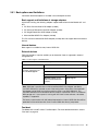
1
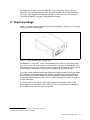
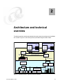
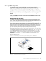
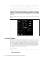
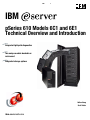
Front cover IBM pSeries 610 Models 6C1 and 6E1 Technical Overview and Introduction Integrated light path diagnostics Two unique models: deskside or rack mount Integrated storage options Volker Haug Scott Vetter ibm.com/redbooks International Technical Support Organization pSeries 610 Models 6C1 and 6E1 Technical Overview and Introduction October 2001 Take Note! Before using this information and the product it supports, be sure to read the general information in “Special notices” on page 27. First Edition (October 2001) This edition applies to the IBM ^ ™ pSeries™ 610 Models 6C1 and 6E1. Related software offerings include AIX® Version 4.3, product number 5754-C34, AIX 5L™ Version 5.1, product number 5765-E61, and all subsequent releases. Comments may be addressed to: IBM Corporation, International Technical Support Organization Dept. JN9B Building 003 Internal Zip 2834 11400 Burnet Road Austin, Texas 78758-3493 When you send information to IBM, you grant IBM a non-exclusive right to use or distribute the information in any way it believes appropriate without incurring any obligation to you. © Copyright International Business Machines Corporation 2001. All rights reserved. Note to U.S Government Users - Documentation related to restricted rights - Use, duplication or disclosure is subject to restrictions set forth in GSA ADP Schedule Contract with IBM Corp. Contents Contents . . . . . . . . . . . . . . . . . . . . . . . . . . . . . . . . . . . . . . . . . . . . . . . . . . . . . . . . . . . . . . . . iii Preface . . . . . . . . . . . . . . . . . . . . . . . . . . . . . . . . . . . . . . . . . . . . . . . . . . . . . . . . . . . . . . . . . .v The team that wrote this Whitepaper . . . . . . . . . . . . . . . . . . . . . . . . . . . . . . . . . . . . . . . . . . . .v Comments welcome. . . . . . . . . . . . . . . . . . . . . . . . . . . . . . . . . . . . . . . . . . . . . . . . . . . . . . . . vi Chapter 1. General description . . . . . . . . . . . . . . . . . . . . . . . . . . . . . . . . . . . . . . . . . . . . . 1.1 Minimum and optional features . . . . . . . . . . . . . . . . . . . . . . . . . . . . . . . . . . . . . . . . . . . . 1.2 Physical package . . . . . . . . . . . . . . . . . . . . . . . . . . . . . . . . . . . . . . . . . . . . . . . . . . . . . . 1.3 Enterprise racks . . . . . . . . . . . . . . . . . . . . . . . . . . . . . . . . . . . . . . . . . . . . . . . . . . . . . . . 1.3.1 IBM RS/6000 7014 Model T00 Enterprise Rack . . . . . . . . . . . . . . . . . . . . . . . . . . . 1.3.2 IBM RS/6000 7014 Model T42 Enterprise Rack . . . . . . . . . . . . . . . . . . . . . . . . . . . 1.3.3 Rack mounting rules for Model 6C1 . . . . . . . . . . . . . . . . . . . . . . . . . . . . . . . . . . . . 1.3.4 IBM 7316-TF1 Flat Panel Display Console . . . . . . . . . . . . . . . . . . . . . . . . . . . . . . . 1.3.5 VGA switch . . . . . . . . . . . . . . . . . . . . . . . . . . . . . . . . . . . . . . . . . . . . . . . . . . . . . . . 1.3.6 Cable management arm . . . . . . . . . . . . . . . . . . . . . . . . . . . . . . . . . . . . . . . . . . . . . 1 1 3 4 5 5 5 6 6 7 Chapter 2. Architecture and technical overview . . . . . . . . . . . . . . . . . . . . . . . . . . . . . . 2.1 Processor and cache . . . . . . . . . . . . . . . . . . . . . . . . . . . . . . . . . . . . . . . . . . . . . . . . . . 2.1.1 L1 and L2 cache . . . . . . . . . . . . . . . . . . . . . . . . . . . . . . . . . . . . . . . . . . . . . . . . . . 2.1.2 POWER3-II architecture . . . . . . . . . . . . . . . . . . . . . . . . . . . . . . . . . . . . . . . . . . . . 2.1.3 Copper and CMOS technology . . . . . . . . . . . . . . . . . . . . . . . . . . . . . . . . . . . . . . . 2.1.4 Processor deallocation . . . . . . . . . . . . . . . . . . . . . . . . . . . . . . . . . . . . . . . . . . . . . 2.1.5 Processor clock rate . . . . . . . . . . . . . . . . . . . . . . . . . . . . . . . . . . . . . . . . . . . . . . . 2.1.6 Processor part numbers . . . . . . . . . . . . . . . . . . . . . . . . . . . . . . . . . . . . . . . . . . . . 2.2 Memory . . . . . . . . . . . . . . . . . . . . . . . . . . . . . . . . . . . . . . . . . . . . . . . . . . . . . . . . . . . . . 2.2.1 Memory boot time deconfiguration . . . . . . . . . . . . . . . . . . . . . . . . . . . . . . . . . . . . 2.2.2 Memory interchange with other systems. . . . . . . . . . . . . . . . . . . . . . . . . . . . . . . . 2.3 System bus . . . . . . . . . . . . . . . . . . . . . . . . . . . . . . . . . . . . . . . . . . . . . . . . . . . . . . . . . . 2.3.1 Bus bandwidth . . . . . . . . . . . . . . . . . . . . . . . . . . . . . . . . . . . . . . . . . . . . . . . . . . . 2.4 PCI-bus, slots, and adapters . . . . . . . . . . . . . . . . . . . . . . . . . . . . . . . . . . . . . . . . . . . . . 2.4.1 32-bit versus 64-bit PCI slots . . . . . . . . . . . . . . . . . . . . . . . . . . . . . . . . . . . . . . . . 2.4.2 LAN adapters . . . . . . . . . . . . . . . . . . . . . . . . . . . . . . . . . . . . . . . . . . . . . . . . . . . . 2.4.3 Graphics accelerators . . . . . . . . . . . . . . . . . . . . . . . . . . . . . . . . . . . . . . . . . . . . . . 2.4.4 Internal storage attachments . . . . . . . . . . . . . . . . . . . . . . . . . . . . . . . . . . . . . . . . 2.5 Miscellaneous . . . . . . . . . . . . . . . . . . . . . . . . . . . . . . . . . . . . . . . . . . . . . . . . . . . . . . . . 2.5.1 Boot options and limitations . . . . . . . . . . . . . . . . . . . . . . . . . . . . . . . . . . . . . . . . . 2.6 Security . . . . . . . . . . . . . . . . . . . . . . . . . . . . . . . . . . . . . . . . . . . . . . . . . . . . . . . . . . . . . 2.7 Software requirements . . . . . . . . . . . . . . . . . . . . . . . . . . . . . . . . . . . . . . . . . . . . . . . . . . 9 10 10 10 11 11 12 13 13 14 14 14 14 14 15 15 15 15 16 17 18 18 Chapter 3. Availability, investment protection, and expansion. . . . . . . . . . . . . . . . . . . 3.1 High availability solution . . . . . . . . . . . . . . . . . . . . . . . . . . . . . . . . . . . . . . . . . . . . . . . . 3.2 Reliability, availability, and serviceability (RAS) features . . . . . . . . . . . . . . . . . . . . . . . 3.2.1 Light Path diagnostics . . . . . . . . . . . . . . . . . . . . . . . . . . . . . . . . . . . . . . . . . . . . . . 3.2.2 Service processor . . . . . . . . . . . . . . . . . . . . . . . . . . . . . . . . . . . . . . . . . . . . . . . . . 3.2.3 Hot plug power supplies . . . . . . . . . . . . . . . . . . . . . . . . . . . . . . . . . . . . . . . . . . . . 3.2.4 Hot plug fans . . . . . . . . . . . . . . . . . . . . . . . . . . . . . . . . . . . . . . . . . . . . . . . . . . . . . 3.2.5 Hot plug task . . . . . . . . . . . . . . . . . . . . . . . . . . . . . . . . . . . . . . . . . . . . . . . . . . . . . 3.3 Handheld based systems management . . . . . . . . . . . . . . . . . . . . . . . . . . . . . . . . . . . . 19 19 19 21 22 24 24 25 26 © Copyright IBM Corp. 2001 iii Special notices . . . . . . . . . . . . . . . . . . . . . . . . . . . . . . . . . . . . . . . . . . . . . . . . . . . . . . . . . . 27 IBM trademarks . . . . . . . . . . . . . . . . . . . . . . . . . . . . . . . . . . . . . . . . . . . . . . . . . . . . . . . . . . 28 Related Publications . . . . . . . . . . . . . . . . . . . . . . . . . . . . . . . . . . . . . . . . . . . . . . . . . . . . . System Publications . . . . . . . . . . . . . . . . . . . . . . . . . . . . . . . . . . . . . . . . . . . . . . . . . . . . . . . Referenced Web Sites . . . . . . . . . . . . . . . . . . . . . . . . . . . . . . . . . . . . . . . . . . . . . . . . . . . . . How to Get IBM Redbooks. . . . . . . . . . . . . . . . . . . . . . . . . . . . . . . . . . . . . . . . . . . . . . . . . . iv pSeries 610 Models 6C1 and 6E1 Technical Overview and Introduction 29 29 29 30 Preface This document provides a comprehensive single-source guide covering IBM® ^ ™ pSeries™ 610 Models 6C1 and 6E1 entry servers. Major hardware offerings are introduced and their prominent functions discussed. Professionals wishing to acquire a better understanding of IBM ^ pSeries products may consider reading this document. The intended audience includes: Customers Sales and marketing professionals Technical support professionals IBM Business Partners This document expands the current set of IBM ^ pSeries documentation by providing an ideal, comprehensive, desktop reference that offers a detailed technical description about the pSeries 610 Models 6C1 and 6E1. This publication does not replace the latest pSeries marketing materials and tools. It is intended as an additional source of information that, together with existing sources, may be used to enhance your knowledge of IBMs solutions for the UNIX marketplace. The team that wrote this Whitepaper This Whitepaper was produced by a worldwide specialist working at the International Technical Support Organization, Austin Center. Volker Haug is an Advisory I/T specialist. He has more than 14 years of experience in the I/T industry, the last 11 of which he devoted to IBM ^ pSeries and RS/6000® systems. He holds a degree in Business Management from the Berufsakademie in Stuttgart. Volker is the worldwide pSeries technical support community leader for IBM UNIX workstations and entry servers supporting IBM sales, Business Partners, and customers with pre-sales consultation and implementation of client/server environments. His areas of expertise include IBM UNIX workstations and servers, graphics, MCAD applications, and AIX® systems management. Based in Stuttgart, Germany, he is currently working for the Web Server Sales pSeries and RS/6000 pre-sales technical support organization covering the Europe, Middle East, and Africa Central Region. The project that created this document was managed by: Scott Vetter International Technical Support Organization, Austin Center Thanks to the following people for their contributions to this project: Dough Bloch IBM Austin Tom Campbell IBM Austin © Copyright IBM Corp. 2001 v Dale Dagitz IBM Austin Tesshu Flower IBM Canada John Hilburn IBM Austin Tenley Jackson IBM Dallas Stephen Lutz IBM Germany Paul Maybaum IBM Austin Bill Mihaltse IBM Somers Mace Miller IBM Austin Thoi Nguyen IBM Austin Jan Palmer IBM Austin Richard Talbot IBM Austin Ven Tenjarla IBM Austin Susan Tiner IBM Austin Roger Weekly IBM Austin Comments welcome Your comments are important to us! We want our Whitepapers to be as helpful as possible. Send us your comments about this Whitepaper or other Redbooks™ in one of the following ways: Use the online Contact us review redbook form found at: http://www.ibm.com/redbooks Send your comments in an Internet note to: [email protected] Mail your comments to the address on page ii. vi pSeries 610 Models 6C1 and 6E1 Technical Overview and Introduction 1 Chapter 1. General description The IBM® ^™ pSeries™ 610 Models 6C1 and 6E1 (referred to hereafter as the Model 6C1 and Model 6E1) are members of the 64-bit family of symmetric multiprocessing (SMP) UNIX servers from IBM and use state-of-the-art, 64-bit, copper-based, POWER3-II microprocessors. The Model 6C1 (product number 7028-6C1) is a rack-mounted server, the Model 6E1 (7028-6E1) is a tower server. Both models, manufactured in Rochester, Minnesota, USA and Dublin, Ireland, give you new tools for managing e-business, new application flexibility, and innovative technology, all designed to help you capitalize on the e-business revolution. Both models provide outstanding performance for all kinds of commercial and technical computing requirements, especially e-business, application or service providers, and database servers. Powered by the latest POWER3-II, 64-bit processors, the Models 6C1 and 6E1 will bring significant rewards to those customers desiring a server solution for their e-business requirements and incorporating the power of the Web into the operations of their organizations. The low cost, reliability, and remote systems management capabilities of these servers make them ideal for retail, wholesale distribution, financial services, insurance, healthcare, and other environments that support remote stores, branches, regional offices, and kiosks. Models 6C1 and 6E1 are systems that provide a growth path for existing pSeries or RS/6000® installations, such as the RS/6000 Model F50. 1.1 Minimum and optional features The Models 6C1 and 6E1 come with a minimum of one 64-bit 375 MHz POWER3-II processor, 512 MB error checking and correcting (ECC) synchronous dynamic random access memory (SDRAM), a 48X maximum speed CD-ROM drive, a 1.44 MB 3.5” diskette drive, one 18.2 GB 10,000 RPM Ultra3 (also known as Ultra160) SCSI disk drive, two integrated 10/100 Mbps Ethernet controllers (both RJ45), two Ultra3 SCSI controllers for internal and external attachments, and an operator panel. The operator panel has a 2 x 16 backlit LCD for system status and diagnostic information. The systems offer integrated ports © Copyright IBM Corp. 2001 1 for keyboard, mouse, one parallel, and three serial. Only the rack-mounted Model 6C1 has serial port one accessible from an RJ48 connection on front as well as the standard 9 pin port on the rear of the system. When one port is used, the other is disabled. The serial port 1, accessible on front, has a higher priority than serial port 1 on the rear. Note: If you want to attach a 25-pin serial cable, you need to order the Serial Port Converter Cable, 9-Pin to 25-Pin (# 3925). This is not shipped with the system unit. An RJ45 to 9-pin converter cable is shipped automatically with every Model 6C1, which can be used for the RJ48 front serial port. The additional connections provided by the RJ48 connector are currently not used. One or two POWER3-II 64-bit processors are connected to an IBM designed high performance memory and system control chip set. These processors may be ordered in one of the following two configurations: 375 MHz processor, including 4 MB of Level 2 (L2) ECC cache. 450 MHz processor, including 8 MB of L2 ECC cache. IBM has implemented copper technology in its SMP workstations and servers. Refer to “Copper and CMOS technology” on page 11 for more information. The memory can be expanded up to 8 GB for improved performance and exploitation of 64-bit addressing, as used in large database applications. The Models 6C1 and 6E1 contain ten media bays. The six front-accessible, hot-swappable disk drive bays can accommodate up to 218.4 GB of disk storage using 36.4 GB disk drives. Media bay 0 is occupied by the operator panel but has the default disk drive (non-hot swap) mounted behind the operator panel. Media bay 1 can be used for: An additional IDE CD-ROM drive A DVD-RAM drive An optional non-hot-swap disk (requires the media bay disk drive mounting kit to install a SCSI disk drive in the media bay) An optional media device, such as a 4 mm or 8 mm tape drive Media bay 2 holds the default IDE CD-ROM drive or can hold a DVD-RAM drive, instead of the default CD-ROM. Media bay 3 is occupied by a diskette drive. A mouse or one of several national keyboards are used as input devices. For the rack-mounted Model 6C1, we recommend that you use the 7316-TF1 Flat Panel Console in combination with the appropriate console switch to manage several systems in a rack. To help ensure that strategic applications remain available 24 x 7, the Models 6C1 and 6E1 feature an integrated service processor that constantly monitors the systems' vital signs. In the event of a malfunction, the service processor is capable of calling home by automatically dialing out to an IBM service center, often before any problem is apparent to users or system administrators. 2 pSeries 610 Models 6C1 and 6E1 Technical Overview and Introduction The Models 6C1 and 6E1 are the first IBM UNIX servers that contain built-in Light Path Diagnostics. This technology provides LEDs physically located on key system components, assisting in quick diagnosis and resolution of problems, should they arise. Please refer to “Light Path diagnostics” on page 21 to get detailed information. 1.2 Physical package Figure 1-1 on page 3 shows the package layout for the Model 6C1, and Figure 1-2 on page 4 shows the same for the Model 6E1. Figure 1-1 pSeries 610 Model 6C1 - package layout The Model 6C1 is a 5U (EIA)1 19 inch rack-mounted system and has a size of 426 mm W x 617 mm D x 215 mm H (16.8 inches W x 24.0 inches D x 8.5 inches). The Model 6E1 has a tower package. Its size is 215 mm W x 617 mm D x 426 mm H (8.5 inches W x 24.0 inches D x 16.8 inches H). Both systems have a maximum weight of 43.1 kg (94.8 pounds). The system comes preconfigured with the features the customer ordered, leaving one media bay available for customer expansion. Any devices in the media bays are connected to the internal Ultra3 SCSI controller (depending on the configuration selected, additional cables may be required to complete an order, see 2.4.4, “Internal storage attachments” on page 15 for more information). To connect external SCSI devices to the external Ultra3 SCSI adapter’s VHDCI2, order feature code # 2118 (mini-68 pin VHDCI to 68 pin). This 0.3 m long cable (P/N 76H0518) is not included with the minimum system configuration. 1 2 One EIA (Electronic Industries Association Unit) is 44.45 mm (1.75”). Very High Density Cable Interconnect (VHDCI) Chapter 1. General description 3 Figure 1-2 pSeries 610 Model 6E1 - package layout 1.3 Enterprise racks The following description provides an overview of racks available from IBM in which the Model 6C1 can be mounted. At the time of writing, no feature is available to convert a tower model to a rack mount model. Check with your IBM representative to determine the availability of this feature. The Enterprise Rack Models T00 and T42 are 19-inch wide racks for general use with pSeries and RS/6000 rack-based or rack drawer based systems. The rack provides increased capacity, greater flexibility, and improved floor space utilization. Special specifications are required if you want to install an IBM pSeries or RS/6000 system in a non-pSeries or non-RS/6000 racks or cabinets. It is ultimately your responsibility to ensure that the installation of the drawer in your preferred rack or cabinet results in a configuration that is stable, serviceable, safe, and compatible with the drawer requirements for power, cooling, cable management, weight, and rail securement. To determine compliance to the following specifications, you may need to get rack specification and certification information from your rack manufacturer’s representative. IBM Site Hardware and Planning Information, as well as specific product Installation Guides, will contain more detailed product information. Your IBM Sales Representative or Installation Planning Representative will have access to these documents. Additionally, your IBM Branch Office Specialist or your IBM Installation Planning Representative may be able to assist you, as needed, in verifying that your non-pSeries rack or cabinet complies with the requirements in this specification. 4 pSeries 610 Models 6C1 and 6E1 Technical Overview and Introduction Note: You can get the latest available IBM ^ pSeries Specifications For Installations in A Non-pSeries Rack or Cabinet document from this IBM internal location: http://wwas.raleigh.ibm.com/safety/racks.pdf 1.3.1 IBM RS/6000 7014 Model T00 Enterprise Rack The 1.8 m (71 inches) Model T00 is compatible with past and present pSeries and RS/6000 racks, and is designed for use in all situations that have previously used the older rack models R00 and S00. The T00 rack has the following features: 36 EIA units (36 U) of usable space. Optional removable side panels. Optional classic or sculptured front door. Optional side-to-side mounting hardware for joining multiple racks. Increased power distribution and weight capacity. Standard black or optional white color. Optional reinforced (ruggedized) rack feature provides added earthquake protection with modular rear brace, concrete floor bolt-down hardware, and bolt-in steel front filler panels. Model T00 supports both AC and DC configurations. Weight: – T00 Base Empty Rack: 244 kg (535 pounds) – T00 Full Rack: 816 kg (1795 pounds) 1.3.2 IBM RS/6000 7014 Model T42 Enterprise Rack The 2.0 m (79.3 inches) Model T42 is the rack that will address the special requirements of customers who want a tall enclosure to house the maximum amount of equipment in the smallest possible floor space. The features that differ in the Model T42 rack from the Model T00 include the following: 42 EIA units (42 U) of usable space. Model T42 supports AC only. Weight: – T42 Base Empty Rack: 261 kg (575 pounds) – T42 Full Rack: 930 kg (2045 pounds) 1.3.3 Rack mounting rules for Model 6C1 There are some rules that should be considered when mounting drawers into a rack. These are as follows: The Model 6C1 is designed to be placed at any location in the rack. Any remaining space in the rack can be used for storage, such as 7133-D40 or 2104-DU3, if desired. According to the IBM ^ pSeries 610 Models 6C1 and 6E1 Installation Guide, SA38-0597, you have to remove the blue wheel-shaped knobs from the server after you have installed the Model 6C1 in a rack. Store the knobs in a safe place to use them in case Chapter 1. General description 5 you need to remove the server from the rack at a later time. If you are not able to find them at a later time, you will need to order two of part number 09N7997. A Model 6C1 is 5 U in height, so a maximum of seven Model 6C1s fit in a T00 rack, or you can put eight Model 6C1s in a T42 rack. Each Model 6C1 is shipped with a rack mounting template, which helps you to easily place the cage nuts in the correct position in a rack. 1.3.4 IBM 7316-TF1 Flat Panel Display Console For rack-mounted systems, there is the ability to install a system console to the hardware mounted in a system rack. This monitor combines a bright 15-inch viewable image and 1024 x 768 addressability with a space-saving package design. Using thin film transistor (TFT) LCD technology, the T54A features a 304.1 mm x 228.1 mm viewable area with flicker-free display of the primary XGA-mode (1024 x 768) and full-screen support for other common Video Electronics Standards Association (VESA) and industry modes. The 7316-TF1 console has the following attributes: 3 EIA units (3 U) IBM T54A Flat Panel Monitor Flat panel monitor rack-mounted Rack keyboard tray IBM Space Saver 2 Keyboard that mounts in the Rack Keyboard Tray and is available in sixteen language configurations (track point mouse is integral to keyboard) Note: The 7316-TF1 requires a GXT135P Graphics Adapter (# 2848) to be connected to a Model 6C1. 1.3.5 VGA switch The VGA switch for the IBM 7316-TF1 Flat Panel Display Console allows users to control multiple servers from a single console. This dual-user switch allows attachment of one or two consoles, one of which must be an IBM 7316-TF1. Either console can control any one of the eight servers, except that both consoles cannot talk to the same server at the same time. An easy to use graphical interface, supported in six languages (English, French, Spanish, German, Italian, or Brazilian Portuguese), allows fast switching between systems. Using multiple switches in a two-level cascade arrangement, as many as 64 systems can be controlled from a single point. The VGA switch is only 1 EIA unit (1U) high and can be mounted in the same tray as the 7316-TF1 Rack Console, thus conserving valuable rack space. It supports a maximum video resolution of 1600 x 1280, which facilitates the use of graphics-intensive applications and large monitors. To help minimize cable clutter, multi-connector cables in lengths of 7, 12, and 20 feet are available. These cables can be used to connect the graphics adapter (required in each attached system), keyboard port and mouse port of attached servers to the switch or to connect between switches in a tiered configuration. 6 pSeries 610 Models 6C1 and 6E1 Technical Overview and Introduction 1.3.6 Cable management arm The Model 6C1 is shipped by default with a cable management arm. You can route all cables through the cable management arm, attaching the cables to the arm with the hook and loop fastener strips provided. The wraps are provided for additional cable management. Figure 1-3 shows the cable management arm. As the drawer is moved on its rails into the service position, the arms expand or collapse, actively managing the cables. A cable retention clip located on the rear of the server provides a reliable anchor for the cable so that the drawer movement does not accidentally detach them. Figure 1-3 Cable management arm for Model 6C1 Chapter 1. General description 7 8 pSeries 610 Models 6C1 and 6E1 Technical Overview and Introduction 2 Chapter 2. Architecture and technical overview The following sections provide more detailed information about the architecture of the Models 6C1 and 6E1. Figure 2-1 shows the high level system block diagram of both models. Processor Card POWER3-II 375 MHz or 450 MHz Processor Card 250 MHz w/ 375 MHz 225 MHz w/ 450 MHz 4 MB L2 w/ 375 MHz 8 MB L2 w/ 450 MHz 6xx Data Bus Addr/Cntl 375 MHz or 450 MHz 225 MHz w/ 450 MHz 4 MB L2 w/ 375 MHz 8 MB L2 w/ 450 MHz 16 Bytes @ 93.75 MHz w/ 375 MHz 16 Bytes @ 93.75 MHz w/ 375 MHz Memory Data Bus 250 MHz w/ 375 MHz 16 Bytes @ 90 MHz w/ 450 MHz 6xx Address Bus Memory Address POWER3-II Data 16 Bytes @ 90 MHz w/ 450 MHz 6xx-MX Bus 66 MHz Memory 512 MB - 8 GB System Planar I/O Planar Integrated Service Processor PCI Bridge ISA Bridge SCSI Controller 3rd serial port Super I/O IDE CDROM 10/100 Ethernet 10/100 Ethernet Internal Ultra3-SCSI External Ultra3-SCSI 2 PCI Slots 32 bit 33 MHz 5v PCI Bridge 1 PCI Slots 64 bit 33 MHz 5v 2 PCI Slots 64-bit 50 MHz 3.3v Figure 2-1 Model 6C1 and 6E1 - high-level system block diagram © Copyright IBM Corp. 2001 9 2.1 Processor and cache The IBM® ^ ™ pSeries™ 610 Models 6C1 and 6E1 have two processor card slots and can accommodate two different processor cards, a 1-way 375 MHz or a 1-way 450 MHz. Note that slot 1 must have a processor card installed for normal operation. If your system unit uses two processor cards, both processor cards must be of the same clock speed. Note: Installing a processor card into your system unit may require updating the firmware. A diskette or CD-ROM is included with your new processor card if that is required. Check also the following Web page for the latest available firmware: http://www.rs6000.ibm.com/support/micro/ 2.1.1 L1 and L2 cache Models 6C1 and 6E1 use a 64 KB data and a 32 KB instruction 128-way set associative L1 cache. The size of both data and instruction cache reduces the number of cache misses, results in more cache hits, and maximizes performance. Both data and instruction cache are parity protected. The L1 cache is effectively supplemented by a 4 MB 4-way set associative L2 cache, which is located on the 375 MHz processor card (8 MB for the 450 MHz processor card). The speed of the L2 cache is dependent upon the processor speed. The POWER3-II uses a private 32-byte L2 cache bus, operated at 250 MHz with the 375 MHz processor card (2:3 ratio) and operated at 225 MHz with the 450 MHz processor card (1:2 ratio). Both the enhanced clock speed and 4-way set associative L2 cache improve cache efficiency. The L2 controller uses a least recently used (LRU) algorithm to avoid replacing recently used cache data and a set prediction mechanism that helps reduce L2 cache misses. The L2 cache uses a direct mapped cache methodology. There is a dedicated external interface to the L2 cache not shared with the 6XX bus. This allows concurrent access to both the L2 cache and the 6XX bus. 2.1.2 POWER3-II architecture The POWER3-II processor offers technical leadership for floating point applications and high-performance numeric intensive computing (NIC) workstations by integrating two floating-point, three fixed-point, and two load/store execution units in a single 64-bit POWER3 implementation. Table 2-1 lists some of the technical features of the POWER3-II processors. Table 2-1 Technical features of POWER3-II 10 Description POWER3-II Chip Die Size 163 mm2 Transistors 23 million Power Avg/Max 26W/33W@375 MHz, 31W/42W@450 MHz CMOS Technology 7S, 6 layers metal, copper interconnect Lithography 0.22 µm pSeries 610 Models 6C1 and 6E1 Technical Overview and Introduction 2.1.3 Copper and CMOS technology Copper is a superior conductor of electricity, making it possible to shrink electronic devices even further while increasing performance. It has less resistance than aluminum and, therefore, allows designs that transmit electrical signals faster. However, it does not mix as well with silicon, the base material of semiconductor chips. IBM researchers found a way to put a microscopic barrier between the copper and silicon in a way that actually reduced the number of steps needed to complete a chip. With this development, IBM is able to squeeze down the widths of copper wires to the 0.2-micron range from the current 0.35-micron widths - a reduction far more difficult for aluminum. A single POWER3-II chip contains about 400 meters of copper wiring. This technology, called CMOS 7S, is the first to use copper instead of aluminum to create the circuitry on silicon wafers. Copper wires conduct electricity with about 40 percent less resistance than aluminum. That improves processor performance and reliability while using less power and producing less heat, thus conserving energy for both operations and cooling. 2.1.4 Processor deallocation In general, there are two options available to deallocate a processor within an SMP system, which are described in more detail in the following sections: 1. Processor Boot Time Deconfiguration 2. Processor Run-Time Deconfiguration (Dynamic Processor Deallocation) The capability of Dynamic Processor Deallocation is only active in systems with more than two processors, because device drivers and kernel extensions, which are common to multi-processor and uniprocessor systems, would change their mode to uniprocessor mode with unpredictable results. Therefore, it could not be used in the Models 6C1 and 6E1. Processor boot time deconfiguration within an SMP system Processor boot time deconfiguration within an SMP system is a function implemented in the system and service processor firmware of the Models 6C1 and 6E1 for deallocating a processor from the system configuration at boot time. The objective is to minimize system failure or data integrity exposure due to a faulty processor. The processor that is deconfigured remain offline for subsequent reboots until the faulty processor hardware is replaced. This function provides the option for a user to manually deconfigure or re-enable a previously deconfigured processor using the Service Processor menu. Note: Processor cards only can physically be removed when the power is turned off to the entire system. If the system processor in slot 1 (P1-C1) has been deconfigured by the system, the service processor will prevent the system from booting. How to disable the second processor manually A additional processor in Models 6C1 and 6E1 can be disabled only within the Service Processor menus. There is no need to remove them from the system. The cpu_state command, used on the micro-channel SMP servers, is not supported on the PCI-based systems. To determine if a processor is enabled or disabled, use the following AIX® commands: sar command (requires bos.acct fileset to be installed): Chapter 2. Architecture and technical overview 11 # sar -P ALL 2 AIX volker@colt 3 4 000AAFDD4C00 09/18/01 07:30:44 cpu %usr %sys %wio %idle 07:30:46 0 0 0 0 100 1 0 0 0 100 0 0 0 100 In the previous example, two configured processors are shown in the cpu column. lsattr command. The AIX 5L™ Version 5.1 is output shown: # lsattr -E -l proc0 state enable Processor state False type PowerPC_POWER3 Processor type False frequency 375000000 Processor Speed False state enable means that processor 0 is enabled. # lsattr -E -l proc1 state disabled Processor state False type PowerPC_POWER3 Processor type False frequency 375000000 Processor Speed False state faulty means that processor 1 is disabled. Note: The processor(s) remain deconfigured until manually reconfigured. 2.1.5 Processor clock rate The different processor cards and the processor speeds can be identified by the following three methods: 1. SMS Display Configuration menu. To start and enter the graphical System Management Services, turn on or restart the computer, and press the F1 key after the keyboard icon displays during startup and before the tone. For the text-based verion of SMS, press the 1 key. 2. Use the lsattr -El procX command (where X is the number of processor, for example, proc0 is the first processor in a system). The output of the command is similar to the following: state enable Processor state False type PowerPC_POWER3 Processor type False frequency 375000000 Processor Speed False The output of the lsattr command has been expanded with AIX 5L Version 5.1 and shows now also the processor clock rate. 3. Use the lscfg -vp | more command. Page down to the Processor Card entry and search for the Product Specification (ZC) entry. This gives you detailed information about: PS Processor Clock Speed in Hz, ASCII coded hexadecimal LB L2 Bus Speed in Hz, ASCII coded hexadecimal SB System Bus Speed in Hz, ASCII coded hexadecimal NP Number of Processors on Card, ASCII coded hexadecimal L2 L2 Size in number of Kilobytes, ASCII coded hexadecimal PF Processor card failure code, ASCII coded decimal The following is an example of the processor card information: Processor Card: Part Number.................09P3481 12 pSeries 610 Models 6C1 and 6E1 Technical Overview and Introduction EC Level....................H10826 Serial Number...............0000000026 FRU Number..................09P3666 Manufacture ID..............1980 Version.....................RS6K Product Specific.(ZC).......PS=00165A0BC0,LB=000EE6B280, SB=00059682F0,NP=01,L2=04096, PF=754,SV=3,VR=1,ER=00 Physical Location: P1-C1 For example, PS shows the processor speed in hex-number digit as follows: a. (0x00165A0BC0 = 375000000 Hz = 375 MHz). b. (0x001AD27480 = 450000000 Hz = 450 MHz). 4. Use the lscfg -vp | more command. Page down to the Processor Card entry and search for the PF entry under the Product Specification (ZC) section. If you see PF=754, then you have a 375 MHz card (L2 = 4 MB); if you see PF=758, then you have a 450 MHz card (L2 = 8 MB). 2.1.6 Processor part numbers Due to manufacturing improvements, the part number of the processor cards might change. You can determine the part number of the current installed processor cards using the following method: 1. Enter the AIX command: lscfg -vp | more 2. Page down to the Processor Card entry and search for the Product Specification (ZC) entry. 3. Determine the appropriate part number. 2.2 Memory The memory subsystem of the Models 6C1 and 6E1 support a 128 bit data path to memory along with an 8-bit ECC code that provides single bit correction, double bit error detection, and 4-bit packet error detection. A minimum of 512 MB of memory is required, and can be expanded to a maximum of 8 GB SDRAM. Figure 2-2 Memory card Dual inline memory modules (DIMMs) must be ordered and installed in matched (size and speed) pairs on the memory card. They are available in two sizes: 256 MB and 512 MB. The memory card can accommodate eight pairs of DIMM sockets. The supported method to install DIMMs is to start at the bottom of each card (card slot J1 and J2) and then move up. The system design gives you the flexibility to mix 256 MB and 512 MB SDRAM DIMM features on the Memory Expansion Kit without affecting performance. Chapter 2. Architecture and technical overview 13 2.2.1 Memory boot time deconfiguration Memory boot time deconfiguration is a function implemented in the service processor firmware for removing a memory segment or DIMM from the system configuration at boot time. The objective is to minimize system failures or data integrity exposure due to faulty memory hardware. The memory segment or DIMM that is deconfigured remains offline for subsequent reboots until the faulty memory hardware is replaced. This function provides the option for the user to manually deconfigure or re-enable a previously deconfigured memory segment or DIMM using the Service Processor menu. Memory can also be decreased with AIX using the rmss command. This is useful for certain benchmark simulations. Note: Memory cards can physically be removed only when the power is turned off to the entire system. 2.2.2 Memory interchange with other systems The 2x256 MB DIMMs (# 4120) or 2x512 MB DIMMs (# 4121) options can be interchanged with the RS/6000® Models 44P-170, 44P-270, and the IBM ^ pSeries 640 Model B80. 2.3 System bus The 6XX bus or system bus is optimized for high-performance and multiprocessing performance. The bus is fully parity checked and each memory or cache request is range checked and positively acknowledged for error detection. Any error will cause a machine check condition and is logged in the AIX error log. The system bus speed is operated at 93.75 MHz with the 375 MHz processor card (1:4 ratio), and at 90 MHz with the 450 MHz processor card (1:5 ratio). 2.3.1 Bus bandwidth The following are the theoretical maximum bandwidths, as applicable for an 2-way 450 MHz SMP configuration: Memory bandwidth: 1.44 GB/s Processor bandwidth: 1.44 GB/s Bandwidth of the PowerPC® 6xx bus used to the I/O interface: 528 MB/s 2.4 PCI-bus, slots, and adapters The IBM ^ pSeries 610 Models 6C1 and 6E1 are compliant with Revision 2.1 of the peripheral component interconnect (PCI) specifications and implement two peer PCI busses: a 32-bit data bus operating at 33 MHz and a 64-bit bus operating at 50 MHz. There are five PCI slots available. Slots one and two are 64-bit capable and can run up to speeds of 50 MHz. Slot three is 64-bit capable, and slots four and five are 32-bit. Slots three, four, and five run at 33 MHz. A variety of graphics, SCSI, Fibrechannel, LAN, WAN, asynchronous, and SSA adapter cards can be installed in the Models 6C1 and 6E1. 14 pSeries 610 Models 6C1 and 6E1 Technical Overview and Introduction Note: Please refer to the PCI Adapter Placement Reference, SA38-0538, to find detailed information on where to plug in your adapters. Hot plug capabilities for PCI adapters are not supported on the Models 6C1 and 6E1. However, they are available within the IBM ^ pSeries and RS/6000 product line. The following specific systems support hot plug PCI capabilities at the time of writing: RS/6000 Model F80 RS/6000 Model H80 RS/6000 Model M80 RS/6000 SP™ Expansion I/O Units IBM ^ pSeries 620 Models 6F0 and 6F1 IBM ^ pSeries 660 Models 6H0 and 6H1 IBM ^ pSeries 660 Model 6M1 IBM ^ pSeries 690 Model 681 More specific information about selected adapters is provided in the next sections. 2.4.1 32-bit versus 64-bit PCI slots Choosing between 32-bit and 64-bit slots influences slot placements and affects performance. Higher-speed adapters use 64-bit slots because they can transfer 64 bits of data in each data transfer phase. 32-bit adapters can typically function in 64-bit slots; however, 32-bit adapters still operate in 32-bit mode and offer no performance advantages in a 64-bit slot. Likewise, most 64-bit adapters can operate in 32-bit PCI slots, but will operate in 32-bit mode at a reduced performance potential. 2.4.2 LAN adapters As the Models 6C1 and 6E1 are considered to be a server they have to be connected through the local area network (LAN). LAN connection options include: Ethernet, Token-Ring, and ATM. IBM support a installation with NIM using Ethernet and Token-Ring adapters (use chrp as platform type). 2.4.3 Graphics accelerators The IBM ^ pSeries 610 Models 6C1 and 6E1 are servers and are not intended to serve as a workstation. Therefore, the GXT135P is the only adapter of choice. This adapter offers 2D functionalities for business graphics or Internet applications. 2.4.4 Internal storage attachments The default disk drive is mounted behind the operating panel in a bolt-in DASD bay. Media bay 1 can also be used for a tape drive or a additional disk. Media bay 2 must have a CD-ROM or DVD-RAM device installed. You have to place the smallest capacity disk drive first, then place DASD with next highest capacity. Install the disk drive in ascending order capacity until all disks are in place. All disk drives and media devices are driven by the internal integrated SCSI port only. Chapter 2. Architecture and technical overview 15 Note: On the Model 6C1 the SCSI slots of the hot swap six pack are numbered from 1 to 6, right to left. On the model 6E1 they are numbered 1 to 6, top to bottom. Table 2-2 give you detailed information about how you can connect internal SCSI devices to your system. Table 2-2 SCSI cable configurations Configuration options, a combination of: SCSI devices in media bay 0 or 1. Zero up to six hot swap disk drives to be installed in the six pack enclosure. One internal SCSI disk in the media bay 0 One internal disk drive could be installed in media bay 0 mounted behind the operator panel and zero up to six hot plug disks could be installed in the six pack. You will need the SCSI 2-Drop Connector Cable (# 4247) to attach the drives to the system. One internal SCSI disk only in media bay 0 and a second internal SCSI disk in media bay 1. The first internal disk drive could be installed in media bay 0 mounted behind the operator panel. The second internal disk drive can be mounted in media bay 1 and requires the media bay disk drive mounting kit. You will need the SCSI Connector Cable and Repeater Card (# 4248) and the SCSI 3-Drop Connector Cable (# 4249) to attach the drives to the system. Zero or one internal SCSI disk in media bay 0 and one tape drive (4 mm or 8 mm) in media bay 1. One internal disk drive could be installed in media bay 0 mounted behind the operator panel. The 4 mm or 8 mm tape drive needs to be mounted in media bay 1. You will need the SCSI Connector Cable and Repeater Card (# 4248) and the SCSI 3-Drop Connector Cable (# 4249) to attach the drives to the system. Zero or one internal SCSI disk in media bay 0 and one SCSI DVD-RAM drive in media bay 1. One internal disk drive could be installed in media bay 0 mounted behind the operator panel. The SCSI DVD-RAM drive needs to be mounted in media bay 1. You will need the SCSI Connector Cable and Repeater Card (# 4248) and the SCSI 3-Drop Connector Cable (# 4249) to attach the drives to the system. 2.5 Miscellaneous The following selected information about ISA, USB, Boot support, NEBS compliance, and HMT is given in the sections below. At the time of writing, the following are not supported: Industry standard architecture (ISA) adapters Universal Serial Bus (USB) adapters Network Equipment Building System (NEBS) requirements Hardware multi-threading (HMT) 16 pSeries 610 Models 6C1 and 6E1 Technical Overview and Introduction 2.5.1 Boot options and limitations Information about boot options is included in the subsequent sections. Boot support and limitations of storage adapters At the time of writing, the following adapters support external boot for the Models 6C1 and 6E1: PCI Dual Channel Ultra3 SCSI Adapter (# 6203) PCI Universal Differential Ultra SCSI Adapter (# 6204) PCI Single-Ended Ultra SCSI Adapter (# 6206) Advanced SerialRAID Plus Adapter (# 6230) The PCI 4-Channel Ultra3 SCSI RAID Adapter (# 2498) does not support boot from external devices. Internal devices Boot support is available for every internal SCSI disk. External devices Table 2-3 provides a map that enables you to determine if boot is supported in external storage devices. Table 2-3 Boot support - external devices Does the PCI card have RAID functionality? Yes No The PCI card is seen as a controller and therefore we have no boot support. The PCI card is seen as a adapter. Does the external devices have RAID functionality? Yes No No boot support (except Advanced SerialRAID Plus adapter) Boot support Note: SSA boot is possible from an Advanced SerialRAID Plus Adapter, provided a non-RAID SSA disk is included as part of the configuration. Other disks associated with the adapter can be RAID, but at least one disk must be a non-RAID SSA disk. The non-RAID SSA disk can be located under the covers of a processor unit or in an external SSA storage unit. If your system is running with AIX 4.3.3 or later software, native boot capability is supported. For factory system orders with AIX preload requested, an internal SCSI disk drive will be preloaded as the native boot disk, even if internal SSA disk drive(s) are present. Fast boot The Models 6C1 and 6E1 offer a Fast Boot option. For more detailed information, refer to “Fast boot” on page 23. Chapter 2. Architecture and technical overview 17 2.6 Security To prevent the system from unauthorized booting from CD-ROM, you can set up a power-on-password (POP) or a privileged-access password (PAP). In order to protect the system from unauthorized users removing the battery to delete POP and PAP, you can lock the Model 6E1 with a key lock on the front cover, which protects your side cover as well as the hot-swap disk drives and other media bays from unauthorized access. The key lock is not available for the Model 6C1, as this system is to be considered as a rack-mounted server in a secure environment. 2.7 Software requirements The Models 6C1 and 6E1 require AIX Version 4.3.3, with 4330-09 recommended maintenance package (APAR IY22024) or later, or AIX 5L Version 5.1, with 5100-01 maintenance package (APAR IY21957) or later. In order to install the systems from CD-ROM, you need: AIX Version 4.3.3 Boot media: AIX 4.3.3 5765-C34 dated 9/2001 (CD# LCD4-0286-07) or later. Update CD-ROM: AIX 9/2001 4.3 Update CD (CD# LCD4-0995-14) or later. AIX 5L Version 5.1 Boot media: AIX 5L for POWER V5.1 5765-E61 dated 9/2001 (CD# LCD4-1061-01) or later. Update CD-ROM: AIX 9/2001 5.1 Update CD (CD# LCD4-1103-01) or later. You can also download the actual maintenance level from the Internet to install the machine using the Network Install Manager (NIM). The URL to obtain an AIX Version 4.3 maintenance level is: http://techsupport.services.ibm.com/rs6k/fixes.html Instructions on how to obtain AIX 5L service is available at this site. If you have problems downloading the latest maintenance level, ask your IBM Business Partner or IBM Representative. IBM anticipates 64-bit native Linux support on these servers by the First Quarter of 2002. 32-bit native Linux support is not available for the Models 6C1 and 6E1. 18 pSeries 610 Models 6C1 and 6E1 Technical Overview and Introduction 3 Chapter 3. Availability, investment protection, and expansion The following sections provide more detailed information about configurations, upgrades, and design features that will help you lower your cost of ownership. 3.1 High availability solution For even greater availability and reliability, the Models 6C1 and 6E1 also support IBM® High Availability Cluster Multiprocessing (HACMP) software, the leading UNIX disaster recovery clustering solution. This solution, when combined with applications that meet IBM clusterProven standards, provides a superior base for high availability, an essential ingredient of e-commerce. 3.2 Reliability, availability, and serviceability (RAS) features RAS features, such as redundant power supplies or N+1 hot-plug fans, are important for the availability of your server. A few RAS features of the Models 6C1 and 6E1 are covered in the next sections. At the time of writing there are other additional RAS features available in some specific pSeries systems that are not supported in the Models 6C1 and 6E1. They are listed as follows: Chipkill Chipkill™ memory is a technology from IBM that protects a server from any single memory chip failure and multibit errors from any portion of a single memory chip. Memory chip failures can cause server system crashes that can result in the permanent loss of business data. Dynamic Processor Deallocation The capability of Dynamic Processor Deallocation is only active in systems with more than two processors, because device drivers and kernel extensions, which are common to multi-processor and uniprocessor systems, would change their © Copyright IBM Corp. 2001 19 mode to uniprocessor mode with unpredictable results. Therefore, it could not be used in the Models 6C1 and 6E1. Capacity Upgrade on Demand (CUoD) Capacity Upgrade on Demand (CUoD) is a new feature that allows you to have inactive processors installed on your system, which can be made active quickly and as easily as your business needs require. Table 3-1 gives you a detailed overview of the RAS features by the pSeries family: Table 3-1 RAS features by the pSeries family RAS feature description pSeries system p610 p620 p640 p660 p680 p690 x x x x x Rigid planar packaging x x Soldered DRAMs x x x x Soft memory scrubbing x x Memory bit steering x x x x x Pin or connector guidance First failure data capture x Chipkill ECC memory ECC memory and caches x x x x x x x x x Dynamic processor deallocation x x x x x Hot-plug PCI slots x x x Hot-plug blowers and fans x x x x x x Hot-plug power supplies x x x x x x N+1 redundancy power, fans, blowers x x x x x x Hot-swappable disk drives x x x x x Service processor x x x x x x HACMP™, HAGEO, GeoRM support x x x x x x x x x x x x NEBS 3 compliance for harsh environments Dual line power cords x Light Path servicing Light Path diagnostics x x Logical partitioning (LPAR) Remark: (x means available) 20 x pSeries 610 Models 6C1 and 6E1 Technical Overview and Introduction x x 3.2.1 Light Path diagnostics The Models 6C1 and 6E1 are the first IBM UNIX servers that implement Light Path diagnostics technology. Light Path LEDs provide an obvious and intuitive means to positively identify the failing Field Replaceable Unit (FRU) through a path of light emitting points, starting on the exterior of the system (System Attention LED), located on the front of the system (also on the rear of rack mounted 6C1), and ending with a LED at or near the failing FRU. Correlation of the LED layout and the failing component is straightforward. Intermediate light points lead you to the area or subassembly of the machine where the failing FRU is located. Initially, for the Models 6C1 and 6E1, the fault LEDs will be implemented with only two LED states (ON and OFF). Attention and Light Path LEDs The attention and Light Path LEDs provide a means to identify failing components in your server. Attention LEDs are located on the front and rear of the system to make it easy for an on-site technician to quickly locate the system requiring attention. When a failing component is detected in your server, the attention LED is turned on. To further help you identify the failing component, go to the indicator panel inside the server and check which LEDs are lit on the indicator panel. After you have replaced the failing part you have to manually turn off the attention light using the service processor submenu or invoke the online diagnostics with the diag command (as discussed in the following). Enter diag and press Enter to continue. Then from the Function Selection main menu select Task Selection (Diagnostics, Advanced Diagnostics, Service Aids, etc.). Scroll down and select Log Repair Action. Select the device that was repaired (if the device is not listed, select sysplanar0). This will turn off the attention and Light Path LEDs. For more detailed information refer to the IBM ^ pSeries 610 Models 6C1 and 6E1 User’s Guide, SA38-0598. System indicator panel Figure 3-1 shows where you can find the system indicator panel in a Model 6C1. Figure 3-1 System indicator panel in a Model 6C1 Chapter 3. Availability, investment protection, and expansion 21 You can access the indicator panel without any tools. The panel provides enough information to identify the area that needs attention. The panel contains a group of amber LEDs that indicate which functional area of the system is experiencing the fault (such as Power, Processor cards, Memory, or Fans). If one of these LEDs is on, the user or service representative is directed to the physical area of the server, where they will find an additional LED on, indicating that the component is responsible for the current fault. In addition to the indicator panel or display, individual LEDs are located on or near the failing components. The LEDs are either on the component itself or on the carrier of the component (memory card, fan, memory module, or processor card(s)). The LEDs are amber, except for the power supplies. For the power supplies, two green LEDs indicate the fault condition for the power supply. Figure 3-2 on page 22 shows the LEDs on the system indicator panel, which is located inside the server. Figure 3-2 System indicator panel - top view 3.2.2 Service processor The Models 6C1 and 6E1 have an integrated service processor, located on the system board. When the system is powered down, but still plugged into an active power source, the service processor functions are still active under standby power. This function provides enhanced RAS by not requiring AIX® to be operational for interfacing with a system administrator or service agent for pSeries™ or RS/6000®. All service processor menu functions (using the local, remote, or terminal concentrator console), as well as dial out capability, are available even if the system is powered down or unable to power up. The next sections describe selected features of the enhanced service processor. Automatic reboot The system is designed to automatically reboot (if the appropriate policy flags are set) in the following conditions: Power is restored after a power loss during normal system operation. Hardware Checkstop Failures. 22 pSeries 610 Models 6C1 and 6E1 Technical Overview and Introduction Machine Check Interrupt. Operating System Hang (Surveillance Failure). Operating System Failure. Surveillance The service processor, if enabled through service processor setup parameters, performs a surveillance of AIX through a heartbeat mechanism. If there is no heartbeat within the time-out period, the service processor does the following: Creates a system reset to allow an AIX dump to occur. Upon receiving a reboot request (either after the dump or immediately, if dump is not enabled), the service processor captures scan debug data for the system. Reboots the system. Dial-Out (call home), and dial-in If enabled, the service processor can dial a pre-programmed telephone number to report errors. If enabled, it is also possible to access the service processor remotely through a modem connection. When the service processor is in standby mode (because the system is powered off or an error occurred), the service processor monitors an incoming phone line to answer calls, prompts for a password, verifies the password, and remotely displays the standby menu. The remote session can be mirrored on the local ASCII console if the server is so equipped and the user enables this function. Processor and memory boot time deconfiguration As described previously, processors can be dynamically deconfigured by the system. It is also possible to deconfigure processors and also memory with menus of the service processor for benchmarking reasons. For further information, refer to the IBM ^ pSeries 610 Models 6C1 and 6E1 Service Guide, SA38-2538. Fast boot This feature, activated after the first system is brought up, allows you to select the IPL type, mode, and speed for your boot capabilities using service processor menus. Selecting fast boot results in several diagnostic tests being skipped and a shorter memory test being run. Therefore, the startup process is faster, but possible problems might not be discovered at startup. Service processor restart The service processor design for the p610 Models 6C1 and 6E1 includes the ability to reset the service processor. This enables the system firmware to force a hard reset of the service processor if it detects a loss of communication. Since this would typically occur while the system is already up and running, the service processor reset will be accomplished without impacting system operation. Boot to SMS menu The boot mode menu allows someone to select other things to boot to the SMS menu. This function provides booting into the SMS menu without pressing a key. This function is useful because it is not necessary to wait in front of the system and press F1 (graphic display) or 1 (ASCII terminal) at the right moment. Chapter 3. Availability, investment protection, and expansion 23 Serial port snoop You can use the serial port snooping at any point after the system is booted to AIX, whenever the configured reset string is typed on the main console. The system uses the service processor reboot policy to restart. This action causes an early power off warning (EPOW) to be logged, and also an AIX dump to be created if the machine is at an AIX prompt, with AIX in such a state that it can respond. If AIX cannot respond, the EPOW record is created, rather than the AIX dump. This functionality is very useful in the unlikely event of a system hang and you have to administer a remote server. 3.2.3 Hot plug power supplies The Models 6C1 and 6E1 adopted Netfinity® 5600 power supplies, which consist of up to three 250 W units. One system unit requires a minimum of two power supplies for normal operation. To make your system more reliable, you can hot-plug a third power supply for redundancy. The third power supply is recognized by your system as soon as you plug it in. With three supplies, if one supply fails, you can do a hot-plug replacement without a shutdown of your system. In the unlikely event of one failing power supply (without having the third power supply installed) or two failing power supplies (if you have installed the redundant power supply), a system shutdown will be initiated by the operating system. 3.2.4 Hot plug fans There are four fans in the Models 6C1 and 6E1. All four fans are hot pluggable. Each fan has a LED to indicate the state of the fan. The Light Path summary panel also has a status LED for each fan. Off means normal operation and solid-on means fault. At power on, in order to maintain a low acoustic level, the speed of the fans is ramped up slowly. The supply voltage of fan 1 and fan 2 is linearly increased from 0V to approximately 6.5V whereas the supply voltage of fan 3 and fan 4 is linearly increased from 0V to approximately 7.5V. All fans will have their LED (both FRU LED and summary panel fan LED) turned off (normal operation) when running. As ambient temperature exceeds 24C, the fan voltage starts increasing linearly, finally reaching its maximum of approximately 12V at 32C. If one of the four fans fails, the three remaining fans will be placed in the turbo mode (full speed) by setting the fan supply voltage to 12V. The failing fan LED (both FRU LED and summary panel fan LED) must be switched to solid-on state indicating a fault condition. An alert will be send to the operating system that redundant cooling has been lost and a service call is needed. The failing fan can be replaced (hot-pluggable) while the system is running. When the failing fan has been replaced and service processor has determined that the new fan operates properly, the fan LED will be switched to off (normal) via the AIX Service Aid menu and the fan supply voltages will be returned to nominal level. If one fan fails and a second fan runs slow or fails, a system shutdown will be issued to the operating system. 24 pSeries 610 Models 6C1 and 6E1 Technical Overview and Introduction 3.2.5 Hot plug task The hot plug task provides software function for those devices that support hot-plug or hot-swap capability. This includes PCI adapters, SCSI devices, and some RAID devices. Use diag -T identifyRemove to invoke the hot plug task manager. Depending on the environment and the software packages installed, selecting this task displays the following three subtasks: PCI hot plug manager SCSI hot swap manager RAID hot plug devices The following section covers the SCSI hot swap manager tasks that are required to handle the hot-swappable six pack of the Models 6C1 and 6E1. SCSI hot swap manager This task was known as SCSI Device Identification and Removal or Identify and Remove Resources in some previous releases. This task allows the user to identify, add, remove, and replace a SCSI device in a system unit that uses a SCSI Enclosure Services (SES) device. Table 3-2 shows all available functions of the SCSI hot swap manager task. Table 3-2 SCSI hot swap manager functions SCSI hot swap manager functions Description List the SES devices All the SCSI hot-swap slots and their contents are listed. Status information about each slot is also available. The status information available includes the slot number, device name, whether the slot is populated and configured, and location. Identify a device attached to an SES device This function is used to help identify the location of a device attached to a SES device. This function lists all the slots that support hot swap that are occupied or empty. When a slot is selected for identification, the visual indicator for the slot is set to the Identify state. Attach a device to an SES device All empty hot-swap slots that are available for the insertion of a new device are listed. After a slot is selected, the power is removed. If available, the visual indicator for the selected slot is set to the Remove state. After the device is added, the visual indicator for the selected slot is set to the Normal state, and power is restored. Replace or remove a device attached to an SES device All populated hot-swap slots that are available for removal or replacement of the devices are listed. Chapter 3. Availability, investment protection, and expansion 25 SCSI hot swap manager functions Description Configure added or replaced devices After a slot is selected, the device populating that slot is unconfigured. Then the power is removed from that slot. If the unconfigure operation fails, it is possible that the device is in use by another application. In this case, the customer or system administrator must be notified to quiesce the device. If the Unconfigure operation is successful, the visual indicator for the selected slot is set to the Remove state. After the device is removed or replaced, the visual indicator, if available for the selected slot, is set to the Normal state, and power is restored. Note: Be sure that no other host is using the device before you remove it. 3.3 Handheld based systems management A built-in, front-accessible serial interface for handheld devices, such as the IBM WorkPad® or Palm™, enables quick system setup, network configuration, and performance monitoring, using specialized IBM no-charge System Networking, Analysis, and Performance Pilot (SNAPP) software. This allows a technician with only minimal training to quickly set up and install the server within the customer’s network environment. Another powerful IBM systems management feature, Wireless System Management (WSM), simplifies the management of these servers using wireless handheld devices such as the Palm VII or a cell phone. Designed to work with a browser on many different types of wireless devices, WSM allows customers to manage these systems from anywhere in the wireless, networked world and is also available from IBM as no-charge software. Note: Refer to the following Web site to get more detailed information about IBM pervasive systems management: http://www.ibm.com/servers/pervasivesm/ 26 pSeries 610 Models 6C1 and 6E1 Technical Overview and Introduction Special notices References in this publication to IBM products, programs or services do not imply that IBM intends to make these available in all countries in which IBM operates. Any reference to an IBM product, program, or service is not intended to state or imply that only IBMs product, program, or service may be used. Any functionally equivalent program that does not infringe any of IBMs intellectual property rights may be used instead of the IBM product, program or service. Information in this book was developed in conjunction with use of the equipment specified, and is limited in application to those specific hardware and software products and levels. IBM may have patents or pending patent applications covering subject matter in this document. The furnishing of this document does not give you any license to these patents. You can send license inquiries, in writing, to the IBM Director of Licensing, IBM Corporation, North Castle Drive, Armonk, NY 10504-1785. Licensees of this program who wish to have information about it for the purpose of enabling: (i) the exchange of information between independently created programs and other programs (including this one) and (ii) the mutual use of the information which has been exchanged, should contact IBM Corporation, Dept. 600A, Mail Drop 1329, Somers, NY 10589 USA. Such information may be available, subject to appropriate terms and conditions, including in some cases, payment of a fee. The information contained in this document has not been submitted to any formal IBM test and is distributed AS IS. The use of this information or the implementation of any of these techniques is a customer responsibility and depends on the customer's ability to evaluate and integrate them into the customer's operational environment. While each item may have been reviewed by IBM for accuracy in a specific situation, there is no guarantee that the same or similar results will be obtained elsewhere. Customers attempting to adapt these techniques to their own environments do so at their own risk. Any pointers in this publication to external Web sites are provided for convenience only and do not in any manner serve as an endorsement of these Web sites. Any performance data contained in this document was determined in a controlled environment, and therefore, the results that may be obtained in other operating environments may vary significantly. Users of this document should verify the applicable data for their specific environment. This document contains examples of data and reports used in daily business operations. To illustrate them as completely as possible, the examples contain the names of individuals, companies, brands, and products. All of these names are fictitious and any similarity to the names and addresses used by an actual business enterprise is entirely coincidental. Reference to PTF numbers that have not been released through the normal distribution process does not imply general availability. The purpose of including these reference numbers is to alert IBM customers to specific information relative to the implementation of the PTF when it becomes available to each customer according to the normal IBM PTF distribution process. © Copyright IBM Corp. 2001 27 IBM, the IBM logo, the e-business logo, the AIX/L logo, AIX, AIX 5L, Chipkill, DB2, DB2 Universal Database, ^(the e logo followed by the decriptive term server), Netfinity, PowerPC, pSeries, Redbooks, RS/6000, SP and WebSphere are registered trademarks or trademarks of the International Business Machines Corporation in the United States and/or other countries. The following terms are trademarks of other companies: Tivoli, Manage. Anything. Anywhere.,The Power To Manage., Anything. Anywhere.,TME, NetView, Cross-Site, Tivoli Ready, Tivoli Certified, Planet Tivoli, and Tivoli Enterprise are trademarks or registered trademarks of Tivoli Systems Inc., an IBM company, in the United States, other countries, or both. In Denmark, Tivoli is a trademark licensed from Kjøbenhavns Sommer - Tivoli A/S. C-bus is a trademark of Corollary, Inc. in the United States and/or other countries. Java and all Java-based trademarks and logos are trademarks or registered trademarks of Sun Microsystems, Inc. in the United States and/or other countries. Microsoft, Windows, Windows NT, and the Windows logo are trademarks of Microsoft Corporation in the United States and/or other countries. PC Direct is a trademark of Ziff Communications Company in the United States and/or other countries and is used by IBM Corporation under license. ActionMedia, LANDesk, MMX, Pentium and ProShare are trademarks of Intel Corporation in the United States and/or other countries. UNIX is a registered trademark in the United States and other countries licensed exclusively through The Open Group. SET, SET Secure Electronic Transaction, and the SET Logo are trademarks owned by SET Secure Electronic Transaction LLC. Other company, product, and service names may be trademarks or service marks of others. IBM trademarks The following terms are trademarks of the International Business Machines Corporation in the United States and/or other countries: e (logo)® IBM ® AIX Chipkill PowerPC RS/6000 28 Redbooks Redbooks Logo AIX 5L Netfinity pSeries SP pSeries 610 Models 6C1 and 6E1 Technical Overview and Introduction Related Publications The publications listed in this section are considered particularly suitable for a more detailed discussion of the topics covered in this paper. System Publications The following publications provide additional information about your system unit: IBM ^ pSeries 610 Model 6C1 and Model 6E1 Installation Guide, SA38-0597, contains detailed information on installation, cabling, and verifying server operation. IBM ^ pSeries 610 Model 6C1 and Model 6E1 User’s Guide, SA38-0598, contains information to help users use the system, use the service aids, and solve minor problems. IBM ^ pSeries 610 Model 6C1 and Model 6E1 Service Guide, SA38-0599, contains reference information, maintenance analysis procedures (MAPs), error codes, removal and replacement procedures, and a parts catalog. Diagnostic Information for Multiple Bus Systems, SA38-0509, contains diagnostic information, service request numbers (SRNs), and failing function codes (FFCs). Adapters, Devices, and Cable Information for Multiple Bus Systems, SA38-0516, contains information about adapters, devices, and cables for your system. This manual is intended to supplement the service information found in the Diagnostic Information for Multiple Bus Systems documentation. Site and Hardware Planning Guide, SA38-0508, contains information to help you plan your installation. System Unit Safety Information, SA23-2652, contains translations of safety information used throughout the system documentation. PCI Adapter Placement Reference, SA38-0538, contains information regarding slot restrictions for adapters that can be used in this system. 7014 Model T00 and T42 Rack Installation and Service Guide, SA38-0577, contains information regarding the 7014 Model T00 and T42 Rack, in which this server may be installed. 7316-TF1 Flat Panel Display Installation and Service Guide, SA23-1243, contains information regarding the 7316-TF1 Flat Panel Display, which may be installed in your rack to manage your system units. Referenced Web Sites These Web sites are also relevant as further information sources: pSeries Homepage http://www.ibm.com/servers/eservers/pseries Healthy Computing http://www.pc.ibm.com/us/healthycomputing Order Hardcopies http://www.ibm.com/shop/publications/order Hardware Documentation (online) http://www.ibm.com/servers/eserver/pseries/library/hardware_docs © Copyright IBM Corp. 2001 29 AIX Operating System Documentation http://www.ibm.com/servers/aix/library/techpubs.html How to Get IBM Redbooks This section explains how both customers and IBM employees can find out about IBM Redbooks, redpieces, and CD-ROMs. A form for ordering books and CD-ROMs by fax or e-mail is also provided. Redbooks Web Site (http://www.ibm.com/redbooks) Search for, view, download, or order hardcopy/CD-ROM Redbooks from the Redbooks Web site. Also read redpieces and download additional materials (code samples or diskette/CD-ROM images) from this Redbooks site. Redpieces are Redbooks in progress; not all Redbooks become redpieces and sometimes just a few chapters will be published this way. The intent is to get the information out much quicker than the formal publishing process allows. E-mail Orders Send orders by e-mail including information from the IBM Redbooks fax order form to: e-mail address In United States or Canada [email protected] Outside North America Contact information is in the “How to Order” section at this site: http://www.elink.ibmlink.ibm.com/pbl/pbl Telephone Orders United States (toll free) 1-800-879-2755 Canada (toll free) 1-800-IBM-4YOU Outside North America Country coordinator phone number is in the “How to Order” section at this site: http://www.elink.ibmlink.ibm.com/pbl/pbl Fax Orders United States (toll free) 1-800-445-9269 Canada 1-403-267-4455 Outside North America Fax phone number is in the “How to Order” section at this site: http://www.elink.ibmlink.ibm.com/pbl/pbl This information was current at the time of publication, but is continually subject to change. The latest information may be found at the Redbooks Web site. 30 pSeries 610 Models 6C1 and 6E1 Technical Overview and Introduction IBM Intranet for Employees: IBM employees may register for information on workshops, residencies, and Redbooks by accessing the IBM Intranet Web site at http://w3.itso.ibm.com/ and clicking the ITSO Mailing List button. Look in the Materials repository for workshops, presentations, papers, and Web pages developed and written by the ITSO technical professionals; click the Additional Materials button. Employees may access MyNews at http://w3.ibm.com/ for redbook, residency, and workshop announcements. Related Publications 31 32 pSeries 610 Models 6C1 and 6E1 Technical Overview and Introduction