1
Owner’s Manual
ST 121E / 96183000100
Gasoline containing up to 10% ethanol (E10) is acceptable for use in this machine.
The use of any gasoline exceeding 10% ethanol (E10) will void the product warranty.
532 44 30-86
Please read the owner's manual carefully and make sure you
understand the instructions before using the machine.
English
CONGRATULATIONS on your purchase of a new snow thrower. It has been designed, engineered and manufactured to
give best possible dependability and performance.
Should you experience any problem you cannot easily remedy, please contact your nearest authorized service center. We
have competent, well-trained technicians and the proper tools to service or repair this unit.
Please read and retain this manual. The instructions will enable you to assemble and maintain your snow thrower properly.
Always observe the “SAFETY RULES”.
Safe Operation Practices for Walk-Behind Snow Throwers
IMPORTANT: This snow thrower is capable of amputating hands and feet and throwing objects. Failure to observe the
following safety instructions could result in serious injury.
WARNING: Snow throwers have exposed
rotating parts, which can cause severe injury
from contact, or from material thrown from the
discharge chute. Keep the area of operation
clear of all persons, small children and pets at
all times including startup.
Look for this symbol to point out important
safety precautions. It means CAUTION!!! BECOME ALERT!!! YOUR SAFETY IS INVOLVED.
WARNING: Always disconnect spark plug wire
and place it where it cannot contact plug in order to prevent accidental starting when setting
up, transporting, adjusting or making repairs.
CAUTION: Muffler and other engine parts become extremely hot during operation and remain
hot after engine has stopped. To avoid severe
burns on contact, stay away from these areas.
WARNING: This snow thrower is for use on
sidewalks, driveways and other ground level
surfaces. Caution should be exercised while
using on sloping surfaces. Do not use snow
thrower on surfaces above ground level such
as roofs of residences, garages, porches or
other such structures or buildings.
WARNING: Engine exhaust, some of its constituents, and certain vehicle components
contain or emit chemicals known to the State
of California to cause cancer and birth defects
or other reproductive harm.
Training
1. Read, understand and follow all instructions on the
machine and in the manual(s) before operating this
unit. Be thoroughly familiar with the controls and the
proper use of the equipment. Know how to stop the
unit and disengage the controls quickly.
2. Never allow children to operate the equipment. Never
allow adults to operate the equipment without proper
instruction.
3. Keep the area of operation clear of all persons, particularly small children.
4. Exercise caution to avoid slipping or falling, especially
when operating the snow thrower in reverse.
Preparation
1. Thoroughly inspect the area where the equipment is
to be used and remove all doormats, sleds, boards,
wires, and other foreign objects.
2. Ensure the control bar is released before starting the
engine.
3. Do not operate the equipment without wearing adequate
winter garments. Avoid loose fitting clothing that can
get caught in moving parts. Wear footwear that will
improve footing on slippery surfaces.
4. Handle fuel with care; it is highly flammable
(a) Use an approved fuel container.
(b) Never add fuel to a running engine or hot engine.
(c) Fill fuel tank outdoors with extreme care. Never fill
fuel tank indoors.
5.
6.
7.
8.
2
(d) Never fill containers inside a vehicle or on a truck or
trailer bed with a plastic liner. Always place containers
on the ground, away from your vehicle, before filling.
(e) When practical, remove gas-powered equipment
from the truck or trailer and refuel it on the ground.
If this is not possible, then refuel such equipment
on a trailer with a portable container, rather than
from a gasoline dispenser nozzle.
(f) Keep the nozzle in contact with the rim of the fuel
tank or container opening at all times, until refueling
is complete. Do not use a nozzle lock-open device.
(g) Replace gasoline cap securely and wipe up spilled
fuel.
(h) If fuel is spilled on clothing, change clothing
immediately.
Use extension cords and receptacles as specified by
the manufacturer for all units with electric drive motors
or electric starting motors.
Never attempt to make any adjustments while the
engine (motor) is running (except when specifically
recommended by manufacturer).
Always wear safety glasses or eye shields during operation or while performing an adjustment or repair to
protect eyes from foreign objects that may be thrown
from the machine.
Let engine and machine adjust to outdoor temperatures
before starting to clear snow.
Operation
Maintenance and Storage
1. Do not put hands or feet near or under rotating parts.
Keep clear of the discharge opening at all times.
2. Exercise extreme caution when operating on or crossing gravel drives, walks, or roads. Stay alert for hidden
hazards or traffic.
3. After striking a foreign object, stop the engine (motor),
disconnect the cord on electric motors, thoroughly
inspect the snow thrower for any damage, and repair
the damage before restarting and operating the snow
thrower. Remove key.
4. If the unit should start to vibrate abnormally, stop the
engine (motor) and check immediately for the cause.
Vibration is generally a warning of trouble.
5. Stop the engine (motor) whenever you leave the
operating position, before unclogging the auger housing or discharge chute, and when making any repairs,
adjustments or inspections.
6. When cleaning, repairing or inspecting the snow thrower,
stop the engine and make certain the auger blades and
all moving parts have stopped. Remove key.
7. Do not run the engine indoors, except when starting
the engine and for transporting the snow thrower in or
out of the building. Open the outside doors; exhaust
fumes are dangerous.
8. Exercise extreme caution when operating on slopes.
9. Never operate the snow thrower without proper guards,
and other safety protective devices in place and working.
10. Never direct the discharge toward people or areas
where property damage can occur. Keep children and
others away.
11. Do not overload the machine capacity by attempting
to clear snow at too fast a rate.
12. Never operate the machine at high transport speeds
on slippery surfaces. Look behind and use care when
operating in reverse.
13. Disengage power to the auger blades when snow
thrower is transported or not in use.
14. Use only attachments and accessories approved by
the manufacturer of the snow thrower.
15. Never operate the snow thrower without good visibility
or light. Always be sure of your footing, and keep a firm
hold on the handles. Walk; never run.
16. Never touch a hot engine or muffler.
1. Check shear bolts and other bolts at frequent intervals
for proper tightness to be sure the equipment is in safe
working condition.
2. Never store the machine with fuel in the fuel tank inside
a building where ignition sources are present such as
hot water heaters, space heaters, or clothes dryers.
Allow the engine to cool before storing in any enclosure.
3. Always refer to operator’s manual for important details
if the snow thrower is to be stored for an extended
period.
4. Maintain or replace safety and instruction labels, as
necessary.
5. Run the machine a few minutes after throwing snow
to prevent freeze-up of the collector/impeller.
SERIAL NUMBER: ___________________________
DATE OF PURCHASE: _______________________
THE MODEL AND SERIAL NUMBERS WILL BE FOUND
ON A DECAL ATTACHED TO THE REAR OF THE SNOW
THROWER HOUSING (Figure 1).
YOU SHOULD RECORD BOTH SERIAL NUMBER AND
DATE OF PURCHASE AND KEEP IN A SAFE PLACE
FOR FUTURE REFERENCE.
PRODUCT
PRODUIT
MAINTENANCE LEVEL
NIVEAU DE MAINTENANCE
000000000
00
MODEL NUMBER / NUMERO DE MODELE
00000000
FOR SERVICE CALL/POUR APPELER LE SERVICE
1-800-448-7543
ASSEMBLED IN U.S.A.
ORANGEBURG, SC 29116
SERIAL NUMBER
NUMERO DE SERIE
000000A 000000
KG
KW
000 000
RPM
YEAR
000
0000
CONFORMS TO ANSI B71.3-2005 SAFETY STANDARDS
CONFORME AUX NORMES DE SECURITE ANSI B71.3-2005
000000
Figure 1
CUSTOMER RESPONSIBILITIES
•
•
•
Clearing a Clogged Discharge Chute
Read and observe the safety rules.
Follow a regular schedule in maintaining, caring for
and using your snow thrower.
Follow the instructions under “Maintenance” and “Storage” sections of this manual.
PRODUCT SPECIFICATIONS
Hand contact with the rotating auger blades
inside the discharge chute is the most common
cause of injury associated with snow throwers.
Never use your hand to clean out the discharge
chute.
To clear the chute:
1. SHUT THE ENGINE OFF!
2. Wait 10 seconds to be sure the auger blades have
stopped rotating.
3. Always use a clearing tool at least 15 inches long.
3
Gasoline Capacity
and Type:
1.6 Quarts (1,5 Liters)
Unleaded Regular only
Oil Type
(API SG–SL):
SAE 30 (above 50°F)
SAE 5W-30 or 10W-30
(32° to 50°F)
SAE 5W-30 (below 32°F)
Oil Capacity:
18 Ounces (0,53 Liters)
Spark Plug:
Gap:
F6RTC
0.030" (0,762 mm)
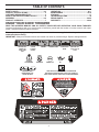
TABLE OF CONTENTS
SAFETY RULES ........................................................ 2-3
PRODUCT SPECIFICATIONS ...................................... 3
CUSTOMER RESPONSIBILITIES................................ 3
SAFETY AND INSTRUCTIONAL DECALS ................. 4
ASSEMBLY ................................................................ 5-6
PRODUCT OVERVIEW ................................................ 7
OPERATION ............................................................ 8-11
MAINTENANCE ..................................................... 12-16
STORAGE ................................................................... 17
TROUBLESHOOTING ................................................ 18
REPAIR PARTS ..................................................... 20-35
WARRANTY........................................................... 36-39
KNOW YOUR SNOW THROWER
READ THIS OWNER'S MANUAL AND ALL SAFETY RULES BEFORE OPERATING YOUR SNOW THROWER.
Compare the illustrations with your snow thrower to familiarize yourself with the location of various controls and adjustments. Save this manual for future reference.
These symbols may appear on your snow thrower or in literature supplied with the product. Learn and
understand their meaning.
IMPORTANT: Safety and instruction decals are located near areas of potential danger. Replace damaged decals.
IGNITION KEY.
INSERT TO
START AND
RUN
CHOKE
CLOSED
(START)
DANGER
OR WARNING
ENGAGING AND
DISENGAGING THE
AUGER BLADES
RECOIL START
PRIMER
ENGINE ON
ENGINE OFF
CHOKE OPEN
(RUN)
OIL
IGNITION KEY.
PULL OUT TO
STOP
FUEL
READ AND FOLLOW ALL SAFETY INFORMATION
AND INSTRUCTIONS BEFORE USE OF THIS PRODUCT.
KEEP THESE INSTRUCTIONS FOR FUTURE REFERENCE.
4
ASSEMBLY
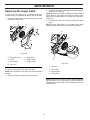
4. Pull up and push down slightly on the handle to verify
handle is locked into place (Figure 4).
NOTE: If handle feels unsecure with the adjustment
levers closed, tighten adjustment handle nuts until the
handle feels secure.
Setup
LOOSE PARTS
Use the chart below to verify that all parts have been
shipped.
Description
5. Remove the cardboard from recoil start handle and
feed the recoil rope through the rope guide.
6. Snap two rotator cables and one wiring harness into
the three cable clips (Figure 5).
Qty.
Carriage bolts
Flange nuts
Washers
Knob
Chute
Deflector
5
3
2
2
1
1
1
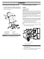
Installing the Handle
1. Remove temporary cable ties holding cables at handle
adjustment holes (Figure 2).
2. Release handle adjustment levers on both sides.
2
3
4
1. Handle
2. Recoil handle
3. Rope guide
4. Adjustment lever nut
1
2
Figure 4
Figure 2
1
1. Cable ties
2. Adjustment lever
2
3. Lift operator handle up to the desired height, and close
adjustment lever ensuring the positioning pin on the
lower handle engages one of the three holes on the
upper handle (Figure 3).
3
Figure 5
1. Rotator cable
2. Wiring harness
3. Cable clip
2
1
Figure 3
1. Positioning pin
2. Upper handle adjustment hole
5
ASSEMBLY
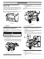
Installing the Discharge Chute
Filling the Engine with Oil
1. Install the chute deflector to the discharge chute using
two screws, washers, and deflector knob (Figure 6).
2. Install the discharge chute to the chute base using
three screws and nuts.
ENGINE
See engine manual.
LUBRICATION
NOTE: Although multi-viscosity oils (5W30, 10W30 etc.)
improve starting in cold weather, these multi-viscosity oils
will result in increased oil consumption when used above
32°F. Check your engine oil level more frequently to avoid
possible engine damage from running low on oil.
Change the oil after every 25 hours of operation or at least
once a year if the snow thrower is not used for 25 hours
in one year.
Check the crankcase oil level before starting the engine
and after each five (5) hours of continuous use. Tighten oil
fill cap / dipstick securely each time you check the oil level.
1. Move the snowthrower to a level surface.
2. Clean around the dipstick (Figure 7).
NOTE: Dipstick location may vary depending on engine
type.
1
2
5
4
5
6
4
3
2
2
3. Remove either side mounted filler cap dipstick or high
oil fill dipstick and wipe it clean.
3
1
Figure 6
1. Chute deflector
2. Carriage bolts
3. Flange nuts
Fill if oil
is below
“Add”
on the
GLSVWLFN
4. Washer
5. Knob
6. Discharge chute
IMPORTANT: Do not overtighten the flange nuts;
otherwise you may damage the discharge chute.
Fill if oil is
below letter
“L” on the
¿OOHUFDS
Figure 7
1. Oil filler cap/dipstick
4. Insert the dipstick into the filler neck and turn clockwise
until fully seated. Then remove the dipstick by turning
it counter-clockwise.
5. Fill oil to "FULL" on dipstick with the recommended oil.
6. Securely screw in the oil filler cap/dipstick.
6
PRODUCT OVERVIEW
Product Overview
10
2
12
1
16
17
3
9
11
4
13
8
*7
*7
6
14
15
5
Figure 8
1.
2.
3.
4.
5.
Discharge chute
Chute deflector
Fuel tank cap
Primer
Electric-start button
(if equipped)
6. Oil drain plug
7. Oil fill cap/dipstick
8. Choke lever
9.
10.
11.
12.
13.
14.
15.
16.
17.
Ignition key
Chute rotator handle
Recoil start handle
Control bar
Lights
Drive side cover
Auger blade
Deflector knob
Owner's Manual
* Dipstick location may vary depending on engine type.
7
OPERATION
Operation
IMPORTANT: Do not use E85 blended fuels. This engine
is not E20/E30/E85 compatible. Alternative fuels with
high alcohol content can cause hard starting, poor engine
performance, and may cause internal engine damage.
NOTE: For best results, purchase only the quantity of
gasoline that you expect to use in 30 days. Otherwise,
you may add fuel stabilizer to newly purchased gasoline
to keep it fresh for up to 6 months.
NOTE: Determine the left and right sides of the machine
from the normal operating position.
• Gasoline is extremely flammable and explosive.
A fire or explosion from gasoline can burn you
and others.
• To prevent a static charge from igniting the gasoline, place the container and/or snowthrower on
the ground before filling, not in a vehicle or on
an object.
• Fill the tank outdoors when the engine is cold.
Wipe up spills.
• Do not handle gasoline when smoking or around
an open flame or sparks.
• Store gasoline in an approved fuel container, out
of the reach of children.
• Do not tip the snowthrower with fuel in the fuel
tank.
Checking the Engine Oil Level
1. Move the snowthrower to a level surface.
2. Clean around the dipstick (Figure 9).
NOTE: Dipstick location may vary depending on engine
type.
3. Remove either side mounted filler cap dipstick or high
oil fill dipstick and wipe it clean.
1
Fill if oil
is below
“Add”
on the
GLSVWLFN
The operation of any snow thrower can result
in foreign objects thrown into the eyes, which
can result in severe eye damage. Always wear
safety glasses or eye shields while operating
your snow thrower or performing any adjustments or repairs. We recommend standard safety glasses
or a wide vision safety mask worn over spectacles.
IMPORTANT: Know how to operate all controls before
adding fuel or attempting to start the engine.
Fill if oil is
below letter
“L” on the
¿OOHUFDS
Filling the Fuel Tank
Fill the fuel tank with fresh, unleaded gasoline (minimum
87 AKI octane rating) (Figure 8).
Figure 9
1. Oil filler cap/dipstick
4. Insert the dipstick into the filler neck and turn clockwise
until fully seated. Then remove the dipstick by turning
it counter-clockwise.
5. Fill oil to "FULL" on dipstick with the recommended oil.
6. Securely screw in the oil filler cap/dipstick.
NOTE: Running the engine with a low oil level can cause
engine damage. Always check the engine oil before start up.
NOTE: Running the engine with too much oil may cause
engine damage and excess smoke in the exhaust. Always
check the engine oil level before start up.
Figure 8
IMPORTANT: Do not add oil to the gasoline.
8
OPERATION
Starting the Engine
1. Push key in (Figure 10).
2. Move choke lever to left position.
3. Firmly push in the primer 2 times with your thumb,
holding the primer in a for a second before releasing
it each time.
NOTE: Remove your glove when you push in the primer
so that air cannot escape from the primer hole.
IMPORTANT: It may not be necessary to use the primer
or the choke if the engine has been running and is hot.
Excessive priming may flood the engine and prevent it
from starting.
1
1
3
2
Figure 12
1. Electric start button
NOTE: Use an extension cord recommended for outdoor
use that is not longer than 50 feet (15 m).
Figure 10
The electrical cord can become damaged, causing
a shock or fire.
Thoroughly inspect the electrical cord before plugging it into a power source. If the cord is damaged,
do not use it to start the snowthrower. Replace or
repair the damaged cord immediately. Contact an
Authorized Service Dealer for assistance.
1. Key
2. Choke lever
3. Primer
4. Pull the recoil starter (Figure 11) or if your snow thrower
is equipped with an electric starter, connect an extension cord to the snow thrower and plug the other end
into a three-hole grounded 110 volt A.C. receptacle
and push the electric-start button (Figure 12).
IMPORTANT: Run the electric starter no more than 10
times at intervals of 5 seconds on, then 5 seconds off.
Running the electric starter extensively can overheat and
damage it. If the engine does not start after this series of
attempts, wait at least 40 minutes to allow the starter to
cool before attempting to start it again. If the engine does
not start after the second series of attempts, take the
snowthrower to an Authorized Service Dealer for service.
NOTE: If you pull the recoil handle and feel no resistance,
the starter may be frozen. Thaw out the starter before
attempting to start the snowthrower.
5. While the engine is running, move the choke lever
slowly to the right position.
6. Unplug the extension cord from the power source and
the snowthrower (Figure 12).
1
Unplug the power cord whenever you are not starting the snowthrower.
Figure 11
1. Recoil start handle
9
OPERATION
Engaging the Auger Blades
1. To engage the auger blades, hold the control bar against
the handle (Figure 13).
1
1
2
Figure 15
1. Rub Area
2. Wear Areas
Stopping the Engine
Figure 13
1. Control bar
1. To stop the engine, pull key out (Figure 16).
1
Disengaging the Auger Blades
1. To disengage the auger blades, release the control bar
(Figure 14).
1
1. Key
Figure 16
Adjusting the Discharge
Chute and Chute Deflector
1. To adjust the discharge chute, rotate chute handle left
or right to desired position (Figure 17).
Figure 14
1. Control bar
IMPORTANT: During initial operation there may be wear
between the auger blades and the scraper bar. Maximum
performance, both snow throwing and driving, occurs
when there is zero clearance between these two parts
(Figure 15).
During initial break-in period of the auger blades it
is normal for the auger blades to build up excessive
heat if not operated in the snow.
Do not operate without snow or water for lubricating
the auger blades. This will cause excessive heat
build up in the auger blades which could cause
damage to the auger blades and scraper bar.
1
1. Chute rotator handle
Figure 17
10
OPERATION
Preventing Freeze-up After Use
2. To raise or lower the angle of the chute deflector, loosen
both chute deflector knobs on the chute deflector and
move the chute deflector up or down to desired position
and retighten knobs (Figure 18).
•
1
•
•
2
•
•
2
Let the engine run for a few minutes to prevent moving
parts from freezing. Stop the engine, wait for all moving parts to stop, and remove ice and snow from the
snowthrower.
Clean off any snow and ice from the base of the chute.
Rotate the discharge chute left and right to free it from
any ice buildup.
With the ignition key in the Off position, pull the recoil
starter handle several times or connect the electrical
cord to a power source and the snowthrower and push
the electric start button once to prevent the recoil starter
and/or the electric starter from freezing up.
In snowy and cold conditions, some controls and moving parts may freeze. Do not use excessive force when
trying to operate frozen controls. If you have difficulty
operating any control or part, start the engine and let
it run for a few minutes.
Operating Tips
1. Chute deflector
2. Chute deflector knobs
Figure 18
The auger blades can throw stones, toys, and
other foreign objects and cause serious personal
injury to the operator or to bystanders.
• Keep the area to be cleared free of all objects
that the auger blades could pick up and throw.
• Keep all children and pets away from the area
of operation.
• Do not operate snow thrower if weather conditions impair visibility. Throwing snow during
a heavy, windy snowstorm can blind you and
be hazardous to the safe operation of the snow
thrower.
Clearing a Clogged Discharge
Chute
Hand contact with the rotating auger blades
inside the discharge chute is the most common
cause of injury associated with snow throwers.
Never use your hand to clean out the discharge
chute.
To clear the chute:
1. SHUT THE ENGINE OFF!
2. Wait 10 seconds to be sure the auger blades have
stopped rotating.
3. Always use a clearing tool at least 15 inches long, not
your hands (Figure 19).
•
•
•
•
•
•
•
•
Figure 19
11
The best time to remove snow is the early morning.
At this time the snow is usually dry and has not been
exposed to the direct sun and warming temperatures.
Slightly overlap each successive path to ensure all
snow will be removed.
Throw snow downwind whenever possible.
For extremely heavy snow, reduce the width of snow
removal by overlapping previous path and moving
slowly.
Keep engine clean and clear of snow during use. This
will help air flow and extend engine life.
After snow-throwing is completed, allow engine to run
for a few minutes to melt snow and ice off the engine.
Clean the entire snow thrower thoroughly after each
use and wipe dry so it is ready for next use.
Spraying off unit with a hose is NOT recommended.
MAINTENANCE
Maintenance
NOTE: Determine the left and right sides of the machine from the normal operating position.
Check for Loose Fasteners
Clean / Inspect Snow Thrower
Clean / Replace V-Belts
Check / Replace Auger Blades and Scraper Bar
Check Fuel Lines and Electrical Wires
Check Engine Oil Level
Change Engine Oil
Inspect Muffler
Check / Replace Spark Plug
Empty Fuel Tank
NOTE: You may need to adjust the control cable from
position 1 (default) to position 2 if you notice belt slip
when the control bar is engaged.
Adjusting the Control Cable
CHECKING THE CONTROL CABLE
NOTE: If the control cable is adjusted to position 2,
ensure that the auger stops properly when the control bar
is released
1. Release the control bar to remove the slack in the
control cable (Figure 20).
ADJUSTING THE CONTROL CABLE
1. With the control bar disengaged, unhook and move
the control cable to the highest position. (Figure 21).
1
2
1
Position 2
3
Figure 20
1. Control bar
Position 1:
Default position
(Lower Hole as
shown in illustration)
IMPORTANT: The control cable must contain some slack
when you disengage the control bar for the auger blades
to stop properly.
Figure 21
1. Control bar
2. Adjuster link
3. Cable positions
12
MAINTENANCE
Inspecting the Auger Blades/
Scraper Bar
5. After draining the used oil, return the snowthrower to
the operating position.
6. Install the oil drain plug and torque to 145-150 in-lbs
(17 N-m).
NOTE: Dipstick location may vary depending on engine
type.
Before each session, inspect the auger blades for wear.
When an auger blade edge or the scraper bar has worn
down have an Authorized Service Dealer replace the
auger blades and the scraper bar (Figure 22).
NOTE: Auger blades and scraper bar are wear items and
may have to be replaced after extended use.
1
1
2
Figure 22
Figure 24
1. Auger blades
2. Scraper bar
1. Oil fill cap/dipstick
7. Clean around the oil filler cap/dipstick (Figure 24).
8. Unscrew the oil fill cap/dipstick and remove it
(Figure 25).
9. With the snowthrower in the operating position, carefully pour oil into the oil fill hole until "Full" on the fill
cap/dipstick line (Figure 25).
Max fill: 18 oz. (0.5 l), type: automotive detergent oil
with an API service classification of SJ, SL, or higher.
Changing the Engine Oil
Run the engine a few minutes before changing the
oil to warm it. Warm oil flows better and carries more
contaminants.
The engine oil will be hot. Avoid skin contact
with the used engine oil.
1.
2.
3.
4.
Move snowthrower to a level surface.
Run snowthrower until all fuel has been depleted.
Remove ignition key.
Place an oil drain pan under the oil drain plug, remove
the oil drain plug, and tip the snowthrower backward
and drain the used oil in the oil drain pan (Figure 23).
Fill if oil
is below
“Add”
on the
GLSVWLFN
Fill if oil is
below letter
“L” on the
¿OOHUFDS
Figure 25
1
10. Screw in the oil fill cap/dipstick and hand tighten it
securely.
11. Wipe up any spilled oil.
12. Dispose of the used oil properly at a local recycling
center.
Figure 23
1. Oil drain plug
13
MAINTENANCE
8. Unsnap top cover by firmly pulling upwards at the
rear section of the cover disengaging the three clips
(Figure 28).
9. Shift top cover until fuel tank is clear of the rear upper
cover and set top cover to the side of the unit.
10. Temporarily reinstall oil fill cap to prevent foreign object
from entering the engine.
11. Remove 2 screws in the side cover and rear covers
on both sides.
Servicing the Spark Plug
Use a NGK BPR6ES, Champion RN9YC, or BOSCH
WR6DC spark plug or equivalent.
1.
2.
3.
4.
5.
Move snow thrower to a level surface.
Run snow thrower until all fuel has been depleted.
Wait until engine is cool.
Rotate the discharge chute so that it faces forward.
Remove the discharge chute by removing the three
carriage bolts and three flange nuts (Figure 26).
2
3
1
4
1
3
3
3
2
3
2
Figure 28
1. Top cover
2. Clips
Figure 26
1. Discharge chute
2. Carriage bolts
3. Flange nuts
3. Screw
4. Rear upper cover
12. Unplug electrical wires on back of ignition switch
(Figure 29).
13. Pull tube off the back of the primer bulb.
6. Remove two screws in plenum that hold top cover
(Figure 27).
7. Remove the oil fill cap.
2
2
4
2
4
3
1
1
4
3
Figure 29
1. Electrical wires
2. Ignition switch
Figure 27
1. Screw
2. Plenum
3. Tube
4. Primer bulb
14. Lift rear upper cover and lay it to the side of the unit.
IMPORTANT: The recoil rope will still be attached to the
upper cover.
3. Oil fill cap
4. Top cover
14
MAINTENANCE
19. Install the spark plug and torque it to 20–22 ft-lb
(27–30 N-m).
20. Connect the spark plug wire to the spark plug
(Figure 30).
21. Reattach primer bulb tube to primer bulb and electrical wires on back ignition switch of rear upper cover
(Figure 29).
22. Set rear upper cover in place so the two screw holes
line up with the rear lower cover and side covers
(Figure 32).
23. Reattach two screws through the rear covers and into
the clip on the side cover (Figure 27).
15. Disconnect the spark plug wire from the spark plug
(Figure 30).
16. Clean around the spark plug.
17. Remove the spark plug from the cylinder head.
1
Figure 30
1. Spark plug wire
IMPORTANT: Replace a cracked, fouled, or dirty spark
plug. Do not clean the electrodes because grit entering
the cylinder can damage the engine.
18. Set the gap on the plug to 0.030 inch (0.76 mm)
(Figure 31).
0.030 inch
(0.76 mm)
Figure 32
24. Remove top oil fill cap.
25. Set top cover in place and snap three top cover clips
into the rear upper cover (Figure 28).
26. Reinstall top oil fill cap.
27. Reinstall two screws in the side covers that attach to
the clips on the top cover.
28. Reinstall two screws in the plenum that attach to the
top cover (Figure 27).
29. Reinstall discharge chute with the hardware removed
in step 5.
Figure 31
15
MAINTENANCE
4. Install the new auger v-belt and drive pulley, routing it
as shown in (Figure 34).
NOTE: Route the new auger v-belt first around the engine
pulley, then the idler pulley, and finally around the drive
pulley while pressing down on the front of the idler arm.
(Figure 33).
Replacing the Auger V-Belt
If auger v-belt becomes worn, oil-soaked, excessively
cracked, frayed, or otherwise damaged, replace the belt.
1. Remove the drive side cover by removing the six screws
as shown in (Figure 33).
4
5. Install the drive side cover with the screws removed in
step 1.
NOTE: Ensure belt keeper on the plastic side panel
engages between belt and frame before bolting down.
5
6
7
2
1
2
3
1
3
2
Figure 33
1.
2.
3.
4.
Drive side cover
Screw
Drive pulley
Idler arm
5. Idler pulley
6. Engine pulley
7. Auger V-Belt
4
Figure 34
1.
2.
3.
4.
2. Remove drive pulley from the auger shaft.
NOTE: Nut is welded to drive pulley and has left handed
threads.
Idler arm
Idler pulley
Engine pulley
Drive pulley
3. Remove the auger v-belt from the drive pulley.
NOTE: Ensure that the auger v-belt is properly adjusted
and operating; refer to Checking the Control Cable and
Adjusting the Control Cable in the Maintenance section
of this manual.
16
STORAGE
Storage
ENGINE OIL
Drain oil (with engine warm) and replace with clean engine
oil. (See “Changing the Engine Oil” section of this manual).
STORING THE SNOWTHROWER
Immediately prepare your snow thrower for storage at
the end of the season or if the unit will not be used for 30
days or more.
CYLINDER
1. Remove spark plug.
2. Pour one ounce (29 ml) of oil through spark plug hole
into cylinder.
3. Pull recoil starter handle slowly a few times to distribute
oil.
WARNING: Never store the snow thrower with
gasoline in the tank inside a building where fumes
may reach an open flame, spark or pilot light as
on a furnace, water heater, clothes dryer or gas
appliance. Allow the engine to cool before storing
in any enclosure.
OTHER
•
•
•
Remove safety ignition key; store it in a safe place.
Do not store gasoline from one season to another.
Replace your gasoline can if your can starts to rust.
Rust and/or dirt in your gasoline will cause problems.
• If possible, store your snow thrower indoors and cover
it to protect it from dust and dirt.
• Cover your snow thrower with a suitable protective
cover that does not retain moisture. Do not use plastic.
Plastic cannot breathe, which allows condensation to
form and will cause your snow thrower to rust.
IMPORTANT: Never cover snow thrower while engine/
exhaust area is still warm.
SNOW THROWER
When snow thrower is to be stored for a period of time,
clean it thoroughly, remove all dirt, grease, leaves, etc.
Store in a clean, dry area.
1. Clean entire snow thrower after each use.
2. Inspect and replace belts, if necessary (See “Replaceing the Drive Belt” section of this manual).
3. Be sure that all nuts, bolts, screws, and pins are securely
fastened. Inspect moving parts for damage, breakage
and wear. Replace if necessary.
FUEL SYSTEM
IMPORTANT: It is important to prevent gum deposits from
forming in essential fuel system parts such as carburetor,
fuel hose, or tank during storage. Also, alcohol blended
fuels can attract moisture which leads to separation and
formation of acids during storage. Acidic gas can damage
the fuel system of an engine while in storage.
• Empty the fuel tank by starting the engine and letting
it run until the fuel lines and carburetor are empty.
• Never use engine or carburetor cleaner products in
the fuel tank or permanent damage may occur.
• Use fresh fuel next season.
NOTE: Fuel stabilizer is an acceptable alternative in minimizing the formation of fuel gum deposits during storage.
Add stabilizer to gasoline in fuel tank or storage container.
Always follow the mix ratio found on stabilizer container.
Run engine at least 10 minutes after adding stabilizer to
allow the stabilizer to reach the carburetor. Do not empty
the gas tank and carburetor if using fuel stabilizer.
17
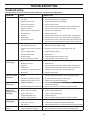
TROUBLESHOOTING
Troubleshooting
See appropriate section in manual unless directed to a service center/department.
PROBLEM
CAUSE
CORRECTION
Does not start
1. Safety ignition key is not inserted.
1. Insert safety ignition key.
2. Out of fuel.
2. Fill fuel tank with fresh, clean gasoline.
3. ON/OFF switch is OFF.
3. Move ON/OFF switch to ON position.
4. Choke in OFF position.
4. Move to FULL position.
Loss of power
5. Primer not depressed.
5. Prime as instructed in the Operation section of this manual.
6. Engine is flooded.
6. Wait a few minutes before restarting, DO NOT prime.
7. Spark plug wire is disconnected.
7. Connect wire to spark plug.
8. Bad spark plug.
8. Replace spark plug.
9. Stale fuel.
9. Empty fuel tank & carburetor, refill with fresh, clean gasoline.
10. Water in fuel.
10. Empty fuel tank & carburetor, refill with fresh, clean gasoline.
11. Vapor locked fuel line.
11. Ensure all the fuel line is below the outlet of the fuel tank. Fuel
line should run continuously down from fuel tank to carburetor.
1. Spark plug wire loose.
1. Reconnect spark plug wire.
2. Throwing too much snow.
2. Reduce speed and width of swath.
3. Fuel tank cap is covered with ice or 3. Remove ice and snow on and around fuel tank cap.
snow.
Engine idles or
runs roughly
Excessive
vibration / Handle
movement
Recoil starter is
hard to pull
4. Dirty or clogged muffler.
4. Clean or replace muffler.
5. Improper cable length.
5. Adjust cable.
6. Blocked muffler.
6. Clear blockage (ensure engine is cool).
7. Blocked carburetor air intake.
7. Clear blockage (ensure engine is cool).
1. Choke is in FULL position.
1. Move choke to OFF position.
2. Blockage in fuel line.
2. Clean fuel line.
3. Stale fuel.
3. Empty fuel tank & carburetor, refill with fresh, clean gasoline.
4. Water in fuel.
4. Empty fuel tank & carburetor, refill with fresh, clean gasoline.
5. Carburetor is in need of replacing
5. Contact an authorized service center/department.
6. Belt stretch.
6. Replace auger v-belt.
1. Loose parts or damaged augers or
impeller.
1. Tighten all fasteners. Replace damaged parts. If vibration
remains, contact an authorized service center/department.
2. Handles not positioned correctly.
2. Ensure handles are locked into positioning.
3. Adjustment lever nuts are loose.
3. Tighten nuts until handle feels secure.
1. Frozen recoil starter.
1. See “IF RECOIL STARTER HAS FROZEN” in the Operation
section of this manual.
2. Rope is interfering with components. 2. Recoil rope should not be touching any wires or hoses.
Loss of snow
discharge or
slowing of snow
discharge
Lights not On
(If Equipped)
Rotator hard to
move
1. Worn belt.
1. Adjust drive cable per maintenance procedures.
2. Auger v-belt is off of pulley.
2. Check / reinstall auger v-belt.
3. Auger v-belt is worn.
3. Check / replace auger v-belt.
4. Clogged discharge chute.
4. Clean snow chute.
5. Augers / impeller jammed.
5. Remove debris or foreign object from augers / impeller.
1. Motor not running.
1. Start engine.
2. Loose wire connection.
2. Check wire connections at engine and both lights.
3. LED burnt out.
3. Replace LED light module. (Individual LEDs are not replaceable)
1. Debris in chute rotator mechanism. 1. Clean internal parts of chute rotator mechanism.
2. Cable are kinked or damaged.
2. Ensure cables are not kinked. Replace damaged cables.
18
SERVICE NOTES
19
REPAIR PARTS SNOW THROWER - - MODEL NUMBER ST 121E (96183000100)
HANDLE ASSEMBLY
1
2
20
3
20
21
4
20
5
19
9
10
7
8
12
15
14
14
17
12
13
7
15
16
11
16
18
17
NOTE: All component dimensions given in U.S. inches. 1 inch = 25.4 mm
IMPORTANT: Use only Original Equipment Manufacturer (O.E.M.) replacement parts.
Failure to do so could be hazardous, damage your snow thrower and void your warranty.
20
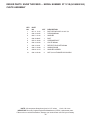
REPAIR PARTS SNOW THROWER - - MODEL NUMBER ST 121E (96183000100)
HANDLE ASSEMBLY
KEY
NO.
PART
NO.
QTY
DESCRIPTION
1
532 44 32-45
1
SUBASM.CONTROL.SHROUD
2
532 44 16-24
1
COVER.HANDLE.LG.SHROUD
3
532 44 33-18
1
BRACKET.SUPPORT - DCC - STAMP - BLK
4
532 44 27-75
1
SUBASM.RH.LED
5
532 44 27-76
1
SUBASM.LH.LED
6
532 44 34-33
1
BAIL.OVERMOLD.ASM
7
532 44 22-50
4
SCREW.PAN.HD.TORX 1/4-20 X .750
8
532 14 50-06
3
CLIP.PUSH-IN.HINGED
9
532 43 75-06
1
DECAL.HANDLE BAR.AUGER INST
10
532 44 34-32
1
HANDLE.UPPER.ERGO.MS498
11
532 44 30-18
1
CABLE.CLUTCH.SSST.SHORT
12
817 41 13-18
4
HEX.WASHER.HEAD 13-16 X 1.125
13
532 13 20-04
1
HEX.NUT.1/4-20.NYLON.LOCKING
14
532 44 22-48
4
NUT.5/16-18.FLANGE.NYLOCK.BLK
15
532 85 10-74
2
WASHER.HARD
16
532 18 88-21
2
BOLT.HANDLE.ADJ
17
532 44 30-21
2
SUBASM.QUICK.ADJUST.COLD
18
532 44 22-34
1
GUIDE.ROPE
19
532 44 30-46
1
HARNESS.LED
20
817 41 13-12
8
BOLT.HEX.WSH 13-16 X 3/4
21
819 09 10-16
4
WASHER.9/32 X 5/8 X 16 GA
NOTE: All component dimensions given in U.S. inches. 1 inch = 25.4 mm
IMPORTANT: Use only Original Equipment Manufacturer (O.E.M.) replacement parts.
Failure to do so could be hazardous, damage your snow thrower and void your warranty.
21
REPAIR PARTS SNOW THROWER - - MODEL NUMBER ST 121E (96183000100)
CHUTE ASSEMBLY
7
8
9
9
8
10
6
10
10
5
4
3
5
2
1
NOTE: All component dimensions given in U.S. inches. 1 inch = 25.4 mm
IMPORTANT: Use only Original Equipment Manufacturer (O.E.M.) replacement parts.
Failure to do so could be hazardous, damage your snow thrower and void your warranty.
22
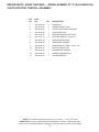
REPAIR PARTS SNOW THROWER - - MODEL NUMBER ST 121E (96183000100)
CHUTE ASSEMBLY
KEY
NO.
1
PART
NO.
817 41 13-12
QTY
2
DESCRIPTION
BOLT.HEX.WSH.HD.13-16 X 3/4
2
532 44 34-25
1
PLENUM.MS498
3
819 13 13-16
1
WASHER
4
532 42 88-67
1
BOLT
5
872 01 05-06
5
CARRIAGE.BOLT
6
532 44 34-30
1
CHUTE.MS498
7
532 44 34-31
1
DEFLECTOR.CHUTE.MS498
8
532 19 19-38
2
HANDLE.KNOB
9
532 85 10-74
2
WASHER.HARDEN
10
532 44 22-48
3
NUT.5/16-18.FLANGE.NYLOCK.BLK
NOTE: All component dimensions given in U.S. inches. 1 inch = 25.4 mm
IMPORTANT: Use only Original Equipment Manufacturer (O.E.M.) replacement parts.
Failure to do so could be hazardous, damage your snow thrower and void your warranty.
23
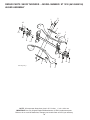
REPAIR PARTS SNOW THROWER - - MODEL NUMBER ST 121E (96183000100)
CHUTE ROTATOR CONTROL ASSEMBLY
13
12
11
5
10
9
6
2
2
10
9
2
2
6
4
5
8
7
3
1
NOTE: All component dimensions given in U.S. inches. 1 inch = 25.4 mm
IMPORTANT: Use only Original Equipment Manufacturer (O.E.M.) replacement parts.
Failure to do so could be hazardous, damage your snow thrower and void your warranty.
24
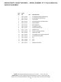
REPAIR PARTS SNOW THROWER - - MODEL NUMBER ST 121E (96183000100)
CHUTE ROTATOR CONTROL ASSEMBLY
KEY
NO.
PART
NO.
QTY
DESCRIPTION
1
532 43 68-05
2
CABLE.DCC
2
532 43 68-06
4
CABLE.BRACKET_DCC
3
532 43 48-75
1
PLATE.CHUTE.BASE.PNT.MS431
4
532 44 39-39
1
CHUTE.BASE.DCC
5
532 44 39-38
2
RING.RETAINING.CHUTE.SSST
6
817 41 13-12
5
BOLT.HEX.WSH.HD.13-16 X 3/4
7
532 43 48-78
1
ARM.CHUTE.RATCHET
8
532 40 65-58
1
SPRING.RETURN.RGD
9
532 44 22-50
4
SCREW.PAN.HD.TORX 1/4-20 X .750
10
532 43 54-17
1
NUT.PUSH.AXLE.0.5IN
11
532 44 28-35
1
GRIP.HANDLE.SUBASM
12
532 43 68-90
1
HANDLE.SUBASM.PIVOT
13
532 44 39-40
1
PULLEY.RING.DCC
NOTE: All component dimensions given in U.S. inches. 1 inch = 25.4 mm
IMPORTANT: Use only Original Equipment Manufacturer (O.E.M.) replacement parts.
Failure to do so could be hazardous, damage your snow thrower and void your warranty.
25
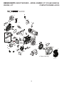
REPAIR PARTS SNOW THROWER - - MODEL NUMBER ST 121E (96183000100)
SHROUD ASSEMBLY
5
14
6
17
10
7
15
1
10
10
13
15
10
4
10
2
16
10
16
3
10
9
8
16
9
10
10
10
12
11
NOTE: All component dimensions given in U.S. inches. 1 inch = 25.4 mm
IMPORTANT: Use only Original Equipment Manufacturer (O.E.M.) replacement parts.
Failure to do so could be hazardous, damage your snow thrower and void your warranty.
26
REPAIR PARTS SNOW THROWER - - MODEL NUMBER ST 121E (96183000100)
SHROUD ASSEMBLY
KEY
NO.
PART
NO.
QTY
DESCRIPTION
1
532 44 34-26
1
COVER.NON-DRIVE.SIDE.MS428
2
532 44 39-73
1
COVER.DRIVE.SIDE.MS428
3
532 44 34-28
1
TOP.COVER
4
532 43 02-20
1
CAP.ASM.FUEL.2.25"FR.N/CB.E10
5
532 43 62-35
1
BULB.PRIMER
6
532 43 54-07
1
KEY HOUSING
7
532 44 34-29
1
TOP.REAR.COVER
8
532 43 76-31
1
PLATE.EXHAUST.PNT.
9
817 41 13-12
2
SCREW.HI-LO
10
532 44 22-50
12
TORX.1/4-20X3/4.SCREW
11
532 43 48-80
1
TANK.FUEL.ASM
12
532 14 68-48
2
TIE.CABLE.24.5X.29.NYLON.WHITE
13
532 44 34-24
1
COVER.REAR.LOWER
14
532 44 30-69
2
KEY
15
532 43 48-68
3
CLIP
16
532 19 66-88
3
CLIP
17
532 44 30-70
1
HANDLE.STARTER
NOTE: All component dimensions given in U.S. inches. 1 inch = 25.4 mm
IMPORTANT: Use only Original Equipment Manufacturer (O.E.M.) replacement parts.
Failure to do so could be hazardous, damage your snow thrower and void your warranty.
27
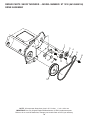
REPAIR PARTS SNOW THROWER - - MODEL NUMBER ST 121E (96183000100)
DRIVE ASSEMBLY
1
3
4
2
8
6
7
11
10
5
9
10
12
NOTE: All component dimensions given in U.S. inches. 1 inch = 25.4 mm
IMPORTANT: Use only Original Equipment Manufacturer (O.E.M.) replacement parts.
Failure to do so could be hazardous, damage your snow thrower and void your warranty.
28
REPAIR PARTS SNOW THROWER - - MODEL NUMBER ST 121E (96183000100)
DRIVE ASSEMBLY
KEY
NO.
1
PART
NO.
532 43 48-60
QTY
1
DESCRIPTION
SPACER.ENGINE.CRANK
2
532 43 45-02
1
KEEPER.ENGINE.BELT
3
532 42 64-90
1
PULLEY.ENG.TRACTION.3/4
4
532 85 10-74
1
WASHER.HARDEN
5
532 43 72-61
1
BELT-V.TRACTION
6
532 43 08-17
1
SCREW.CAP.SCHD.3/8-24 X 1.25
7
532 43 48-59
1
SPRING.IDLER.PULLEY.RETURN
8
532 43 76-09
1
ARM.IDLER.PNT.MS431
9
532 16 60-43
1
PULLEY.IDLER.BACKSIDE
10
817 06 06-20
2
SCREW.3/8-16 X 1.SMGML.TAP/R.BLK
11
532 19 90-92
1
SPACER.RETAINER
12
532 43 53-83
1
PULLEY.DRIVEN
NOTE: All component dimensions given in U.S. inches. 1 inch = 25.4 mm
IMPORTANT: Use only Original Equipment Manufacturer (O.E.M.) replacement parts.
Failure to do so could be hazardous, damage your snow thrower and void your warranty.
29
REPAIR PARTS SNOW THROWER - - MODEL NUMBER ST 121E (96183000100)
FRAME ASSEMBLY
11
1
2
3
4
15
14
15
10
8
8
5
3
4
8
9
6
6
12
7
13
12
7
12
7
NOTE: All component dimensions given in U.S. inches. 1 inch = 25.4 mm
IMPORTANT: Use only Original Equipment Manufacturer (O.E.M.) replacement parts.
Failure to do so could be hazardous, damage your snow thrower and void your warranty.
30
REPAIR PARTS SNOW THROWER - - MODEL NUMBER ST 121E (96183000100)
FRAME ASSEMBLY
KEY
NO.
PART
NO.
QTY
DESCRIPTION
1
532 44 21-59
1
ENGINE.208.LCT.ESTRT.W/ALT
2
532 44 47-23
1
FRAME.WELDMENT.SSST
3
532 44 28-25
2
WHEEL.HUSQVARNA
4
532 43 54-17
2
NUT.PUSH.AXLE.0.5IN
5
532 43 55-78
2
SCREW.5/16-24 X 2.00"HHCS
6
532 15 04-06
2
BOLT.ENG. 3/8-16 X 1.280
7
532 19 17-30
3
NUT.HEX.FLANGE.1/4-20.CTR.LOCK
8
872 11 04-07
3
BOLT.RDHD.SQNK.1/4-20 UNC X 7/8
9
532 44 29-42
1
BAR.SCRAPPER.HDPE
10
532 43 48-57
2
SPACER.ENGINE
11
532 43 48-74
1
LEVER.CHOKE
12
819 09 10-16
3
WASHER.9/32 X 5/8 X 16 GA.
13
532 44 21-46
1
SKIRT.SCRAPPER.SSST
14
532 44 34-23
1
SUPPORT.SSST.REAR.FRAME
15
532 44 22-50
4
TORX.1/4-20 X 3/4.SCREW
NOTE: All component dimensions given in U.S. inches. 1 inch = 25.4 mm
IMPORTANT: Use only Original Equipment Manufacturer (O.E.M.) replacement parts.
Failure to do so could be hazardous, damage your snow thrower and void your warranty.
31
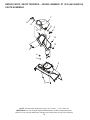
REPAIR PARTS SNOW THROWER - - MODEL NUMBER ST 121E (96183000100)
AUGER ASSEMBLY
2
3
1
10
11
4
14
7
56
13
9
1
12
8
9
11
12
5
4
5
13
6
10
11
SSST-Auger asm_1
7
1
NOTE: All component dimensions given in U.S. inches. 1 inch = 25.4 mm
IMPORTANT: Use only Original Equipment Manufacturer (O.E.M.) replacement parts.
Failure to do so could be hazardous, damage your snow thrower and void your warranty.
32
REPAIR PARTS SNOW THROWER - - MODEL NUMBER ST 121E (96183000100)
AUGER ASSEMBLY
KEY
NO.
1
PART
NO.
872 11 04-07
2
532 43 76-20
1
PIN.ROLL.3/16 X 1-1/4
3
532 19 96-87
1
BOLT.1/4-20.1.50"
4
532 43 76-18
2
PLATE.CENTER.BLADE
5
532 13 20-04
13
HEX.NUT.1/4-20 NYLON LOCKING
6
819 09 10-16
8
WASHER 9/32 X 5/8 X 16 GA.
7
532 44 27-59
2
BLADE.AUGER
8
532 43 76-17
1
WELDMENT.AUGER.ASM
9
532 43 76-21
2
SUPPORT.BEARING.SSST.PNT
10
532 43 76-22
2
BEARING.BALL.MANDREL
11
817 60 04-06
4
SCREW.HEX.WASHEAD.1/4-20 X 3/8
12
872 11 04-04
2
BOLT.CARR.SS.1/4-20 UNC X 1/2.GR5
13
532 43 81-30
2
WHIZ.LOCK.NUTS.BEARING CAPS
14
812 00 00-28
1
RETAINING.CLIP
QTY
12
DESCRIPTION
BOLT.CARRIAGE
NOTE: All component dimensions given in U.S. inches. 1 inch = 25.4 mm
IMPORTANT: Use only Original Equipment Manufacturer (O.E.M.) replacement parts.
Failure to do so could be hazardous, damage your snow thrower and void your warranty.
33
REPAIR PARTS SNOW THROWER - - MODEL NUMBER ST 121E (96183000100)
ENGINE, LCT
COMPLETE ENGINE-442159
442159
56
37
36
27
57
34
49
30
31
29
62
47
38
39
10 10A
44
22A
22
53*
52*
40
41
32
*Included
with part# 40
50
23
21
65
26 26A
20 20A
48
28
46
11
19
18
6
8
46A
3
Electric Start Only
17
rev. 6/8/11
34
REPAIR PARTS SNOW THROWER - - MODEL NUMBER ST 121E (96183000100)
ENGINE, LCT
COMPLETE ENGINE-442159
KEY
NO.
PART
NO.
3
6
8
444277
437122
437123
10
10A
437124
437125
11
17
424954
436967
18
19
436968
443899
20
424971
20A
429230
21
22
424973
424975
22A
429596
23
26
420580
429235
26A
420585
DESCRIPTION
MUFFLER ASSEMBLY-SNOW
SNOW CARBURETOR ASSY
FUEL PRIMER BULB WITH
HOSE
ELECTRIC STARTER ASSY
EUROPEAN 230V ELECTRIC
STARTER
KEY SWITCH ASSY
RECOIL STARTER
ASSEMBLY-SNOW
STARTER CUP SMALL
SNOW STARTER GRIP
(DELUXE)
BLOWER HOUSING ASSEMBLY
ELECTRIC START - SNOW
(BLACK)
BLOWER HOUSING ASSEMBLY
MANUAL START - SNOW
(BLACK)
SHIELD, CYLINDER
SHIELD, FLYWHEEL ELECTRIC START
(IF EQUIPPED)
SHIELD, FLYWHEEL MANUAL START
VALVE COVER
ELECTRIC START FLYWHEEL
ASSY
MANUAL START FLYWHEEL
ASSY
35
KEY
NO.
PART
NO.
27
28
29
30
31
32
34
36
37
38
39
40
41
44
46
46A
47
48
49
50
52
53
54
56
57
62
65
444091
420586
443894
420606
420961
444090
436966
420601
420602
429646
420584
420578
424939
420582
429260
444275
429599
437967
429600
429259
429691
420579
436567
429601
438014
435495
435495
DESCRIPTION
HIGH OIL FILL TUBE ASSY
FLYWHEEL FAN
IGNITION COIL ASSY (HI-TEMP)
CRANKCASE COVER ASSY
BLACK OIL DIPSTICK
CHARGING COIL (18 WATT)
SPARK PLUG BOOT
GOVERNOR ARM ASSY
GOVERNOR SHAFT
GOVERNOR GEAR ASSY
CAMSHAFT
CYLINDER HEAD ASSY
SPARK PLUG
PISTON AND ROD ASSY
VAPOR SHIELD
INTAKE SHIELD
SEAL KIT
WIRE HARNESS
CRANKSHAFT
SPEED CONTROL BRACKET
ROCKER ARM KIT
PUSH ROD KIT
CYLINDER ASSEMBLY
GASKET KIT
FUEL HOSE KIT
NON-REMOVABLE OIL PLUG
OIL DRAIN PLUG KIT
&RQVXPHU:KHHOHG3URGXFWV±/LPLWHG:DUUDQW\
+XVTYDUQDZDUUDQWVWRWKHRULJLQDOUHWDLOSXUFKDVHUWKDWWKLV+XVTYDUQDSURGXFWLVIUHHIURPGHIHFWVLQPDWHULDORUZRUNPDQVKLS
XQGHUQRUPDOXVHDQGPDLQWHQDQFHIURPWKHGDWHRIUHWDLOSXUFKDVHIRUWKHDSSOLFDEOH:DUUDQW\3HULRGVKRZQRQ([KLELW$&HUWDLQ
FRPSRQHQWVHJHQJLQHVDQGWUDQVPLVVLRQVDUHH[FOXGHGIURPFRYHUDJHDQGRWKHUOLPLWDWLRQVDSSO\DVGHVFULEHGLQWKLVGRFXPHQW
+XVTYDUQDZLOOUHSDLURUUHSODFHDWLWVGLVFUHWLRQDQ\GHIHFWLYHSURGXFWRUSDUWFRYHUHGE\WKH/LPLWHG:DUUDQW\IUHHRIFKDUJHDWDQ\
DXWKRUL]HG +XVTYDUQD 6HUYLFLQJ 'HDOHU&HQWHU XVLQJ RULJLQDO 2(0 +XVTYDUQD UHSODFHPHQW SDUWV VXEMHFW WR WKH OLPLWDWLRQV DQG
H[FOXVLRQVGHVFULEHGEHORZ+XVTYDUQDGRHVQRWRIIHUDQRYHUWKHFRXQWHUH[FKDQJHSURJUDP
7+,6 /,0,7(' :$55$17< ,6 7+( 62/( (;35(66 :$55$17< 3529,'(' %< +8649$51$ $1< :$55$17<
7+$7 0$< %( ,03/,(' %< /$: ,1&/8',1* $1< ,03/,(' :$55$17< 2) ),71(66 )25 $ 3$57,&8/$5
385326( 25 86( $1' ,03/,(' :$55$17< 2) 0(5&+$17$%,/,7< ,6 /,0,7(' 72 7+( '85$7,21 2) 7+(
$33/,&$%/( :$55$17< 3(5,2' 81'(5 7+,6 /,0,7(' :$55$17< 7+,6 /,0,7(' :$55$17< 0$< %(
02',),(' 21/< %< +8649$51$ 620( 67$7(6 '2 127 $//2: /,0,7$7,216 21 +2: /21* $1 ,03/,('
:$55$17< /$676 62 7+( $%29( /,0,7$7,216 0$< 127 $33/< 72 <28 7+,6 /,0,7(' :$55$17< *,9(6
<2863(&,),&/(*$/5,*+76$1'<280$<$/62+$9(27+(55,*+76:+,&+9$5<)52067$7(7267$7(
7+,6:$55$17<,6*,9(121/<%<+8649$51$7+($%29(5(0(',(6$5(7+((;&/86,9(5(0(',(6)25
$1< %5($&+ 2) 7+,6 /,0,7(' :$55$17< +8649$51$ $1' ,76 $)),/,$7(' &203$1,(6 6+$// 127 %(
/,$%/( )25 $1< 63(&,$/ ,1&,'(17$/ 25 &216(48(17,$/ '$0$*( ,1&/8',1* /267 352),76 5(68/7,1*
)520$1<68&+%5($&+$1'$//68&+'$0$*(6$5(+(5(%<',6&/$,0('620(67$7(6'2127$//2:
7+((;&/86,2125/,0,7$7,212),1&,'(17$/25&216(48(17,$/'$0$*(6627+($%29(/,0,7$7,216
0$<127$33/<72<28
/,0,7$7,216$1'(;&/86,216
(QJLQHV7UDQVPLVVLRQVDQGFHUWDLQRWKHUFRPSRQHQWVDUH127FRYHUHG 7KLV/LPLWHG:DUUDQW\GRHVQRWFRYHUDQ\RIWKH
IROORZLQJ
D (QJLQHVDQG$WWDFKPHQWV([FHSWZKHUHRWKHUZLVHLQGLFDWHGRQ([KLELW$DOO(QJLQHVDQG$WWDFKPHQWVDUHQRWFRYHUHGE\
WKLVZDUUDQW\,QPRVWFDVHVWKHVHLWHPVDUH127PDQXIDFWXUHGE\+XVTYDUQDLQZKLFKFDVHWKH\PD\EHFRYHUHGVHSDUDWHO\E\
WKHLU UHVSHFWLYH PDQXIDFWXUHU¶V ZDUUDQWLHV LI RQH LV SURYLGHG DQG LQFOXGHG ZLWK WKH SURGXFW DW WKH WLPH RI SXUFKDVH $OO VXFK
FODLPV PXVW EH VXEPLWWHG DQG VHQW WR WKH DSSURSULDWH PDQXIDFWXUHU RU DV RWKHUZLVH GLUHFWHG LQ WKRVH VHSDUDWH ZDUUDQWLHV
+XVTYDUQD LV QRW DXWKRUL]HG WR KDQGOH ZDUUDQW\ DGMXVWPHQWV RUUHSDLUV RQ HQJLQHV PDQXIDFWXUHGE\ %ULJJV 6WUDWWRQ+RQGD
.DZDVDNLRU.RKOHUH[FHSWLRQ±PRGHOVHTXLSSHGZLWK/&7HQJLQHV+XVTYDUQDGRHVQRWDVVXPHDQ\ZDUUDQW\REOLJDWLRQRI
WKHRWKHUPDQXIDFWXUHU¶VHQJLQHV
E 7UDQVPLVVLRQV([FHSWZKHUHRWKHUZLVHLQGLFDWHGRQ([KLELW$7UDQVPLVVLRQ7UDQVD[OHLQFOXGLQJ'ULYH6\VWHPVDUHQRW
FRYHUHGE\WKLVZDUUDQW\,QPRVWFDVHVWKHVHLWHPVDUH127PDQXIDFWXUHGE\+XVTYDUQDLQZKLFKFDVHWKH\PD\EHFRYHUHG
VHSDUDWHO\E\WKHLUUHVSHFWLYHPDQXIDFWXUHU¶VZDUUDQWLHVLIRQHLVSURYLGHGDQGLQFOXGHGZLWKWKHSURGXFWDWWKHWLPHRISXUFKDVH
7KH IROORZLQJ WUDQVPLVVLRQ WUDQVD[OH PDQXIDFWXUHUV 'DQD +\GUR*HDU 7XII7RUT SURYLGH D ZDUUDQW\ IRU WKH WUDQVPLVVLRQ WUDQVD[OHWRWKHXOWLPDWHSXUFKDVHURUWR+XVTYDUQD+XVTYDUQDZLOODVVLJQWKHWUDQVPLVVLRQWUDQVD[OHPDQXIDFWXUHU¶VZDUUDQW\
RU DQ\ULJKWV WKHUHRI WR WKHRULJLQDOSXUFKDVHU RI WKHXQLW 7RREWDLQ WUDQVPLVVLRQ WUDQVD[OH ZDUUDQW\ VHUYLFH ILUVWFRQWDFW WKH
UHWDLOHUZKR\RXSXUFKDVHGWKHXQLWIURP6KRXOG\RXUHTXLUHDVVLVWDQFHRUKDYHDQ\TXHVWLRQVFRQFHUQLQJWUDQVPLVVLRQWUDQVD[OH
ZDUUDQW\ FRYHUDJH FRQWDFW +XVTYDUQD GLUHFWO\ DW RXU ZHEVLWH ZZZKXVTYDUQDFRP RU FDOO IRU DQ DXWKRUL]HG
+XVTYDUQDVHUYLFHSURYLGHU$OOVXFKFODLPVPXVWEHVXEPLWWHGDQGVHQWWRWKHDSSURSULDWHPDQXIDFWXUHURUDVRWKHUZLVHGLUHFWHG
LQWKRVHVHSDUDWHZDUUDQWLHV+XVTYDUQDLVQRWDXWKRUL]HGWRKDQGOHZDUUDQW\DGMXVWPHQWVRUUHSDLUVRQWUDQVPLVVLRQVRUWUDQVD[OHV
+XVTYDUQDGRHVQRWDVVXPHDQ\ZDUUDQW\REOLJDWLRQRIWKHDERYHOLVWHGPDQXIDFWXUHUVIRUH[FHSWLRQV±VHH([KLELW$
F ([SHQGDEOH 3DUWV 7KLV /LPLWHG :DUUDQW\ GRHV QRW FRYHU JHQHUDO PDLQWHQDQFH SDUWV DQG LWHPV ³([SHQGDEOH 3DUWV´
LQFOXGLQJZLWKRXWOLPLWDWLRQVSDUNSOXJVEXOEVILOWHUVOXEULFDQWVVWDUWHUFRUGVEHOWVEODGHVDQGEODGHDGDSWHUV
G (PLVVLRQV&RQWURO&RPSRQHQWV7KLV/LPLWHG:DUUDQW\GRHVQRWFRYHU(PLVVLRQVFRQWUROHTXLSPHQWDQGFRPSRQHQWVWRWKH
H[WHQW UHJXODWHG E\ WKH86(QYLURQPHQWDO 3URWHFWLRQ$JHQF\ RU VLPLODU VWDWH DJHQFLHV 6XFK HTXLSPHQW DQG FRPSRQHQWV DUH
FRYHUHGE\DVHSDUDWHHPLVVLRQFRQWUROZDUUDQW\VWDWHPHQWVXSSOLHGZLWK\RXUQHZSURGXFW3OHDVHFRQVXOWWKLVVHSDUDWHZDUUDQW\
VWDWHPHQWIRUGHWDLOV
$Q\ &200(5&,$/ ,16,787,21$/ $*5,&8/785$/ ,1'8675,$/ ,1&20( 352'8&,1* RU 5(17$/ XVH ZLOO UHVXOW LQ HLWKHU 1R
:DUUDQW\RUD6KRUWHQHG:DUUDQW\3HULRG'HSHQGLQJRQWKHSURGXFWWKHUHLVHLWKHU12:$55$17<RUDUHGXFHGZDUUDQW\LIWKHSURGXFWLVXVHGIRUFRPPHUFLDO
LQVWLWXWLRQDODJULFXOWXUDOLQGXVWULDOLQFRPHSURGXFLQJRUUHQWDOSXUSRVHV3OHDVHUHIHUWR([KLELW$
2ZQHU¶V<RXU5HVSRQVLELOLWLHV7RSUHVHUYH\RXUULJKWVXQGHUWKLV/LPLWHG:DUUDQW\\RXPXVWGHPRQVWUDWHUHDVRQDEOHFDUH
DQGXVHRIWKHSURGXFWLQFOXGLQJIROORZLQJWKHSUHYHQWDWLYHPDLQWHQDQFHVWRUDJHIXHODQGRLOXVDJHVDVSUHVFULEHGLQWKHHQFORVHG
RSHUDWRU¶VPDQXDO)RUH[DPSOHWKHIROORZLQJLWHPVDUHWKH2ZQHU¶VUHVSRQVLELOLW\DQGDUHQRWFRYHUHGE\WKLV/LPLWHG:DUUDQW\
D 6HWXSDQGSUHGHOLYHU\VHUYLFHDQGHQJLQHWXQHXSV
E $GMXVWPHQWVDIWHUWKHILUVWWKLUW\GD\VRISXUFKDVHDQGEH\RQGVXFKDVWKURWWOHFDEOHEHOWJXLGHVDGMXVWPHQWV
36
F 3UHYHQWDWLYHPDLQWHQDQFHDVRXWOLQHGLQWKHRSHUDWRU¶VPDQXDO
,QDGGLWLRQ\RXPXVWFHDVHXVLQJWKHSURGXFWLPPHGLDWHO\XSRQDQ\IDLOXUHRUGDPDJH7KHSURGXFWVKRXOGEHWDNHQWRDQDXWKRUL]HG
+XVTYDUQDVHUYLFLQJGHDOHUSULRUWRDQ\IXUWKHUXVH
'DPDJHV UHVXOWLQJ IURP QRUPDO DJLQJ ZHDU DQG WHDU RU QHJOHFW DUH 127 FRYHUHG 7KH /LPLWHG :DUUDQW\ GRHV QRW FRYHU
GDPDJH RWKHU WKDQ WKDW UHVXOWLQJ IURP GHIHFWV LQ PDWHULDO RU ZRUNPDQVKLS 7KH IROORZLQJ DUH 127 FRQVLGHUHG GHIHFWV LQ PDWHULDO RU
ZRUNPDQVKLSDQGWKHUHIRUHDUH127FRYHUHG
D $EUDVLRQWRPRZHUGHFNV
E 7LUHVGDPDJHGE\H[WHUQDOSXQFWXUHV
F 1DWXUDOGLVFRORUDWLRQRIPDWHULDOVGXHWRXOWUDYLROHWOLJKW
G 'DPDJHWRFXWWLQJHTXLSPHQWE\ZD\RIFRQWDFWZLWKURFNVRURWKHUQRQDSSURYHGPDWHULDOVDQGRUVWUXFWXUHV
,QDGGLWLRQWKLV/LPLWHG:DUUDQW\GRHVQRWFRYHUGDPDJHVPDOIXQFWLRQVRUIDLOXUHVUHVXOWLQJIURPDEXVHRUQHJOHFWRIWKHSURGXFW
UHODWHGWRRULQFOXGLQJDQ\RIWKHIROORZLQJ
H )DLOXUHWRSURYLGHRUSHUIRUPUHTXLUHGPDLQWHQDQFHVHUYLFHVDVSUHVFULEHGLQWKHRSHUDWRU¶VPDQXDO
I
$EXVHPLVXVHQHJOHFWPRGLILFDWLRQVDOWHUDWLRQVQRUPDOZHDULPSURSHUVHUYLFLQJXVHRIXQDXWKRUL]HGDWWDFKPHQWV/DFNRI
OXEULFDWLRQRUHQJLQHIDLOXUHGXHWRWKHXVHRIRLOVWKDWGRQRWPHHW(QJLQHPDQXIDFWXUHU¶VVSHFLILFDWLRQV
J 8VH RI JDVRKRO FRQWDLQLQJ PHWKDQRO ZRRG DOFRKRO *DVRKRO ZKLFK FRQWDLQV D PD[LPXP HWKDQRO JUDLQ DOFRKRO RU
07%(PHWK\OWHUWLDU\EXW\OHWKHULVDSSURYHG
K 8VHRIHWKHURUDQ\VWDUWLQJIOXLGV
L
3UHVVXUHFOHDQLQJRUVWHDPFOHDQLQJWKHSURGXFW
M
8VHRIVSDUNSOXJVRWKHUWKDQWKRVHPHHWLQJHPLVVLRQSHUIRUPDQFHUHTXLUHPHQWVOLVWHGLQWKHRSHUDWRU¶VPDQXDO
N 7DPSHULQJ ZLWK HQJLQH VSHHG JRYHUQRU RU HPLVVLRQ FRPSRQHQWV RU UXQQLQJ HQJLQHV DERYH VSHFLILHG DQG UHFRPPHQGHG
HQJLQHVSHHGVDVOLVWHGLQ\RXURSHUDWRU¶VPDQXDO
O
2SHUDWLRQRIWKHXQLWZLWKLPSURSHUO\LQVWDOOHGUHPRYHGRUPRGLILHGFXWWLQJVKLHOGVJXDUGVRUVDIHW\GHYLFHV
P $Q\ UHPRYHGGDPDJHG DLU ILOWHU H[FHVVLYH GLUW DEUDVLYHV VDOW ZDWHU PRLVWXUH FRUURVLRQ UXVW YDUQLVK VWDOH IXHO RU DQ\
DGYHUVHUHDFWLRQGXHWRLQFRUUHFWVWRUDJHSURFHGXUHV
Q )DLOXUHV GXH WR LPSURSHU VHW XS SUHGHOLYHU\ VHUYLFH RU UHSDLU VHUYLFH E\ DQ\RQH RWKHU WKDQ DQ DXWKRUL]HG +XVTYDUQD
VHUYLFLQJGHDOHUGXULQJWKHZDUUDQW\SHULRG
R 'LUW FRQWDPLQDWHG JUHDVH RU RLO XVH RI LQFRUUHFW W\SH RI JUHDVHV RU RLOV IDLOXUH WR FRPSO\ ZLWK UHFRPPHQGHG JUHDVLQJ
LQWHUYDOVZDWHURUPRLVWXUHGDPDJHDQGRULPSURSHUVWRUDJH
S 6SUD\HUVSXPSLQJRUVSUD\LQJFDXVWLFRUIODPPDEOHPDWHULDOVODFNRIRUEURNHQVWUDLQHUVRU
T &RQWLQXHGXVHRISURGXFWDIWHULQLWLDORSHUDWLRQDOSUREOHPRUIDLOXUHRFFXUV
+2:722%7$,16(59,&(
$XWKRUL]HG +XVTYDUQD 6HUYLFLQJ 'HDOHU&HQWHU ,Q RUGHU WR REWDLQ ZDUUDQW\ FRYHUDJH LW LV \RXU UHVSRQVLELOLW\ DW \RXU
H[SHQVHWRGHOLYHURUVKLS\RXU+XVTYDUQDXQLWWRDQDXWKRUL]HG+XVTYDUQD6HUYLFLQJ'HDOHU&HQWHUDQGDUUDQJHIRUSLFNXSRUUHWXUQ
RI\RXUXQLWDIWHUWKHUHSDLUVKDYHEHHQPDGH,I\RXGRQRWNQRZWKHORFDWLRQRI\RXUQHDUHVWDXWKRUL]HG+XVTYDUQD6HUYLFLQJ'HDOHU
FDOO+XVTYDUQDDWGXULQJWKHKRXUVRI$0WR30(DVWHUQ6WDQGDUG7LPHRUYLVLWZZZKXVTYDUQDFRP
6KRXOG\RXUHTXLUHDVVLVWDQFHRUKDYHTXHVWLRQVFRQFHUQLQJWKLV/LPLWHG:DUUDQW\\RXPD\FRQWDFWXVDWGXULQJWKH
KRXUVRI$0WR30(DVWHUQ6WDQGDUG7LPHRUFRQWDFWXVWKURXJKWKHZHEDWZZZKXVTYDUQDFRP
'RFXPHQWDWLRQ5HTXLUHG<RXPXVWPDLQWDLQDQGSUHVHQW3URRIRISXUFKDVHLQFOXGLQJGDWHSURGXFWPRGHODQGLIDSSOLFDEOH
HQJLQH VHULDO QXPEHU WR DQ DXWKRUL]HG +XVTYDUQD 6HUYLFLQJ 'HDOHU IRU ZDUUDQW\ VHUYLFH XQGHU WKLV /LPLWHG :DUUDQW\ 3URRI RI
SXUFKDVH UHVWV VROHO\ ZLWK WKH RZQHUFXVWRPHU +XVTYDUQD HQFRXUDJHV \RX WR UHJLVWHU \RXU SURGXFW RQOLQH DW
ZZZXVDKXVTYDUQDFRP WR KHOS HQVXUH DPRQJ RWKHU WKLQJV WKDW \RX FDQEHQRWLILHGRI LPSRUWDQW SURGXFW LQIRUPDWLRQ +RZHYHU
UHJLVWHULQJ\RXUSURGXFWLVQRWDFRQGLWLRQRIZDUUDQW\VHUYLFH
+XVTYDUQD&RQVXPHU2XWGRRU3URGXFWV1$,QF+XVTYDUQD3URIHVVLRQDO3URGXFWV,QF
+DUULV&RUQHUV3DUNZD\&KDUORWWH1&
37
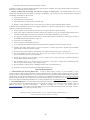
5
&RQVXPHU:KHHOHG:DUUDQW\&KDUW
([KLELW$
&RQVXPHU SHUVRQDO
KRXVHKROGXVHRQO\
3URGXFW&RPSRQHQW
5LGLQJ/DZQ7UDFWRUV
)UDPH&KDVVLV)URQW$[OH
(QJLQH
7UDQVPLVVLRQLIPDGHE\
+XVTYDUQD3HHUOHVV
7UDQVPLVVLRQLIWKLUGSDUW\
%DWWHU\
2WKHU1RQ([SHQGDEOH&RPSRQHQWV
5HVLGHQWLDO=HUR7XUQ0RZHUV 5=2QO\ (QJLQH
7UDQVPLVVLRQ
%DWWHU\
2WKHU1RQ([SHQGDEOH&RPSRQHQWV
5HVLGHQWLDO=HUR7XUQ0RZHUV 0=(= (QJLQH
7UDQVPLVVLRQ
%DWWHU\
2WKHU1RQ([SHQGDEOH&RPSRQHQWV
/((GJHU
(QJLQH
2WKHU1RQ([SHQGDEOH&RPSRQHQWV
:DON%HKLQG0RZHUV
(QJLQH
%DWWHU\
2WKHU1RQ([SHQGDEOH&RPSRQHQWV
6QRZ7KURZHUV
(QJLQH
2WKHU1RQ([SHQGDEOH&RPSRQHQWV
7LOOHUV
(QJLQH
%DWWHU\
2WKHU1RQ([SHQGDEOH&RPSRQHQWV
7LOOHU7LQHV
+RYHULQJ7ULPPHUV
(QJLQH
2WKHU1RQ([SHQGDEOH&RPSRQHQWV
&RPPHUFLDO DQ\FRPPHUFLDO 5HQWDO DQ\UHQWDO
SURIHVVLRQDOLQVWLWXWLRQDO
XVDJH
DULJFXOXWUDORULQFRPHSURGXFLQJ
XVHRWKHUWKDQ5HQWDO8VH
<HDUV
12:$55$17<
12:$55$17<
<HDUV
<HDU3URUDWHG
<HDUV
12:$55$17<
12:$55$17<
12:$55$17<
12:$55$17<
12:$55$17<
12:$55$17<
<HDU3URUDWHG
<HDUV
12:$55$17<
12:$55$17<
12:$55$17<
12:$55$17<
12:$55$17<
12:$55$17<
<HDU3URUDWHG
<HDUV
<HDU3URUDWHG
<HDU
12:$55$17<
12:$55$17<
<HDUV
GD\V
GD\V
<HDU3URUDWHG
<HDUV
12:$55$17<
12:$55$17<
12:$55$17<
12:$55$17<
<HDUV
GD\V
GD\V
<HDU3URUDWHG
<HDUV
12:$55$17<
12:$55$17<
12:$55$17<
12:$55$17<
12:$55$17<
12:$55$17<
<HDUV
<HDU
&RQVXPHU
&RPPHUFLDO
6HH6HSDUDWH(QJLQH0DQXIDFWXUHU
VRU0DQXIDFWXUHU
VZDUUDQW\
/&7(QJLQHVRQVSHFLILF6QRZ7KURZHUV7LOOHUVZDUUDQW\WKURXJK+XVTYDUQD
6HHUHIHUHQFHERIWKHZDUUDQW\VWDWHPHQW
5=7ZR<HDU&RQVXPHUZDUUDQW\SDUWVODERUZLWK+\GUR*HDU'LVWULEXWRUQHWZRUN
(=2QH<HDU&RPPHUFLDOZDUUDQW\SDUWVODERUZLWK+XVTYDUQD
7ZR<HDU&RQVXPHUZDUUDQW\SDUWVODERUZLWK+\GUR*HDU'LVWULEXWRUQHWZRUN
0=7ZR<HDU&RPPHUFLDOZDUUDQW\SDUWVODERUZLWK+\GUR*HDU'LVWULEXWRUQHWZRUN
GD\V
5HQWDO
/LPLWHG/LIHWLPH:DUUDQW\RQ7LOOHUWLQHVLVIRUWKHOLIHRIWKHSURGXFWRUVHYHQ\HDUVDIWHUWKHODVWGDWHRIWKHFRPSOHWH
XQLW
VILQDOSURGXFWLRQZKLFKHYHUFRPHVILUVW
38
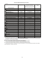
&RQVXPHU:KHHOHG:DUUDQW\&KDUW
([KLELW$
&RQVXPHU SHUVRQDO
KRXVHKROGXVHRQO\
&RPPHUFLDO DQ\FRPPHUFLDO 5HQWDO DQ\UHQWDO
SURIHVVLRQDOLQVWLWXWLRQDO
XVDJH
DULJFXOXWUDORULQFRPHSURGXFLQJ
XVHRWKHUWKDQ5HQWDO8VH
3URGXFW&RPSRQHQW
)URQW0RXQWHG'HFN5LGHUV
(QJLQH
7UDQVPLVVLRQ
<HDUV
12:$55$17<
%DWWHU\
<HDU3URUDWHG
12:$55$17<
2WKHU1RQ([SHQGDEOH&RPSRQHQWV
<HDUV
12:$55$17<
&XOWLYDWRUV
%DWWHU\
<HDU3URUDWHG
12:$55$17<
2WKHU1RQ([SHQGDEOH&RPSRQHQWV
<HDUV
12:$55$17<
3UHVVXUH:DVKHUV
0RGHO3:
(QJLQH
3XPS
<HDUV
12:$55$17<
2WKHU1RQ([SHQGDEOH&RPSRQHQWV
<HDUV
12:$55$17<
$OORWKHU3UHVVXUH:DVKHUV3:3:3:
(QJLQH
3XPS
<HDUV
<HDUV
2WKHU1RQ([SHQGDEOH&RPSRQHQWV
<HDUV
<HDUV
*HQHUDWRUV
(QJLQH
<HDUVQG<HDU
<HDUV*1QG<HDU
3DUWV2QO\
3DUWV2QO\
2WKHU1RQ([SHQGDEOH&RPSRQHQWV
6SUHDGHUV
6SUHDGHU
<HDU
<HDU
5RERWLF0RZHUV
5RERWLF0RZHU
<HDUV
GD\V
%DWWHU\
<HDU
<HDU
3DUWV$FFHVVRULHVLISXUFKDVHG
3 W $
L LI
K
G
$FFHVVRULHVHJJUDVVFDWFKHUEXPSHU
JXDUGDFFHVVRULHVHWF
<HDU
12:$55$17<
3DUWVHJEHOWVEODGHVHWF
GD\V
12:$55$17<
3DUWV$FFHVVRULHVLIUHSODFHGLQ:DUUDQW\6HUYLFH
5HSODFHPHQWSDUWVDQGRUDFFHVVRULHV
SURYLGHGXQGHUWKLV/LPLWHG:DUUDQW\DUH
ZDUUDQWHGRQO\IRUWKH%$/$1&(RIWKH
ZDUUDQW\SHULRGDSSOLFDEOHWRWKHSDUWRU
DFFHVVRU\WKDWZDVUHSODFHG
6HHWROHIW
6HHWROHIW
&RQVXPHU
&RPPHUFLDO
6HH6HSDUDWH(QJLQH0DQXIDFWXUHU
VRU0DQXIDFWXUHU
VZDUUDQW\
/&7(QJLQHVRQVSHFLILF6QRZ7KURZHUV7LOOHUVZDUUDQW\WKURXJK+XVTYDUQD
6HHUHIHUHQFHERIWKHZDUUDQW\VWDWHPHQW
5=7ZR<HDU&RQVXPHUZDUUDQW\SDUWVODERUZLWK+\GUR*HDU'LVWULEXWRUQHWZRUN
(=2QH<HDU&RPPHUFLDOZDUUDQW\SDUWVODERUZLWK+XVTYDUQD
7ZR<HDU&RQVXPHUZDUUDQW\SDUWVODERUZLWK+\GUR*HDU'LVWULEXWRUQHWZRUN
0=7ZR<HDU&RPPHUFLDOZDUUDQW\SDUWVODERUZLWK+\GUR*HDU'LVWULEXWRUQHWZRUN
12:$55$17<
12:$55$17<
12:$55$17<
12:$55$17<
12:$55$17<
12:$55$17<
12:$55$17<
12:$55$17<
12:$55$17<
12:$55$17<
<HDU
GD\V
<HDU
12:$55$17<
12:$55$17<
6HHWROHIW
5HQWDO
/LPLWHG/LIHWLPH:DUUDQW\RQ7LOOHUWLQHVLVIRUWKHOLIHRIWKHSURGXFWRUVHYHQ\HDUVDIWHUWKHODVWGDWHRIWKHFRPSOHWH
XQLW
VILQDOSURGXFWLRQZKLFKHYHUFRPHVILUVW
39
06/14/2011 TH